JETT-AutoclaveURS
- 格式:doc
- 大小:340.00 KB
- 文档页数:28

Raquel Bascones RecioSenior Implementation Consultant, Autodesk | @raquel_basconesNon-Geeks Guide to Optimizing Daily Workflows with Generative DesignPaolo Emilio SerraPrincipal Implementation Consultant, Autodesk | @PaoloESerraIntroductionRaquel Bascones RecioSr. Implementation Consultant2010 –2017: Architect & Landscape Architect 2017 –2019: Autodesk Global Product Support 2020: Autodesk Consulting**********************************TwitterLinkedInPaolo Emilio SerraPr. Implementation Consultant 2008 –2014 BIM Manager2013 –Revit API & Dynamo2014 –Autodesk Consulting************************@PaoloESerraLearning Objectives•Discover potential workflows for optimization •Learn how to compose Dynamo graphs ready for Generative Design in Revit•Learn how to implement Generative Design to optimize repetitive tasks•Learn how to adapt given examples to custom needsWhy Non-Geek?NO PYTHON SCRIPTINGNO THIRD-PARTY PACKAGES REQUIRED LIMITED DESIGNSCRIPT USE EASY TO FOLLOW TEMPLATEKey ConceptsAlgorithm[æl.ɡə.rɪ.ðəm]a set of mathematical instructions or rules that,especially if given to a computer,will help to calculate an answer to a problemSource: Cambridge DictionaryAlgorithm LinkGenerative Design[ˈdʒen.ər.ə.tɪv dɪˈzaɪn]a process that uses iteration to refine the potential solutions to a problem against certainmetrics and constraints.Source: WikipediaGenerative Design LinkMachine Learning[məˈʃiːn ˈlɜː.nɪŋ]computer algorithms that improve automatically through experience.Source: WikipediaMachine Learning LinkGenerative Design WorkflowGenerative Design Workflow LinkTry, Learn, Repeat•Goal Sank as many ships as possible•Design Space Grid of cells with two coordinates•Strategyo Pick a cell (Generate)o Wait for result (Evaluate)o Decide next move (Evolve)•Winning Criteriono Maximize sank shipso Maximize hitso Minimize attemptsCC BY-SA 4.0Surrogate Model•Abstract representation of a real problemo It is the result of the initial analysiso It helps focusing on the key featureso It supports the visualization of partsImage Source –Einstein in Oxford 1933Generative Design in RevitCreate logic in Dynamo & export to GD Launch GD inRevit andcreate studyExploreoutcomesS elect “Best inClass”Adopt solutionin RevitINPUTS & VARIABLES•Number/Integer slider, Boolean or Revit Selection nodes•Check “Is Input” for each input node•Rename nodes to a unique nameOUTPUTS & METRICS•Only Watch nodes with a Number value•Check “Is Output” for each output node •Rename nodes to a unique nameINTERACTION WITH REVIT•Generation can only be executed with Dynamo code •All references to Revit data should be stored in a Data.Remember node•Data.Gate node will create or modify elements in Revit when you select “Create Revit Elements”DISPLAY•The geometry for the different options in the study will be displayed as in the Dynamo Graph when it was exported•It is highly recommended to colour the geometry with codes for visual comparisonApplications01 Pick ApartmentStatementFind the option from a list that has the most favourable combination of price, area, number of rooms,management costs, energy costs, most recent construction, on an intermediate level, with a lift andpossibly with furnitureTo finalize the selection there is need to examine the pictures, visit the apartment and evaluate thesurroundings, etc.Statement•Inputs / Constraintso The catalog with all characteristics of the apartments •Variableso The index of the apartment•Objectiveso Price/Costs [-]o Area [+]o Rooms [+]o Year of Construction [+]o Intermediate level 2-6 [+]o Lift Y/N [+]o Furniture Y/N [+]01 Pick Apartment | Process Diagram Link01 Pick Apartment | Study in action Link01 Pick Apartment | Similar applications•Selection of equipment types/models•Selection of Cross-Sections•Selection of Materials02 Can I park here?StatementOptimize the position of the car inside a parking bay so the driver´s door can open, the vehicle is inside the designated area, and there are no clashesStatement•Inputs / Constraintso Car sizeo Parking bay shape & dimensionso Obstacles (i.e. walls, columns, etc.) o Neighbouring parking bayso Distances allowances •Variableso Driver’s door opening angleo Density of the grid of origin pointso Origin pointo Rotation angle•Objectiveso Intersection with neighbours [-]o Clashes with obstacles [-]o Area inside parking bay [+]02 Can I park here?| Process Diagram Link02 Can I park here?| Study in action Link02 Can I park here? | Similar applications•Logistics planning•Building outline in plot•Tree planting in urban environments03 Shape arrangementProblem StatementFind an arrangement of any number of shapes with any number of sides so that there are no overlaps, and the result is esthetically pleasing whilst compactProblem Statement•Inputs / Constraintso The geometrical shapes•Variableso The order/sequence in which the shapes areprocessedo The side used to connect the next shapeo The parameter along the side used as anchor point for the following shape•Objectiveso Bounding Box Area [-]o Overlapping Area [-]o Perimeter [-]o Perimeter over Area [-]03 Shape arrangement | Process Diagram Link03 Shape arrangement | Study in action Link03 Shape arrangement | Similar applications•Tile / façade patterns•Floor planning•Site layout04 Floor Tiles PatternStatementReducing waste on site is one of the priorities to achieve a greener construction industry. By optimizing the pattern and location, less time and material will berequired.Statement•Inputs / Constraintso Tile size (Width/Length)o Joint sizeo Overlapo Minimum cut sizeo Floor geometry •Variableso Angleo Origin of the first tile •Objectiveso Number of tiles [-]o% Completed tiles [+]o% Non-compliant cuts [-]04 Floor Tiles Pattern | Process Diagram Link04 Floor Tiles Pattern | Study in action Link04 Floor Tiles Pattern | Similar applications•Wall & façade panels•Archives & warehouse layout•Open office/ classroom design05 Bathroom LayoutStatementBathroom elements have clear needs of space and use area, as well as relationship with other plumbing elements and walls. However, there is no single option so computer and designer should work hand by hand in finding the best solution for each situation.Statement•Inputs / Constraintso Type of fixtureso Size of fixtureso Space geometry and conditions (i.e. doors, windows…)•Variableso Permutation (order of the fixtures)o Origin pointo Distance between fixtures•Objectiveso% Fixtures geometry outside boundary [-]o Element clashes [-]o% Free use area [+]o% Use area outside boundary [-]o Distance to waste pipe [-]o Perimeter curves < 200mm long [-]05 Bathroom Layout | Process Diagram Link05 Bathroom Layout | Study in action Link。
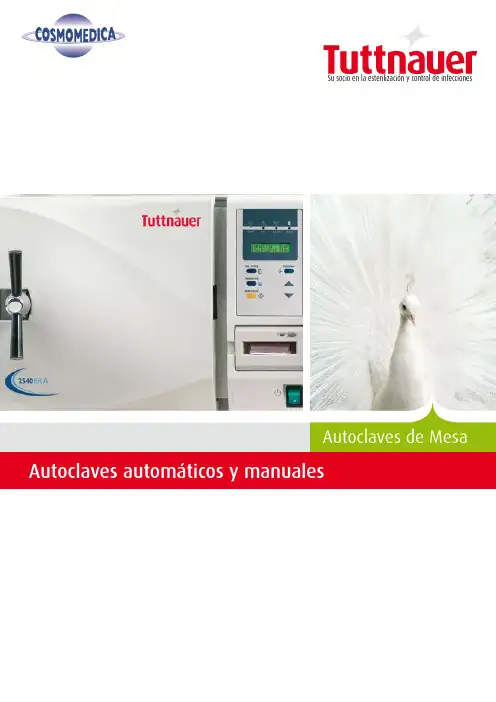
Autoclaves automáticos y manualesAutoclaves de MesaSu socio en la esterilización y control de infeccionesBrindamos constantemente soluciones a distintos mercados y para diversas aplicaciones, ofreciendo una amplia gama de productos innovadores para limpieza, desinfección y esterilización, que varían según el espacio y las aplicaciones requeridas, que incluyen:• Una extensa variedad de autoclaves de mesa para clínicas y consultorios dentales, clínicas pequeñas y medianas o sirviendo como unidad secundaria en centros médicos y hospitales• Productos de limpieza, desinfección y esterilización para uso del Departamento Central de Suministros de Esterilización (CSSD, por sus siglas en inglés)• Esterilizadores industriales para hospitales e institutos de investigación• Autoclaves para laboratorio, de diversos tamaños y aplicaciones• Lavadoras desinfectadoras para clínicas dentales, hospitales y laboratorios Nuestros autoclaves integran un diseño probado y características de ingeniería, dando como resultado una solución duradera y garantizada que cumple con varias normas internacionales como FDA (Dirección de Alimentos y Medicinas de Estados Unidos), ASME (Sociedad Estadounidense de Ingenieros Mecánicos), ISO (Organización Internacional de Normas) y las directivas para dispositivos médicos de la Comunidad Europea, entre otras.Alianzas globalesEn Tuttnauer estamos convencidos que los negocios implican personas que tratan con personas; por ello, nos enorgullecemos de nuestra reputación para forjar relaciones sólidas y duraderas a través de décadas con nuestros clientes, trascendiendo fronteras, basadas en el compromiso y la confianza.Nuestra flexibilidad es su ventajaAdemás de nuestra incomparable gama de productos, ofrecemos también soluciones completas, llave en mano, que incluyen la planeación, el diseño y la instalación del equipo, así como estudios de viabilidad y asesoría para proyectos de todo tipo. Respaldado por su experiencia en la industria y una trayectoria probada de éxito, Tuttnauer continúa ayudando a institutos médicos y de investigación en todo el mundo, a planear y aplicar sus políticas de esterilización y control de infecciones.Un campo de especialización, muchos campos de aplicaciónTuttnauerSu socio en la esterilización y control de infeccionesPerfil de la empresaDurante más de 80 años, los productos de Tuttnauer para la esterilización y el control de infecciones se han ganado la confianza de hospitales, universidades, institutos de investigación, clínicas y laboratorios alrededor del mundo. Tuttnauer, reconocido mundialmente como líder en la esterilización y control de infecciones, suministra una gama de productos de alta calidad en más de 100 países.Tuttnauer invierte toda su energía y recursos en un solo campo de especialización: esterilización y control de infecciones. Desde el principio, en 1925, trabajamos en proyectos conjuntos de gran escala con los principales institutos de investigación y universidades. Esta cooperación nos ha permitido mantenernos a la vanguardia de nuestro campo, desarrollando e integrando los métodos y tecnologías más avanzados..Compartimos su compromiso, ayudando a proteger a su personal y pacientes contra lapropagación de enfermedades infecciosas y mantener un ambiente libre de riesgos.Debido a la creciente demanda para establecer lineamientos de esterilización cadavez más estrictos, especialmente desde la aparición del SIDA y del desarrollo de lasmutaciones virales, la lucha por un entorno más limpio y seguro se ha vuelto un retomás difícil.¿Qué es la esterilización?La esterilización es un componente vital de los procedimientos de control de infecciones.El término se emplea para describir todo el conjunto de actividades realizadas con el finde lograr un entorno pulcro, libre de enfermedades. La esterilización se define como laeliminación de todo agente, bacteria o virus transmisible de toda superficie, instrumentomédico, alimento o producto que debe ser utilizado de manera segura por el usuario, sinponerlo en peligro.Nuevas regulaciones y la necesidad de contar con una esterilización adecuada en clínicasprivadas, centros de tatuajes y salones de belleza han dado lugar a la creciente demandade esterilizadores fáciles de utilizar y mantener.Estamos convencidos que conocimientos adecuados,tecnología avanzada y un equipo fácil de utilizarcontribuyen a obtener mejores resultados de esterilización.Serie de autoclaves automáticos de TuttnauerHoy en día, las clínicas médicas y dentales exigen una mejor esterilización. Puede contar con Tuttnauer como su socio para proteger y ganarse la confianza de sus pacientes. Nuestra tecnología de punta para la esterilización fue diseñada para brindarle calidad.Los autoclaves automáticos de Tuttnauer le darán el máximo rendimiento por su inversión, ya que le ofrecen:• Ciclos rapidos • Poco mantenimiento • Durabilidad • SeguridadBeneficios:• Ciclos rápidos que optimizan la disponibilidad del instrumental esterilizado, listo para ser usado• Sistema de control fácil de usar, con teclas de una sola acción, aumentando así la productividad• Monitoreo mejorado para registrar constantemente los resultados de la esterilización• Autoclaves duraderos, fáciles de mantener, que prácticamente garantizan la ausencia de tiempos muertos Características de la serie automática:• programas preprogramados de esterilización• Posibilidad de programar y personalizar los parámetros del ciclo para satisfacer sus propias necesidades• Sistema de control de alta precisión para obtener resultados de esterilización exactos• Impresora integrada (opcional) para documentar la información del ciclo• Puerto de conexión a PC para almacenar los resultados del ciclo• Monitoréo de la presión y temperatura• Pantalla muy fácil de usar y entender• Recuperación de la información del ciclo en caso de falla eléctrica o interrupción del mismo• Detector de nivel de agua con sistema de apagado automático en caso de bajo nivelCapacidad :Nuestros modelos de gran capacidad están disponibles en tamaños de cámara de 65 y 85 litros. Estos modelos fueron diseñados para las clínicas con alto volumen de rotación de instrumental,disminuyendo de esta manera costos operativos. Crear un ambiente seguro es nuestra prioridad.5Doble protección contra apertura de puertaVentajas de seguridad y comodidad:• Integración sencilla y directa al entorno de trabajo, gracias a su diseño compacto y aislamiento térmico• Cámara y puerta de acero inoxidable tipo 16L con acabado de electro-pulido.• Switch automático de bloqueo para evitar el comienzo de un ciclo si la puerta no está debidamente cerrada• Dispositivo de protección en puerta para evitar la apertura a altas presiones• Sistema de seguridad de apagado automático para evitar el sobrecalentamientoAcero inoxidable tipo 16L con acabado de electro-pulido00626¿Cómo seleccionar el modelo que se adapt e a sus necesidades?La serie de autoclaves automáticos de Tuttnauer ofrece una amplia gama de modelos: E, EK, EA y EKA E / EKEstos dos modelos cuentan con dos modos distintos de operación: el modo rápido, en el modelo EK, disminuye la etapa de calentamiento en más de un 50%, por lo que los ciclos de esterilización son más rápidos y eficaces, permitiendo así una mayor cantidad de ciclos. El EK es la elección perfecta para las clínicas activas. El modelo estándar E ofrece todas las características de confiabilidad de los autoclaves automáticos.7Bomba de aire para secado a puerta cerrada:Con los autoclaves EA y EKA y sus ciclos de secado ultrarrápidos y eficaces, su productividad aumentará de manera considerable. Ambos modelos presentan además la ventaja de una bomba de aire sumamente eficaz que permite secar a puerta cerrada. Los autoclaves EA y EKA fueron construidos para brindar una mejor esterilización con la posibilidad de secar paquetes e instrumental empacado.Beneficios:• Una esterilización y secado más profundos• Un secado más rápido para reducir la duración total del ciclo • Un filtro de aire HEPA de 0. µm que permite un secado estéril, libre de bacteriasModelos con cámara de 34 litrosModelos con cámara de 64 / 85 litrosModelos con cámara de 7.5 litrosModelos con cámara de 19 / 23 litrosProbados con instrumentos desenpacados. El tiempo de ciclo incluye calentamiento, esterilización y descompresión. El tiempo de ciclo puede variar de acuerdo con la carga y tensión eléctrica.- All printers are optionalEA / EKA8Serie de autoclaves manuales TuttnauerSimplicidad de operación M/MKEl autoclave manual es un esterilizador accesible para las clínicas privadas que no desean comprometer la calidad, seguridad y confiabilidad.Los autoclaves manuales de Tuttnauer representan una solución sin esfuerzo. El equipo será conectado y estará listo para der usado. Una vez instalado, el esterilizador no requiere prácticamente mantenimiento, reduciendo así los costos de operación.Beneficios:• Tiempo de vida muy largo.• Componentes duraderos que reducen significativamente los gastos de mantenimiento• Fáciles de usar, por lo que no se requiere personal especialmente capacitado para operarlosVentajas de seguridad y comodidad:• Aislamiento térmico y operación silenciosa que crean un ambiente de trabajo agradable• Cámara y puerta muy resistentes de acero inoxidable tipo 16L con acabado de electro-pulido• Cerradura en puerta que evita que ésta se abra mientras la cámara está presurizada.• Dispositivo de protección en puerta para evitar que se abra a alta presión• Sistema de seguridad de apagado automático para evitar el sobrecalentamiento• Detector de nivel de agua insuficiente con sistema de apagado automático11Indicador de presión 2Cronómetro 3Temperatura 4Selector de funcionesModelos con cámara de 64 / 85 litrosModelos con cámara de 34 litrosModelos con cámara de 7.5 litros Modelos con cámara de 19 / 23 litros0062Probados con instrumentos desenpacados. El tiempo de ciclo incluye calentamiento, esterilización y descompresión. El tiempo de ciclo puede variar de acuerdo con la carga y tensión eléctrica.910Tuttnauer se reserva el derecho de cambiar partes y/o accesorios, según sus necesidades,sin previo aviso.Modelo2540MKADimensiones de cámara (ancho x largo, en mm)5 x 76Volumen de cámaraLitros Duración de ciclo con cámara fría 16 minutos Duración de ciclo con cámara caliente1 minutos2540 MKA – El primer autoclave manual con secado a puerta cerradaNuestra más reciente creación, el autoclave 5 0 MKA cuenta con un sistema de apagado automático de la resistencia térmica, al final del ciclo de esterilización, a fin de ahorrar energía y aumentar su seguridad y productividad. Antes de dejar la clínica, configure el autoclave 5 0 MKA a modo nocturno, inicie un ciclo y los instrumentos estarán esterilizados y listos para usarse cuando regrese.• Bomba de aire para activar el secado a puerta cerrada • Ciclo de esterilización de una sola acción• Protección de seguridad por sobrecalentamiento• Apagado automático en modo nocturno, a fin de ahorrar tiempo y energía1Indicador de las distintas etapas del ciclo 2Indicador de presión3Interruptor de encendido y apagado 4Timer para la esterilización 5Switch de la bomba de agua 6Timer para secado y esterilización 7Switch para modo nocturno 8Selector de temperatura16587 AccesoriosMáquinas selladoras por impulsoLa esterilización es efectiva sólo si se mantiene la esterilidad de los instrumentos desde la esterilización hasta su uso. El proceso de cierre asegura que el instrumental permanezca sellado después de su esterilización y se mantenga en perfectas condiciones de esterilidad mientras no se use. Nuestra gama de selladoras por impulso, confiables y rápidas, cumple con las más estrictas normas de calidad y seguridad (DIN 5895 -7). Para permitir una rotación rápida del instrumental, ofrecemos varios tipos de máquinas selladoras automáticas.Destilador de aguaUtilice agua desmineralizada para proteger su autoclave e instrumentos.Chamber Brite™El Chamber Brite™ limpia y elimina de manera efectiva los residuos calcareos de la camara, del reservorio y de la tuberia de cobre en cualquier tipo de autoclave.El tiempo de ciclo puede variar de acuerdo con la carga y tensión eléctrica.• Aumenta la vida del sistema de tuberías del autoclave• Agua destilada a una fracción del costo del agua destiladaembotellada.11Tuttnauer presenta su gama de soluciones para esterilización, desinfección y limpieza:Esterilizadores de gran tamaño para distintas necesidades delmercado e industria Autoclaves para laboratorio de distintos tamaños yaplicacionesLavadoras / desinfectadoraspara hospitales y laboratoriosMás opciones de Tuttnauer:Esterilizadores de mesa con pre y post-vacío diseñados pararealizar ciclos clase BSu socio en la esterilización y control de infecciones。

2JetterManufacturer Eaton Automation AG Spinnereistrasse 8-14 CH-9008 St. Gallen Switzerland Support Region North America Eaton Corporation Electrical Sector 1111 Superior Ave. Cleveland, OH 44114 United States 877-ETN-CARE (877-386-2273) Other regions Please contact your supplier or send an E-Mail to: a ******************* Original instructions The German version of this document is the original instructions Editor Manfred Hüppi Brand and product names All brand and product names are trademarks or registered trademarks of the owner concerned. Copyright © Eaton Automation AG, CH-9008 St. Gallen All rights reserved, also for the translation. None of this document may be reproduced or processed, duplicated or distributed by electronic sytems in any form (print, photocopy, microfilm or any other process) without the written permission of Eaton Automation AG, St. Gallen. Subject to modifications.Imprint1General (5)1.1Aim and purpose of this document (5)1.2Comments about this user manual (5)1.3Additional documentation (5)2Communication overview (7)2.1Operating principle (7)2.2Supported systems (9)2.2.1Client (9)2.2.2Server (9)2.3Communication parameters (10)2.4Supported data (11)2.4.1Addresses (11)2.4.2Alignement (11)2.4.3Data type (11)3Hardware (13)4Software (15)4.1GALILEO (15)4.1.1Configuring communication in GALILEO (15)4.1.2Addressing variables in GALILEO (16)4.2THC (17)4.2.1Configuration (17)1General1.1Aim and purpose of this documentThis user manual provides the information required for connecting Eaton Automation automationcomponents to Jetter controllers.This user manual describes the installation and configuration. The operating system and applicationsoftware are not described.1.2Comments about this user manualPlease send any comments, recommendations or suggestions relating to this user manual to********************.1.3Additional documentationFurther documents may be helpful in addition to this user manual.The following documentation can be obtained from our website ():[1]MN05010007ZSystem Description Windows CE2Communication overview2.1Operating principleThe communication uses the PCOM5- or PCOM3-Protocol via the RS232 interface. Communicationis implemented from a panel or a PC with exactly one «Controller» via the interfaces LCD or PC.Fig. 1Operating principle DELTA / NANOFig. 2Operating principle MIKRO / PASE-E2.2Supported systems2.2.1ClientThe following devices control the communication to Jetter controllers:⏹PC with GALILEO Open and RS232 interface⏹MICRO PANEL XV Series with RS232 interface⏹MICRO PANEL M Series with RS232 interfaceThe term «Client» in the following documentation stands for these devices and the software runningon them.2.2.2ServerThe following controllers are supported:⏹DELTA⏹NANO⏹MIKRO⏹PASE-EThe term «Controller» in the following documentation stands for these devices.2.3Communication parametersThe baud rate settings for «Client» and «Controller» must be identical.The baud rate for the Jetter MIKRO is 9600 Baud.2.4Supported data2.4.1AddressesController Address range Descriptionall R0 … R65534RegisterNANO R65024 … R65279Floating-point registerDELTA R62208 … R62463Floating-point registerPASE-E R8960 … R9215Floating-point registerNANO M0 … M65534FlagDELTA M0 … M65534FlagPASE-E M0 … M65534FlagMIKRO M0 … M4095FlagTab. 1Supported addresses2.4.2AlignementFlags on certain addresses can be addressed as an array with maximally 32 bits. Flags on all otheraddresses can be addressed as single bit only.Controller Address range for communication as arrayDELTA M256 … M2047NANO M256 … M2047PASE-E M256 … M2047MIKRO M256 … M2655Tab. 2Address range flag arrays2.4.3Data typeData type Descriptionregister Register 24 bitfloat Floating-point register 32 bitflag Flagtext Register interpreted as textTab. 3Supported data types☞ The following data types are currently not supported:⏹input⏹output⏹task3HardwareBoth «Client» and also «Controller» are provided with an RS232 interface which can be used toconnect them. Information on installation, wiring and commissioning is provided in the operatinginstructions of the devices.4Software4.1GALILEOThe GALILEO visualization software supports several parallel communication channels. A«Controller» is assigned one serial interface exclusively. It is not possible to configure severalcommunication channels to the same «Controller».4.1.1Configuring communication in GALILEOChoose «Jetter – DELTA», «Jetter – MIKRO», «Jetter – NANO» or «Jetter – PASE-E» and set thecommunication parameters.1)Configuring communication in GALILEOCommunication parameter CommentBaud rate The baud rate settings for «Client» and «Controller» must beidentical.Status Refresh Read the Online Help of your GALILEO version.Tab. 4Communication parameter DELTA, NANO and PASE-ECommunication parameter CommentStatus Refresh Read the Online Help of your GALILEO version.Tab. 5Communication parameter MIKRO4.1.2Addressing variables in GALILEOThe Chapter 2.4 describes which variables of the «Controller» you can access. GALILEO supportsthe following address forms and data types:GALILEO ControllerVariables on the controller.R%d.%dR%dM%dTab. 6Address forms in GALILEOGALILEO ControllerBit / Error bit R, MByte RWord 1) 4)RDWord 2) 4)RFloat R (not on MIKRO)String, 1 byte per character, zero terminated RString, 1 byte per character, Pascal R (according to Jetter convention3))String, 1 byte per character, not terminated RString, 1 word per character, zero terminated RString, 1 word per character, Pascal RString, 1 word per character, not terminated RStructure 2) 5) 6)RSystem 1)RTab. 7Data types in GALILEO1) A 24 bit register is mapped to 16 bits.2) A 24 bit register is mapped to 32 bits3)String with 1 byte per character, using the Pascal convention. Therefore prefer to use this datatype in GALILEO.4)As of GALILEO 7.2.9: Sign extension corresponding to data type.5)Sign extension6)GALILEO does not show the correct addresses.4.2THCA THC component (THC = Tag Handle Container) is used on the «Client» for the communication tothe server. As a GALILEO user, you do not have anything to do directly with the THC component.However, you need the following information when using, for example, the ThcSymbolicClient libraryin XSoft-CoDeSys or MXpro.4.2.1ConfigurationConfiguration parameter ValueComponent MicroPanel.Jetter.dllProgId MicroInnovation. DELTA.TagServerMicroInnovation. NANO.TagServerMicroInnovation. PASE-E.TagServerMicroInnovation. MIKRO.TagServerTab. 8THC Configuration parameterCommunication parameter Data type CommentLocalSerialPort String Serial interface used by the cliente.g. COM1BaudRate Unsigned32 Baud rate of the serial interfacee.g. 9600Tab. 9THC Communication parameters DELTA, NANO und PASE-ECommunication parameter Data type CommentLocalSerialPort String Serial interface used by the cliente.g. COM1Tab. 10THC Communication parameter MIKRO。
jetlinks 插件开发原理JetLinks is an open-source IoT (Internet of Things) platform with a plugin architecture that allows developers to extend its functionality. 插件使用 Java 语言开发,以 JetLinks 插件为基硖可以快速的开发 IoT 设备的管理,数据采集和远程控制等功能。
The plugin development principle is based on the Spring Framework, which provides a flexible and scalable way to add new features to the platform. 这个插件开发原理是基于 Spring Framework,它提供了一种灵活而可扩展的方式来为平台添加新功能。
By utilizing the Spring Framework, developers can create plugins using Java and easily integrate them into the JetLinks platform. 利用 Spring Framework,开发者可以使用 Java 来创建插件,并轻松地集成到 JetLinks 平台中。
The plugin development process involves creating a new Java project and adding the necessary dependencies to build the plugin. 插件开发的流程涉及创建一个新的Java项目,并添加必要的依赖来构建插件。
Developers can then define the functionality of the plugin by implementing the required interfaces and extending the base classes provided by the JetLinks platform. 开发者可以通过实现所需的接口和扩展 JetLinks 平台提供的基础类来定义插件的功能。


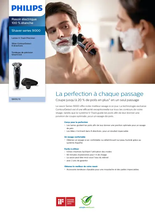
Shaver series 9000 Lames V-Track PrecisionTêtes ContourDetect8 directionsTondeuse de précision SmartClickS9051/13La perfection à chaque passage Coupe jusqu'à 20 % de poils en plus* en un seul passageLe rasoir Series 9000 offre notre meilleur rasage à ce jour. La technologie exclusive ContourDetect est d'une efficacité exceptionnelle sur tous les contours de votre visage, tandis que le système V-Track guide les poils afin de leur donner une position de coupe optimale, pour un rasage de près.Conçu pour la perfectionLes lames guident les poils afin de leur donner une position optimale pour un rasagede prèsLes têtes s'inclinent dans 8 directions, pour un résultat impeccableUn rasage confortableObtenez un rasage à sec confortable ou rafraîchissant sur peau humide grâce ausystème AquaTecFacile à utiliserIcônes intuitives facilitant l'utilisation des modes60 minutes d’autonomie pour 1 h de chargeLe rasoir peut être rincé sous l'eau du robinetavec 2 ans de garantieObtenez le meilleur de votre rasoirAccessoire tondeuse clipsable pour une moustache et des pattes impeccablesPoints fortsLames V-Track PrecisionObtenez un rasage parfait. Les lames V-Track Precision positionnent les poilsidéalement pour une coupe optimale, quelle que soit leur longueur, et même s'ils sont couchés. Elles coupent 30 % plus près enmoins de passages, pour une peau préservée.Têtes ContourDetect 8 directionsSuivez les contours de votre visage et de votre cou grâce aux têtes ContourDetect quis'inclinent dans 8 directions. Vous couperez 20 % de poils en plus à chaque passage, pour un rasage de près confortable.AquaTec Wet & DryRasez-vous comme bon vous semble. Avec le système AquaTec Wet & Dry, vous pouvez opter pour un rasage à sec rapide etconfortable, ou vous raser sur peau humide -avec du gel ou de la mousse - même sous la douche.Tondeuse de précision SmartClickClipsez notre tondeuse de précisionrespectueuse de la peau pour parfaire votre style. C'est la solution idéale pour entretenir la moustache et tailler les pattes.Écran LED à 3 niveauxL'écran intuitif affiche des informations pratiques pour obtenir des performances optimales de votre rasoir : - Indicateurs decharge 3 niveaux et de verrouillage - Indicateur de nettoyage - Indicateur de batterie faible -Indicateur de remplacement des têtes60 minutes d’autonomieDésormais, grâce à la meilleure autonomie des rasoirs Philips, le système de charge offre deux options pratiques : 1 h de charge pour60 minutes d'autonomie, ou une charge rapide pour un rasage. Tous les modèles de rasoirs Series 9000 sont conçus pourfonctionner uniquement en mode sans fil, pour une sécurité totale en milieu humide.Rasoir entièrement lavableIl vous suffit d'ouvrir la tête de rasage et de larincer soigneusement sous l'eau.iF DESIGN AWARD 2015Rasoir Series 9000Précision, maîtrise et maniabilité sont les caractéristiques clés du rasoir Series 9000. Le système V-Track guide les poils afin de leur donner une position de coupe optimale, pour un rasage de près, tandis que les têtes flottantes 8 directions coupent plus de poils à la fois, pour un résultat net en moins de passages. Le système AquaTecWet & Dry permet un rasage à sec agréable ou un rasage rafraîchissant à l'eau, avec un gel ou une mousse à raser, pour encore plus deconfort.Logo « Produit Vert » PhilipsLes produits verts de Philips permettent de réduire les coûts, la consommationénergétique et les émissions de ment ? Grâce à une améliorationenvironnementale significative dans un ou plusieurs de nos champs d'actionsécologiques clés (efficacité énergétique,conditionnement, substances dangereuses,poids, recyclage, recyclabilité et durabilité).CaractéristiquesPerformance de rasageSuivi des contours: Têtes ContourDetect8 directionsSkinComfort: AquaTec Wet & DrySystème de rasage: Lames V-Track Precision, Système Super Lift&CutAccessoiresSmartClick: Tondeuse de précision Trousse: Trousse de voyage Facile d'utilisationAfficheur: Indicateur d'autonomie à 3 niveaux,Voyant de charge faible, Voyant de nettoyage,Voyant de remplacement des têtes, Indicateurde verrouillage pour les transportsNettoyage: Entièrement lavableDesignCouleur: CeresManche: Design ergonomique pour une bonneprise en mainAlimentationType de batterie: Lithium-ionAutonomie: 60 min / 20 rasagesCharge: Charge complète en 1 heure, Chargerapide pour un rasageTension automatique: 100-240 VConsommation en veille: 0,1 WConsommation maximale: 9 WEntretienDeux ans de garantieTête de rechange: Remplacer tous lesdeux ans avec SH90* Coupe jusqu'à 20 % de poils en plus par rapport auxmodèles SensoTouch© 2019 Koninklijke Philips N.V. Tous droits réservés.Les caractéristiques sont sujettes àmodification sans préavis. Les marques commerciales sont la propriété de Koninklijke Philips N.V. ou de leurs détenteurs respectifs.Date de publication 2019‑08‑01Version: 2.0.1EAN: 08 71010 37822 23 。
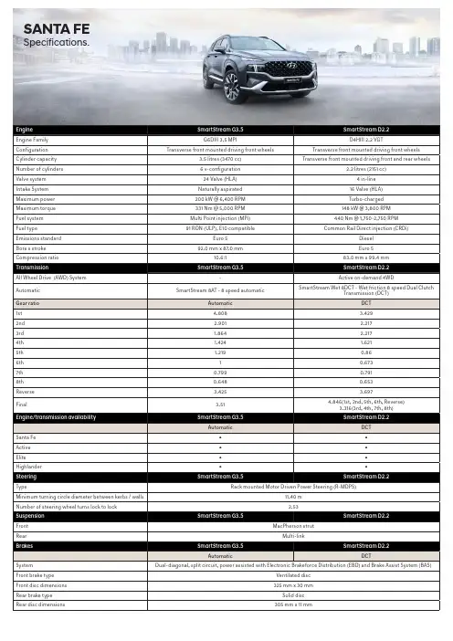
SANTA FE Specifications.Weight SmartStream G3.5SmartStream D2.2Automatic DCTKerb weight - lightest 1735 kg1820 kgKerb weight - heaviest1858 kg1943 kgGross Vehicle Mass (GVM)2560 kg2610 kgPermissible Axle Weight (PAW) - front1350 kg1350 kgPermissible Axle Weight (PAW) - rear1450 kg1450 kgRoof rack load limit100 kg100 kgTowing capacity SmartStream G3.5SmartStream D2.2Automatic DCTBraked2500 kg2500 kgUnbraked750 kg750 kgMaximum towball weight200 kg200 kgFuel consumption*SmartStream G3.5SmartStream D2.2Automatic DCTCombined (L/100km)10.5 6.1Urban (L/100km)14.77.5Extra Urban (L/100km)8.1 5.3 - combined (g/km)244160CO2Fuel tank volume67 L*Source: Australian Design Rule 81/02 static laboratory combined average city and highway cycle test. Real world fuel consumption will vary depending on a combination of driving habits, the condition of the vehicle,and other factors such as road, traffic and weather conditions. ADR 81/02 test results are meant for comparison purposes only.Dimensions Santa Fe Active Elite Highlander ExteriorLength4785 mmWidth1900 mmHeight (with roof rails)1685 mm (1710 mm)Wheelbase2765 mmWheel track - front / rear1651mm / 1661mm1646mm / 1656mm1637mm / 1647mm1637mm / 1647mm Minimum ground clearance (based on kerb weight) 176 mm176 mm176 mm176 mmApproach / departure / ramp break over angle SmartStream G3.5: 17.9° / 19.3° / 17.3°SmartStream D2.2: 17.9° / 19.3° / 16.8°InteriorHead room front / centre (w/ sunroof)1016 / 990 mm (974 / 958 mm)Leg room front / centre/ rear1052 - 1120 / 1040 / 746 mmShoulder room front / centre / rear1500 / 1480 / 1344 mm1500 / 1450 / 1344 mmHip room front / centre / rear1460 / 1430 / 1081 mmCargo area - VDA (minimum / maximum)571 / 782 LitresWheels & tyres Santa Fe Active Elite Highlander Wheel type Alloy Alloy Alloy AlloyWheel dimensions17 x 7.0J +4718 x 7.5J +49.520 x 8.5J +5420 x 8.5J +54Tyre dimensions235/65R17 108V235/60R18 107V255/45R20 105V XL255/45R20 105V XLSpare wheel type Full size alloy Full size alloy Full size alloy Full size alloyDriving convenience Santa Fe Active Elite HighlanderElectronic Parking Brake (EPB) (with auto hold function)●●●●Integrated Memory System (IMS) - driver’s seat---●One touch turn signal - 3, 5, or 7 flashes●●●●Rain sensing wipers-●●●Rear wiper - 2-stage, with auto wipe on reverse ●●●●Remote start - via Smart Key-●●●Shift By Wire (SBW) - electronic gear shift buttons-●●●Smart Key with push button start-●●●Steering wheel mounted controls - audio, phone, cruisecontrol, lane safety & trip computer●●●●Tilt & telescopic steering column●●●●Driving engagement Santa Fe Active Elite Highlander4WD Lock (available on AWD Diesel variants only)●---Drive Mode - 4 settings : Comfort, Eco, Sport, Smart●●●●Multi Terrain Mode - 3 settings : Snow, Mud, Sand(available on AWD Diesel variants only)-●●●Paddle shifters-●●●Active safety Santa Fe Active Elite Highlander Electronic Stability Control (ESC) including;Anti-lock Braking System (ABS)●●●●Brake Assist System (BAS)●●●●Electronic Brakeforce Distribution (EBD)●●●●Downhill Brake Control (DBC)●●●●Hill-start Assist Control (HAC)●●●●Multi-Collision Braking (MCB)●●●●Traction Control System (TCS)●●●●Vehicle Stability Management (VSM) ●●●●Hyundai SmartSense ™ including;Blind-Spot Collision-avoidance Assist - Rear (BCA-R)●●●●Blind-Spot View Monitor (BVM)---●Driver Attention Warning (DAW)●●●●Forward Collision-Avoidance Assist (FCA) - camera andradar type, including:- Car/Pedestrian/Cyclist detection●●●●- City/Urban/Interurban operational speeds- Junction Turning (FCA-JT) functionalityHigh Beam Assist (HBA)●●●●Lane Following Assist (LFA)●●●●Lane Keeping Assist - Line/Road-Edge (LKA-L/R)●●●●Parking Collision-avoidance Assist-Rear (PCA-R)---●Rear Cross-Traffic Collision-Avoidance Assist (RCCA)●●●●Rear Occupant Alert (ROA)●●--Rear Occupant Alert (ROA) - Advanced--●●Remote Smart Parking Assist System (RSPAS)---●Safe Exit Assist (SEA)-●●●Smart Cruise Control (SCC) with Stop & Go●●●●Surround View Monitor (SVM)---●Other featuresEmergency Stop Signal (ESS)●●●●Parking Distance Warning-Front (PDW-F) - 4 sensors,with guidance display-●●-Parking Distance Warning-Reverse (PDW-R) - 4 sen-sors, with guidance display●●●-Parking Distance Warning-Front (PDW-F) - 6 sensors,with guidance display---●Parking Distance Warning-Reverse (PDW-R) - 6 sen-sors, with guidance display---●Rear view camera with dynamic guide lines●●●●Speed limiter ●●●●Tyre Pressure Monitoring System (TPMS) - individualtyre pressure readout●●●●Passive safety Santa Fe Active Elite Highlander AirbagsFront airbags - driver & front passenger●●●●Front centre side●●●●Side (thorax) airbags - driver & front passenger●●●●Side curtain airbags - 1st & 2nd rows●●●●Roll-over Sensor●●●●DoorsImpact sensing auto door unlock●●●●Electronic child safety lock system -●●●SeatbeltsPretensioners, load limiters & height adjustable uppermounts on front seat belts●●●●Pretensioners & load limiters on rear (outboard) seatbelts - 2nd row●●●●Seat belt reminder - front & rear seatbelts●●●●Seat belt holder - 2nd & 3rd rows●●●●SeatingHeight adjustable front head restraints with tiltfunction●●●●Height adjustable rear head restraints●●●●ISOFIX child restraint anchors (rear outboard seats) -2nd row●●●●Top tether child restraint anchors (rear) - 3 anchors -2nd row●●●●Smart one touch 2nd row flat folding seats (switchoperated) - cargo compartment ●●●●Security Santa Fe Active Elite Highlander Security systemActive lock/unlock operation (user configurable)●●●●Anti-theft alarm●●●●Central locking●●●●Engine immobiliser●●●●RemotesKeyless entry remote - 2x●---Smart Key remote - 2x-●●●Multimedia system Santa Fe Active Elite Highlander FunctionsApple CarPlay1 & Android Auto2 compatibility●●●●Bluetooth phone connectivity●●●●Satellite navigation --●●Live traffic updates (RDS-TMC)--●●Touch screen - 8” display●●--Touch screen - 10.25” display--●●SpeakersAudio system - 6 speakers●●--Harman Kardon™ premium audio system - 10 speakerswith external amplifier--●●Audio/media sourcesAM / FM radio●●●●Digital radio (DAB+)--●●Passenger Talk - Driver’s voice communicated throughrear speakers--●●Radio Data System (RDS)●●●●USB multimedia input●●●●Bluetooth audio streaming●●●●Quiet Mode - Speaker volume limitation for a quietercabin●●●●Occupant comfort & convenience Santa Fe Active Elite Highlander Upholstery/trimLeather3 appointed interior - steering wheel & gearknob●---Leather3 appointed interior - seats, steering wheel-●●-Nappa Leather3 appointed interior - seats, steeringwheel---●Perforated leather3 steering wheel---●Carpet floor mat - cargo compartment---●Front seatsDriver’s seat - height adjustable●●●●Driver’s seat - manually adjustable (including 2-waypower lumbar support) ●●--Driver’s seat - power adjustable - 10-way (including2-way power lumbar support) --●-Driver’s seat - power adjustable - 14-way (including4-way power lumbar support and cushion extension) ---●Passenger’s seat - power adjustable - 8-way--●●Passenger’s seat - walk-in switch - drivers control forslide and recline--●●Front centre console storage cubby - power outlets - 1x 12V outlet ●●●●Front centre console storage cubby - power outlets - 1 xUSB charger, 1 x USB multimedia input●●●●Front centre console - wireless charger (Qi standard)4●●●●Grip handles - 1x (passenger)●●●●Rear seatsCentre fold down armrest●●●●Rear centre console power outlets - 2 x USB chargeroutlets●●●●Grip handles - 2x●●●●Walk-in switch - control for slide function to access 3rdrow kerb side●●●●Windows/shadesAcoustic laminated front door glass---●Acoustic laminated windshield glass---●Panoramic glass sunroof - dual panel with tilt and slidefront panel and power sunblind---●Power Windows - One touch up & down function withanti-pinching safety feature on all windows●●●●Rear door window sunshades --●●Solar control glass --●●Rear privacy glass-●●●Sunvisor (extendable) - driver and front passenger●●●●Doors/boot/tailgateLuggage area power outlet - 1 x 12V outlet ●●●●Luggage area power outlet - 1 x USB charger outlet ●●●●Smart Tailgate (rear power tailgate with hands-freeopening) - Speed adjustable--●●Vision & sight Santa Fe Active Elite Highlander Interior mirrorElectro-chromatic Mirror (ECM) - auto-dimming--●●Exterior mirrorsHeated●●●●Power adjustable ●●●-Power adjustable with auto-dip on reverse function---●Power folding with auto fold function-●●●Instrument cluster/driving displaysHead-Up Display (HUD)---●Instrument cluster - 4.2” TFT LCD with trip computer &digital speedometer●●--Supervision cluster - 12.3” TFT colour LCD with tripcomputer & digital speedometer--●●Ventilation & heating Santa Fe Active Elite Highlander Air conditioningClimate control - dual zone with auto defog function-●●●Manual controls●---Cabin air filter ●●●●Cooling/heating vents - 2nd row●●●●Cooling/heating vents - rear floor - 2nd & 3rd rows●●●●Front seatsAir ventilated front seats---●Heated front seats--●●Rear/2nd row outboard seatsHeated rear outboard seats---●3rd rowAir-conditioning system with manual fan speed control●●●●Other featuresHeated rear windshield●●●●Heated steering wheel---●Exterior styling Santa Fe Active Elite Highlander FrontFront grille - black●---Front grille - chrome-●--Front grille - dark chrome--●●Front grille lower garnish insert and skid plate - chrome-●--Front grille lower garnish insert and skid plate - satinchrome--●●Front grille lower garnish insert and skid plate - silver,2 shades●---SideDoor frame & beltline moulding - satin chrome ●●●●Body coloured cladding---●Exterior door handles - satin chrome-●●●Side garnish insert - chrome-●--Side garnish insert - satin chrome--●●RearLower bumper garnish - chrome-●--Lower bumper garnish - satin chrome--●●Lower bumper garnish - silver, 2 shades●---Spoiler - body colour matched, tailgate mounted ●●●●Interior styling Santa Fe Active Elite Highlander TreatmentsAlloy effect finish (interior door handles)●●●●Alloy effect inserts (steering wheel)●●●●Alloy effect steering wheel switches---●Alloy effect surrounds (HVAC dials, air vents and centreconsole)●●●●Alloy centre console finishing---●MaterialsMelange knit headlining-●●-Suede headlining---●Leather door centre trim-●●●Fabric pillar covers (A, B and C pillar) and sunvisors-●●-Suede pillar covers (A, B and C pillar), sunroof blind andsunvisors---●Lighting Santa Fe Active Elite Highlander Exterior lighting - frontDaytime Running Lights (DRL) - LED●●●●Headlight functions - automatic dusk sensing withescort and welcome●●●●Headlight type - multi-projector LED (low/high beam)---●Headlight type - LED (low/high beam)●●●-Positioning lights - LED●●●●Exterior lighting - rearFog lights - LED●●●●High Mount Stop Light (HMSL) - LED●●●●Rear combination lights - LED (bulb reverse lights)--●●Exterior lighting - othersCourtesy lights - LED, in front door handles-●●●Puddle lights - in side mirrors-●●●Side repeaters - LED, integrated into side mirrors●●●●Interior lighting - frontFront ambient lighting in dash and centre console -user customisable---●Front room lights and map lights●●●-Front room lights and map lights - LED---●Vanity mirror lights ●●●●Glovebox compartment light●●●●Interior lighting - rearCentre room light●●●-Map lights (outboard) - LED---●Interior lighting - othersCargo area light●●●●Interior light fade-out delay●●●●Safety lights - integrated in doors (front)●●●●Storage solutions Santa Fe Active Elite Highlander Front seatsCentre console - bridge type-●●●Cup holders - centre console ●●●●Front seat back pockets●●●●Glovebox compartment●●●●Ticket holders - sunvisors (driver and front passenger)●●●●Rear seatsCoat hooks - 1x●●●-Coat hooks - 2x---●Cup holders - armrest●●●●Rear seating split folding - 60:40 (2nd row) and 50:50(3rd row)●●●●Boot/Luggage areaCargo cover - retractable with 2 position setting, withunderfloor storage capability●●●●Luggage compartment - 6x mounting points●●●●Luggage net ●●●●Underfloor storage recess●●●●OthersDoors - map pockets and bottle holder (front and rear)●●●●Side storage recess with cup holder - outer sides of3rd row●●●●Roof Rails●●●●Notes:1. Apple CarPlay requires iPhone 5 or subsequent model in order to operate.2. Android Auto requires a device with Android 5.0 operating system or subsequent version in order to operate.3. Finishes specified as leather may contain elements of genuine leather, polyurethane leather (leather substitute) or man-made materials, or a combination thereof.4. Wireless charging requires a Qi-enabled smartphone or adapter in order to operate.5. Available with all wheel drive only.Key:● = Feature is available on trim- = Feature is not available on trim。

AUTOCLAVE SAFETY MANUUNIVERSITY OF NEVADA, RENOJanuary 2004For Evaluation Only.Copyright (c) by Foxit Software Company, 2004Edited by Foxit PDF EditorINTRODUCTIONThe autoclave that uses saturated steam under pressure is one of the most dependable methods available in the laboratory for the inactivation of all forms of microbial life. To ensure safety and quality control, all biohazardous materials and items contaminated with potentially infectious agents should be decontaminated before use or disposal. Such items include, but are not limited to: culture media, surgical instruments, laboratory equipment, glassware, and biomedical waste including sharps. Steam sterilization is not recommended for anhydrous substances, flammable materials, electrical equipment, radioactive material, or any item that may be damaged in the autoclaving process.HOW THE STEAM STERILIZER WORKSThe most common steam sterilizer found in laboratories is the gravity displacement type. Saturated steam enters the top of the chamber by a steam pressure control valve. As the steam enters, it pushes the air out through a trap in the drain line. Once all the air is evacuated, the trap closes. Steam continues to fill the autoclave chamber until a preset temperature and pressure is reached. Common autoclave operating conditions are 121 o C and 15 pounds per square inch gauge pressure (psig).The sterilization procedure consists of three phases. These are the autoclave heat-up time, the contact time, and the cool-down time. Once the temperature has come to equilibrium, a minimum of twenty minutes contact time for all surfaces that require sterilization is necessary to insure complete biological inactivation. Usually the heat-up time section of the sterilization procedure is the time given for the autoclave chamber to heat up to the prescribed temperature; therefore, the run time used must be long enough for the entire package to equilibrate at 121 o C and still give the load a twenty minute contact time. Approximate total run times for solid materials are given in Table 1. Liquids will take even longer to sterilize. A good approximation for liquid run timesITEM WEIGHT (Lbs.)STERILIZATION TIME (Min.)<5 305 – 15 60>15 90 Table 1 Sterilization Times Required For Given Weights of Solid Materialsis 1.5 – 2 times the time necessary to sterilize the given weight if it was a solid material. Remember, these data are for single items. For large loads, a rule of thumb is that if a space greater than six inches is between each item, the run time can be set for the weight of the heaviest item; however, if the items are less than six inches apart, they are considered to be one. An example would be if a researcher is autoclaving two bags of biomedical waste: one is six pounds, and one is eleven pounds. If the autoclave is large enough that the bags can be placed seven inches apart, the run time can be set for sixty minutes. However if the bags are less than six inches apart, there will not be enough room for adequate steam mixing, and the load must be considered to be the total of both bags- seventeen pounds. From Table 1, it can be seen that a run time of ninety minutes would be required for this load.GENERAL SAFETY PROCEDURESAll potentially infectious materials must be autoclaved before being washed, stored, or disposed as biomedical waste. Personnel who operate the autoclave must be trained to understand proper packaging, loading, labeling, as well as operation and emergency procedures. This training should also be documented by the principal investigator in charge of the laboratory. Autoclaves generate high heat and pressure; therefore, all users must understand and respect the associated risks. Always manipulate hot items with a thick glove designed for this purpose. At the completion of the cycle, allow the autoclave unit to cool down before opening. Then stand back and crack the door slowly so as to allow the excess steam to escape. Some older autoclaves have little or no heat shielding.Warning signs alerting users to these hot surfaces should be placed next to the autoclave to remind personnel of this hazard. Do not stack or store combustible materials such as cardboard or plastic containers, or flammable liquids next to the autoclave.Most autoclaves have a safety interlocking system which prevents the instrument from working if the door is not properly closed; however, same older units may not have such a built in safety mechanism. Should the autoclave that services your laboratory not have an interlocking system, special precautions must be observed to insure that the door is properly sealed before the process begins. If steam is leaking around the door during the sterilization process, the door has not been sealed properly. In this event shut down the system as safely as possible. Let the unit cool, and reset the door. Give special attention to making sure that the door is sealed tight, and restart the run. If this problem persists, the unit needs to be serviced by a qualified technician.Biomedical waste must be labeled as such using the universal biohazard symbol, and should if possible be sterilized by the end of each work day. Never leave unsterilized material inside the autoclave, or sitting in the autoclave room overnight. Never autoclave materials that contain toxic agents, volatile chemicals, or radionuclides. The Environmental Health and Safety Department must be contacted should one require the sterilization of these types of materials.PACKAGING AND LOADING CONSIDERATIONSAll biomedical waste that is to be autoclaved must be first placed in an approved and labeled autoclave bag. Sharps such as needles and scalpels must be placed in an approved, labeled, and ridged sharps container before sterilizing. Do not place sharp pipettes or broken glass in bags. These waste items should go into boxes or pails to be autoclaved, or be sterilized using a liquid sterilizing agent such as 10% sodium hypochlorite. Biomedical waste that is to be sterilized in an autoclave must have an indicator that demonstrates that the waste has been autoclaved before it can be disposed. Many autoclave bags come with an indicator that produces the word “AUTOCLAVED”when the sterilization cycle is completed. Such bags are available at no cost to the investigator through EH&S. Boxes and pails will have to have an indicator applied to them before they are autoclaved and disposed in the waste dumpster. Potentially infectious waste must be labeled “BIOHAZARD”, and have the biohazard label present on the container. When sterilizing non-hazardous materials such as research animal necessities, media, and laboratory equipment that will be used in a sterile environment, plain, unmarked containers will be adequate.Approximately 50 ml – 100 ml of water should be placed in the autoclave bag prior to the start to facilitate steam production in the bag. If this water is naturally occurring in the load, additional water will not need to be added. Autoclave bags should be wrapped to prevent spillage should the bag tip over; however, if the tape is wrapped too tight, steam pressure can build up inside the bag causing it to rupture. Do not double bag waste. Autoclave bags are designed to be permeable to steam, but a double bag will retard the flow of the steam through the bag. Do not overfill bags or the autoclave unit, as this may interfere with the sterilization process due to poor steam circulation. It is best not to place bags directly into the autoclave. They should be placed on stainless steel or polypropylene trays. Stainless steel trays conduct heat much more efficiently than polypropylene, and therefore will enhance the sterilization process.Do not fill the container more than 75 percent capacity when autoclaving liquids. This will ensure that the fluid has room for expansion when heated. Since sterilizing liquids using steam can be problematic, it is best to sterilize liquid waste using a chemical agent if possible. Should the investigator elect to use steam to sterilize the liquid, the container housing the liquid must be capable of withstanding the autoclave conditions. Borosilicate glass such as Kimax or Pyrex, or polypropylene containers can be used. Be sure to loosen caps on the vessels to allow for pressure build up during the process. Always place loose glassware and liquid containers inside a secondary container during the autoclaving process. When liquids are being removed from the autoclave, wear thick heat resistant gloves, splash goggles, and a rubber apron. The autoclave exhaust cycle must be set very slow for liquid loads. This allows time for the liquid to cool below 100o C so the liquid does not boil as pressure is reduced. Upon the completion of the run, open the door slowly and stand back until the steam has cleared.AUTOCLAVE OPERATION PARAMETERSThe parameters for the sterilization cycle will depend upon the amount and type of material. The times given in Table 1 are good guidelines to follow. The cycle time should be developed for a worst case scenario. Denser loads will take longer than less dense loads of the same weight. The exact operating procedure for each autoclave model and various loads will differ; therefore, the responsible user should write a complete Standard Operating Procedure (SOP) for the steam sterilization operation. This SOP should include the sterilization procedure for each type of load autoclaved.It is prudent practice to document each autoclave load in an autoclave log. This log should include the type of load (media, waste, animal necessities, etc), amount, run program, date, time, and operator’s name. Keep charts or printout strips in the logbook as documentation of the autoclave operation.Each autoclave unit should have preventative maintenance, including autoclave spore testing procedures, and be placed on a preventative maintenance schedule with a qualified repair technician. It should be inspected annually. The service technician will insure that the unit operates safety, and properly. Any problems should be reported directly to the maintenance contractor so that the situation can be remedied as soon as possible. Responsible operator preventative maintenance includes: removal and cleaning of the drain strainer, if applicable, once per week, and monthly visually inspecting the autoclave gaskets, doors, shelves, and walls for residue buildup or wear. Any problems or deterioration should be remediated as soon as possible after they are observed.A false sense of security can prevail unless a quality control monitoring program is implemented in every laboratory using an autoclave. A visible indicator must be used in every biomedical waste load that is sterilized. It is prudent practice to include anindicator, such as autoclave tape, on all autoclave runs. In addition, Washoe County mandates that all autoclaves are challenged with a biological indicator, and documented, monthly. The documented test results must be kept for at least one year. Biological indicators use heat resistant Bacillus stearothermophilus spores as a control to test for an effective kill during the autoclave process. Spore vials are placed in a challenging location in a medical waste bag during a run. A negative growth demonstrates that the autoclave is working properly. If the tester obtains a positive growth, try the run again with a fresh vial. Consistent positive growth indicates a problem that must be repaired before the autoclave can continue in service.CONCLUSIONSThough the autoclave is an effective instrument for steam sterilization, it must be maintained properly, and all users must be trained in proper usage and awareness of hazards while using the autoclave. Should one have any questions about sterilization, they may be communicated to Ben Owens at Bowens@ or 327-5196, or Mike Kivistik at Kivistik@ or 784-4981.。
automove和autoitem详细使用说明韩国bot 的automove 和autoitem详细使用说明 --yfzh2012 automove 和autoitem 是半自动操作.所以手动登录之后你的角色(char)不会做任何事情,所有的任务都要通过按键和命令方式进行。
automove 也需要设置相关每个角色配置文件,否则采用的是默认角色配置文件,通常automove 只用来练小号,倒装备等,一般无需特别设置,采用默认角色配置文件也没什么问题。
一、automove 登录后角色状态说明1、automove 登录后为标准单人模式,顶部菜单为金色automove 字样,可以采用, 来回切换到autoitem 模式倒装备,但是不能切换到autohunt(autohunt 是全自动功能)。
标准模式,仅仅能支持BOTASS 界面按键设置里的default 加automove 按键功能,主要的功能是:自动map、半自动任务寻路,半自动踩WP, 自动打怪当前地图,自动做主要任务。
强调下 default 按键设置里最常用的:重新加载脚本a、单人map 功能键自动寻路,可以在城外任何场景,顶部菜单出现当前地图的任务闪烁(不会超过2个任务地点)时使用,按一次就是选择自动去 1 号目标地,连击2次就是去2号目标地。
小键盘<6> 只能在城里使用,自动开始全部踩wp(只会从当前act 开始)。
小键盘 <7> 只能在城外使用,自动去前一个wp 小键盘 <8> 只能在城外使用,自动到当前的wp小键盘 <9> 只能在城外使用, 自动去下一个wp大键盘 <\> 自动找附近的神殿大键盘即边上的windows 菜单功能快捷键自动抓取神殿(没什么用已经走到边上自己点下就行了)b、自动打怪练级小键盘 <4> 开启主动打身边怪物模式,否则只会傻站。
大键盘的句号 <.> 按一次是自动清除身边25码范围的怪物,双击是清除当前地图区域的所有怪物(自动练级)大键盘 <-> 和<=> 用来加减小鸡血限的百分比,按一次1%,双击是全满或者全减100%自动做主要13个任务,可以在botass 的automove 中自动做任务选项进行设置。
航空制动器---Formsprag ClutchFormsprag Clutch traces its roots to the Detroit area businesses and innovators who supported the U.S. effort in World War II. The first "Formsprag sprag clutch" was developed as part of a cooperative effort between Ohio State University and the Gear Grinding Machine Company of Detroit, Michigan for use on a supercharger for aircraft engines used in World War II. In a plan to develop overrunning sprag clutches for commercial markets in a post-war economy, the Gear Grinding Machine Company established a subsidiary company called Formgrind in1943. Efforts at developing sprag clutch technology for peacetime applications progressed and a subsidiary company was incorporated as a separate corporation under the laws of the State of Michigan in 1946 and thus, the name Formsprag was born.Formsprag's first commercial overrunning sprag clutch product was the predecessor to today's FS-100, -200, -300 series. Though one basic sprag product, this core design of overrunning clutch was such that it could be adapted for a myriad of industrial markets - from woodworking tools to industrial machinery to automobiles. In fact, Formsprag was the exclusive supplier of the overrunning clutch used in the famous Packard Motor Car Ultramatic Transmission. Formsprag had an outstanding record with no problems.Over the next 50+ years Formsprag's engineers pioneered sprag and other clutch technology, gaining numerous patents in the process, including:the Free-Action retainer and sprag profilethe PCE sprag profilethe Centrifugal Throw-out sprag profileFormchrome sprag surface treatmentReverse-Locking clutch technologyForm-Lock bi-directional backstop technologyThese developments in sprag technology and design allowed the product to serve the increasingly complex requirements of both industrial and aerospace applications including: Aircraft engine starters, APU drives, and helicopter main drivesTank turret positioning backstopsConveyor & Conveying EquipmentFood Processing MachineryGear ReducersHoists & CranesMining MachineryMachine ToolsPaper Converting MachineryPackaging MachineryPumping EquipmentThroughout these years, Formsprag continued to expand its operations by building new manufacturing and heat treat facilities, purchasing other manufacturers of other power transmission components, and acquiring the manufacturing rights of other products to expand its presence in worldwide PT markets. Many of these other PT products still carry the Formsprag name though they now have no connection to present-day Formsprag Clutch.From its earliest beginnings to the present day, Formsprag has performed reliably in the world all around us: Long Life Holdbacks in the underground coal mines of West Virginia; Form-Lock bi-directional backstops on the seas on ships of the U.S. Navy; FSO Series General Purpose clutches on countless land-based custom machines; Sprag Retainer Assemblies on Commercial and Military fixed wing and rotor aircraft in the skies; Form-Lock bi-directional backstops on the International Space Station beyond our atmosphere. Formsprag Clutch continues to serve these and other numerous markets with one overriding goal - to provide quality, value, and service.。
Autorenew功能测试一、案例分享1.功能概述在做印度项目的时候,遇到客户有这样的需求,就是用户订购产品到期后能通过短信的方式续订产品,这个需求涉及到了crm,信管,帐处和信控。
帐处这边要关注的地方就是产品扣费提醒这一块。
分为产品扣费成功提醒,产品扣费失败提醒和产品扣费前提醒。
2.测试案例设计测试要点罗列:在设计测试场景和编写测试用例的时候,为了不遗漏我们的测试要点,我们可以把我们要测试的点用表格或则列表的方式列出来,这样可以清楚知道我们要覆盖的测试点。
测试点枚举值账户类型预付费后付费产品类型autorenew 非autorenew提醒类型扣费成功扣费失败扣费前测试场景和测试用例设计:按照上面罗列出来的测试点进行单个覆盖,设计测试场景如下测试用例编号测试场景1 预付费用户订购非autorenew产品,产品到期,发送扣费前提醒2 预付费用户订购非autorenew产品,产品扣费成功,发送提醒3 预付费用户订购非autorenew产品,产品扣费失败,发送提醒4 预付费用户订购autorenew产品,产品到期,发送扣费前提醒5 预付费用户订购autorenew产品,产品扣费成功,发送提醒6 预付费用户订购autorenew产品,产品扣费失败,发送提醒7 后付费用户订购非autorenew产品,产品到期,发送扣费前提醒8 后付费用户订购非autorenew产品,产品扣费成功,发送提醒9 预付费用户订购非autorenew产品,产品扣费失败,发送提醒10 后付费用户订购autorenew产品,产品到期,发送扣费前提醒11 后付费用户订购autorenew产品,产品扣费成功,发送提醒12 后付费用户订购autorenew产品,产品扣费失败,发送提醒这样场景设计出来后,发现要设计出来的测试用例至少有12个。
如果再包含异常场景的话,那就会变得更多。
由于当时项目很紧,测试时间有限。
如果用例太多的话可能会影响测试进度,最后导致功能测试不完整,于是我就压缩了下测试用例的数目,但为了又能完全覆盖测试要点,于是采用了交叉覆盖的方式设计了测试用例。
Automation Gateway元件的装配涉及两个主要的函数一个是AsmAddComponent 和AsmAddConstraint。
AsmAddComponent添加一个元件到装配体中(封装形式),再使用AsmAddConstraint约束添加的元件。
AsmAddConstraint为元件添加约束。
例子:这个例子是装配一个新的元件(a.prt)到装配体(asm1.asm)中首先是把零件模型"a.prt" 载入到PROE的内存中(程序行 lGwErr = gw.ModelRetrieve("a.prt") )添加元件的约束1. 对齐元件a中的MATE_SURF 基准平面和装配体中b元件的ASMMATE_SURF 基准平面。
2. 对齐元件a中的AX_A_1基准轴和装配体中b元件的A_1基准轴。
这样就把元件a装配到装配体asm1中了。
代码:Public gw As New GWayAX‘装配元件aPrivate Sub a_Click()Dim lGwErrAs LongDim lID(1 To 3)As Longgw.ModelRetrieve ("D:\VBasm\a.prt")lGwErr = gw.AsmAddConstraint(lID(1), ALGN, "D:\VBasm\a.prt", "MATE_SURF","D:\VBasm\asm1.asm/b.prt.40", "ASMMATE_SURF", 0)If Not (lGwErr = 0) Then GoTo ErrorTestlGwErr = gw.AsmAddConstraint(lID(2), ALGN, "D:\VBasm\a.prt", "AX_A_1","D:\VBasm\asm1.asm/b.prt.40", "A_1")If Not (lGwErr = 0) Then GoTo ErrorTestlGwErr = gw.AsmAddComponent(lID(3), "D:\VBasm\asm1.asm", "D:\VBasm\a.prt") ErrorTest:If lGwErr = 0 ThenMsgBox ("装配 - 成功")ElseMsgBox ("装配 - 失败" & vbCrLf & _"Error number: " & lGwErr)End IfEnd Sub‘打开装配体asm1Private Sub asm1_Click()gw.ModelRetrieve ("D:\VBasm\asm1.asm")gw.SessionSetCurrentModel ("D:\VBasm\asm1.asm")End Sub附件使用方法:把附件复制到D:盘,解压到当前文件夹(确保模型的路径符合代码的要求)——运行程序~~~(有安装AGW软件)。
Getinge Autoclave ManualsGETINGE 533HC 533 HC STERILIZE ManualsDownload delayed (confirmed in 24 hours max) GETINGE 533HC 533 HC STERILIZE User's Guide GETINGE 533HC 533 HC STERILIZE Installation Manual/results.php?lang=en&search=GETINGE%20533HC%20533%20 HC%20STERILIZEGETINGE HS11 User's guide, Instructions manual &User's guide, Instructions manual & Installation guide - Immediate download or search mode serviceshttp://manuals.club/results.php?search=GETINGE+HS11Getinge 733hc Manual - Service Technicians ForumOct 31, 2013 Service Technicians Forum Getinge 733hc Manual Robert Day Omega Medical Mechtronics I am looking for a Getinge 733HC autoclave manual, a Getinge 9125 and/virtual-trade-show/category/Service-Technicians/Discussions/Forums/Getinge-733hc-Manual/46453Getinge SterilizersGetinge Steam Sterilizers. The right sterilizer for your applications and workload Getinge s steam sterilizers (GE s) represent the most comprehensive range of/getinge.aspCASTLE/ GETINGE - Autoclave Repair: Midmark &: CASTLE/GETINGE - Autoclave Troubleshooting Operational Manuals Maintenance Guides Maintenance Tips Free Technical Support Orthopedics & Physical Therapy Autopsy Saw /index.php?main_page=index&cPath=219Sterilizer, Sterilizers, Sterilization, AutoclaveSterilizers Autoclaves, Sterilizer Autoclave Sterilizers Autoclaves Tuttnauer, Midmark, Pelton Crane, Market Forge, AMSCO, Steris, Getinge, Scican Statim/en/Service Manual GETINGE HS22 K5 ( Sterilizer) -User's guide, Instructions manual & Installation guide - Immediate download or search mode serviceshttp://www.manuals.club/document.php?iddocument=Dysgq83phfGetinge 733LS | Getinge 700LS-E Series SteamCan you provide a maintenance manual for the 733LS series Getinge autoclave. - Getinge 700LS-E Series Steam Sterilizers Questions and Answers on LabWrench - Getinge/?community.posts/threadNo/100202/subject/Getinge-733LS/Getinge Autoclave Serie K Service Manual | ReviewGetinge k-series. three sizes of table top sterilizers with chamber sizes of 10-20 l (3-5 standard trays). getinge quadro. table top sterilizer with a chamber size of./view-getinge-autoclave-serie-k-service-manualGetinge Infection Control | HomeGetinge infection control offers an expansive range of disinfection and sterilization equipment, designed to suit the needs of hospitals, clinics, and within the life/GETINGE AUTOCLAVE Manuals - GETINGE AUTOCLAVE Service Manual GETINGE AUTOCLAVE Installation Software GETINGE AUTOCLAVE Schematics GETINGE AUTOCLAVE Spare Parts (IPL) New search > You can try/results.php?lang=en&search=GETINGE%20AUTOCLAVEGetinge Autoclaves | LabXOnline auctions and classified ads for Getinge Autoclaves and sterilizers at LabX./product/getinge-autoclavesGetinge Autoclave 433 - Service Technicians ForumSep 11, 2014 Service Technicians Forum Getinge Autoclave 433 bonjour jean fmic Kabul dear all , i am looking for the service manual of Getinge 433 sterilizer , or a/virtual-trade-show/category/Service-Technicians/Discussions/Forums/Getinge-Autoclave-433/51674Autoclave Online Getinge SterilizerGetinge Sterilizer Getinge Infection Control - 2012 Now - Conference Getinge Sterilizer Autoclave Getinge Sterilizer/getinge-sterilizer/Getinge Steam Hs66 Manual Service Pdf | Tricia JoyGETINGE HS66 STERILIZERS STEAM STERILIZER. Always with you GETINGE HS66 STERILIZERS STEAM STERILIZER. 2 | Getinge HS66 LIGHTS oN foR THE NEw Service and support/subject/getinge+steam+hs66+manual+service+pdf/Related PDF manuals Download:Download 2003 yamaha xl700 manual.pdfDownload Ohh50 service manual for tecumseh engines.pdfDownload Rolls royce phantom owners manual instructions.pdfDownload Leyland drops service manual.pdfDownload Solutions manual mechanical.pdfDownload 1984 honda atc 200es service manual.pdfDownload Suzuki dr z125 manual.pdfDownload Ingersoll rand generator 50 kw manual.pdfDownload 1997 acura tl service manual.pdfDownload Study guide for nccer instrumentation tech test.pdfMore manual PDF Files:Download Toyota starlet factory service manual 99.pdfDownload Firearms guide.pdfDownload 2005 chevy tahoe owners manual.pdfDownload Canon ipf service manual.pdfDownload K5 drinking water system manual.pdfDownload Railway children novel study guide teachers.pdfDownload Massey ferguson 675 repair manual.pdfDownload Suzuki gs500 manual.pdfDownload Toyota 7fgcu45 forklift manual parts.pdfDownload Kenmore electric cooktop installation manual.pdfMore PDF files:, sitemap, pdf manuals 73, pdf manuals 77, pdf manuals 117, pdf manuals 156, pdf manuals 216。
abstractautoproxycreator的原理-回复AbstractAutoProxyCreator 是Spring Framework 中的一个代理类创建器,它主要负责在容器中自动创建代理对象。
该功能是通过CGLIB 和JDK 动态代理实现的。
一、Spring AOP 简介在深入研究AbstractAutoProxyCreator 的原理之前,我们先来了解一下Spring AOP(面向切面编程)的概念。
Spring AOP 是Spring Framework 的一个核心特性,它通过在目标对象的方法执行前、后或者中间插入切面代码,从而实现对目标对象的增强。
这样的设计使得开发者可以专注于业务逻辑而不用关心横切关注点(如日志、事务、安全等)的处理。
Spring AOP 的实现方式有两种:1. 基于JDK 的动态代理:通过实现目标对象接口,在运行时动态生成代理对象。
2. 基于CGLIB 的动态代理:通过继承目标对象,生成其子类作为代理对象。
Spring AOP 通过代理类来实现对目标对象的增强,而AbstractAutoProxyCreator 就是用来创建这些代理类的。
二、AbstractAutoProxyCreator 的主要功能1. 自动创建代理对象:AbstractAutoProxyCreator 实现了BeanPostProcessor 接口,它会在每个Bean 的初始化之前或之后被执行。
当检测到某个Bean 需要进行代理时,它就会创建一个代理对象并返回给容器。
2. 对于需要进行代理的Bean,AbstractAutoProxyCreator 实现了对不同类型代理方式的支持:如果Bean 实现了接口,它会使用JDK 动态代理;否则,它会使用CGLIB 动态代理。
3. 根据配置条件进行代理:AbstractAutoProxyCreator 可以根据一些条件来控制是否对Bean 进行代理,例如配置文件中的切入点表达式、特定的注解等。
U SER R EQUIREMENTS T EMPLATE for a S ATURATED S TEAM A UTOCLAVENOTES for use of the User Requirements Template:Upon completion of the template, delete this page prior to updating the Table of Contents and printing.1.Many areas of this template have selections or tables that have been preparedfor guidance and ease of template completion. Text in italics is intended to beused as notes to the User and should be deleted prior to printing. Any optionsand/or examples that are not applicable to the specific document being createdshould be deleted as well.2.To update the final Table of Contents, place the cursor inside the shaded area,press the Right mouse key, and select Update Field.3.Items that can be directly tested are identified with a .4.Where possible, the User should identify the source (e.g. studies, standards, etc.)for the acceptable ranges of variables or other critical requirements that havebeen derived.REVISION HISTORYT ABLE OF C ONTENTS1.0INTRODUCTION (5)2.0OVERVIEW (6)3.0OPERATIONAL REQUIREMENTS (7)3.1C APACITY (7)3.2P ROCESS R EQUIREMENTS (7)3.3P ROCESS C ONTROL (8)3.4F UNCTIONS (8)3.5D ATA AND S ECURITY (12)3.6E NVIRONMENT (14)4.0CONSTRAINTS (17)4.1M ILESTONES AND T IMELINES (17)4.2E QUIPMENT C ONSTRAINTS (18)4.3C OMPATIBILITY AND S UPPORT (18)4.4A VAILABILITY (21)4.5P ROCEDURAL C ONSTRAINTS (21)4.6M AINTENANCE (22)5.0LIFE-CYCLE (23)5.1D EVELOPMENT (23)5.2T ESTING (23)5.3D ELIVERY (24)5.4S UPPORT (25)6.0GLOSSARY (26)7.0REFERENCES (27)8.0APPROVAL (28)Project No.:Insert the unique project number associated with this particular URS.Document No.:Insert the Document Identification Number and Revision.Document Description:Insert description of document, e.g. Saturated Steam Autoclave for Sterile Manufacturing Support.1.0INTRODUCTIONNote: Insert your own description and introduction. You may wish to include your own requirements and specifics to allow the inexperienced reader,contractors, and suppliers adequate explanation to understand the scope of the equipment.Describe who produced the document, under what authority, and for whatpurpose.Describe the contractual status of the document. Include or reference as anattachment the “legal” paragraph that communicates purchasing terms andconditions in this section.Describe the relationship of this document to other documents. This isimportant for equipment that is part of an integrated process or line and willhelp the Supplier to understand and ask questions that may otherwise beoverlooked.Refer to the Equipment Validation Plan that outlines the Supplier’sresponsibilities is attached.Remove any options that are not applicable for this project, if other uses willapply list each separately.This is to be utilized as a guide for the user to answer the majority of questions involved in specifying the “what” for the equipment. Addendums may be used to round out the requirements.2.0OVERVIEWThis document encompasses the normal range of equipment operations. Thissection should be expanded to provide a high level description of the systemexplaining why it is required and what is required of it. Include the background, key objectives, and the main functions and interfaces. Obviously, technologyimprovements and new applications may require deviation from this template.The User should consider including information on the following:∙Use: Describe what applications the equipment/system will be used to support. Include a brief explanation of the general functions.∙For example: The autoclave will use saturated steam to sterilize product contact and critical equipment used in the aseptic formulation and fillingof parenteral drugs. Capacity and/or Critical Attributes: Provide a briefdescription of the equipment/system capacity or throughputrequirements or the critical attributes that make it desirable to acquirethe system. (Also reference any industry standards for the autoclave thatare applicable.)For example: Provide actual chamber size needed or number of specificcomponents to properly size the chamber.For example: The system must provide, at minimum, the following basiccycles::Vented Saturated Steam Cycle1)Heating Phase2)Exposure Phase3)Cooling PhaseForced Air Removal Cycle1)Air Removal Phase2)Heating Phase3)Exposure Phase4)Exhaust Phase5)Vacuum Drying Phase6)Vacuum Relief Phase3.0OPERATIONAL REQUIREMENTS3.1Capacity∙Describe the range or list specifically the materials, products orequipment to be sterilized.-Materials-Products-Liquids – Vented or Non-Vented∙Size of loads.For example for materials: lab glassware, plastic tubing, liquids insealed glass containers, and liquids in sealed plastic containers.3.2Process RequirementsDescribe the number of doors and loading and unloading requirements forthe autoclave. Define if the equipment will be floor or pit mounted andhow this will impact the loading requirements.Describe in detail the requirements for the various steps/phases that arerequired. In each phase identify the critical control requirements andvariables that are needed. For example:∙Air Removal Phase (if required)-Range of vacuum (or gravity only)-Number of vacuum pulses.-Time to attain vacuum-Range of vacuum hold time.-Vacuum levelFor the following phases also provide critical control requirements and variables:∙Charge Phase∙Exposure Phase∙Exhaust Phase∙Drying Phase (if required)∙Vacuum Relief Phase (if required)Define door seal medium (e.g. clean steam or pharmaceutical air)requirements. Define if backup door sealing is required.3.3Ancillary EquipmentDescribe ancillary supplied equipment; for example, loading carts/transfer carriage requirements.3.4Process ControlIdentify the critical process measurements such as temperature andpressure. For each critical measurement or control device list the:∙Measurement Range∙Setpoint Range∙Parameter Control ToleranceIf you desire special monitoring such as monitoring at specificlocations in the chamber or piping or redundant processmeasurements include it in this list (for example include chamberdrain, chamber load probe (and number of probes required), chartrecorder probe). If there are standardized tests you want the supplierto run that have given tolerances (e.g. European Norm 285) list theapplicable tests. If you are unsure what the supplier provides in theirstandard models, have them provide that information to you in theirrequest for submittal.Note: At a minimum, list the critical, process parameters. Considerdocumenting how/where each of the parameter requirements wasdetermined.3.5Functions3.5.1OperationEnter your specific operational requirements here.∙Basic configurable cycles or phases required.∙Number of Cycles∙Recipe capabilities. (Linking of cycles or phases sequentially) Consider providing a recipe that the system must be capableof running.∙Operator interaction with the system. Describe yourexpectations for keyboard, mouse or touch screen interaction.The following are examples: The system shall be able to run themultiphase cycle from start to finish with no operator interactionrequired after the cycle is properly initiated.The system shall be operated locally at the autoclave.Describe the control system requirements in terms of manual,semi-automatic and automatic operation. Be as specific as possible on “what” the system should do.3.5.2Power failure/RecoveryPower Failure: Insert your specific power failure/recovery schemehere.For example:In the event of a power failure, the system shall protect in thefollowing priority:∙Personnel∙Equipment∙ProductIn the event of a power failure the autoclave controls shallmechanically fail to a state that places the chamber in a ventedstate at atmospheric pressure.Recovery Methods: Insert your specific power failure recoveryscheme here.For example:∙Manually re-start based on operator inputs (Operator initiates power recovery sequence).∙Re-start based on last state before loss of power. (System runs through power recovery sequence when operator startsignal is given)∙If there is an automatic batch reporting system, theinformation shall be retained in the event of a power failure(A UPS is required for automatic batch reporting systems fordata retention).Abort or resume cycle based on length of power failure or temperature deviation from setpoint.3.5.3“Emergency Stop”Insert your specific “Emergency Stop” (E-Stop) strategy andcommunication scheme here.For example:The system shall have an E-Stop mechanismdesigned to stop all physical movement of the equipmentimmediately. The E-Stop mechanism(s) shall be located in closeproximity to the autoclave loading and unloading doors.3.5.4“Operator Abort”Describe the requirements for the system response to an operatorinitiated cycle abort. Describe the final state the autoclave needs to be in at the conclusion of the abort sequence.3.5.5Alarms and Warnings“Critical alarms” - Insert your specific “Critical Alarm” actionscheme here.For example: Critical Alarms shall take action automatically toshut the equipment down and notify the operator of thecondition(s). The operator shall be required to acknowledge thealarm before the alarm can be reset and the system restarted. Oncethe alarm is reset, the operator may restart the system.Note: For a customized equipment application, include an alarmtable, like the example that follows.For example:The Equipment shall have the following critical alarms andwarnings:The list of critical alarms in the table is not intended to be acomprehensive list of all alarms for the system. A complete alarmlist will be developed and included in the Functional Specificationdocument.For a standard equipment type application, request the supplier tosubmit the complete alarm list and differentiate between criticaland informational alarms.Note: Consider documenting how “critical and non-critical”criteria were determined.3.5.6Informational Messages“Informational Messages” shall notify the operator and take nofurther action.3.5.7InterlocksDefine the interlocks that are to be supplied with the system. Forexample:▪The cycle cannot be initiated until the jacket temperature isabove 100︒C.▪The cycle cannot be initiated until the door(s) is closed andlocked.▪The cycle cannot be initiated unless adequate steam, air andwater pressure are available.▪There are no active alarms.3.6Data and SecurityControls provided with Electronic Data Collection intended for use in the manufacture of pharmaceutical products shall be required to comply with21 CFR Part 11 . The supplier shall stipulate the methods by which thiscriterion is met. It is helpful to be specific here.Security for data and operator access is provided by (User ID/Password, Card Reader, Biometric (Fingerprint, eye scan, voice recognition, etc.),etc.).3.6.1User InterfacesThis section should address the following issue:∙Operator interface access levelsAccess to all Input/Output values and system status bits shallbe provided through a data-communication link.3.6.2User Interface with Supervisors and OperatorsInsert your interface scheme here. For example:The CONTROL PLATFORM system shall include interfaces withthe Operator and Supervisor that ensures easy, safe, and reliableoperation.An operator-interface panel shall be provided and mounted nearthe equipment or on the equipment. This panel shall provide thenecessary switches, indicators, and devices to operate theequipment.3.6.2.1Language requirementsSpecify language in which information will be displayed(i.e. English, Spanish, German, Bilingual, etc.)3.6.2.2Displayed Requirements:State the system of measurement that will be used(English or Metric (S.I.)).3.6.3Security LevelsList the total number of different access levels that will be required.Provide a general description of the access rights for each level(screen navigation, operational control, control loop variablemanipulation, alarm setpoint manipulation, etc.).3.6.4Interface with Other EquipmentThe control system shall include the interfaces necessary tofacilitate operation and configuration. For example:∙An RS-232 communications port shall be provided.∙ A Modem communications port shall be provided.∙ A high-speed configuration/monitoring connectionshall be provided.3.6.5Data CollectionConsider any archiving and reporting requirements here.∙None∙Recorder∙Process Printout∙Electronic process printout, Historical Trending∙Electronic process printout, Historical Trending and interface to company networkDefine the list of process variables to be recorded and frequency ofrecording. For example:∙Chamber Temperature∙Chamber Pressure∙Jacket Temperature∙Run Time∙If the system provides a report, define the expectations forinformation to be included in the report▪Recipe ID▪Critical Recipe Parameters▪Batch Number▪Operator ID▪Date / Time of cycle start▪Alarms▪Sterilizer ID#▪Time, Pressure, and Temperature at:▪End of each vacuum▪End of each pressure pulse▪Start of plateau period▪End of plateau period▪Start of drying period▪End of drying period3.7EnvironmentProvide details of the physical environment in which the[equipment/system] will be operated. Also note the maximum height,width and depth that the equipment can be to fit through doorways fromthe point where the equipment enters the building to the point ofinstallation.3.7.1LayoutFor example: Allocated floor space for the equipment is _____inches by ________ inches with at least a _______inch corridoraround the periphery for the equipment.∙Vertical clearance is _________ inches.∙See attached drawing #________________________ (if applicable).∙Floor or pit mounted∙Cabinet mounted∙Recessed in 1 or 2 walls∙Door type: hinged, vertical or horizontal sliding∙Bio-seal requirementsLayout is specific to the size equipment being used and systemrequirements of the equipment.Maximum allowable: HeightLengthDepthWeightFloor Load3.7.2Physical Conditions∙Room Explosion ClassificationList the critical explosion requirements for the room.Room will be non-hazardousRoom will be Class I Div II (Zone 2) (explosiveatmosphere present at known times)Room will be Class I Div I (Zone 1) (explosiveatmosphere present at all times)∙Environmental ClassificationList the critical air quality requirements for the environment.Class 100, 10,000, or 100,000 (Federal Standard 209E)ISO Class 5, 7, or 8 (ISO 14644-1 and ISO 14644-2)Class A, B, C, or D (The Rules Governing MedicinalProducts in the European Union – Annex 1)Directional airflowAirflow velocityNumber of air changesParticle Ingress∙Biohazard LevelList the critical biohazard level requirements for theenvironment.BL-1BL-2BL-3BL-4∙Rating of enclosuresList the rating requirements for enclosures in the environment.NEMA 1 (Open)NEMA 12 (Oil tight)NEMA (Wash down)NEMA 4X (Washdown and non-Corrosive)3.7.3Cleaning Requirements∙Hand-Wash∙Auto-Wash∙Sanitization∙Steam Clean3.7.4Intended Operating Environment:Describe the type of operating environment that the[equipment/system] will be exposed to following installation.For example: The [equipment/system] shall be mounted in a GMPenvironment with a temperature range of 15 to 25 °C, non-condensing humidity.Vibration levels in operating environment are <Negligible, Slight,or Severe>The Seismic Zone in the operating environment is <Zone 1, Zone 2, Zone 3, Zone 4, or Zone 4A>.4.0CONSTRAINTS4.1Milestones and TimelinesUse one of the two schedule outlines provided below. Delete the schedulenot selected for use. Fill in time scales or dates as appropriate andadd/delete items as applicable. If available, refer to the user’s projectschedule to assist with this area. An agreed upon timeline may bereferenced here and attached as an appendix.The parties involved should submit a basic timeline as outlined below:4.2Equipment ConstraintsDescribe the operating constraints that the [equipment/system] will berequired to meet.For example:4.2.1Environmental ConditionsThe [equipment/system] is to be used at the followingenvironmental conditions:Altitude ________ ft above sea level4.2.2Equipment Generated VibrationThe maximum allowable equipment vibration generated duringoperation is <value>.4.3Compatibility and SupportInclude any requirements for compatibility with other User systems. Inthe examples provided below, fill in blanks with the appropriateinformation. Delete areas that are not applicable to this application.4.3.1CONTROL PLATFORM ControllersThe Supplier shall utilize Control PlatformControllers that shall include a communications port.The Supplier shall provide documentation that the program(embedded software) was developed and coded utilizingprogram development and documentation software.The supplier shall indicate the use of custom or “bespoke” codewithin the equipment, and shall supply licensing of the customcode for the life of the equipment.An escrow agreement shall be required in the event the suppliercannot support the supplied custom software any longer. In suchinstances, the source code and all information regarding the sourcecode shall be given to the user in a timely fashion to preventdowntime of the equipment.4.3.2Preferred Vendor ListIf necessary the user may attach a Preferred Manufacturers List ofcritical components. Refrain from driving the supplier intocustomizing their equipment for your company. If the supplierwishes to deviate from the Preferred Manufacturers List, a listingof the proposed components and instrumentation manufacturersindicating type and model numbers shall be submitted with thequotation, along with an explanation of why the deviation isrecommended.4.3.3UtilitiesThe utilities and space involved needs to be discussed prior topurchasing the equipment. Obviously, the actual equipment size isbut a small part of the entire scope of work necessary to implementa larger system. The unit and its support equipment must be able tobe installed in current building facilities.The User shall ensure that the following utilities are available andthat the utility supply lines and piping are terminated with fittingsor connections, which are compatible with those described on theCustomer Connection Drawings.The Supplier shall specify utility data, which is marked with atriangle or code of some type (number code). Utility data, whichare not specified or marked with a triangle or code, shall bebrought to the attention of the User. These data shall be specified(by the User or the Supplier) and shall be approved by both theUser and the Supplier before system design begins.Base Utilities Worksheet∇Related Discharges∙Volume∙PH∙Temperature∙Materials∙User should indicate the maximum or minimumvolume, pH, temperature, etc. of discharges∇Electricity∙______ VAC ____ Hertz∙Phases∙Amperage∙Uninterruptible Power Supply (Define Use)∇Control Air∙PressureFor example:_______ PSIG (must be clean, dry ISA instrumentquality air, capacity to be determined by size ofequipment). Recommend at least 90 PSIGconstant air pressure for all equipment, unlessspecified.∇Clean/Pure Steam (also must specify if pure or cleansteam is to be used. Further, detail if plant steam to beused in jacket and then add plant steam requirements ifappropriate.∙Pressure in chamberFor example:_______ PSIG_______ Volume (peak and average)∙Pressure in jacketFor example:_______ PSIG_______ Volume (peak and average)∇Other Utility RequirementsProvide details regarding any other utility systems that are required to support operation of the equipment/system (e.g4.4AvailabilityThe [equipment/system] is intended to be operated <Continuously,Regularly, __ hours per day, __ hours per week>.Operation of the [equipment/system] shall be suspended, and the systemshall be available for preventative maintenance or routine service <__hours per week, __ continuous hours per week, __ days per month, __weeks per year>.4.5Procedural Constraints4.5.1Autoclave Interior FinishDescribe any local procedural requirements such as local standards,which must be adhered to if applicable.Describe materials of construction and requirements for materialcertification.List critical requirements for surface finish, roughness, etc.Other standards are attached. The Supplier shall adhere to theindicated sections only.4.5.2Autoclave Exterior FinishDescribe external sheet metal materials and finishes of theautoclave. This is especially critical for the side that wouldinterface to an aseptic area.4.5.3Critical Piping FinishesAll piping welds for clean steam, pharmaceutical air, sanitarychamber drain and sterile vent system shall be manufacture tostandards (e.g. AISI, ASTM or ASME).. Piping shall be (316LStainless Steel, 316 Stainless Steel, 304 Stainless Steel, etc.)List critical requirements for surface finish, roughness, etc.Typically 25-35 micro-inch RA is acceptable for steam and air.Other standards are attached. The Supplier shall adhere to theindicated sections only.4.5.4Noise Level ConstraintsInsert your own noise level constraint requirements here.For example: The noise level generated during operation of the[equipment/system] will not exceed 85 DB from 3 feet away.4.5.5EMI / RFI levels are:Insert your own electrical and radio noise immunity requirementshere.For example:The [equipment/system] [will/will not] be used in an areawhere two-way radio communication devices are inoperation. The [equipment/system] shall meet CErequirements for electrical noise immunity and emissions.4.5.6LabelingAll equipment, components, and control wiring shall be labeledand identified.4.6MaintenanceDescribe the expected hardware and software maintenance supportincluding: ease of maintenance, expansion capability (software only),likely enhancements (software only), expected lifetime and long-termsupport.Include the necessary wiring or other installation requirements to support periodic calibration and preventative maintenance.System shall be maintained on a schedule as indicated by the supplier.Supplier is to provide (at minimum) the following maintenanceinstructions:1.All sub-systems provided (Maintenance and operation manualsof vendor equipment)2. A comprehensive lubrication list and recommended lubricationschedule3. A comprehensive recommended maintenance (regularrecommended inspection intervals, wear points, recommendedspare parts list)4.Supplier shall supply ______ Copies of Operation, Installation,Maintenance and de-commissioning manuals5.0LIFE-CYCLE5.1DevelopmentIf S88 is to be applied to the equipment being acquired, it should bereferenced in this section of the document.The Supplier shall provide a Quality and Project Plan as part of theirproposal. The Supplier shall have a quality system in place. Internalquality procedures shall be available for the User’s review.The Supplier shall provide a Project Manager for the project to provide asingle communication point with the User.The project shall utilize the GAMP methodology when developing thesystem and documentation.5.2TestingDescribe the Supplier testing requirements. Reference the Validation TestPlan, Factory Acceptance Test, special tests, etc. This section should alsoinclude required amount of demonstrated run time, any special materialsnecessary to complete testing, integration testing, etc.In order to verify system performance, the User shall witness theexecution of the Factory Acceptance Test procedures. The Supplier shallnotify the User _______ weeks in advance of the start of this test.The Factory Acceptance Test Specification shall be submitted to the Userfor review and approval prior to execution. A minimum of _______weeks shall be allowed for the User to review and to comment and/orapprove the Factory Acceptance Test Specification.Refer to the Equipment Validation Plan for applicable procedures.5.3DeliveryThe [equipment/system], with all options, equipment, and thedocumentation listed below, shall be delivere d to the User’s receivingdock.5.3.1DocumentationInstallation, operation, and maintenance instruction documentationfor the system shall be developed to a level that is comprehensibleto a high school graduate.The Supplier shall use the formats described in the GAMP SupplierGuide, Current Version, to produce the documentation. TheSupplier shall provide the documentation for preliminary review.The Supplier shall provide documentation reflecting “as-built”condition with final delivery.All final documents shall be shipped with transmittals that identifythem as contractually required documents. All final documentsand drawings shall reflect “as-built” condition.All documents shall in the language of the destination country andsupplied with hard copies and electronic versions supplied in theformat identified for each document:User should define format for document transmission (ie. MS Word, Autocad, etc.) Below is an example:∙Project Plan Microsoft Word 97 (*.doc) ∙User Requirements Specification Microsoft Word 97 (*.doc) ∙Functional Specification/Requirements Microsoft Word 97 (*.doc) ∙Design Specifications Microsoft Word 97 (*.doc) ∙Controls Test Microsoft Word 97 (*.doc) ∙Hardware Installation Test Microsoft Word 97 (*.doc) ∙Operational Test Microsoft Word 97 (*.doc) ∙Factory Acceptance Test Microsoft Word 97 (*.doc) ∙Operator, Maintenance and Service Manuals Microsoft Word 97 (*.doc) ∙Process and Instrumentation Diagram (P&ID) AutoCAD version 12.0 (*.dxf)∙Instrument Listing Microsoft Word 97 (*.doc) or Excel 97 (*.xls) ∙Control Schematics AutoCAD version 12.0 (*.dxf) ∙Control Panel Assembly Drawings AutoCAD version 12.0 (*.dxf) ∙Equipment Assembly Drawings AutoCAD version 12.0 (*.dxf) ∙Bill of Materials Microsoft Word 97 (*.doc) or Excel 97 (*.xls) ∙Spare Parts List Microsoft Word 97 (*.doc) or Excel 97 (*.xls) ∙Component Cut Sheets Microsoft Word 97 (*.doc) or Excel 97 (*.xls) ∙CONTROL PLATFORM ProgramPrintout and Disk File XXX Program Development format ∙OIP Configuration Printout and Disk File XXX Program Development format ∙Certificates of compliance for materials, welding, surface finish inspection.5.4SupportDescribe what support activities are required after acceptance. Theparagraphs outlined below provide some areas for consideration.5.4.1Start-up Support (list available options)5.4.1.1Training (list training options available)5.4.2Post Start-up Support (list post-startup support available)5.4.2.1Technical SupportTelephone (Voice or Modem)Replacement Parts Availability List (Normal lead timesshall be listed)5.4.2.2User Site SupportPreventative Maintenance (list maintenance contractsavailable)System Improvements (supplier shall notify user of anyimprovements available on a regular basis)。