Deployment Diagram
- 格式:pdf
- 大小:159.74 KB
- 文档页数:4
软件评测师上午基础知识考试选择题专项强化真题试卷1(题后含答案及解析)题型有:1.1.验收测试的定义是(52)。
A.由用户按照用户手册对软件进行测试以决定是否接收B.由某个测试机构代表用户按照需求说明书和用户手册对软件进行测试以决定是否接收C.按照软件任务书或合同,供需双方约定的验收依据进行测试,决定是否接收D.由开发方和用户按照用户手册执行软件验收正确答案:C解析:本题考查验收测试的定义。
验收测试是按照项目任务书或合同、供需双方约定的验收依据文档进行的对整个系统的测试与评审,决定是否接收或拒收系统。
验收测试的测试计划、测试方案与测试案例一般由开发方制定,由用户方与监理方联合进行评审。
验收小组由开发方、用户方、监理方代表、主管单位领导及行业专家构成。
2.CD上声音的采样频率为44.1kHz,样本精度为16b/s,双声道立体声,那么其未经压缩的数据传输率为(14)。
A.88.2kb/sB.705.6kb/sC.1411.2kb/sD.1536.0kb/s正确答案:C解析:本题考查波形声音信号的数据传输率。
波形声音信息是一个用宋表示声音振幅的数据序列,它是通过对模拟声音按一定间隔采样获得的幅度值,再经过量化和编码后得到的便于计算机存储牙口处理的数据格式。
未经压缩的数字音频数据传输率可按下式计算:数据传输率(b/s)=采样频率(Hz)×量化位数(b)×声道数3.为保证测试活动的可控性,必须在软件测试过程中进行软件测试配置管理,一般来说,软件测试配置管理中最基本的活动包括(65)A.配置项标识、配置项控制、配置状态报告、配置审计B.配置基线确立、配置项控制、配置报告、配置审计C.配置项标识、配置项变更、配置审计、配置跟踪D.配置项标识、配置项控制、配置状态报告、配置跟踪正确答案:A解析:本题考查测试配置管理中基本活动的基础知识。
测试配置管理的基本活动包括配置项标识、配置项控制、配置状态报告以及配置审计。
uml的基本构造块以UML的基本构造块为标题,我们将探讨UML(统一建模语言)中的不同构造块,并解释它们在软件开发中的作用。
UML是一种可视化建模语言,用于描述、设计和分析软件系统。
它提供了一套丰富的图形符号和标记,以帮助开发人员更好地理解和沟通软件系统的结构和行为。
1. 类图(Class Diagram):类图是UML中最常用的构造块之一,用于表示软件系统中的类、接口、关系和属性。
类图显示了各个类之间的关系,包括继承、关联、聚合和组合等。
它帮助开发人员理解系统的静态结构,并为代码编写提供了指导。
2. 对象图(Object Diagram):对象图是类图的实例化,它显示了系统中具体对象的状态和关系。
对象图可以用来验证类图的设计是否正确,也可用于调试和测试。
对象图有助于开发人员更好地理解系统的运行时行为。
3. 时序图(Sequence Diagram):时序图描述了系统中对象之间的交互顺序。
它展示了对象在一段时间内的消息传递和方法调用。
时序图帮助开发人员理解系统的动态行为,特别是在多个对象之间的协作和交互方面。
4. 用例图(Use Case Diagram):用例图用于描述系统的功能需求和行为。
它显示了系统的不同角色(用户)与系统之间的交互。
用例图帮助开发人员理解系统的用例(功能)以及这些用例之间的关系。
5. 组件图(Component Diagram):组件图描述了系统的物理组件和它们之间的关系。
组件可以是代码模块、库、外部系统或其他可重用的软件部件。
组件图有助于开发人员理解系统的软件架构,以及各个组件之间的依赖关系。
6. 部署图(Deployment Diagram):部署图显示了软件系统的物理部署结构。
它描述了软件组件和硬件设备之间的映射关系。
部署图有助于开发人员理解系统的部署环境,包括服务器、网络和设备等。
7. 状态图(State Diagram):状态图描述了对象在不同状态之间的转换。
它展示了对象的生命周期和状态转换的条件。

UML面向对象分析与设计教程上海钱拓金融信息服务有限公司内部文档禁止外传目录一.Rational Rose 简介 (3)1.1 环境简介 (3)1.1.1 Rational Rose可视化环境组成 (3)1.1.2浏览器和视图 (4)1.1.3框图窗口 (5)二.UML各类框图的建立 (6)2.1建立用例图use case diagram (6)2.2建立活动图activity diagram (11)2.3建立类图class diagram (15)2.4建立交互图interaction diagram (20)2.4.1序列图sequence diagram (20)2.4.2协作图collaboration diagram (23)2.4.3序列图和协作图之间的转换 (26)2.5建立状态图statechart diagram (26)2.6建立构件图component diagram (30)2.7建立实施图deployment diagram (32)一.Rational Rose 简介Rose模型(包括所有框图、对象和其他模型元素)都保存在一个扩展名为.mdl的文件中。
Rational Rose中用例视图和逻辑视图的区别用例视图是从系统外部来看系统,逻辑视图是描述系统的内部结构。
两者之间的关系是实现关系,即,逻辑视图所描述的系统实现用例视图所描述的功能。
举个最简单的例子吧:对于很多系统都有的用户登录功能在用例视图中只描述用户在什么样的界面登录(是登录对话框,还是指纹鉴别器,还是身份识别卡,也许都可以),如何登录(是输入口令,还是将手指放在指纹阅读器上,还是将身份识别卡在读卡器上划过),系统有什么响应(登录成功后是显示正确提示,还是有悦耳的声音,还是吐出两张美金,登录失败后是回到登录界面,还是放个P,也许是从机器里冒出一只拳头打在用户的脸上)。
但不会描述系统内部如何去验证用户,以及如何出拳。

项目名称(The English Name)软件需求规格说明书XXX项目小组修订表审批记录目录1.引言 (5)1.1目的 (5)1.2适用范围 (5)1.3参考资料 (5)1.4术语和缩略语 (5)2.系统概述 (5)2.1产品描述 (5)2.2产品功能 (6)2.3一般约束 (6)3.功能性需求分类 (6)3.1功能描述1 (9)3.2功能描述2 (9)4.产品的非功能性需求 (9)4.1外部接口说明 (9)4.1.1用户接口 (9)4.1.2软件接口 (10)4.2性能需求 (10)4.2.1硬件的限制 (10)4.3属性 (10)4.3.1友好性 (10)4.3.2安全性 (10)4.3.3可维护性 (10)4.3.4可转移/换性 (10)4.4系统的运行环境 (11)4.5其他需求 (11)4.5.1用户操作需求 (11)附录A:需求确认 (12)1.引言1.1目的【说明编写这份软件需求说明书的目的,小组长、项目负责人和其他各部门领导及用户是文档的预期读者。
明确系统范围、系统与其他系统的接口问题、及用户的各种功能、界面等需求。
由预期读者签字确认,审核人中应该包括用户部门领导。
】1.2适用范围【说明:a. 待开发的软件系统的名称;b. 说明软件将干什么,如果需要的话,还要说明软件产品不干什么;c. 说明软件与其他系统的接口,本系统要完成什么,不完成什么,要实现的系统功能,需要其他系统提供什么,本系统需要为其他系统提供什么。
】1.3参考资料1.4术语和缩略语2.系统概述2.1产品描述【叙述该项软件开发的意图、应用目标、作用范围以及其他应向读者说明的有关该软件开发的背景材料。
解释被开发软件与其他有关软件之间的关系。
如果本软件产品是一项独立的软件,而且全部内容自含,则说明这一点。
如果所定义的产品是一个更大的系统的一个组成部分,则应说明本产品与该系统中其他各组成部分之间的关系,为此可使用一张结构图来说明该系统的组成和本产品同其他各部分的联系和接口。
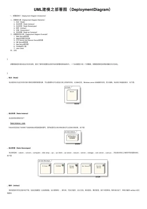
UML建模之部署图(DeploymentDiagram)⼀、部署图简介(Deployment Diagram Introduction)⼆、部署图元素(Deployment Diagram Elements)1、结点(Node)2、结点实例(Node Instance)3、结点类型(Node Stereotypes)4、物件(Artifact)5、连接(Association)6、结点容器(Node as Container)三、部署图项⽬⽰例(Deployment Diagram Example)1、Web Server服务器2、Web访问量分流设备3、FTP Server And Session Server服务器4、DB Server服务器5、App Server服务器6、FrieWall防⽕墙7、User Client四、总结)部署图描述的是系统运⾏时的结构,展⽰了硬件的配置及其软件如何部署到⽹络结构中。
⼀个系统模型只有⼀个部署图,部署图通常⽤来帮助理解分布式系统。
)、结点(Node)结点是存在与运⾏时的代表计算机资源的物理元素,可以是硬件也可以是运⾏其上的软件系统,⽐如64主机、Windows server 2008操作系统、防⽕墙等。
结点⽤三维盒装表⽰,如下图:、结点实例(Node Instance)结点实例名称格式如下Node Instance : node与结点的区别在于名称有下划线和结点类型前⾯有冒号,冒号前⾯可以有⽰例名称也可以没有⽰例名称,如下图、结点类型(Node Stereotypes)结点类型有:«cdrom», «cd-rom», «computer», «disk array», «pc», «pc client», «pc server», «secure», «server», «storage», «unix server», «user pc»,并在结点的右上⾓⽤不同的图标表⽰,如下图、物件(Artifact)物件是软件开发过程中的产物,包括过程模型(⽐如⽤例图、设计图等等)、源代码、可执⾏程序、设计⽂档、测试报告、需求原型、⽤户⼿册等等。
软件工程术语表软件工程术语表目录1. A (17)abstractclass:抽象类 (17)Abstraction:抽象 (17)accessmodifier:存取权限 (17)accessormethods:存取器方法 (17)acceptance:验收 (17)action:动作 (17)actionsequence:动作序列 (18)actionstate:动作状态 (18)activation激活: (18)activeclass:主动类 (18)activity:活动 (18)activeobject:主动对象 (18)activitygraph:活动图 (18)actor:主角 (19)actorclass:主角类 (19)actor-generalization:主角泛化关系) (19)actualparameter:实参 (19)adhocreview:临时评审 (19)aggregateclass:聚合类 (19)aggregation:聚合关系 (20)AmericanStandardCodeforInformationInterchange(ASCII):美国国家信息交换标准代码 (20)analysis:分析 (20)analysisclass:分析类 (20)analysis&design:分析设计 (20)analysismechanism:分析机制 (21)analysispattern:分析模式 (21)analyst:分析员 (21)API:应用程序编程接口 (21)APPC:高级程序间通信 (21)applicationprogramminginterface(API):应用程序编程接口(21)appraisal:评估 (21)architecturalbaseline:构架基线 (22)architecturalmechanism:构架机制 (22)architecturalpattern:构架模式 (22)architecturalview:构架视图 (22)architecture:构架 (22)artifact:工件 (23)artifactguidelines:工件指南 (23)ASCII:美国国家信息交换标准代码 (23)ASP:活动服务器页 (23)association:关联关系 (23)associationclass:关联类 (23)associationend:关联关系端 (23)asynchronousaction:异步动作 (24)asynchronousreview:异步评审 (24)attribute:属性 (24)2. B (24)baseclass:基类 (24)baseline:基线 (24)Bean (24)BeanInfo (25)behavior:行为 (25)behavioralfeature:行为特性 (25)behavioralmodelaspect:模型的行为侧重面 (25) betatestingBeta:测试 (25) binaryassociation:二元关联关系 (25) binding:绑定 (25)boundaryclass:边界类 (25)breakpoint:断点 (26)build:工作版本 (26)businessactor:业务主角 (26) businessactorclass业务主角类 (26) businesscreation:业务创建 (26) businessengineering:业务工程 (26) businessentity:业务实体 (26) businessimprovement:业务改进 (27) businessobjectmodel:业务对象模型 (27) businessmodeling:业务建模 (27) businessprocess:业务过程 (27) businessprocessengineering:业务过程工程 (27) businessreengineering:业务重建 (27) businessrule:业务规则 (28) businessusecase:业务用例 (28) businessuse-caseinstance:业务用例实例 (28) businessuse-casemodel:业务用例模型 (28) businessuse-casepackage:业务用例包 (28) businessuse-caserealization:业务用例实现 (28) businessworker:业务角色 (28)3. C (29)capsule封装体 (29)cardinality基数 (29)CBD (29)CCB (29)CDR (29)CGI (29)changecontrolboard(CCB)变更控制委员会 (30) changemanagement变更管理 (30)changerequest(CR)变更请求 (30)checklist检查表 (30)checkpoints检查点 (30)class类 (30)classdiagram类图 (30)classhierarchy类分层结构 (31)classlibrary类库 (31)classmethod类方法 (31)classifier分类器 (31)client客户端 (31)client/server客户机/服务器 (31)collaboration协作 (31)collaborationdiagram协作图 (32)COM (32)comment注释 (32)commit提交 (32)CommonGatewayInterface(CGI)公共网关接口 (32) CommonObjectRequestBrokerArchitecture(CORBA) (33) communicate-association通信关联关系 (33) communicationassociation通信关联关系 (33) component构件 (33)componentdiagram构件图 (33)componentmodel构件模型 (33)component-baseddevelopment(CBD)基于构件的开发 (34) compositeaggregation组装关系 (34) compositebean组合Bean (34)compositeclass组装类 (34)compositestate组合状态 (34)compositesubstate组合子状态 (34)composition组装 (35)concrete具体 (35)concreteclass具体类 (35)concurrency并行 (35)concurrentsubstate并行子状态 (35)configuration配置 (35)configurationitem配置项配置中的实体 (36) configurationmanagement配置管理 (36)construction构建 (36)constructor构造函数 (36)container容器 (36)containmenthierarchy容器分层结构 (37)context环境 (37)controlchart控制图 (37)controlclass控制类 (37)conversational会话式 (37)Cookie (37)CORBA (37)CR (38)criticaldesignreview(CDR)关键设计评审 (38)customer客户 (38)cycle周期 (38)4. D (38)database数据库 (38) databasemanagementsystem(DBMS)数据库管理系统 (38) datatype数据类型 (39)DBA数据库管理员 (39)DBCS双字节字符集 (39)DBMS数据库管理系统 (39)DCE分布式计算环境 (39)DCOM分布式对象模型 (39) deadlock死锁 (39)decisionrule决策规则 (39)defect缺陷 (39)defectchecklist缺陷检查表 (40) defectdensity缺陷密度 (40) defectlog缺陷日志 (40) definingmodel定义模型 (40) delegation委托 (40)deliverable可交付工件 (40)de-marshal串行化 (40) demilitarizedzone(DMZ)隔离带 (41) dependency依赖关系 (41) deployment部署 (41) deploymentdiagram部署图 (41) deploymentunit部署单元 (41) deploymentview部署视图 (41) derivedelement派生元素 (42) deserialize反串行化 (42)design设计 (42) designmechanism设计机制 (42) designpackage设计包 (43) designpattern设计模式 (43) designsubsystem设计子系统 (43) developer开发人员 (43) developmentcase开发案例 (43) developmentprocess开发过程 (44)device设备 (44)diagram图 (44)disjointsubstate互斥子状态 (44)DistributedComputingEnvironment(DCE)分布式计算环境(44)distributedprocessing分布式处理 (44)DLL动态链接库 (45)DMZ隔离带 (45)DNS域名服务 (45)document文档 (45)documentdescription文档说明 (45)documenttemplate文档模板 (45)domain领域 (45)domainmodel领域模型 (45)domainnameserver域名服务器 (45)double-bytecharacterset(DBCS)双字节字符集 (46)dynamicclassification动态分类 (46)dynamicinformation动态信息 (46)dynamiclinklibrary(DLL)动态链接库 (46)5. E (46)e-Business电子商务 (46)EJB (47)elaboration精化 (47)element元素 (47)encapsulation封装 (47)encloseddocument附带文档 (47)enhancementrequest扩展请求 (47)EnterpriseJavaBean(EJB) (47)entityclass实体类 (48)entryaction进入动作 (48)error错误 (48)ERP (48)event事件 (48)event-to-methodconnection事件-方法映射 (48) evolution演进 (48)evolutionary演进方式 (49) executablearchitecture可执行构架 (49) exitaction退出动作 (49)export导出 (49)expression表达式 (50)extend扩展 (50)extend-relationship扩展关系 (50)6. F (50)facade外观 (50)factory工厂 (50)fault故障 (50)feature特性 (51)field字段 (51)filetransferprotocol(FTP)文件传输协议 (51) finalstate最终状态 (51)fire击发 (51)Firewall防火墙 (51)flatten串行化 (51)focusofcontrol控制焦点 (52)follow-up跟踪 (52)formalreview正式评审 (52) formalparameter形参 (52)framework框架 (52)FTP文件传输协议 (52)FURPS (52)7. G (53)gateway:网关 (53)generalizableelement:可泛化元素 (53) generalization:泛化关系 (53)generation:代 (53)graphicaluserinterface(GUI):图形用户界面 (53) green-fielddevelopment:零起点开发 (53) guardcondition:警戒条件 (54)GUI (54)8. H (54)homepage主页 (54)HTML (54)HTMLbrowserHTML浏览器 (54)HTTP (54)HTTPrequestHTTP请求 (54)hyperlinks超链接 (55)hypertext超文本 (55) hypertextmarkuplanguage(HTML)超文本标记语言 (55) 9. I (55)IT(Informationtechnology) (55)IDE (55)IEEE (56)IIOP (56)internetORB间协议 (56)IMAP4 (56)implementation实施 (56) implementationinheritance实施继承 (56) implementationmechanism实施机制 (56) implementationmodel实施模型 (57) implementationpattern实施模式 (57)implementationsubsystem实施子系统 (57) implementationview实施视图 (57)import导入 (57)import-dependency导入依赖关系 (58)inception先启 (58)include包含 (58)include-relationship包含关系 (58)increment增量 (58)incremental递增 (58)informalreview非正式评审 (58)inheritance继承 (59)injectionrate缺陷率 (59)input输入 (59)inspection审查 (59)inspectioneffectiveness审查有效性 (59) inspectionefficiency审查效率 (59) inspectionpackage审查包 (59) inspectionsummaryreport审查总结报告 (60)inspector审查者 (60)issue问题 (60)issuelog问题日志 (60)instance实例 (60) integrateddevelopmentenvironment(IDE)集成开发环境 (60) integration集成 (60)integrationbuildplan集成构建计划 (61)interaction交互 (61)interactiondiagram交互图 (61)interface接口/界面 (61)interfaceinheritance接口继承 (61)internaltransition内部转移 (61)Internet互联网 (61)InternetInter-ORBProtocol(IIOP)InternetORB间协议 (62) InternetProtocol(IP)Internet协议 (62) InternetprotocoladdressInternet协议地址 (62)IP (62)IPnumberIP号码 (62)IPSec (62)IPSecurityProtocol(IPSec)IP安全协议 (63)ISAPI (63)ISO (63)ISP (63)iteration迭代 (63)10. J (63)JAR (63)Java (63)Javaarchive(JAR)Java档案文件 (64) JavaDatabaseConnectivity(JDBC)Java数据库连接 (64) JavaFoundationClasses(JFC)Java基础类 (64) JavaBean (64)JDBC (64)JDK (64)JFC (65)JIT (65)JVM (65)11. K (65)keymechanism关键机制 (65)keyword关键字 (65)12. L (65)LAN (65)layer层 (66)LDAP (66)link链接 (66)linkend链接端 (66)listener监听程序 (66)LocalAreaNetwork(LAN)局域网, (66) logicalview逻辑视图 (66)13. M (67)majordefect主要缺陷 (67)management管理 (67)marshal反串行化 (67) measurementdysfunction测量混乱 (67) mechanism机制 (67)message消息 (68)messaging消息传递 (68)metaclass元类 (68)meta-metamodel元-元模型 (68)metamodel元模型 (68)method方法 (68)methodcall方法调用 (69)metric度量 (69)MIB (69)milestone里程碑 (69)MIME (69)minordefect次要缺陷 (69)model模型 (69)modelaspect模型侧重面 (70) modelelaboration模型精化 (70) modelelement模型元素 (70) ModelViewController(MVC)模型视图控制器, (70) modelingconventions建模约定 (70)moderator评审组长 (70)module模块 (71)MOM (71)multipleclassification多重分类 (71) multipleinheritance多重继承 (71)multiplicity多重性 (71) MultipurposeInternetMailExtension(MIME) (71)multi-valued多值 (72)mutatormethods存取器方法 (72)MVC (72)MVS (72)14. N (72)n-aryassociation多元关联关系 (72)n-foldinspectionN重审查 (72)namespace名字空间 (73)NC (73)NCF (73)NNTP (73)node节点 (73)NSAPI (73)NT (73)15. O (74)object对象 (74)objectclass对象类 (74)objectdiagram对象图 (74)objectflowstate对象流状态 (74)objectlifeline对象生命线 (74)objectmodel对象模型 (74)ObjectRequestBroker(ORB)对象请求代理 (75)object-orientedprogramming(OOP)面向对象程序设计 (75)ODBCDriverODBC驱动程序 (75) ODBCDriverManagerODBC驱动程序管理器 (75)OLTP (75)OMG (75)onlinetransactionprocessing(OLTP)联机事务处理 (76)OO (76)OOP (76)OpenDataBaseConnectivity(ODBC)开放数据库连接标准 (76) operation操作 (76)operatingsystemprocess操作系统进程 (76)ORB (77)organizationunit组织单元 (77)originator发起者 (77)output输出 (77)outsidelink外部链接 (77)16. P (77)package包 (77)pairprogramming结对编程 (78)palette调色板 (78)parameter参数 (78)parameterconnection参数连接 (78) parameterizedelement参数化元素 (78)parent父 (78)parentclass父类 (78)participates参与 (79)partition分区 (79)passaround轮查 (79)pattern模式 (79)PDR (79)peerdeskcheck同级桌查 (80)peerreview同级评审 (80) peerreviewcoordinator同级评审协调者 (80)PERL (80)persistentobject永久对象 (80)PGP (80)phase阶段 (80)PKI (81)POP3 (81)Port端口 (81)post-condition后置条件 (81)PRA (81)PRD (81)pre-condition前置条件 (81) preliminarydesignreview(PDR)初步设计评审 (81) primitivetype基础类型 (82)private私有 (82)process进程、过程 (82)processassetslibrary过程资产库 (82) processowner过程拥有者 (82)processview进程视图 (82)processor处理器 (82)product产品 (83)productchampion产品推介人 (83)product-linearchitecture产品线构架 (83) productrequirementsdocument(PRD)产品需求文档 (83) project项目 (83)projectmanager项目经理 (83) ProjectReviewAuthority(PRA)项目评审委员会 (84) projection投影 (84)promotion晋升 (84)property特征 (84)property-to-propertyconnection特征-特征连接 (84) protected保护 (84)protocol协议 (85)prototype原型 (85)proxy代理 (85)pseudo-state伪状态 (85)publishedmodel已发布的模型 (85)17. Q (86)QA (86)qualifier限定词 (86)qualityassurance(QA)质量保证 (86)18. R (86)racecondition竞争状态 (86)rank等级 (86)rationale理由 (86)RDBMS (87)receiveamessage接收消息 (87)receiverobject接收方对象 (87)reception接收 (87)reference引用 (87)refinement改进 (87)relationship关系 (87)release发布版 (88)releasemanager发布经理 (88) RemoteMethodInvocation(RMI)远程方法调用 (88) RemoteProcedureCall(RPC)远程过程调用 (88) report报告 (88)repository储存库 (89)requirement需求 (89)requirementattribute需求属性 (89) requirements需求 (89) requirementsmanagement需求管理 (89) requirementstracing需求跟踪 (89) requirementtype需求类型 (89) resourcefile资源文件 (90) responsibility职责 (90)result结果 (90)resurrect反串行化 (90)review评审 (90)reuse复用 (90)rework返工 (90)RFC (90)RMI (91)RMIcompilerRMI编译器 (91) RMIregistryRMI注册表 (91)risk风险 (91)role角色 (91)RPC (91)RSA (91)rule规则 (91)19. S (92)S/MIME (92)sandbox沙箱 (92)scenario场景 (92) scopemanagement范围管理 (92) semanticvariationpoint语义分歧点 (92) sendamessage发送消息 (92) senderobject发送方对象 (93)SEPA (93)sequencediagram序列图 (93)serialize串行化 (93)server服务器 (93)Servlet (93)SET (94)severity严重性 (94)SHTTP (94)signal信号 (94)signature签名 (94)singleinheritance单重继承 (94)singlevalued单值 (94)single-bytecharacterset单字节字符集 (95)SMTP (95)SNMP (95)SocketSecure套接字保护 (95)SOCKS (95)softwarearchitecture软件构架 (95)SoftwareEngineeringProcessAuthority(SEPA)软件工程过程管理委员会 (96)softwareengineeringprocessgroup(SEPG)软件工程过程组 (96) softwarerequirement软件需求 (96)softwarerequirementsspecifications(SRS)软件需求规约 (96)softwarespecificationreview(SSR)软件规约评审 (96)specification规约 (96)SQL (96)SRR (96)SRS (97)SSL (97)SSR (97)stakeholder受益者,涉众 (97)stakeholderneed涉众需要 (97) stakeholderrequest涉众请求 (97)Startpage起始页 (97)state状态 (97)statechartdiagram状态图 (98)statemachine状态机 (98)staticartifact静态工件 (98) staticclassification静态分类 (98) staticinformation静态信息 (98)stereotype构造型 (98)stimulus激励 (99)structuralfeature结构特性 (99) structuralmodelaspect模型的结构侧重面 (99)stub桩模块 (99)subactivitystate子活动状态 (99)subclass子类 (99)submachinestate子机状态 (99)substate子状态 (100)subsystem子系统 (100)subtype子类型 (100)superclass超类 (100)supertype超类型 (100)supplier提供端 (100)swimlane泳道 (101)synchstate同步状态 (101) synchronousaction同步操作 (101) systemrequirementsreview(SRR)系统需求评审 (101) 20. T (102)taggedvalue标注值 (102)task任务 (102)TCP (102)TCP/IP (102)teamleader团队负责人 (102) technicalauthority技术权威 (102) Telnet (103)template模板 (103)test测试 (103)testcase测试用例 (103) testcoverage测试覆盖 (103) testdriver测试驱动程序 (103) testitem测试项 (103) testprocedure测试过程 (104) thinclient瘦客户机 (104)thread线程 (104)timeevent时间事件 (104) timeexpression时间表达式 (104) timingmark时间标记 (104) toolmentor工具向导 (104) traceability可追踪性 (105)trace追踪 (105)transaction事务 (105) transactionprocessing事务处理 (105) transientobject临时对象 (105) transition产品化/转移 (105)type类型 (106)typeexpression类型表达式 (106) typolist微错清单 (106)21. U (106)UI (106)UML (106)Unicode统一编码 (106) UnifiedModelingLanguage(UML)统一建模语言 (107) uniformresourcelocator(URL)统一资源定位符 (107) URL (107)usage用途 (107)usecase用例 (107)use-casediagram用例图 (107)use-caseinstance用例实例 (107)use-casemodel用例模型 (107)use-caserealization用例实现 (108)use-caseview用例视图 (108)userinterface(UI)用户界面 (108)utility实用工具 (108)22. V (108)validation确认 (108)value值 (109)variable变量 (109)verification验证 (109)version版本 (109)vertex顶点 (109)view视图 (109)viewelement视图元素 (110)viewprojection视图投影 (110)virtualmachine(VM)虚拟机 (110)visibility可见性 (110)vision前景 (110)visualprogrammingtool可视化编程工具 (110)VM (110)VPN (111)23. W (111)walkthrough走查 (111)webapplicationWeb应用程序 (111)webbrowserWeb浏览器 (111)webserverWeb服务器 (111)websiteWeb站点 (111)websystemWeb系统 (112)Widget窗口组件 (112)workbreakdownstructure工作细分结构 (112)workguideline工作指南 (112)workproduct工作产品 (112)worker角色 (112)workflow工作流程 (113)workflowdetail工作流程明细 (113)workspace工作区 (113)workstation工作站 (113)WorldWideWeb(WWW或Web)万维网 (113)WYSIWYG (113)24. X (114)XML (114)1.Aabstractclass:抽象类提供一组子类共有行为的类,但它本身并不具有实例。
软件工程中的软件模型与建模工具软件工程作为一门学科,主要研究软件系统的开发和维护过程。
而软件模型与建模工具则是软件工程中至关重要的一部分,用于描述、分析和设计软件系统。
本文将介绍软件工程中常见的软件模型以及相应的建模工具。
一、需求分析模型1.1. 数据流图(Data Flow Diagram, DFD)数据流图是一种表示系统功能和数据流动的图形化工具。
它将系统划分为各个模块,用箭头表示数据流向,用矩形表示处理功能。
数据流图可以清晰地描述系统的功能和数据流动,帮助软件工程师对系统需求进行分析和理解。
1.2. 用例图(Use Case Diagram)用例图是一种表示系统行为和角色之间关系的建模工具。
它描述了系统与用户、外部系统之间的交互情况。
用例图可以帮助软件工程师识别系统的功能需求,捕捉用户的操作场景,从而更好地进行需求分析和系统设计。
二、设计模型2.1. 类图(Class Diagram)类图是一种描述类、对象及其之间关系的建模工具。
它用于展示系统的静态结构,包括类之间的继承、关联、聚合等关系。
类图可以帮助软件工程师对系统的结构进行分析、设计和实现。
2.2. 时序图(Sequence Diagram)时序图是一种描述对象之间交互顺序的建模工具。
它展示了对象之间的消息传递,帮助软件工程师更好地理解系统的动态行为。
时序图可以用于详细描述系统的时序交互过程,指导软件开发过程。
三、实现模型3.1. 组件图(Component Diagram)组件图是一种描述系统内部组件之间关系的建模工具。
它展示了系统的结构和组件之间的依赖关系。
组件图可以帮助软件工程师理清系统的组件划分,指导代码编写和软件集成过程。
3.2. 部署图(Deployment Diagram)部署图是一种描述系统物理部署情况的建模工具。
它展示了系统组件在物理节点上的部署情况,帮助软件工程师进行系统的部署规划和资源配置。
四、建模工具4.1. UML(Unified Modeling Language)UML是一种广泛使用的软件建模语言,包括了多种建模工具,如用例建模、类建模、时序建模等。
deployment介绍Deployment是指将软件应用程序或系统部署到目标环境并使其可运行的过程。
在软件开发中,部署是整个开发生命周期的最后一个阶段,它涵盖了将开发的软件交付给最终用户使用的各种工作和任务。
本文将介绍部署的定义、重要性以及一些相关参考内容。
部署的定义:部署是将软件应用程序或系统从开发环境转移到生产环境的过程。
这包括安装、配置和运行应用程序所需的所有组件和依赖项,以及确保应用程序在目标环境中正常运行并能够满足用户需求。
部署的重要性:1. 提供软件的可用性:部署是将软件应用程序交付给用户的最后一步,在这一步骤中,软件将可供用户使用,从而实现业务价值。
2. 确保软件的正确性和稳定性:在部署过程中,会进行各种测试和验证,以确保软件在目标环境中能够正确运行,并保持稳定性和可靠性。
3. 满足用户需求:通过部署,可以根据用户需求对软件进行配置和定制,确保用户能够使用符合其需求和期望的功能。
4. 简化维护和升级:通过良好的部署过程,可以使软件的维护和升级变得更加容易和高效。
参考内容:1. 部署计划:在进行软件部署之前,制定详细的部署计划非常重要。
该计划应包括部署的时间表、环境准备工作、所需资源和人员配备等信息。
部署计划可以确保部署过程有序、高效地进行。
2. 自动化部署工具:有许多工具可以简化和自动化部署过程,例如Docker、Jenkins和Ansible等。
这些工具可以帮助开发团队更轻松地管理和部署应用程序。
3. 部署测试和验证:在进行正式部署之前,进行适当的测试和验证是非常重要的。
可以使用自动化测试工具和模拟环境来验证软件在目标环境中的运行情况。
4. 故障排除和监控:在部署后,需要确保软件能够正常运行并满足用户需求。
建立合适的故障排除和监控机制可以及时发现和解决问题,提高系统的可靠性和稳定性。
5. 部署文档:在部署过程中,制定和维护详细的部署文档非常重要。
这些文档可以记录配置和安装步骤,帮助团队成员理解和管理部署。
k8s deployment 概念所谓"k8s deployment概念",指的是在Kubernetes(简称k8s)平台上进行应用程序部署的方法和原理。
本文将详细介绍k8s deployment的基本概念、使用场景、部署步骤以及常见问题解答,旨在帮助读者快速了解和应用k8s deployment技术。
1. k8s deployment的基本概念Kubernetes是一个用于自动化容器的部署、扩展和管理的开源平台。
在k8s中,Deployment是一种资源对象,用于定义应用程序的部署方式。
它描述了应用程序的期望状态以及如何将实际状态与期望状态保持一致。
Deployment可以理解为应用程序的"蓝图",它包含了容器镜像的信息、副本数量、选定的节点等等。
通过使用Deployment,我们可以方便地进行应用程序的横向扩展、版本控制和滚动更新等操作,而无需手动操作每个节点。
2. k8s deployment的使用场景k8s Deployment适用于各种类型的应用程序,无论是Web应用、微服务架构、数据库还是消息队列。
以下是一些常见的使用场景:a. 高可用性和冗余:通过指定垂直或水平扩展的副本数,可以确保应用程序的高可用性。
当某个副本发生故障时,k8s会自动创建新的副本以保证应用程序的正常运行。
b. 滚动更新和回滚:在更新应用程序时,Deployment允许我们通过指定新的镜像版本来进行滚动更新,即逐步替换旧的副本。
如果新版本出现问题,我们还可以轻松地回滚到之前的版本。
c. 版本控制和发布策略:通过修改Deployment的配置,我们可以控制应用程序的发布策略,比如设置最大不可用副本数、最大并发数等。
这样可以避免过度负载和故障。
d. 动态扩缩容:使用Deployment,我们可以根据负载情况动态扩缩容应用程序。
k8s会根据预定义的规则自动增加或减少副本数量,以满足应用程序的需求。
一、什么是deploymentDeployment是英语单词"部署"的缩写形式,通常用于描述软件、应用程序或其他技术资源的安装、配置和准备工作。
在计算机领域中,deployment通常指的是将软件或代码部署到特定的服务器、设备或评台上,并进行相应的配置和测试工作,以确保其正常运行和使用。
二、deployment的类型在软件开发和信息技术领域中,deployment可以分为以下几种类型:1. 传统部署:传统部署是指将软件或代码部署到专门的服务器或设备上,由专业人员进行安装、配置和维护。
这种部署方式适用于大型企业和组织,通常需要耗费较多的时间和资源。
2. 云端部署:云端部署是指将软件或代码部署到云计算评台上,通过云服务提供商提供的资源和工具进行安装、配置和管理。
这种部署方式具有弹性和灵活性,可以根据需求进行扩展和缩减,适用于许多小型和中型企业。
3. 自动化部署:自动化部署是指利用自动化工具和技术,将软件或代码自动化地部署到目标服务器、设备或评台上,减少人工干预和提高部署效率。
常见的自动化部署工具包括Jenkins、Ansible、Chef等,可以实现持续集成和持续部署。
4. 容器部署:容器部署是指利用容器技术,将软件或代码打包成独立的容器,并在目标环境中进行部署和运行。
常见的容器评台包括Docker、Kubernetes等,可以实现快速部署和跨评台运行。
5. 移动设备部署:移动设备部署是指将移动应用程序部署到移动设备上,通过应用商店或企业分发管道进行安装和更新。
这种部署方式需要考虑到各种移动设备和操作系统的兼容性和安全性。
三、deployment的重要性在现代软件开发和信息技术领域中,deployment扮演着至关重要的角色,具有以下几点重要性:1. 提高效率:通过科学合理的部署流程和自动化工具,可以显著提高软件部署的效率和速度,减少人工干预和错误率。
2. 确保质量:良好的部署流程和测试机制可以确保软件或代码部署到目标环境后能够正常运行和使用,提高产品质量和用户体验。
deployment用法-回复什么是deployment?在计算机科学和软件工程领域,deployment(部署)是指将软件应用程序或系统转移到目标环境中进行使用的过程。
它通常涉及将应用程序安装、配置和验证,以确保能够在目标环境中正确地运行。
Deployment 的目标是使软件在目标环境中高效稳定地运行,并为用户提供所需的功能。
为什么需要deployment?软件开发团队在完成开发、测试和调试后,需要将其软件部署到生产环境中。
Deployment是将软件交付给最终用户的关键步骤。
在没有正确的deployment过程中,软件可能无法正常工作,或者用户无法使用所需的功能。
Deployment还有助于确保软件在目标环境中的稳定性、安全性和可扩展性。
Deployment的流程是什么?Deployment过程可以根据具体情况和需求有所不同,但通常包括以下步骤:1. 需求分析:首先,了解目标环境的需求和约束条件。
这可能涉及到硬件和软件的要求、网络配置、安全需求等。
2. 资源准备:为了在目标环境中部署软件,需要准备必要的资源。
这可能包括服务器、数据库、网络设备等。
3. 软件打包和安装:将软件打包成可执行文件或安装程序,并将其从开发环境传输到目标环境。
安装过程可能涉及到解压文件、复制文件、添加注册表项等。
4. 配置和初始化:根据目标环境的需求,对软件进行配置。
这可能包括设置参数、修改配置文件、修改数据库连接等。
5. 验证和测试:在完成配置后,需要验证软件在目标环境中的正确性和稳定性。
这可以通过运行各种测试来实现,包括功能测试、性能测试和安全性测试等。
6. 问题解决和优化:如果在验证和测试过程中发现问题,需要对其进行修复和优化。
这可能包括修改代码、更新配置和重新测试等。
7. 上线:在完成验证和优化后,可以将软件正式上线,并开始对最终用户提供服务。
Deployment的挑战是什么?Deployment可能面临一些挑战,包括:1. 平台兼容性:不同的目标环境可能具有不同的操作系统、硬件等,因此需要确保软件在不同平台上的兼容性和稳定性。
deployment介绍Deployment是指将软件应用程序或系统部署到可运行环境并使其可以正常运行的过程。
在软件开发中,deployment是开发周期的最后一个阶段,也是将软件从开发环境转移到实际运行环境的关键步骤。
本文将介绍deployment的定义、重要性、常见的deployment方式以及最佳实践。
Deployment定义:Deployment是指将软件应用程序或系统从开发环境转移到实际运行环境的过程。
它涉及到将软件代码打包并配置到可运行环境中,以确保系统可以正常运行。
Deployment涵盖了诸多方面,包括软件的安装、配置、测试、升级和维护等。
Deployment的重要性:Deployment是软件开发过程的最后一个关键阶段,它直接关系到软件的最终用户体验和系统的可用性。
一个成功的deployment过程可以确保软件在实际运行环境中高效稳定地运行,同时降低系统故障的风险。
此外,合理的deployment过程还可以最大程度地减少停机时间,保证软件业务的连续性,并降低维护成本。
常见的deployment方式:1. 手动部署:手动部署是最基本的部署方式,它涉及到人工复制和配置软件文件。
手动部署适用于小规模应用,但不适合大型复杂系统,因为它容易出错且耗时费力。
2. 脚本部署:脚本部署是通过使用自动化脚本来实现deployment过程。
通过编写脚本,可以自动完成软件安装、配置、启动等步骤,减少了手动部署的差错和工作量。
常见的脚本部署工具包括Shell脚本、Python脚本和Ansible等。
3. 容器化部署:容器化部署使用容器技术将软件打包成容器镜像,并在目标环境中运行。
容器化部署可以实现应用程序和其依赖的隔离,简化了部署过程,并提供了良好的可移植性和扩展性。
常见的容器化部署工具包括Docker和Kubernetes等。
Deployment最佳实践:1. 自动化:尽可能使用自动化工具和脚本来完成部署过程,避免手动操作和人为差错。
名词解释题汇总:1.软件是能够完成预定功能和性能,并对相应数据进行加工的程序和描述程序及其操作的文档。
2.信息隐藏模块中的软件设计决策信息封装起来的技术,只知道它的功能以及对外的接口,而不知它的内部细节3.对象对象是现实世界中个体或事物的抽象表示,是其属性和相关操作的封4.软件可维护性指软件被理解、改正、调整和改进的难易程度。
5.原型是目标软件系统的一个可操作模型,它实现了目标软件系统的某些重6.软件生存周期软件产品从形成概念开始,经过开发、运行(使用)和维护直到退役的全过程称为软件生存周期,包括软件定义、开发、使用和维护三部分。
7.白盒测试是已知产品内部工作过程,通过测试检验产品内部动作是否按照产品规格说明的规定正常进行8.预防性维护是为了进一步改善软件系统的可维护性和可靠性,并为以后的改进奠定基础。
9.构件图描述软件实现系统中各组成部件以及它们之间的依赖关系。
10.场景从单个执行者的角度观察目标软件系统的功能和外部行为。
11.计算机辅助软件工程(CASE) 将若干工具集成起来,与软件工程数据库和计算机系统构成一个支持软件开发的系统12.编程风格是在不影响性能的前提下,有效地编排和组织程序以提高可读性和可维性。
13.黑盒测试方法是已知产品应该具有的功能,通过测试检验每个功能是否都能正常使用;14.实体—关系图描述系统所有数据对象的组成和属性,描述数据对象之间关系的图形语言。
15.软件维护的副作用指由于维护或在维护过程中其他一些不期望的行为引入的错误,16.软件生存周期软件产品从形成概念开始,经过开发、运行(使用)和维护直到退役的全过程称为软件生存周期,包括软件定义、开发、使用和维护三部分。
17.结构化程序设计是一种程序设计技术,采用自顶向下逐步求精的设计方法和单入口单出口的控制构件。
18.软件过程(software process) 软件开发人员为开发和维护软件及相关产品所实施的一系列步骤,这些步骤涉及方法、工具及人的组织和行为。
一、概述在软件开发和运维中,部署(deployment)是一个极为重要的环节,它涉及到软件的安装、启动、更新和重启等操作。
而在部署过程中,重启策略是一个至关重要的环节,它关乎着软件系统的稳定性、可用性和性能。
本文将基于这一主题,探讨部署的重启策略的相关内容。
二、重启策略的定义重启策略是指软件在发生故障或需要更新时,部署系统采取的重启方式。
根据不同的需求和场景,重启策略可以有多种选择,例如在故障发生时自动重启、手动触发重启、按照一定的时间间隔定时重启等。
三、重启策略的分类根据重启的触发条件和方式,重启策略可以分为以下几种类型:1. 自动重启策略自动重启策略是指软件在发生故障时自动进行重启操作。
这种策略适用于对软件稳定性要求较高的场景,能够及时处理故障,并保证软件系统的持续稳定运行。
自动重启策略也需要考虑防止由于频繁重启导致系统负载过大的问题。
2. 手动触发重启策略手动触发重启策略是指在发生故障或需要重启时,需要人工干预才能进行重启。
这种策略需要有专门的管理人员来进行操作,因此适用于对软件可用性要求较高,但又需要保证重启操作的安全性和准确性的场景。
手动触发重启策略也需要考虑到人工干预可能会延迟故障的处理速度。
3. 定时重启策略定时重启策略是指按照一定的时间间隔或时间点来进行软件的重启操作。
这种策略适用于需要定期清理系统资源、防止内存泄漏等场景,能够保证软件系统的性能稳定性。
定时重启策略也需要考虑到重启时可能会造成一定的业务中断。
四、重启策略的选择与优缺点不同类型的重启策略都有其适用的场景和优缺点,因此在选择重启策略时需要综合考虑以下几个方面:1. 软件稳定性和可用性要求根据软件的实际稳定性和可用性要求来选择相应的重启策略。
对于对软件稳定性要求较高的场景,可以采用自动重启策略;对于对软件可用性要求较高的场景,可以考虑手动触发重启策略。
2. 业务影响和风险评估在选择重启策略时需要考虑到重启操作可能带来的业务影响和风险,以及业务对这些影响和风险的容忍程度。
kubectl get deployments的字段说明kubectl get deployments 是Kubernetes 命令行工具中用于查询部署(Deployment)资源的命令。
部署是Kubernetes 中一种资源对象,用于管理Pod 的创建和更新。
通过使用kubectl get deployments 命令,您可以获取部署的详细信息,包括部署的资源对象、名称、创建时间、更新时间、状态、标签等。
部署的资源对象(Resource Object)是Kubernetes 中的一个核心概念,用于定义和管理集群中的资源。
资源对象由一个或多个API 服务器处理,并生成相应的资源清单。
资源对象具有唯一的标识符,例如名称、UUID 等,可以方便地在集群中查找和引用。
部署的名称(Name)是用于标识部署的字符串。
部署名称应该遵循DNS subdomain 命名规范,以避免与其他资源冲突。
部署的创建时间(Creation Timestamp)和更新时间(Updated Timestamp)分别表示部署资源对象被创建和最近更新的时间。
这些时间戳可以帮助您了解部署的历史变化。
部署的状态(Status)描述了部署的当前状态,例如运行中、已暂停等。
部署的状态可以通过kubectl describe deployments 命令查看。
部署的标签(Labels)是一种附加到部署资源对象的字段,用于表示部署的属性。
标签可以由管理员或应用程序定义,用于区分不同的部署实例或满足应用程序的特定需求。
部署的容器(Container)是部署中运行的具体应用程序实例。
每个部署可以包含一个或多个容器,每个容器都运行在一个Pod 中。
部署的容器镜像(Container Image)是用于创建部署容器的基础镜像。
容器镜像通常存储在Docker 镜像仓库中,例如Docker Hub、私有仓库等。
部署的容器端口(Container Port)是容器暴露给外部网络的端口。
Deployment的典型应用场景一、概述Deployment,即部署,是指在开发环境中编写的应用程序或软件模块在生产环境中运行之前,将其打包、配置并部署到目标环境中的过程。
随着云计算、容器技术和微服务架构的普及,Deployment的应用场景越来越广泛,对于企业来说,选择合适的部署方式能够提高软件的质量、性能和可靠性,同时降低运维成本和风险。
二、Deployment的典型应用场景1.Web应用程序部署Web应用程序部署是Deployment最为常见的应用场景之一。
开发人员将Web应用程序打包后部署到服务器上,通过Web浏览器访问应用程序,实现用户与应用程序的交互。
在部署Web应用程序时,需要考虑服务器的硬件配置、操作系统、网络带宽等因素,以确保应用程序的性能和可用性。
2.移动应用程序部署移动应用程序部署是将移动应用程序打包后部署到移动设备上,供用户下载和使用。
在移动应用程序部署过程中,需要考虑不同设备的操作系统、屏幕分辨率和性能等因素,以确保应用程序能够在不同的设备和平台上流畅运行。
同时,移动应用程序的部署也需要考虑安全性和隐私保护等问题。
3.容器化应用程序部署容器化应用程序部署是使用容器技术将应用程序及其依赖项打包成一个独立的容器,然后部署到容器平台上。
容器化应用程序部署具有轻量级、可移植性等特点,可以快速部署和扩展应用程序。
在容器化应用程序部署中,需要考虑容器的资源限制、环境配置和安全性等问题。
4.微服务架构部署微服务架构是一种将应用程序拆分成多个小型服务的架构模式,每个服务都运行在独立的进程中,并使用轻量级通信协议进行通信。
在微服务架构部署中,每个服务都可以独立部署和扩展,提高了系统的可维护性和可靠性。
在部署微服务时,需要考虑服务的依赖关系、通信协议和负载均衡等问题。
5.大数据应用程序部署大数据应用程序部署是指将大数据处理任务打包并部署到大数据处理平台上。
大数据处理平台通常使用分布式计算技术对大规模数据进行处理和分析。
idea中deploymentDeployment(部署)是指将软件系统或应用程序从开发环境转移到生产环境的过程。
在软件开发过程中,deployment是一个关键的环节,它决定了软件的稳定性和可用性。
本文将从不同角度探讨deployment的重要性、流程和常见问题。
一、部署的重要性随着软件开发的持续发展,部署过程变得越来越复杂。
一个成功的部署过程可以确保软件在生产环境中运行稳定、高效。
部署的重要性主要体现在以下几个方面:1. 提高效率:通过自动化部署流程,可以减少手动操作和人为错误,提高部署效率。
部署过程的自动化可以避免重复劳动,节省时间和人力资源。
2. 降低风险:部署过程中会进行各种测试和验证,以确保软件在生产环境中的稳定性和安全性。
及时发现和解决问题,可以减少潜在风险和损失。
3. 确保一致性:通过标准化的部署流程,可以确保不同环境中的软件配置一致。
这样可以方便维护和管理,提高软件的可维护性。
二、部署的流程一个典型的部署流程包括以下几个阶段:1. 验证环境:在部署之前,需要验证目标环境是否满足软件的运行要求。
包括硬件和软件环境的检查,确保能够正确安装和运行软件。
2. 安装软件:根据部署需求,将软件包安装到目标环境中。
这包括解压、复制文件、创建数据库等操作。
3. 配置软件:根据实际需求,对软件进行配置。
包括修改配置文件、设置环境变量、创建用户等操作。
配置的目的是使软件能够适应不同环境的需求。
4. 启动服务:将软件启动起来,并进行必要的初始化。
启动过程中需要注意检查日志和错误信息,确保软件能够正常运行。
5. 进行测试:对部署后的软件进行功能测试、性能测试和安全测试,以确保软件在生产环境中的稳定性和可用性。
6. 监控和维护:部署完成后,需要对软件进行监控和维护。
包括监控系统性能、处理异常和故障、定期备份等操作。
三、常见问题和解决方法在实际部署过程中,常常会遇到各种问题。
下面列举了一些常见问题和解决方法:1. 依赖关系:软件通常会依赖其他组件或库。
Problem Statement:Implement Deployment diagram for capturing and representation, requirements of a system.Theory:Deployment diagrams are used to visualize the topology of the physical components of a system where the software components are deployed.So deployment diagrams are used to describe the static deployment view of a system. Deployment diagrams consist of nodes and their relationships.Purpose:The name Deployment itself describes the purpose of the diagram. Deployment diagrams are used for describing the hardware components where software components are deployed. Component diagrams and deployment diagrams are closely related.Component diagrams are used to describe the components and deployment diagrams shows how they are deployed in hardware.UML is mainly designed to focus on software artifacts of a system. But these two diagrams are special diagrams used to focus on software components and hardware components.So most of the UML diagrams are used to handle logical components but deployment diagrams are made to focus on hardware topology of a system. Deployment diagrams are used by the system engineers.The purpose of deployment diagrams can be described as:·Visualize hardware topology of a system.·Describe the hardware components used to deploy software components.·Describe runtime processing nodes.Elements of Deployment diagram:Node:A Node is either a hardware or software element. It is shown as a three-dimensional box shape, as shown below.Node Instance:A node instance can be shown on a diagram. An instance can be distinguished from anode by the fact that its name is underlined and has a colon before its base node type. An instance may or may not have a name before the colon. The following diagram shows a named instance of a computer.Node Stereotypes:A number of standard stereotypes are provided for nodes, namely «cdrom», «cd-rom»,«computer», «disk array», «pc», «pc client», «pc server», «secure», «server», «storage», «unix server», «user pc». These will display an appropriate icon in the top right corner of the node symbolArtifact:An artifact is a product of the software development process. That may include process models (e.g. use case models, design models etc), source files, executables, design documents, test reports, prototypes, user manuals, etc.An artifact is denoted by a rectangle showing the artifact name, the «artifact» keyword and a document icon, as shown below.Association:In the context of a deployment diagram, an association represents a communication path between nodes. The following diagram shows a deployment diagram for a network, depicting network protocols as stereotypes, and multiplicities at the association ends.How to Draw?Deployment diagram represents the deployment view of a system. It is related to the component diagram. Because the components are deployed using the deployment diagrams. A deployment diagram consists of nodes. Nodes are nothing but physical hardwares used to deploy the application.Deployment diagrams are useful for system engineers. An efficient deployment diagram is very important because it controls the following parameters·Performance·Scalability·Maintainability·PortabilitySo before drawing a deployment diagram the following artifacts should be identified:·Nodes·Relationships among nodesExample:Applications of Deployment Diagrams:Deployment diagrams are mainly used by system engineers. These diagrams are used to describe the physical components (hardware’s), their distribution and association.To clarify it in details we can visualize deployment diagrams as the hardware components/nodes on which software components reside.Software applications are developed to model complex business processes. Only efficientsoftware applications are not sufficient to meet business requirements. Business requirements can be described as to support increasing number of users, quick response time etc.To meet these types of requirements hardware components should be designed efficiently and in a cost effective way.So the usage of deployment diagrams can be described as follows:·To model the hardware topology of a system.·To model embedded system.·To model hardware details for a client/server system.·To model hardware details of a distributed application.·Forward and reverse engineering.Conclusion:Thus we have successfully studied and implemented deployment diagram of a system。