rfc3717.IP over Optical Networks A Framework
- 格式:pdf
- 大小:71.73 KB
- 文档页数:48

2022年职业考证-软考-网络规划设计师考试全真模拟易错、难点剖析B卷(带答案)一.综合题(共15题)1.单选题光纤通信提供了三种不同的拓扑结构,在光纤交换拓扑中N_PORT端口通过相关链路连接至()。
问题1选项A.NL_PORTB.FL_PORTC.F_PORTD.E_PORT【答案】C【解析】F_PORT:Fabric_Ports用于光纤交换环境下N_port之间的互连,从而所有节点都可以相互通信。
2.单选题Secure Shell(SSH) is a cryptographic network protocol for operating network services securely over an ( 1 ) network, Typical applications include remotecommand-line, login, and remote command execution, but any network service can be secured with SSH. The protocol works in the ( 2 ) model,which means that the connection in established by the SSH client connecting to the SSH server.The SSH client drives the connection setup process and uses public key cryptography to verify the ( 3 ) of the SSH server. After the setup phase the SSH protocol uses strong ( 4 ) encryption and hashing algorithms to ensure the privacy and integnity of the data that is exchanged between the client and server. There are serveral options that can be used for user authentication.The most common ones are passwords and ( 5 )key authentication.问题1选项A.encryptedB.unsecuredC.authorizedD.unauthorized问题2选项A.C/SB.B/SC.P2PD.distributed问题3选项A.capacityB.servicesC.applicationsD.identity问题4选项A.dynamicB.randomC.symmetricD.asymmetric问题5选项A.publicB.privateC.staticD.dynamic【答案】第1题:B第2题:A第3题:D第4题:C第5题:A【解析】第1题:安全外壳(SSH)是一种加密网络协议,用于在不安全的网络上安全地运行网络服务。

1.MPLS技术结合了ATM第2层的交换技术和IP第3层的路由技术。
2.LSR设备结构包括了两个平面,即数据平面和控制平面。
3.LSR转发报文依据栈顶标记。
(栈顶/栈底)4.LSR设备结构包括两个平面,标记转发信息表位于数据平面。
5.LSR设备结构包括了两个平面,即数据平面和控制平面。
6.VPN结构中,CE、PE、P的中英文含义分别是。
CE (Custom Edge Router),用户边缘路由器,直接与运营商网络相连PE (Provider Edge Router),运营商边缘路由器,与CE相连,主要负责VPN业务的接入。
P (Provider Router):运营商核心路由器,主要完成路由和快速转发功能。
7. BGP MPLS VPN中,RD的作用是在BGP发布VRF中的不可达路由信息时,会在地址前面加上RD,以便接收方PE区分来自不同VRF的路由信息。
,RT的作用是RT 是每个VRF表达自己的路由取舍及喜好的方式,采用BGP路由协议的UPDATE报文发布可达路由信息(NLRI)时,对其community属性进行扩展,成为RT。
使在PE上接收到来自不同VPN的两条相同路由时,可以区分出这两个不同的VPN。
8. LSP的建立方向是从数据流的下游至上游。
(上游/下游)9. 标记请求消息方向是从数据流的上游至下游。
(上游/下游)1.简述MPLS/BGP VPN报文的转发过程。
CE路由器将一个VPN分组发给入口PE路由器后;入口PE路由器查找对应的VRF表,从VRF表中得到VPN标签、初始外层标签以及到出口PE路由器的输出接口。
VPN分组被入口PE路由器打上两层标签之后,发送到相应LSP上的第一个P路由器。
骨干网中P路由器根据外层标签逐跳转发VPN分组,直至最后一个P路由器弹出外层标签,将只含有VPN标签的分组转发给出口PE路由器。
出口PE路由器根据VPN标签,查找MPLS路由表得到对应的输出接口,在弹出VPN标签后通过该接口将VPN分组发送给正确的CE路由器,从而实现了整个数据转发过程。
IP over OTN光网络路由与生存性探讨OTN(Optical Transport Network)光网络已经成为现代通信网络的骨干。
然而,由于物理链路的限制,OTN 网络在路由和生存性方面面临许多挑战。
IP(Internet Protocol) over OTN光网络路由和生存性的探讨是对这些挑战的分析,以及如何解决它们的讨论。
IP over OTN 光网络路由是指通过 IP 协议来传输在 OTN 网络中的数据包。
这种传输方式使得在不同 OTN 网络中传输数据变得更加便捷。
然而,尽管 IP 协议已经成为互联网标准,但在 OTN 网络中实现 IP 路由仍然是一个挑战。
由于 OTN 网络与传统互联网网络不同,因此需要开发新的路由协议。
目前,一个流行的协议是 MPLS-TP(Multiprotocol Label Switching-Transport Profile)。
这个协议将 MPLS 技术应用于 OTN 网络,以实现更高效的路由和更好的网络性能。
除了路由问题外,OTN 网络面临的另一个挑战是生存性。
OTN 网络中的物理链路存在断开的风险,而这种链路断开会导致网络故障。
为了提高 OTN 网络的生存性,需要采用多种技术,如光复用、多路径保护等。
其中,多路径保护可以在链路断开时自动切换到备用通道,以保证数据的传输。
这种技术的实现需要复杂的算法和硬件支持,并且需要更高的成本支出。
在总体上看,IP over OTN 光网络路由和生存性的探讨需要跨学科的合作和积极的研究。
随着 OTN 网络的不断发展,这种探讨变得越来越紧迫。
IP over OTN 光网络路由和生存性的研究可以促进技术的进步,提高网络性能,从而为用户提供更好的体验。

IP over WDM技术概述网络信息量爆炸式增长和IP技术的深入人心促进了宽带IP主干网的出现和发展,而宽带IP网络必须建立在现有的网络技术基础上,建立在当前最先进的网络传输技术基础上。
现在典型的相关技术有IP over ATM.IP overSDH、IP over WDM等。
IP over WDM由于具有其它相关技术所不具有的~系列优点而成为未来网络发展的方向。
一、什么是IP over WDMIP over WDM也称光因持网。
简言之,就是直接在光上运行的因特网。
其基本原理和工作方式是:在发送端,将不同波长的光信号组合(复用)送入一极光纤中传输,在接收端,又将组合光信号分开(解复用)并送入不同终端。
IP over WDM是一个真正的链路层数据网。
在其中,高性能路由器取代传统的基于电路交换概念的ATM和SDH电交换与复用设备,成为关键的统计复用设备。
高性能路由器通过光ADM或WDM耦合器直接连至WDM光纤。
由它控制波长接入,交换,选路和保护。
IP over WDM由于使用了指定的波长,在结构上将更加灵活,并具有向光交换和全光选路结构转移的可能。
二、IP over WDM帧结构IP over WDM的帧结构有两种形式;SDH帧格式牙和千兆以太网帧格式。
下面分别加以介绍。
1.SDH帧格式目前,主要网络再生设备大多采用SDH帧格式。
在使用SDH再生设备和转发器的网络内,来自路由器的IP分组必须装放在SDH帧内。
此种格式下报头载有信令和足够的网络管理信息,便于网络管理。
但相较而言,在路由器接口上针对SDH帧的拆装分割(SAR)处理耗时。
影响网络吞吐量和性能,且采用SDH帧格式的转发器和再生器造价昂贵。
许多公司现正在制定一种新的帧结构标准,称作“Fast-IP””或”SlimSDH”它提供SDH帧的许多功能,但在报头位置和如何使帧大小与分组大小匹配方面使用了更新的技术。
2千兆以太网帧格式目前,在局域网中主要采用千兆以太网帧结构。

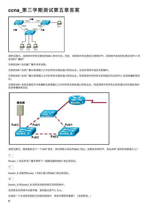
ccna_第三学期测试第五章答案请参见图⽰。
该⽹络中所有交换机的MAC 表均为空。
⽽且,该⽹络中的交换机已禁⽤STP。
该⽹络中会如何处理主机PC1 所发送的⼴播帧?交换机SW1 会拦截⼴播并丢弃该帧。
交换机SW1 会将⼴播从除源端⼝之外的所有交换机端⼝转发出去。
这会在⽹络中造成⽆限循环。
交换机SW1 会将⼴播从除源端⼝之外的所有交换机端⼝转发出去。
⽽该⽹络中的所有主机则通过向主机PC1 发送单播帧来回应。
交换机SW1 会将该通信作为单播帧从除源端⼝之外的所有交换机端⼝转发出去。
⽽该⽹络中的所有主机则通过向交换机SW1发送单播帧来回应请参见图⽰。
服务器发送了⼀个ARP 请求,询问其默认⽹关的MAC 地址。
如果未启⽤STP,则此ARP 请求的结果是什么?Router_1 会丢弃该⼴播并使⽤下⼀跳路由器的MAC 地址来回应。
Switch_A 会使⽤Router_1 的E0 接⼝的MAC 地址来回应。
Switch_A 和Switch_B 会将该消息持续泛洪到⽹络中。
该消息会在⽹络中反复传输,直到超出其TTL 为⽌。
在具有⼀个⽣成树实例的已收敛的⽹络中,将存在哪两项要素?(选择两项。
)每个⽹络有⼀个根桥所有⾮指定端⼝转发每个⾮根桥有⼀个根端⼝每个⽹段有多个指定端⼝每个⽹络有⼀个指定端⼝交换机使⽤哪两个条件来选择根桥?(选择两项。
)⽹桥的优先级交换速度端⼝数量基本MAC 地址交换机位置内存⼤⼩交换机通过哪两种⽅式使⽤BPDU 中的信息?(选择两项。
)⽤于在交换机之间协商中继链路⽤于设置冗余链路的双⼯模式⽤于确定到达根桥的最短路径⽤于通过在相连的交换机间共享桥接表来防⽌环路⽤于确定将哪些端⼝作为⽣成树的⼀部分转发帧下列哪两种说法正确描述了⽣成树拓扑中所⽤的BID?(选择两项。
)只有在下级BPDU 被发送出去后,它们才会被根桥发送出去。
它们包含⽹桥优先级和MAC 地址。
只有根桥会发送出BID。
它们被⽣成树拓扑中的交换机⽤来选举根桥。

【国家开放大学电大《计算机组网技术》机考10套题库及答案】【国家开放大学电大《计算机组网技术》机考10套题库及答案】国家开放大学电大《计算机组网技术》机考10套题库及答案盗传必究题库一试卷总分:100 答题时间:60分钟客观题一、单项选择题(共20题,共40分)1. 以下()信道介质不属于有线介质 D 微波 2. 没有进行路由器配置之前,路由表():A 是空表3. ()是络管理员手工配置的路由信息。
B 静态路由4. ()不是网络体系结构模型的重要组成元素:A 层次5. 网卡是用于哪一层的设备()A 物理层6. 以下()标准是无线局域网标准 C IEEE 802.11 7. 一个B类IP地址最多可容纳()主机。
D ***** 8. 物理地址的长度为()位D 48 9. ()命令能查看运行配置:D show running-config 10. 关于使用静态路由的优点,下列哪项描述正确?() A 安全性更高11. 交换机查MAC表发现数据帧目的MAC地址对应的转发端口号后直接转发数据帧到该端口;如果查表之后仍然不知道该目的MAC地址对应的端口号,交换机将帧转发到除了接收端口以外的所有端口,这是交换机的()功能。
B 转发12. 以下哪个选项是终端设备? A 智能手机13. 以下()协议不属于应用层 B TCP 14. ()不是一个私有IP地址:B 11.0.0.1 15. 用TCP/IP协议的网络在传输信息时,如果出了错误需要报告,采用的协议是()A ICMP 16. 一个私有C类IP地址地址范围是( )C 地址范围:192.168.0.1---192.168.255.254 17. 路由器的()模式允许管理员对路由器进行全面检查调试和测试。
B 特权18. 以下()不属于安全模型范畴D 安全边界19. 路由器之间使用以太网接口通信时不需要使用的命令是():C clock rate 时钟频率20. 路由器的()模式允许进行整个设备的整体配置。

PTN专业考试(试卷编号221)1.[单选题]IPV6的邻居发现机制要用到IPV6的_____地址A)节点链路地址B)节点链路地址本地链路地址C)全球可聚合单播地址答案:B解析:2.[单选题]针对南北向业务,在SRTP隧道上部署CC/CV检测机制,CV报文发送的时间间隔分别为A)3.3msB)10msC)100ms答案:B解析:3.[单选题]R860设备最大支持本地会话的ID为()A)1200B)1800C)1000答案:B解析:4.[单选题]C类地址最大可能子网位数是( )A)6B)7C)12D)14答案:A解析:5.[单选题]下列关于IP-FRR说法正确的是 (1.5分)A)A . IP-FRR保护是网间保护B)B . IP-FRR保护的原理的主用节点保护备用节点C)C . IP-FRR保护不能和VRRP保护同时使用D)D . IP-FRR保护的原理和VRRP保护原理一样答案:A解析:6.[单选题]IP地址190.233.27.13/16所在的网段地址是?B)190.233.0.0C)190.233.27.0D)190.233.27.1答案:B解析:7.[单选题]MPLS的标签可以嵌套多少层?A)1B)3C)10D)理论上无限答案:D解析:8.[单选题]在路由器中,如果去往同一目的地有多条路由,则决定最佳路由的因素有( )。
A)路由的优先级B)路由的发布者C)路由的cost值D)路由的生存时间答案:A解析:9.[单选题]为了满足子网寻径的需要,路由表中应包含的元素有A)源地址、子网掩码、目的网络地址B)源地址、目的网络地址、下一跳地址C)源地址、子网掩码、目的网络地址D)目的网络地址、子网掩码、下一跳地址答案:B解析:10.[单选题]在评估660的高阶槽位的UNILSP标签资源时,下面说法正确的是A)每个槽位的可用资源都一样B)UNI可用资源不受本槽位NNI接口上的串通资源影响C)因LSP一般是双向且对称的,因此评估时考察单项LSP资源即可D)单个槽位LSP单向标签资源最大为1024答案:C解析:11.[单选题]在PTN保护中的APS字节长度为A)2B)4D)8答案:B解析:12.[单选题]在MPLS VPN的连接模型中,VPN的构建、连接和管理工作是在________。

计算机⽹络⾃顶向下第七版第七章答案Computer Networking: A Top-Down Approach,7th Edition计算机⽹络⾃顶向下第七版Solutions to Review Questions and ProblemsChapter 7 Review Questions1.In infrastructure mode of operation, each wireless host is connected to the largernetwork via a base station (access point). If not operating in infrastructure mode, a network operates in ad-hoc mode. In ad-hoc mode, wireless hosts have noinfrastructure with which to connect. In the absence of such infrastructure, the hosts themselves must provide for services such as routing, address assignment, DNS-like name translation, and more.2.a) Single hop, infrastructure-basedb) Single hop, infrastructure-lessc) Multi-hop, infrastructure-basedd) Multi-hop, infrastructure-less3.Path loss is due to the attenuation of the electromagnetic signal when it travelsthrough matter. Multipath propagation results in blurring of the received signal at the receiver and occurs when portions of the electromagnetic wave reflect off objects and ground, taking paths of different lengths between a sender and receiver. Interference from other sources occurs when the other source is also transmitting in the samefrequency range as the wireless network.4.a) Increasing the transmission powerb) Reducing the transmission rate5.APs transmit beacon frames. An AP’s beacon frames will be transmitted over one ofthe 11 channels. The beacon frames permit nearby wireless stations to discover and identify the AP.6.False7.APs transmit beacon frames. An AP’s beacon frames will be transmitted over one ofthe 11 channels. The beacon frames permit nearby wireless stations to discover and identify the AP.8.False9.Each wireless station can set an RTS threshold such that the RTS/CTS sequence isused only when the data frame to be transmitted is longer than the threshold. This ensures that RTS/CTS mechanism is used only for large frames.10.No, there wouldn’t be any advantage. Suppose there are two stations that want totransmit at the same time, and they both use RTS/CTS. If the RTS frame is as long asa DATA frames, the channel would be wasted for as long as it would have beenwasted for two colliding DATA frames. Thus, the RTS/CTS exchange is only useful when the RTS/CTS frames are significantly smaller than the DATA frames.11.Initially the switch has an entry in its forwarding table which associates the wirelessstation with the earlier AP. When the wireless station associates with the new AP, the new AP creates a frame with the wireless station’s MAC address and broadcasts the frame. The frame is received by the switch. This forces the switch to update itsforwarding table, so that frames destined to the wireless station are sent via the new AP.12.Any ordinary Bluetooth node can be a master node whereas access points in 802.11networks are special devices (normal wireless devices like laptops cannot be used as access points).13.False14.“Opportunistic Scheduling” refers to matching the physical layer protocol to channelconditions between the sender and the receiver, and choosing the receivers to which packets will be sent based on channel condition. This allows the base station to make best use of the wireless medium.15.UMTS to GSM and CDMA-2000 to IS-95.16.The data plane role of eNodeB is to forward datagram between UE (over the LTEradio access network) and the P-GW. Its control plane role is to handle registration and mobility signaling traffic on behalf of the UE.The mobility management entity (MME) performs connection and mobility management on behalf of the UEs resident in the cell it controls. It receives UE subscription information from the HHS.The Packet Data Network Gateway (P-GW) allocates IP addresses to the UEs and performs QoS enforcement. As a tunnel endpoint it also performs datagram encapsulation/decapsulation when forwarding a datagram to/from a UE.The Serving Gateway (S-GW) is the data-plane mobility anchor point as all UE traffic will pass through the S-GW. The S-GW also performs charging/billing functions and lawful traffic interception.17.In 3G architecture, there are separate network components and paths for voice anddata, i.e., voice goes through public telephone network, whereas data goes through public Internet. 4G architecture is a unified, all-IP network architecture, i.e., both voice and data are carried in IP datagrams to/from the wireless device to several gateways and then to the rest of the Internet.The 4G network architecture clearly separates data and control plane, which is different from the 3G architecture.The 4G architecture has an enhanced radio access network (E-UTRAN) that is different from 3G’s radio access network UTRAN.18.No. A node can remain connected to the same access point throughout its connectionto the Internet (hence, not be mobile). A mobile node is the one that changes its point of attachment into the network over time. Since the user is always accessing theInternet through the same access point, she is not mobile.19.A permanent address for a mobile node is its IP address when it is at its homenetwork. A care-of-address is the one its gets when it is visiting a foreign network.The COA is assigned by the foreign agent (which can be the edge router in theforeign network or the mobile node itself).20.False21.The home network in GSM maintains a database called the home location register(HLR), which contains the permanent cell phone number and subscriber profileinformation about each of its subscribers. The HLR also contains information about the current locations of these subscribers. The visited network maintains a database known as the visitor location register (VLR) that contains an entry for each mobile user that is currently in the portion of the network served by the VLR. VLR entries thus come and go as mobile users enter and leave the network.The edge router in home network in mobile IP is similar to the HLR in GSM and the edge router in foreign network is similar to the VLR in GSM.22.Anchor MSC is the MSC visited by the mobile when a call first begins; anchor MSCthus remains unchanged during the call. Throughout the call’s duration and regardless of the number of inter-MSC transfers performed by the mobile, the call is routed from the home MSC to the anchor MSC, and then from the anchor MSC to the visited MSC where the mobile is currently located.23.a) Local recoveryb) TCP sender awareness of wireless linksc) Split-connection approachesChapter 7 ProblemsProblem 1Output corresponding to bit d 1 = [-1,1,-1,1,-1,1,-1,1]Output corresponding to bit d 0 = [1,-1,1,-1,1,-1,1,-1]Problem 2Sender 2 output = [1,-1,1,1,1,-1,1,1]; [ 1,-1,1,1,1,-1,1,1]Problem 3181111)1()1(111111)1()1(1112=?+?+-?-+?+?+?+-?-+?=d 181111)1()1(111111)1()1(1122=?+?+-?-+?+?+?+-?-+?=dProblem 4Sender 1: (1, 1, 1, -1, 1, -1, -1, -1)Sender 2: (1, -1, 1, 1, 1, 1, 1, 1)Problem 5a) The two APs will typically have different SSIDs and MAC addresses. A wirelessstation arriving to the café will associate with one of the SSIDs (that is, one of the APs). After association, there is a virtual link between the new station and the AP. Label the APs AP1 and AP2. Suppose the new station associates with AP1. When the new station sends a frame, it will be addressed to AP1. Although AP2 will alsoreceive the frame, it will not process the frame because the frame is not addressed to it. Thus, the two ISPs can work in parallel over the same channel. However, the two ISPs will be sharing the same wireless bandwidth. If wireless stations in different ISPs transmit at the same time, there will be a collision. For 802.11b, the maximum aggregate transmission rate for the two ISPs is 11 Mbps.b) Now if two wireless stations in different ISPs (and hence different channels) transmitat the same time, there will not be a collision. Thus, the maximum aggregatetransmission rate for the two ISPs is 22 Mbps for 802.11b.Problem 6Suppose that wireless station H1 has 1000 long frames to transmit. (H1 may be an AP that is forwarding an MP3 to some other wireless station.) Suppose initially H1 is the onlystation that wants to transmit, but that while half-way through transmitting its first frame, H2 wants to transmit a frame. For simplicity, also suppose every station can hear every other station’s signal (that is, no hidden terminals). Before transmitting, H2 will sense that the channel is busy, and therefore choose a random backoff value.Now suppose that after sending its first frame, H1 returns to step 1; that is, it waits a short period of times (DIFS) and then starts to transmit the second frame. H1’s second frame will then be transmitted while H2 is stuck in backoff, waiting for an idle channel. Thus, H1 should get to transmit all of its 1000 frames before H2 has a chance to access the channel. On the other hand, if H1 goes to step 2 after transmitting a frame, then it too chooses a random backoff value, thereby giving a fair chance to H2. Thus, fairness was the rationale behind this design choice.Problem 7A frame without data is 32 bytes long. Assuming a transmission rate of 11 Mbps, the time to transmit a control frame (such as an RTS frame, a CTS frame, or an ACK frame) is (256 bits)/(11 Mbps) = 23 usec. The time required to transmit the data frame is (8256 bits)/(11 Mbps) = 751DIFS + RTS + SIFS + CTS + SIFS + FRAME + SIFS + ACK= DIFS + 3SIFS + (3*23 + 751) usec = DIFS + 3SIFS + 820 usecProblem 8a) 1 message/ 2 slotsb) 2 messages/slotc) 1 message/slota)i) 1 message/slotii) 2 messages/slotiii) 2 messages/slotb)i) 1 message/4 slotsii) slot 1: Message A→ B, message D→ Cslot 2: Ack B→ Aslot 3: Ack C→ D= 2 messages/ 3 slotsiii)slot 1: Message C→ Dslot 2: Ack D→C, message A→ BRepeatslot 3: Ack B→ A= 2 messages/3 slotsProblem 10a)10 Mbps if it only transmits to node A. This solution is not fair since only A is gettingserved. By “fair” it m eans that each of the four nodes should be allotted equal number of slots.b)For the fairness requirement such that each node receives an equal amount of dataduring each downstream sub-frame, let n1, n2, n3, and n4 respectively represent the number of slots that A, B, C and D get. Now,data transmitted to A in 1 slot = 10t Mbits(assuming the duration of each slot to be t)Hence,Total amount of data transmitted to A (in n1 slots) = 10t n1Similarly total amounts of data transmitted to B, C, and D equal to 5t n2, 2.5t n3, and t n4 respectively.Now, to fulfill the given fairness requirement, we have the following condition:10t n1 = 5t n2 = 2.5t n3 = t n4Hence,n2 = 2 n1n3 = 4 n1n4 = 10 n1Now, the total number of slots is N. Hence,n1+ n2+ n3+ n4 = Ni.e. n1+ 2 n1 + 4 n1 + 10 n1 = Ni.e. n1 = N/17Hence,n2 = 2N/17n3 = 4N/17n4 = 10N/17The average transmission rate is given by:(10t n1+5t n2+ 2.5t n3+t n4)/tN= (10N/17 + 5 * 2N/17 + 2.5 * 4N/17 + 1 * 10N/17)/N= 40/17 = 2.35 Mbpsc)Let node A receives twice as much data as nodes B, C, and D during the sub-frame.Hence,10tn1 = 2 * 5tn2 = 2 * 2.5tn3 = 2 * tn4i.e. n2 = n1n3 = 2n1n4 = 5n1Again,n1 + n2 + n3 + n4 = Ni.e. n 1+ n1 + 2n1 + 5n1 = Ni.e. n1 = N/9Now, average transmission rate is given by:(10t n1+5t n2+ 2.5t n3+t n4)/tN= 25/9 = 2.78 MbpsSimilarly, considering nodes B, C, or D receive twice as much data as any other nodes, different values for the average transmission rate can be calculated.Problem 11a)No. All the routers might not be able to route the datagram immediately. This isbecause the Distance Vector algorithm (as well as the inter-AS routing protocols like BGP) is decentralized and takes some time to terminate. So, during the time when the algorithm is still running as a result of advertisements from the new foreign network, some of the routers may not be able to route datagrams destined to the mobile node.b)Yes. This might happen when one of the nodes has just left a foreign network andjoined a new foreign network. In this situation, the routing entries from the oldforeign network might not have been completely withdrawn when the entries from the new network are being propagated.c)The time it takes for a router to learn a path to the mobile node depends on thenumber of hops between the router and the edge router of the foreign network for the node.Problem 12If the correspondent is mobile, then any datagrams destined to the correspondent would have to pass through the correspondent’s home agent. The foreign agent in the network being visited would also need to be involved, since it is this foreign agent thatnotifies the correspondent’s home agent of the location of the correspondent. Datagrams received by the correspondent’s home agent would need to be encapsulated/tunneled between the correspondent’s home agent and for eign agent, (as in the case of the encapsulated diagram at the top of Figure 6.23.Problem 13Because datagrams must be first forward to the home agent, and from there to the mobile, the delays will generally be longer than via direct routing. Note that it is possible, however, that the direct delay from the correspondent to the mobile (i.e., if the datagram is not routed through the home agent) could actually be smaller than the sum of the delay from thecorrespondent to the home agent and from there to the mobile. It would depend on the delays on these various path segments. Note that indirect routing also adds a home agent processing (e.g., encapsulation) delay.Problem 14First, we note that chaining was discussed at the end of section 6.5. In the case of chaining using indirect routing through a home agent, the following events would happen: ?The mobile node arrives at A, A notifies the home agent that the mobile is now visiting A and that datagrams to the mobile should now be forwarded to thespecified care-of-address (COA) in A.The mobile node moves to B. The foreign agent at B must notify the foreign agent at A that the mobile is no longer resident in A but in fact is resident in Band has the specified COA in B. From then on, the foreign agent in A willforward datagrams it receives that are addressed to the mobile’s COA in A to t he mobile’s COA in B.The mobile node moves to C. The foreign agent at C must notify the foreign agent at B that the mobile is no longer resident in B but in fact is resident in C and has the specified COA in C. From then on, the foreign agent in B will forwarddatagrams it receives (from the foreign agent in A) that are addressed to themobile’s COA in B to the mobile’s COA in C.Note that when the mobile goes offline (i.e., has no address) or returns to its home network, the datagram-forwarding state maintained by the foreign agents in A, B and C must be removed. This teardown must also be done through signaling messages. Note that the home agent is not aware of the mobile’s mobility beyond A, and that the correspondent is not at all aware of the mobil e’s mobility.In the case that chaining is not used, the following events would happen: ?The mobile node arrives at A, A notifies the home agent that the mobile is now visiting A and that datagrams to the mobile should now be forwarded to thespecified care-of-address (COA) in A.The mobile node moves to B. The foreign agent at B must notify the foreign agent at A and the home agent that the mobile is no longer resident in A but infact is resident in B and has the specified COA in B. The foreign agent in A can remove its state about the mobile, since it is no longer in A. From then on, thehome agent will forward datagrams it receives that are addressed to the mobile’sCOA in B.The mobile node moves to C. The foreign agent at C must notify the foreign agent at B and the home agent that the mobile is no longer resident in B but in fact is resident in C and has the specified COA in C. The foreign agent in B canremove its state about the mobile, since it is no longer in B. From then on, thehome agent will forward datagrams it receives that are addressed to the mobile’sCOA in C.When the mobile goes offline or returns to its home network, the datagram-forwarding state maintained by the foreign agent in C must be removed. This teardown must also bedone through signaling messages. Note that the home agent is always aware of the mobile’s cu rrent foreign network. However, the correspondent is still blissfully unaware of the mobile’s mobility.Problem 15Two mobiles could certainly have the same care-of-address in the same visited network. Indeed, if the care-of-address is the address of the foreign agent, then this address would be the same. Once the foreign agent decapsulates the tunneled datagram and determines the address of the mobile, then separate addresses would need to be used to send the datagrams separately to their different destinations (mobiles) within the visited network.Problem 16If the MSRN is provided to the HLR, then the value of the MSRN must be updated in the HLR whenever the MSRN changes (e.g., when there is a handoff that requires the MSRN to change). The advantage of having the MSRN in the HLR is that the value can be provided quickly, without querying the VLR. By providing the address of the VLR Rather than the MSRN), there is no need to be refreshing the MSRN in the HLR.。

CCNA初级网络工程师知识点自测CCNA初级网络工程师知识点自测1.【单选题】10分| RIP协议中可以使用多种方法防止路由环路,以下选项中不属于防环机制的是A 垂直反转B 水平分割C 最大跳计数D 反向路由毒化2.【单选题】10分| Cisco路由器操作系统IOS有三种命令模式,其中不包括A 用户模式B 特权模式C 远程连接模式D 配置模式3.【单选题】10分| EIGRP协议是思科私有协议,它采用的路由度量方法是A 以跳数做为度量B 链路开销与带宽成反比C 根据链路负载动态计算D 根据带宽延迟等多种因素来计算4.【单选题】10分| 三层交换机根据_____对数据包进行转发A MAC地址B IP地址C 端口号D 应用协议5.【单选题】10分| 按照802.1d协议,当交换机端口处于_____状态时,既可以学习MAC帧中的源地址,也可以把收到的MAC帧转发到适当端口A 阻塞B 学习C 转发D 监听6.【单选题】10分| DHCP客户端启动时会向网络发出一个Discover 包来请求IP地址该数据包的目标地址为A 0.0.0.0B 127.0.0.1C 192.168.255.255D 255.255.255.2557.【单选题】10分| 广域网和局域网之间的差异不仅在于他们所覆盖的地理范围不同,而且还在于他们的__不同A 所支持的通信量B 所提供的应用服务C 所使用的传输介质D 所采用的协议8.【单选题】10分| 在TCP/IP网络中,ARP的协议数据单元贝封装在___中发送。
A UDP报文段B TCP报文段C IP数据报D 以太帧9.【单选题】10分| 网络管理平台中拓扑结构发现是ICMP的经典应用之一,该方法所使用的报文是A 路由重定向报文B 时间戳请求报文C 回送请求报文D 超时报文10.【单选题】10分| RIPv1不支持CIDR,对于运行RIPv1协议的路由器,不能设置的网络地址是A 10.16.0.0/8B 172.16.0.0/16C 172.22.0.0/18D 192.168.1.0/24。
专利名称:路由网络中的容错通信
专利类型:发明专利
发明人:M·T·玛萨,D·A·迪昂,R·欧帕弗斯基申请号:CN200680033111.6
申请日:20060911
公开号:CN101263686A
公开日:
20080910
专利内容由知识产权出版社提供
摘要:一种用于向应用提供多个节点之间的容错网络通信的方法,包括:通过在多个节点之间耦合的多个网络上提供多个初始通信通路;从应用接收发送节点上的数据分组,该发送节点该多个节点中的一个,数据分组由应用添加多个节点中的一个上的地址;以及在多个初始通信通路中为该数据分组选择第一所选通路,其中该第一所选通路是优选通路。
申请人:微软公司
地址:美国华盛顿州
国籍:US
代理机构:上海专利商标事务所有限公司
代理人:陈斌
更多信息请下载全文后查看。
解决IP网络传输层优化问题从国家基础网络建设的角度来看,建立高质量的IP网络的主要问题集中在网络层、数据链路层和物理层。
很显然,物理层应该采用能够保障网络带宽需求的光纤技术,通过光纤构建IP骨干网。
网络层采用IP协议已是既成事实,无论传输数据或是语音、视频信号都可以封装在IP数据包内通过IP网络进行传输,那么当运营商的网络选择和优化问题都集中到数据链路层的实现,IP层与物理层之间究竟该采用什么传输方式?如何对IP网络传输层进行优化? 传统的IP传输层技术及其优化 在实际应用中,传统的IP网络传输层通常采用以下四种技术:IPoverATM、IPoverSDH、IPoverOptical、千兆以太网(GE)。
IP over ATM IP与ATM的结合,也就是在ATM网络上支持IP技术,并构造骨干传输网。
当前有两种技术实现方式:重叠技术和集成技术。
重叠技术是将IP网络层协议重叠在ATM之上,即ATM网与现有的IP网重叠。
目前采用这种技术的有ATM论坛定义的LANE、IET F定义的IPOA及ATM论坛定义的MPOA,但是这种方式传递IP 的效率不高。
集成技术是将IP路由器的智能和管理性能集成到AT M交换机形成一体化平台,仅要求标识IP地址,无须ATM的地址解析协议,简化了ATM的路由选择功能,提高了IP转发效率,同时保留了路由的灵活性。
以IETF的多协议标签交换(MPLS)和Cisc o公司的标记交换(TagSwitching)技术为代表。
目前发展比较迅速的是MPLS技术。
它的网络控制是在传统路由协议的基础上,通过简单标记分配协议来代替复杂的ATM信令协议,预先为MPLS边缘路由器建立直达的数据连接。
在数据通信过程中,中间的MPLS交换机根据转发信息库只作信元交换功能,加快了数据包的转发速度,减少了延迟及抖动,有利于支持实时业务。
MPLS具有VC合并的功能,能解决重叠模型的问题。
IP over ATM可以利用ATM的QoS特性对网络进行优化,保证网络的服务质量,适用于多种业务,有很好的扩充性能,有良好的网络流量管理和拥塞控制性能,适用于一般的IP骨干网边缘多业务的接续。
1、七号信令链路初始定位程序用于信令链路首次启动(如接通后)和链路发生故障后进行恢复时的定位。
A.正确B.错误正确答案:A2、在七号信令中,当在信令链路的接收端检测出拥塞条件时,则启动流量控制程序。
链路拥塞的接收端以适当的链路状态信号单元通知远端的发送端这一条件,并停止证实所有的输入消息信号单元。
A.正确B.错误正确答案:A3、在七号信令中,管理阻断过程是一种信令业务管理功能,用于信令网的维护和测试目的。
当对某条链路进行管理阻断后,该链路上将没有消息传递。
A.正确B.错误正确答案:B4、在七号信令中,预防循环重发校正方法(PCR方法)是只有肯定证实,无否定证实的前向纠错方法,适用于单向传输时延大于15ms的链路。
A.正确B.错误正确答案:A5、CK是校验字段,用以完成差错检测功能,它对LI字段后至CK字段前的消息内容进行校验。
A.正确B.错误正确答案:B6、起始定位程序用于信令链路首次启动(如接通后)和链路发生故障后进行恢复时的定位。
A.正确正确答案:A7、信号单元中的前向序号是发送信号单元时的顺序编号,后向序号是被证实信号单元的顺序编号。
它们的取值范围为0~128。
A.正确B.错误正确答案:B8、管理阻断过程是一种信令业务管理功能,用于信令网的维护和测试目的。
当对某条链路进行管理阻断后,该链路上将没有消息传递。
A.正确B.错误正确答案:B9、如果对某条信令链路实行管理阻断而会导致目的地不可达,则该管理阻断将不会被允许进行。
A.正确B.错误正确答案:A10、允许传递消息是由某信令点发出,通知与其相邻各信令点该信令点可达。
A.正确B.错误正确答案:B11、信令路由组测试消息是由信令转接点发出,以测试与其相邻的信令点路由是否可用。
A.正确B.错误正确答案:B12、STP路由数据中为保证消息的可靠转发,有时到LSTP同一级或下一级设备的路由,可以向LSTP的上一级设备设置迂回路由。
A.正确正确答案:B13.No.7消息信令单元结构上采用形式。
光同步数字传输网上传送IP的相关问题分析
李雄文;方亮;张淑芳
【期刊名称】《计算机应用研究》
【年(卷),期】2001(018)009
【摘要】首先对IP over SDH的基本原理和技术特点进行了简要论述;然后讨论了IP over SDH与路由器的关系、对SDH设备的要求、简化数据链路协议(SDL)等相关问题.
【总页数】3页(P46-48)
【作者】李雄文;方亮;张淑芳
【作者单位】国家教育部科技发展中心;大唐电信成都光通信分公司;国家教育部科技发展中心
【正文语种】中文
【中图分类】TN914.332
【相关文献】
1.光同步数字传输技术讲座:第四章光同步数字体系应用的有关问题 [J], 陈国骢;黄兆荣
2.基于光同步数字传输网的IP传送技术 [J], 方亮;徐智勇;张淑芳;汪剑
3.光同步数字传输网的传输性能分析 [J], 高凌云
4.光同步数字传输技术讲座第一章光同步数字体系基本概念 [J], 黄兆荣
5.光同步数字传输网上直接传送IP原理及特点分析 [J], 崔雪梅
因版权原因,仅展示原文概要,查看原文内容请购买。
朗讯科技在为中国建设端到端全光网络
刘海声
【期刊名称】《电信工程技术与标准化》
【年(卷),期】2000(000)006
【总页数】1页(P52)
【作者】刘海声
【作者单位】朗讯科技中国光网络部
【正文语种】中文
【中图分类】TN929.1
【相关文献】
1.端到端的全光网络 [J], 李宜艳;姜帆;申艳秋
2.构建时间、空间、网络层次三纬度集成端到端安全网络--华为"i3安全"端到端安全解决方案 [J], 华为技术有限公司
3.面向全光网络的端到端无源链路智能管控 [J], 贾永华;马文学;于丽嘉
4.构建时间、空间、网络层次三纬度集成端到端安全网络--华为"i3安全"端到端安全解决方案 [J],
5.构建层时间、空间.网络层次三纬度集成端到端安全网络——华为“i3安全”端到端安全解决方案 [J],
因版权原因,仅展示原文概要,查看原文内容请购买。
Network Working Group B. Rajagopalan Request for Comments: 3717 Consultant Category: Informational J. Luciani Marconi Communications D. Awduche MCI March 2004 IP over Optical Networks: A FrameworkStatus of this MemoThis memo provides information for the Internet community. It doesnot specify an Internet standard of any kind. Distribution of thismemo is unlimited.Copyright NoticeCopyright (C) The Internet Society (2004). All Rights Reserved.AbstractThe Internet transport infrastructure is moving towards a model ofhigh-speed routers interconnected by optical core networks. Thearchitectural choices for the interaction between IP and opticalnetwork layers, specifically, the routing and signaling aspects, are maturing. At the same time, a consensus has emerged in the industry on utilizing IP-based protocols for the optical control plane. This document defines a framework for IP over Optical networks,considering both the IP-based control plane for optical networks aswell as IP-optical network interactions (together referred to as "IP over optical networks").Rajagopalan, et al. Informational [Page 1]Table of Contents1. Introduction . . . . . . . . . . . . . . . . . . . . . . . . . 32. Terminology and Concepts . . . . . . . . . . . . . . . . . . . 43. The Network Model. . . . . . . . . . . . . . . . . . . . . . . 8 3.1. Network Interconnection. . . . . . . . . . . . . . . . . 83.2. Control Structure. . . . . . . . . . . . . . . . . . . . 114. IP over Optical Service Models and Requirements. . . . . . . . 13 4.1. Domain Services Model. . . . . . . . . . . . . . . . . . 13 4.2. Unified Service Model. . . . . . . . . . . . . . . . . . 14 4.3. Which Service Model? . . . . . . . . . . . . . . . . . . 154.4. What are the Possible Services?. . . . . . . . . . . . . 165. IP transport over Optical Networks . . . . . . . . . . . . . . 16 5.1. Interconnection Models . . . . . . . . . . . . . . . . . 17 5.2. Routing Approaches . . . . . . . . . . . . . . . . . . . 18 5.3. Signaling-Related. . . . . . . . . . . . . . . . . . . . 215.4. End-to-End Protection Models . . . . . . . . . . . . . . 236. IP-based Optical Control Plane Issues. . . . . . . . . . . . . 25 6.1. Addressing . . . . . . . . . . . . . . . . . . . . . . . 25 6.2. Neighbor Discovery . . . . . . . . . . . . . . . . . . . 27 6.3. Topology Discovery . . . . . . . . . . . . . . . . . . . 28 6.4. Protection and Restoration Models. . . . . . . . . . . . 29 6.5. Route Computation. . . . . . . . . . . . . . . . . . . . 30 6.6. Signaling Issues . . . . . . . . . . . . . . . . . . . . 326.7. Optical Internetworking. . . . . . . . . . . . . . . . . 347. Other Issues . . . . . . . . . . . . . . . . . . . . . . . . . 35 7.1. WDM and TDM in the Same Network. . . . . . . . . . . . . 35 7.2. Wavelength Conversion. . . . . . . . . . . . . . . . . . 36 7.3. Service Provider Peering Points. . . . . . . . . . . . . 36 7.4. Rate of Lightpath Set-Up . . . . . . . . . . . . . . . . 36 7.5. Distributed vs. Centralized Provisioning . . . . . . . . 37 7.6. Optical Networks with Additional ConfigurableComponents . . . . . . . . . . . . . . . . . . . . . . . 38 7.7. Optical Networks with Limited Wavelength ConversionCapability . . . . . . . . . . . . . . . . . . . . . . . 388. Evolution Path for IP over Optical Architecture. . . . . . . . 399. Security Considerations. . . . . . . . . . . . . . . . . . . . 41 9.1. General Security Aspects . . . . . . . . . . . . . . . . 429.2. Security Considerations for Protocol Mechanisms. . . . . 4310. Summary and Conclusions. . . . . . . . . . . . . . . . . . . . 4411. Informative References . . . . . . . . . . . . . . . . . . . . 4412. Acknowledgments. . . . . . . . . . . . . . . . . . . . . . . . 4513. Contributors . . . . . . . . . . . . . . . . . . . . . . . . . 4614. Authors’ Addresses . . . . . . . . . . . . . . . . . . . . . . 4715. Full Copyright Statement . . . . . . . . . . . . . . . . . . . 48 Rajagopalan, et al. Informational [Page 2]1. IntroductionOptical network technologies are evolving rapidly in terms offunctions and capabilities. The increasing importance of opticalnetworks is evidenced by the copious amount of attention focused onIP over optical networks and related photonic and electronicinterworking issues by all major network service providers,telecommunications equipment vendors, and standards organizations. In this regard, the term "optical network" is used generically inpractice to refer to both SONET/SDH-based transport networks, as well as switched optical networks (including all-optical networks).It has been realized that optical networks must be survivable,flexible, and controllable. There is, therefore, an ongoing trend to introduce intelligence in the control plane of optical networks tomake them more versatile [1]. An essential attribute of intelligent optical networks is the capability to instantiate and route opticallayer connections in real-time or near real-time, and to providecapabilities that enhance network survivability. Furthermore, there is a need for multi-vendor optical network interoperability, when an optical network may consist of interconnected vendor-specific optical sub-networks.The optical network must also be versatile because some serviceproviders may offer generic optical layer services that may not beclient-specific. It would therefore be necessary to have an optical network control plane that can handle such generic optical services. There is general consensus in the industry that the optical networkcontrol plane should utilize IP-based protocols for dynamicprovisioning and restoration of optical channels within and acrossoptical sub-networks. This is based on the practical view thatsignaling and routing mechanisms developed for IP traffic engineering applications could be re-used in optical networks. Nevertheless, the issues and requirements that are specific to optical networking must be understood to suitably adopt and adapt the IP-based protocols.This is especially the case for restoration, and for routing andsignaling in all-optical networks. Also, there are different viewson the model for interaction between the optical network and clientnetworks, such as IP networks. Reasonable architectural alternatives in this regard must be supported, with an understanding of theirrelative merits.Thus, there are two fundamental issues related to IP over opticalnetworks. The first is the adaptation and reuse of IP control plane protocols within the optical network control plane, irrespective ofthe types of digital clients that utilize the optical network. The Rajagopalan, et al. Informational [Page 3]second is the transport of IP traffic through an optical networktogether with the control and coordination issues that arisetherefrom.This document defines a framework for IP over optical networkscovering the requirements and mechanisms for establishing an IP-centric optical control plane, and the architectural aspects of IPtransport over optical networks. In this regard, it is recognizedthat the specific capabilities required for IP over optical networks would depend on the services expected at the IP-optical interface as well as the optical sub-network interfaces. Depending on thespecific operational requirements, a progression of capabilities ispossible, reflecting increasingly sophisticated interactions at these interfaces. This document therefore advocates the definition of"capability sets" that define the evolution of functionality at theinterfaces as more sophisticated operational requirements arise.This document is organized as follows. In the next section,terminology covering some basic concepts related to this frameworkare described. The definitions are specific to this framework andmay have other connotations elsewhere. In Section 3, the networkmodel pertinent to this framework is described. The service modeland requirements for IP-optical, and multi-vendor opticalinternetworking are described in Section 4. This section alsoconsiders some general requirements. Section 5 considers thearchitectural models for IP-optical interworking, describing therelative merits of each model. It should be noted that it is not the intent of this document to promote any particular model over theothers. However, particular aspects of the models that may make one approach more appropriate than another in certain circumstances aredescribed. Section 6 describes IP-centric control plane mechanismsfor optical networks, covering signaling and routing issues insupport of provisioning and restoration. The approaches described in Section 5 and 6 range from the relatively simple to thesophisticated. Section 7 describes a number of specialized issues in relation to IP over optical networks. Section 8 describes a possible evolution path for IP over optical networking capabilities in termsof increasingly sophisticated functionality that may be supported as the need arises. Section 9 considers security issues pertinent tothis framework. Finally, the summary and conclusion are presented in Section 10.2. Terminology and ConceptsThis section introduces terminology pertinent to this framework and some related concepts. The definitions are specific to thisframework and may have other interpretations elsewhere.Rajagopalan, et al. Informational [Page 4]WDMWavelength Division Multiplexing (WDM) is a technology that allowsmultiple optical signals operating at different wavelengths to bemultiplexed onto a single optical fiber and transported in parallelthrough the fiber. In general, each optical wavelength may carrydigital client payloads at a different data rate (e.g., OC-3c, OC-12c, OC- 48c, OC-192c, etc.) and in a different format (SONET,Ethernet, ATM, etc.). For example, there are many commercial WDMnetworks in existence today that support a mix of SONET signalsoperating at OC-48c (approximately 2.5 Gbps) and OC-192(approximately 10 Gbps) over a single optical fiber. An opticalsystem with WDM capability can achieve parallel transmission ofmultiple wavelengths gracefully while maintaining high systemperformance and reliability. In the near future, commercial denseWDM systems are expected to concurrently carry more than 160wavelengths at data rates of OC-192c and above, for a total of 1.6Tbps or more. The term WDM will be used in this document to refer to both WDM and DWDM (Dense WDM).In general, it is worth noting that WDM links are affected by thefollowing factors, which may introduce impairments into the opticalsignal path:1. The number of wavelengths on a single fiber.2. The serial bit rate per wavelength.3. The type of fiber.4. The amplification mechanism.5. The number and type of nodes through which the signals pass before reaching the egress node or before regeneration.All these factors (and others not mentioned here) constitute domainspecific features of optical transport networks. As noted in [1],these features should be taken into account in developing standardsbased solutions for IP over optical networks.Optical cross-connect (OXC)An OXC is a space-division switch that can switch an optical datastream from an input port to a output port. Such a switch mayutilize optical-electrical conversion at the input port andelectrical-optical conversion at the output port, or it may be all-optical. An OXC is assumed to have a control-plane processor thatimplements the signaling and routing protocols necessary forcomputing and instantiating optical channel connectivity in theoptical domain.Rajagopalan, et al. Informational [Page 5]Optical channel trail or LightpathAn optical channel trail is a point-to-point optical layer connection between two access points in an optical network. In this document,the term "lightpath" is used interchangeably with optical channeltrail.Optical mesh sub-networkAn optical sub-network, as used in this framework, is a network ofOXCs that supports end-to-end networking of optical channel trailsproviding functionality like routing, monitoring, grooming, andprotection and restoration of optical channels. The interconnection of OXCs in this network can be based on a general mesh topology. The following sub-layers may be associated with this network:(a) An optical multiplex section (OMS) layer network: The opticalmultiplex section layer provides transport for the opticalchannels. The information contained in this layer is a datastream comprising a set of optical channels, which may have adefined aggregate bandwidth.(b) An optical transmission section (OTS) layer network: This layerprovides functionality for transmission of optical signalsthrough different types of optical media.This framework does not address the interaction between the opticalsub-network and the OMS, or between the OMS and OTS layer networks.Mesh optical network (or simply, "optical network")A mesh optical network, as used in document, is a topologicallyconnected collection of optical sub-networks whose node degree mayexceed 2. Such an optical network is assumed to be under the purview of a single administrative entity. It is also possible to conceiveof a large scale global mesh optical network consisting of thevoluntary interconnection of autonomous optical networks, each ofwhich is owned and administered by an independent entity. In such an environment, abstraction can be used to hide the internal details of each autonomous optical cloud from external clouds.Optical internetworkAn optical internetwork is a mesh-connected collection of opticalnetworks. Each of these networks may be under a differentadministration.Rajagopalan, et al. Informational [Page 6]Wavelength continuity propertyA lightpath is said to satisfy the wavelength continuity property if it is transported over the same wavelength end-to-end. Wavelengthcontinuity is required in optical networks with no wavelengthconversion feature.Wavelength pathA lightpath that satisfies the wavelength continuity property iscalled a wavelength path.Opaque vs. transparent optical networksA transparent optical network is an optical network in which optical signals are transported from transmitter to receiver entirely in the optical domain without OEO conversion. Generally, intermediateswitching nodes in a transparent optical network do not have accessto the payload carried by the optical signals.Note that amplification of signals at transit nodes is permitted in transparent optical networks (e.g., using Erbium Doped FiberAmplifiers << EDFAs).On the other hand, in opaque optical networks, transit nodes maymanipulate optical signals traversing through them. An example ofsuch manipulation would be OEO conversion which may involve 3Roperations (reshaping, retiming, regeneration, and perhapsamplification).Trust domainA trust domain is a network under a single technical administrationin which adequate security measures are established to preventunauthorized intrusion from outside the domain. Hence, it may beassumed that most nodes in the domain are deemed to be secure ortrusted in some fashion. Generally, the rule for "single"administrative control over a trust domain may be relaxed in practice if a set of administrative entities agree to trust one another toform an enlarged heterogeneous trust domain. However, to simplifythe discussions in this document, it will be assumed, without loss of generality, that the term trust domain applies to a singleadministrative entity with appropriate security policies. It should be noted that within a trust domain, any subverted node can sendcontrol messages which can compromise the entire network. Rajagopalan, et al. Informational [Page 7]FlowIn this document, the term flow will be used to signify the smallest non-separable stream of data, from the point of view of an endpointor termination point (source or destination node). The reader should note that the term flow is heavily overloaded in contemporarynetworking literature. In this document, we will consider awavelength to be a flow, under certain circumstances. However, ifthere is a method to partition the bandwidth of the wavelength, then each partition may be considered a flow, for example using timedivision multiplexing (TDM), it may be feasible to consider eachquanta of time within a given wavelength as a flow.Traffic TrunkA traffic trunk is an abstraction of traffic flow traversing the same path between two access points which allows some characteristics and attributes of the traffic to be parameterized.3. The Network Model3.1. Network InterconnectionThe network model considered in this memo consists of IP routersattached to an optical core internetwork, and connected to theirpeers over dynamically established switched optical channels. Theoptical core itself is assumed to be incapable of processingindividual IP packets in the data plane.The optical internetwork is assumed to consist of multiple opticalnetworks, each of which may be administered by a different entity.Each optical network consists of sub-networks interconnected byoptical fiber links in a general topology (referred to as an optical mesh network). This network may contain re-configurable opticalequipment from a single vendor or from multiple vendors. In the near term, it may be expected that each sub-network will consist ofswitches from a single vendor. In the future, as standardizationefforts mature, each optical sub-network may in fact contain optical switches from different vendors. In any case, each sub-networkitself is assumed to be mesh-connected internally. In general, itcan be expected that topologically adjacent OXCs in an optical meshnetwork will be connected via multiple, parallel (bi-directional)optical links. This network model is shown in Figure 1.In this environment, an optical sub-network may consist entirely ofall-optical OXCs or OXCs with optical-electrical-optical (OEO)conversion. Interconnection between sub-networks is assumed to beimplemented through compatible physical interfaces, with suitable Rajagopalan, et al. Informational [Page 8]optical-electrical conversions where necessary. The routers thathave direct physical connectivity with the optical network arereferred to as "edge routers" with respect to the optical network. As shown in Figure 1, other client networks (e.g., ATM) may also connect to the optical network.The switching function in an OXC is controlled by appropriatelyconfiguring the cross-connect fabric. Conceptually, this may beviewed as setting up a cross-connect table whose entries are of theform <input port i, output port j>, indicating that the data streamentering input port i will be switched to output port j. In thecontext of a wavelength selective cross-connect (generally referredto as a WXC), the cross-connect tables may also indicate the inputand output wavelengths along with the input and output ports. Alightpath from an ingress port in an OXC to an egress port in aremote OXC is established by setting up suitable cross-connects inthe ingress, the egress and a set of intermediate OXCs such that acontinuous physical path exists from the ingress to the egress port. Optical paths tend to be bi-directional, i.e., the return path from the egress port to the ingress port is typically routed along thesame set of intermediate interface cards as the forward path, butthis may not be the case under all circumstances.Rajagopalan, et al. Informational [Page 9]Optical Network+---------------------------------------+| || Optical Subnetwork |+---------+ | +-----------------------------------+ || | | | +-----+ +-----+ +-----+ | || IP | | | | | | | | | | || Network +-UNI --+-+ OXC +------+ OXC +------+ OXC + | || | | | | | | | | | | |+---------+ | | +--+--+ +--+--+ +--+--+ | || +----|------------|------------|----+ || | | | || INNI INNI INNI |+---------+ | | | | || | | +----+------+ | +-------+----+ || IP + UNI- | | +-----+ | | || Network | | | Optical | | Optical | || | | |Subnetwork +---INNI---+ Subnetwork | |+---------+ | | | | | || +-----+-----+ +------+-----+ || | | |+-------+-----------------------+-------+| |ENNI ENNI| |+-------+-----------------------+-------+| || Optical Network || |+-------+-----------------------+-------+| |UNI UNI| |+-----+----- --+ +-----+------+| | | || Other Client | |Other Client|| Network | | Network || (e.g., ATM) | | |+- ------------+ +------------+Figure 1: Optical Internetwork ModelMultiple traffic streams exiting from an OXC may be multiplexed onto a fiber optic link using WDM technology. The WDM functionality mayexist outside of the OXC, and be transparent to the OXC. Or, thisfunction may be built into the OXC. In the later case, the cross-connect table (conceptually) consists of pairs of the form, <{input port i, Lambda(j)}, {output port k, Lambda(l)}>. This indicates that Rajagopalan, et al. Informational [Page 10]the data stream received on wavelength Lambda(j) over input port i is switched to output port k on Lambda(l). Automated establishment oflightpaths involves setting up the cross-connect table entries in the appropriate OXCs in a coordinated manner such that the desiredphysical path is realized.Under this network model, a switched lightpath must be establishedbetween a pair of IP routers before the routers can transfer usertraffic among themselves. A lightpath between IP routers maytraverse multiple optical networks and be subject to differentprovisioning and restoration procedures in each network.The IP-based control plane issue for optical networks pertains to the design of standard signaling and routing protocols for provisioningand restoration of lightpaths across multiple optical networks.Similarly, IP transport over optical networks involves establishingIP reachability and seamlessly constructing forwarding paths from one IP endpoint to another over an optical network.3.2. Control StructureThere are three logical control interfaces identified in Figure 1.These are the client-optical internetwork interface, the internalnode-to-node interface within an optical network (between OXCs indifferent sub-networks), and the external node-to-node interfacebetween nodes in different optical networks. These interfaces arealso referred to as the User-Network Interface (UNI), the internalNNI (INNI), and the external NNI (ENNI), respectively.The distinction between these interfaces arises out of the type andamount of control information flow across them. The client-opticalinternetwork interface (UNI) represents a service boundary betweenthe client (e.g., IP router) and the optical network. The client and server (optical network) are essentially two different roles: theclient role requests a service connection from a server; the serverrole establishes the connection to fulfill the service request --provided all relevant admission control conditions are satisfied.Thus, the control flow across the client-optical internetworkinterface is dependent on the set of services defined across it andthe manner in which the services may be accessed. The service models are described in Section 4. The NNIs represent vendor-independentstandardized interfaces for control flow between nodes. Thedistinction between the INNI and the ENNI is that the former is aninterface within a given network under a single technicaladministration, while the later indicates an interface at theadministrative boundary between networks. The INNI and ENNI may thus differ in the policies that restrict control flow between nodes. Rajagopalan, et al. Informational [Page 11]Security, scalability, stability, and information hiding areimportant considerations in the specification of the ENNI. It ispossible in principle to harmonize the control flow across the UNIand the NNI and eliminate the distinction between them. On the other hand, it may be required to minimize flow of control information,especially routing-related information, over the UNI; and even overthe ENNI. In this case, UNI and NNIs may look different in somerespects. In this document, these interfaces are treated asdistinct.The client-optical internetwork interface can be categorized aspublic or private depending upon context and service models. Routing information (i.e., topology state information) can be exchangedacross a private client-optical internetwork interface. On the other hand, such information is not exchanged across a public client-optical internetwork interface, or such information may be exchanged with very explicit restrictions (including, for example abstraction, filtration, etc). Thus, different relationships (e.g., peer orover-lay, Section 5) may occur across private and public logicalinterfaces.The physical control structure used to realize these logicalinterfaces may vary. For instance, for the client-opticalinternetwork interface, some of the possibilities are:1. Direct interface: An in-band or out-of-band IP control channel(IPCC) may be implemented between an edge router and each OXC towhich it is connected. This control channel is used forexchanging signaling and routing messages between the router andthe OXC. With a direct interface, the edge router and the OXC it connects to are peers with respect to the control plane. Thissituation is shown in Figure 2. The type of routing and signaling information exchanged across the direct interface may varydepending on the service definition. This issue is addressed inthe next section. Some choices for the routing protocol are OSPF or ISIS (with traffic engineering extensions and additionalenhancements to deal with the peculiar characteristics of optical networks) or BGP, or some other protocol. Other directory-basedrouting information exchanges are also possible. Some of thesignaling protocol choices are adaptations of RSVP-TE or CR-LDP.The details of how the IP control channel is realized is outsidethe scope of this document.2. Indirect interface: An out-of-band IP control channel may beimplemented between the client and a device in the optical network to signal service requests and responses. For instance, amanagement system or a server in the optical network may receiveservice requests from clients. Similarly, out-of-band signaling Rajagopalan, et al. Informational [Page 12]may be used between management systems in client and opticalnetworks to signal service requests. In these cases, there is no direct control interaction between clients and respective OXCs.One reason to have an indirect interface would be that the OXCsand/or clients do not support a direct signaling interface.+---------------------------+ +---------------------------+| | | || +---------+ +---------+ | | +---------+ +---------+ || | | | | | | | | | | || | Routing | |Signaling| | | | Routing | |Signaling| || | Protocol| |Protocol | | | | Protocol| |Protocol | || | | | | | | | | | | || +-----+---+ +---+-----+ | | +-----+---+ +---+-----+ || | | | | | | || | | | | | | || +--+-----------+---+ | | +--+-----------+---+ || | | | | | | || | IP Layer +....IPCC.....+ IP Layer | || | | | | | | || +------------------+ | | +------------------+ || | | || Edge Router | | OXC |+---------------------------+ +---------------------------+Figure 2: Direct Interface3. Provisioned interface: In this case, the optical network services are manually provisioned and there is no control interactionsbetween the client and the optical network.Although different control structures are possible, furtherdescriptions in this framework assume direct interfaces for IP-optical and optical sub-network control interactions.4. IP over Optical Service Models and RequirementsIn this section, the service models and requirements at the UNI andthe NNIs are considered. Two general models have emerged for theservices at the UNI (which can also be applied at the NNIs). Thesemodels are as follows.4.1. Domain Services ModelUnder the domain services model, the optical network primarily offers high bandwidth connectivity in the form of lightpaths. Standardizedsignaling across the UNI (Figure 1) is used to invoke the followingservices:Rajagopalan, et al. Informational [Page 13]。