TPM Interface Specification (TIS)
- 格式:pdf
- 大小:581.41 KB
- 文档页数:70

Ground SupportYour success is our concernTo buy, sell, rent or trade-in this product please click on the link below:/TIC-Tel-Instruments-TB-2100-transponder-DME-Mode-S-Test-Set.aspx> Ideal for flightline calibration checks and troubleshooting > Performs precision Pitot-Static leak tests> Two-instrument combination with optional ranges > Correction cards for all analog instruments > Fully portable and self-contained(No electric or external pressure sources needed)> Lightweight plastic case for portability1811D Pitot static> Compact fiberglass case allows unit to fit in tight quarters > Performs on board instrument calibration checks > Performs precision Pitot-Static leak tests> Three-instrument capability for analog units with optional ranges> Correction cards for all analog instruments> Operates from 115/230 VAC 50-400 Hz (1811HA)> Fully portable, self-contained(No electric or external pressure sources required)> Vacuum & pressure hand pumps installed on both models (1811GA & 1811HA)1811GA-1811HA Pitot static> Transducer Technology provides the highest accuracy and best long-term stability available for line maintenance equipment> Menu-driven operator interface provides protection of instruments under test with programmable limits on the following parameters: • Altitude (feet or meters) • Airspeed (knots or km/hr)• Rate of Climb (ft/min or m/min) • Mach (mach)> Leak testing mode displays leak rates in ft/min, knots/min and metric equivalent units> Meets .0030 inHg accuracy on static channelDPS350w w w .b a r fi e l d i n> Fully automated unit > Handheld remote control> Database capable of saving the limit data of up to thirty different aircraft and stored in a battery backed memory> GO TO GROUND feature automatically and safely depressurizes both systems to ambient pressure > Compatible with any Centronics standard parallel interface printer of 80 or 132-column width> PC programmable via RS 232 using optional Test Program Manager (TPM) software kit > Available with an IEEE 488 Connector> Meets .0030 inHg accuracy on static channelDPS500> Three independent pressure control channels for altitude, air speed and angle of attack> High accuracy resonant silicon sensors on all channels > Internal pressure and vacuum generation, high pump reliability> GO TO GROUND feature automatically and safely depressurizes both systems to ambient pressure > Manual or stored test sequence operation> RS232 port for PC control or test data transfer > Limits protection for aircraft instruments> Compact and lightweight for quick and easy portability > Meets .0030 inHg accuracy on static channelADTS 206ADS-B Compliant> ADS-B and TIS Test features> Tests transponder (Modes A, C and S)> Allows simulation of ATCRBS and Mode S Intruders for TCAS testing > Simulates DME distance and velocity> Performs transponder tests required by FAR Appendix F Part 43> Download test data to PC via an RS-232 interface > 2-year limited warranty; 5 & 10-year available> Generates ILS signals to ICAO Annex 10 CAT III precision> Checks VOR, GS, LOC, MB, VHF COMM, Flight Director & Autopilot > Operates in shop, on ramp and in cockpit> Tests antenna-to-antenna or direct connect coax> US and European frequencies with 8.33 kHz channels > Meets requirements of MIL-PRF-28800F > Built-in NICAD battery and charger > 2-year limited warranty> Two independent, non-coherent RF channels for Mode S testing > Tests the latest Mode S Capabilities• Automatic Dependent Surveillance Broadcast (ADS-B) • Extended Squitter• Elementary (ES) and Enhanced Surveillance (EHS) • Traffic Information Systems (TIS)> Color LCD display features wide viewing angle> Touch-sensitive screen allows quick setup of test parameters > Easy to navigate menus require minimal training to operate > Continuous display of critical measurements including power, pulse parameters, percent reply and frequency > 2-year limited warranty> Permits ICAO Annex 10 CAT III ILS ramp check certification > Checks VOR, GS, LOC, MB, Flight Director & Autopilot > Dual VOR/LOC/GS frequencies > Separate and simultaneous MB/ILS > Dual extended-range variable ILS > Easy one-man operation> Fully adjustable functions allowing precise testing and measurements > 2-year limited warranty; 5 & 10-year availableT-30D VOR/ILS/MB Ramp T est SetT-36C Cat III Nav/Comm T est SetTR-220 Multi-Function T est SetTB-2100 ATC/DME T est SetADS-B Compliantw w w .b a r fi e l d i n c.c o mPre-T est Probes>> The pre-testers are employed to verify the integrity of the pitot test adapter, hoses and air data test set prior to connection to the aircraft. The probe is inserted into the pitot test adapter while connected to the hose and air data test set. By applying pneumatic pressure, the entire assembly (tester, hoses & adapters) are checked for leakage.Pitot T est Adapters>> The pitot test adapter body is of solid uni-body construction. There is no metal to metal contact between pitot tube and test adapters. Seals and spacers inside the adapter body ensure a leak free connection. They are easily exchanged withoutspecial tools. Optional high temperature seals and spacers can be installed upon request.Static T est Adapters>> Static test adapters provide a connecting seal at the aircraft’s static ports. The means of attachment depend on the aircraft type.Installation and removal of our adapters takes just seconds.Air Data Accessory Kits>> Air data accessory kits contain all the required test adapters and hoses to connect the air data test set to the aircraft type for which the kit is designed.Also included as standard equipment are pre-test adapters, seal kits and lubrication fluid.Depending on the need, additional equipment such as control consoles and suspension arms are a part of the kit.RVSM Air data accessory kits are available.Cable AdapterP/N 101-00932 and 101-00939For GE Engine CF6-80A, A1 and C2Cable AdapterP/N 101-00933For GE Engine CF6 and CF6-50CT12A Cable tensiometerThe CT12A provides accurate readings in pounds over awide range of cable sizes from 1/16” to 1/4” (US Std).Operating temperatures range from 14°F (-10°C) to 120°F (50°C).> Meets new OEM specificationsw w w .b a r fi e l d in c .c o mTT1000A T urbine temperature test set> Automatically compensates for ambient temperature at test lead connection junction point or indicates cold junction temperature> Thermocouple and lead resistance measurements to 0.01 ohm and insulation measurements up to two (2) megohms > Large, 9mm (0.35”) high character, 3 1/2-digit liquid crystal display with pre-programmed legends> Range: from 0 to 1000º C certified, -60 to 1160º C extended > Measures and displays values of CH/AL thermocouple in terms of degrees Celsius (ºC) temperature> Simulates CH/AL thermocouple with or without simulated system lead resistance> Accuracy: Typical measurement error at ambient (25ºC) less than ± 1ºCP/N 101-00902-908> Calibration device for mounted aircraft compass > Rugged, durable and lightweight > Accurate to within ± 1º> Hand-held and portable> 5-foot monopod support included > Protective carrying case included> Manufactured with lightweight aluminium-alloy > Field tests aircraft fluid pressure systems > Provides for both leak and calibration tests> Pressure source for pressure transducers, warning switches & direct reading pressure gauges > Applicable for shop or line use> No electrical or pneumatic source needed > Analog and digital gauges available> Hand-held, portable, rugged, durable and lightweight> Panel switch selector for 100, 200 and 500 volt test potentials > Push to test probe button activation > Simple forward reading scale > Absolutely no shock hazards > Sensitive operational amplifier > Solid-state circuitrySC063 Sight compass2311FA Pressure tester2471F Megohmmeter> Completely self contained DC capacitance fuelquantity test system> Capability to bench check aircraft fuel quantity system components> Capacitance simulation in the range of 0 to 400 pF with infinite resolution> 4 1/2-digit liquid crystal display> Digital readout of quantity system output in (volts, lbs., ratio, etc.)> Interchangeable aircraft interface modules > Powered from common AA batteries> Provisions for bench-testing of system components > State-of-the-art low battery drain circuitry> Maximum ease of operation and maintenanceDC400AFuel quantity test set>> Aircraft specific modules include:BAe Jetstream 32BAe Jetstream 41 Bell Helicopter 214STBell Helicopter 412SP, 412HP Canadair CL600, CL601Dehavilland DHC8Embraer EMB-120Hawker Beechcraft King Air C-99 & 1900Hawker Beechcraft 125-800Hawker Beechcraft 125-1000Piper Meridian SAAB SF-340Swearingen SJ30-2DC400 adapter modulesThe interchangeable adapter modules customize the DC400A to interface directly with specific aircraft without the need for an external cable.w w w .b a r fi e l din c .c o mDFQ40KFuel quantity test set> Microprocessor based> Completely self contained AC capacitance fuel quantity test system> Measures capacitance, insulation, DC voltage, resistance and distance to fault> Capacitance simulation and indicator testing > Custom multi-line backlit graphic display> Direct keypad entry of Tank and Comp simulation values > Uses all existing fuel quantity cables> Uses new generation of Smart Cables to perform Automated Test Routines> Calibration date available from display with user alerts to approaching calibration date > Numerous user prompts> Powered from common C-cell batteries with auto-off feature to conserve energyAC adapter modulesContrary to popular belief, there is no “black magic” in trouble-shooting and calibrating fuel capacitance systems, but only if you have the right equipment.>> Aircraft modules available for ATR AirbusBell Helicopter Boeing Canadair Casa Cessna Dehavilland EmbraerEurocopter/Aerospatiale/MBB Fairchild Falcon Jet Fokker Gulfstreamaircraft using AC fuel systems include:Hawker Beechcraft (C-90, A100) Beechjet Hawker-Siddeley IAI Learjet LockheedMcDonnell-Douglas\Boeing Mitsubishi Nord Pilatus Piper Rockwell Sikorsky SocataSwearingen> Measurement of voltage delivered by smoke detectors> Measure current circulating on the smoke detectors circuits > C.C Alarm function > On/Off A.L function> Test rack function for tool set self-test > Select 5mA or 400mA range on milliammeter> Activate side stick solenoid to enable the adjustment of transucer unit input lever > Simulate auto pilot mode to check operation of spring rod in artificial feel unit> Models available for A319, A320, A321> Models available for A330, A340> Models available for A340-500-600> Control the rotation direction of the motors> Control the speed of the motors > Check the RPM of the motors > Unit is supplied eith 28VDC and protected by a 5A fuse> Drive motor support drives landing gear tachometer generators means of drive shaftsG5M5M0-113-0000Smoke Detector T est Set> APU & ECU cable interface > Panel meter digital readout > Monitor aircraft signals > Fault simulations> Resistance measurements > Current measurements > GO/NO-GO indications > Self-testAT600A (GTCP85 Series)> APU & ECU cable interface > Panel meter digital readout > Monitor aircraft signals > Electrical loading > Fault simulations> Resistance measurements > GO/NO-GO indications > Battery noise detectionAT300A (GTCP331 Series)> APU cable interface> Panel meter digital readout > Monitor aircraft signals > Fault simulations> Resistance measurements > Pressure measurements > GO/NO-GO indications > Self-testAT100A (GTCP660 Series)G5-5M0-319-0000Main Landing Gear Wheel T achometer Driving T ool28 VDC Power Supply T oolAeroframe Airepairsw w w .b a r fi e l d i n c> Receive OEM designated free mods, including software updates> Dedicated repair shop and customer service team> Highest level of technical knowledge about the equipment > Advanced Cal/Bench Check; Standard System & Component Checks> Latest revision verification on users’ operation manuals > Receive OEM warranty benefits> Outdated operation manuals replaced as neededWhy send your equipment to the OEM?With the OEM you receive additional benefits and extras that other calibration shops are unable to provide such as: > Transducer technology (No more blown instruments)> Virtually immune to overpressure damage > One-button leak test feature > DAS650 displays Airspeed.> Mach displayed when coupled with the DALT55 > DALT55 displays Altitude and VSI simultaneously > 1-year calibration cycle (OEM suggested cycle)> Rechargeable battery pack> Battery power level displayed on main screen > Backlit for nighttime operation > No correction cards neededDigital retrofit serviceCONTACT US: 4101 NW 29th Street Miami, FL 33142 USA。
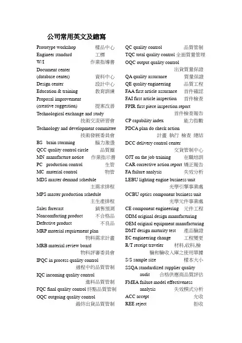
公司常用英文及縮寫Prototype workshop 樣品中心Engineer standard 工標W/I 作業指導書Document center(database center) 資料中心Design center 設計中心Education & training 教育訓練Proposal improvement(creative suggestion) 提案改善Technological exchange and study技術交流研習會Technology and development committee技術發展委員會BS brain storming 腦力激盪QCC quality control circle 品質圈MN manufacture notice 作業指示書PC production control 生管MC material control 物管MDS master demand schedule主需求排程MPS master production schedule主生產排程Sales forecast 銷售預測Noncomforting product 不合格品Defective product 不良品MRP material requirement plan物料需求計畫MRB material review board物料評審委員會IPQC in process quality control過程中的品質管制IQC incoming quality control進料品質管制FQC final quality control終點品質管制OQC outgoing quality control最終出貨品質管制QC quality control 品質管制TQC total quality control全面質量管理OQC output quality control出貨質量保證QA quality assurance 質量保證QE quality engineering 品質工程FAA first article assurance 首件確認FAI first article inspection 首件檢查FPIR first piece inspection report首件檢查報告CP capability index 能力指數PDCA plan do check action計畫執行檢查總結DCC delivery control center交貨管制中心OJT on the job training 在職培訓CAR corrective action report 矯正報告FA failure analysis 失效分析LEBU lighting engine business unit光學引擎事業處OCBU optics component business unit光學元件事業處CE component engineering 元件工程ODM original design manufacturing OEM original equipment manufacturing DMT design maturity test 產品驗證EC engineering change 工程變更R/T receipt traveler 材料,收料,檢驗和驗收入庫之使用單據S/S sample size 樣本大小SSQA standardized supplier qualityaudit 合格供應商品質評估FMEA failure model effectivenessanalysis 失效模式分析ACC accept 允收REE reject 拒收AQL acceptable quality level允收品質水準CR critical 極嚴重的MAJ major 主要的MIN minor 輕微的Q/R/S quality/reliability/service品質/可靠度/服務P/N part number 料號L/N lot number 批號AOD accept on deviation 特采UAI use as it 特采PPM percent per million 百萬分之一DIM dimension 尺寸DIA diameter 直徑N number 樣品數ZD zero defect 零缺陷QIT quality improvement team品質改善小組QI quality improvement 品質改善QP quality policy 質量方針TQM total quality management全面質量管理7QCTools 7 quality control tools品管七大手法RMA return material audit 退料認可ECR engineering change request工程變更申請ECN engineering change notice工程變更通知PCN process change notice制程改動通知PMP process management plan制程管制計畫SIP standard inspection procedure制造檢驗標準程序SOP standard operation procedure制造作業標準程序BOM bill of material 物料清單SPEC specification 規格PS package specification 包裝規格GS general specification 一般規格IS inspection specification成品檢驗規格ES engineering standard 工程標準ISO international standard organization國際標準化組織PMC production & material control生產和物料控制PCC product control center生產管制中心PPC production plan control生產計畫控制QE quality engineering 品質工程ME mechanical engineering 機構研發EE electronic engineering 電子研發OE optics engineering 光電研發MFG manufacturing 制造部PE product engineering 產品工程CS customer service 客服IE industrial engineering 工業工程RD research & design 設計開發(研發) PO purchasing order 採購訂單MO manufacture order 生產單SWR special work request特殊工作需求LRR lot reject rate 批退率ASAP as soon as possible 盡可能快的N/A not applicable 不適用NG not good 不行,不合格APP approve 認可,承認CHK check 確認ASS’Y assembly 裝配,組裝TBA to be assured 待定GP green product 綠色產品SQA strategy quality assurance策略品質保證DQA design quality assurance設計品質保證MQA manufacture quality assurance製造品質保證SSQA sales & service quality assurance銷售及服務品質保證QBR quarter business report季度商務報告B2C business to customerB2B business to businessGP green product 綠色產品TPM total production maintenance全面生產保養MRP material requirement planning物料需求計畫A VL approved vendor list供應商承認階段VQA vendor quality assurance供應商品保QVL qualified vendor list合格供應商名冊POP procedure of packaging 包裝程序EOL end of lifeHS hazardous substance 有害物質HSF hazardous substance free無有害物質Oracle 數據庫PES product engineering specification產品工程規格PMC product & material control資材單位W/I 作業指導書President 董事長Operator 作業員Position 職務GM general manager 總經理Special assistant 特助Vice manager 副理Vice supervisor 副課長Group leader 組長Line leader 線長Supervisor 課長Responsible department 負責單位Human resources department人力資源部Head count 人頭數Production unit 生產單位Meeting minutes 會議紀錄Distribution department 分發單位Planning department 企劃部Subject 主題Conclusion 結論Decision items 決議事項Pre-fixed finishing date 預定完成日Production capacity 生產力Cause analysis 原因分析Waste materials 廢料Description 品名Specification 規格Work order 工令Revision 版次Remark 備註Registration 登記Registration card 登記卡To control 管制Application form for purchase 請購單Consume, consumption 消耗To notify 通知To fill in 填寫To collect, to gather 收集Statistics 統計Cosmetic inspection standard外觀檢驗規範Raw material 原料Material 物料Material check list 物料檢查表Finished product 成品Semi-finished product 半成品Good product, accepted goods, Accepted parts, good parts 良品Defective product, non-good parts不良品Disposed goods 處理品Warehouse, hub 倉庫Flow chart 流程表單Production tempo 生產進度現狀Lots of production 生產批量Manufacture procedure 制程To revise, modify 修訂Delivery deadline 交貨期Equipment 設備Patent 專利Supply and demand 供求Career card 履歷卡Work cell, work shop 工作間Packaging 打包Assembly line 組裝線Layout 布置圖Packing 包裝Qualified products, up-to-grade products良品Defective products,Not up-to-grade products 不良品Poor processing 制程不良Poor incoming part 來件不良Excessive defect 過多的缺陷Critical defect 極嚴重缺陷Major defect 主要缺陷Minor defect 次要缺陷Not up to standard 不合規格WIPMRS marketing request specification市場規格需求表Master schedule 開發進度表Product engineering spec draft產品工程規格初稿BU head 事業處最高主管Project code 專案代號Project leader 專案負責人Check point 查檢點CPC 揚皓NRE no return expenses 不可回收花費NDA non disclosure agreement保密協議MTBF 驗證產品壽命ICT in-circuit testOSP outside processing 外包MOQ minimum order quantity最小訂單量MRP material request plan物料需求規劃ETD estimated time of departure估計出發時間ETA estimated time of arrival估計到達時間NPI new product introduction新產品引進–量產的第一批產品Rear cell 後群MTBF: Mean Time Between Failure帄均故障间隔时间FPY first pass yield 直通率引擎和系統常用專業名詞中英文對照表引擎產品物料BALLAST 電源高壓板C CONNECTOR C型插槽CABLE 連接線CARTON 外包裝紙箱COLOR WHEEL 色輪COLOR WHEEL BRACKE 色輪支架COLOR WHEEL RUBBER色輪橡膠墊片CUSHION 包裝泡棉CW MODULE COVER 色輪上蓋DB (DYNAMIC BLACK MODULE)暗場處理器DMD 數微晶片DMD COMPRESS COVER數微晶片固定壓板DMD RUBBER 數微晶片防塵片ENGINE BOTTOM HOUSING引擎下蓋ENGINE TOP HOUSING 引擎上蓋E-RING 卡環F/B SHELL BASE 下鐵蓋F/B SHIELDING COVER 上鐵蓋F/B(PCBA FORMATTER BOARD)訊號驅動板FAN 風扇HEAT SINK 散熱片INTERFACE PLATE 介面板LABEL 標籤LAMP 燈泡LAMP CHANGER 燈座LAMP COVER 燈罩LAMP HANDLER 燈把LAMP HOUSING MODULE 燈殼LENS1 透鏡1 LENS2 & 3 透鏡2&3 LENS4 透鏡4 L-SHAPE FIXED FOCUS LENSL型鏡頭MIRROR 鏡片MIRROR 1 PRESSOR 鏡片1壓板MIRROR 2 PRESSOR 鏡片2壓板PE BAG 防靜電包裝袋PHOTO SENSOR 光感應器ROD 積光柱ROD HOLDER 積光柱外殼RSP (REFLECTIVE SMOOTH PICTURE MODULE)反射式圖像帄滑處理模塊RUBBER BUNG 橡皮塞SCREW 螺絲SILICA GEL DESICCANT矽膠乾燥劑SILICON RUBBER 橡膠墊片SPONGE 海綿墊片SPRING 彈片TAPER SPRING 錐形彈簧THERMAL PAD 導熱片THERMAL SENSOR 溫度感應器THERMAL SWITCH 溫度開關TIR PRISM 稜鏡UV-IR 紫外/紅外線濾光鏡片引擎設備/工具PC-CHROMA 電腦訊號產生器CHROMA2327 訊號產生器2327 T-10 照度計(T-10) CL-200 色度計(CL-200) PRE-ASSEMBL Y STATION 前加工站ASSEMBLY STATION 組裝站PRE-ALIGNMET STATION 粗調整站ALIGNMET STATION几何失真/功能調整站BURN-IN ROOM 燒機室SHOOT MEASURE STATION光學參數測試站FQC 最終品質檢查站OQC 出貨品質檢查站ALIGNMET 几何失真/功能調整SHOOT MEASURE 光學參數測試引擎功能描述FOCUS 聚焦KEYSTONE 几何邊框COLOR BAND 色帶COLOR INDEX 色輪指數SP GAIN 圖像帄滑增益值FLARE 拖影CCA 白帄衡調整BAR CODE 條形碼PIXEL 像素CORE 像素中心亮斑LUX 亮度TIMING 時序PATTERN 畫面WHITE PATTERN 白畫面BLACK PATTERN 黑畫面R/G/B PATTERN 紅/綠/藍畫面CHECK BOARD PATTERN棋盤格畫面COLOR SMOOTH PICTURE PATTERN 色階畫面RASTER CROSSHATCH PATTERN十字中心畫面BLUE90 PATTERN 90色度藍畫面GRAY16 PATTERN 16色度灰畫面RESOLUTION PATTERN解析度畫面GHOST PATTERN 鬼影畫面LATERAL COLOR PATTERN色相差畫面系統SCM board (System control module)系統控制板CCPSU board (Constant Current Power Supply)恆定電流供應器DSP board (digital signal process)數位訊號處理板BIOS (basic input/output system)基本輸入輸出系統Thermal sensor board 溫度感應板HDD (hard disk)硬盤Motherboard 主機板IR(infrared) 紅外線CPU (central processing unit)中央處理器DRAM (Dynamic Random Access Memory)動態隨機存取記憶體(內存條) Calibration 校正Burn-in 燒機CD(Compact Disk) 光碟DVD (Digital Video / Versatile Disk)數位影音光碟機EC(Error Code) 錯誤代碼OS(Operation System) 操作系統PC(Personal Computer) 個人電腦UV(Ultraviolet) 紫外線LCD (Liquid Crystal Display)液晶顯示器CRT (Cathode Ray Tube)陰極射線管顯示器Ostar 紅外線發射裝置Camera 攝影機Card reader 讀卡器Video card 電腦顯示卡EEPROM (Electrically Erasable Programmable Read-Only Memory)電子式可抹唯讀記憶體Hi-pot 高壓測試電子LVPS (low voltage Power supply)低電壓電源供應器Ballast 鎮流器DVI TO LVDS BOARD數字轉低電壓差分訊號板HDMI (high definition multi media)高清度多媒體接口LVDS (low voltage differential signal)低電壓差分訊號DVI (digital visual interface)數字視頻接口DMD (Digital Micromirror Device)數字微鏡器件Adapter 電源適配器MCU Board (Micro controller unit)微控制單元板RSP Board (Reflective Smooth PictureTM )反射帄滑圖像板DB Board (Dynamic black)亮暗處理板I/O Board (Input/output)輸入輸出板M/B (main board)主板Photo sensor board 光感應板。
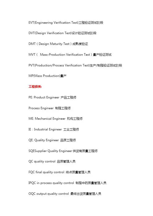
EVT(Engineering Verification Test)工程验证测试阶段DVT(Design Verification Test)设计验证测试阶段DMT(Design Maturity Test)成熟度验证MVT(Mass-Production Verification Test)量产验证测试PVT(Production/Process Verification Test)生产/制程验证测试阶段MP(Mass Production)量产工程师类:PE: Product Engineer 产品工程师Process Engineer 制程工程师ME: Mechanical Engineer 机构工程师IE:Industrial Engineer 工业工程师QE: Quality Engineer 品质工程师SQESupplier Quality Engineer供货商质量工程师QC quality control 品质管理人员FQC final quality control 终点质量管理人员IPQC in process quality control 制程中的质量管理人员OQC output quality control 最终出货质量管理人员IQC incoming quality control 进料质量管理人员TQC total quality control 全面质量管理POC passage quality control 段检人员QA quality assurance 质量保证人员OQA output quality assurance 出货质量保证人员QE quality engineering 品质工程人员TE Test Engineer 测试工程师AE Automatic Engineer 自动化工程师研发类:R&D Research & Design 设计开发部ID (Industry Design)工业设计MD (Mechanical Design)结构设计HW(Hardware) 硬件设计SW(Software)软件设计PDM Product Data Management 产品数据管理PLM product lifecycle management 产品生命周期管理电子设计:ICT In Circuit Test 电路测试PCB Printed Circuit Board 印刷电路板PCBA Printed Circuit Board Assembly 印刷电路板装配FPC FlexiblePrintedCircui 挠性电路板EMI Electrical Magnetic Interference 电子干扰RFI adio Frequency Interference射频干扰。
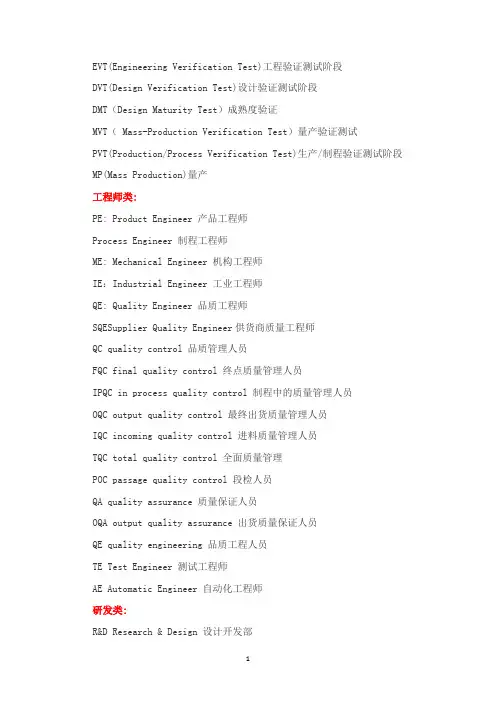
EVT(Engineering Verification Test)工程验证测试阶段DVT(Design Verification Test)设计验证测试阶段DMT(Design Maturity Test)成熟度验证MVT( Mass-Production Verification Test)量产验证测试PVT(Production/Process Verification Test)生产/制程验证测试阶段MP(Mass Production)量产工程师类:PE: Product Engineer 产品工程师Process Engineer 制程工程师ME: Mechanical Engineer 机构工程师IE:Industrial Engineer 工业工程师QE: Quality Engineer 品质工程师SQESupplier Quality Engineer供货商质量工程师QC quality control 品质管理人员FQC final quality control 终点质量管理人员IPQC in process quality control 制程中的质量管理人员OQC output quality control 最终出货质量管理人员IQC incoming quality control 进料质量管理人员TQC total quality control 全面质量管理POC passage quality control 段检人员QA quality assurance 质量保证人员OQA output quality assurance 出货质量保证人员QE quality engineering 品质工程人员TE Test Engineer 测试工程师AE Automatic Engineer 自动化工程师研发类:R&D Research & Design 设计开发部ID (Industry Design)工业设计MD (Mechanical Design)结构设计HW(Hardware) 硬件设计SW(Software)软件设计PDM Product Data Management 产品数据管理PLM product lifecycle management 产品生命周期管理电子设计:ICT In Circuit Test 电路测试PCB Printed Circuit Board 印刷电路板PCBA Printed Circuit Board Assembly 印刷电路板装配FPC FlexiblePrintedCircui 挠性电路板EMI Electrical Magnetic Interference 电子干扰RFI adio Frequency Interference射频干扰。
3. 启动和状态管理3.1. TPM-InitTPM-Init是一种初始化TPM的物理方法。
在可信计算平台内部,当一则平台消息被发送到TPM时,无TPM-Init序数。
在PC机中这个命令通过LPC总线连接到TPM,告知TPM 平台正在运行启动程序。
TPM-Init使TPM处于等待TPM-Startup命令的状态。
3.2. TPM-StartupTPM-Init之后执行TPM-Startup命令,该命令是TPM初始化所需的物理声明。
在可信计算平台中经常有许多请求需要重启,在TPM上对这些请求的响应需要进行不同的操作。
重启声明不包含足够的信息去通知TPM需要哪种类型的重启。
平台初始化代码将已知的额外信息传送至TPM。
TPM-Startup命令提供发送信息机制。
TPM有三种不同的启动方式:(1)“清除”启动:所有变量被设为默认值或者稳定状态。
(2)“保存”启动:TPM在原来TPM-SaveState的基础上恢复一些信息和各种取值,这种恢复的前提是TPM-Init运行成功。
如果“保存”启动失败,则必须先关闭TPM。
CRTM不能使TPM处于此种状态,即不可信的上层软件层发布“清除”操作,然后扩充PCR的状态,以防CRTM冒充。
(3)“无效”启动:TPM自动关闭,在TPM处于完全运行状态之前要求再次执行TPM-Init命令。
3.3. TPM-SaveState这个命令用于提示TPM保存某个状态信息。
如果与之相关的隐藏存储是非易失的,则表示TPM-SaveState命令无效。
如果与之相关的隐藏存储是易失的,而且TPM本身不能及时发现外部掉电从而转移数据到非易失存储器的话,在TPM进入低电平或无电状态之前,应执行TPM-SaveState命令。
4测试管理4. 1 TPM-SelfTestFullTPM-SelfTestFull命令测试TPM的所有性能。
与TPM-ContinueSelfTest不同,TPM-ContinueSelfTest也许在任意时刻立即返回,然后再继续测试,而TPM-SelfTestFul总是不断地执行测试,然后返回成功或失败。
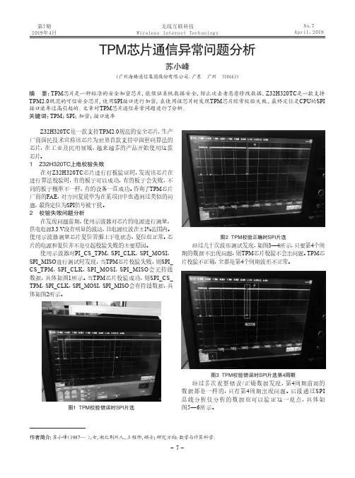
第7期2019年4月No.7April,2019Z32H320TC是一款支持TPM2.0规范的安全芯片,生产厂商国民技术宣称该芯片为世界首款支持中国密码算法的芯片,在工业及民用领域,越来越多的产品开始使用这款芯片。
1 Z32H320TC上电校验失败在对Z32H320TC芯片进行打板验证时,发现该芯片在进行算法校验时,有的板子可以成功,有的板子会失败,不同的板子概率不一样,有的设备一直成功。
咨询了TPM芯片厂商的FAE,对方回复说华为在某项目中也遇到过类似的问题,最终定位为SPI信号被干扰。
2 校验失败问题分析在发现问题前期,使用示波器对芯片的电源进行测量,供电电源3.3 V没有明显的波动,且电源纹波在±1%范围内。
使用示波器测量芯片复位管脚上下电状态,复位也正常。
芯片的电源和复位并不是引起校验失败的主要原因。
使用示波器对PI_CS_TPM,SPI_CLK,SPI_MOSI,SPI_MISO进行测试时发现,当TPM芯片校验失败,则SPI_CS_TPM,SPI_CLK,SPI_MOSI,SPI_MISO会无持续数据,具体如图1所示。
当TPM芯片校验成功,则SPI_CS_TPM,SPI_CLK,SPI_MOSI,SPI_MISO会有持续数据,具体如图2所示。
图1 TPM校验错误时SPI片选图2 TPM校验正确时SPI片选经过几十次波形测试发现,如图3—4所示,只要第4个周期的数据不出现问题,则TPM芯片校验不会出问题。
TPM芯片校验不正确,全都是第4个周期波形不正常。
图3 TPM校验错误时SPI片选第4周期经过多次观察错误/正确数据发现,第4周期前面的数据都是一样的,只有第4周期出现问题。
后续通过SPI总线分析仪分析的数据也可以验证这一观点,具体如图5—6所示。
作者简介:苏小峰(1987—),女,湖北荆州人,工程师,硕士;研究方向:数学与计算科学。
摘 要:TPM芯片是一种标准的安全加密芯片,能保证系统数据安全,防止攻击者恶意修改数据,Z32H320TC是一款支持TPM2.0规范的可信安全芯片,使用SPI接口进行加密,在使用该芯片时发现TPM芯片经常校验失败,最终定位是CPU的SPI 接口速率过高引起的。
ISO 国际标准化组织(ISO,International Organization for Stan-dardization缩写)。
OEM是英文Original Equipment Manufacturer的缩写,意思是原设备制造商R&D (research&design) 研发ODM,即Original design manufacture(原始设计商)的缩写。
IQC incoming quality controlRD research development centerIPQC in process quality controlRD HQ research development center head quarterFQC final quality controlQA quality assuranceBOM bill of materialPVT product verification test产品验证测试OQC outgoing quality controlPRP phase review process阶段检讨过程QE quality engineeringPM project managementDCC document center controlPJE project engineerECN engineering change noticePE product engineerECR engineering change requestNPI new product introductionMRB material review bomMP mass productionCAR corrective action request纠正行动请求MFG manufacturingFPC flexible printed circuit boardME mechanical engineerNCR non conforming reportKBD keyboardOBE out of box evaluationIFR instant failure rateIQA internal quality audit内部质量审核IFIR instant failure incident rate即时故障发生率PCR process change requestHW hardwareIPO internal purchase officeN/A No ActionIE industrial engineeringESD electrostatic discharge静电放电QPA quality process audit EOL end of lifeQSA quality system auditEN engineering noticeATE automatic test equipment自动测试设备EMI electromagnetic interference电磁干扰AOI automatic optical inspection自动光学检测EMC electromagnetic compatibility电磁兼容性PCBA print circuit board assembly印刷电路板组装EE electronic engineer(ing)TTL technology transfer listEDC electronic data centerSQA supplier quality assuranceECO engineering change orderORT ongoing reliability testing(可靠性测试)DVT design verification test(设计验证测试)QM quality manualDOA dead on arrivalSW softwareCAD/ID computer aided design /industrial designSOW standard of workBIOS basic input /output systemSCSI small computer system interface AP application programSA software applicationAFR annual failure rateSO sales orderNTF no trouble foundMRP material requirement planningCND can not duplicateAVL approved vendor listDPPM defect parts per millionFAI first article inspectionFMEA failure mode effect analysisCLCA closed loop corrective actionLRR line reject rate measured by DPPM MQR monthly quality reviewMTQ manufacturing ,test and quality RCA root cause analysisPFMEA process failure mode effect analysisSFIS Shop Floor Information System QEM Quality engineering measurement BGA Ball Grid ArrayIC Integrated CircuitQFP Quad Flat PackEOS Elwctrical Over StressTNB terminal notebook businessSMT Surface Mount Technology品质人员名称类QC quality control 品质管理人员FQC final quality control 终点品质管制人员IPQC in process quality control 制程中的品质管制人员OQC output quality control 最终出货品质管制人员IQC incoming quality control 进料品质管制人员TQC total quality control 全面质量管理POC passage quality control 段检人员QA quality assurance 质量保证人员OQA output quality assurance 出货质量保证人员QE quality engineering 品质工程人员品质保证类FAI first article inspection 新品首件检查FAA first article assurance 首件确认CP capability index 能力指数CPK capability process index 制程能力参数SSQA standardized supplier quality audit 合格供应商品质评估FMEA failure model effectiveness analysis 失效模式分析FQC运作类AQLAcceptable Quality Level 运作类允收品质水准S/S Sample size 抽样检验样本大小ACC Accept 允收REE Reject 拒收CR Critical 极严重的MAJ Major 主要的MIN Minor 轻微的Q/R/S Quality/Reliability/Service品质/可靠度/服务P/N Part Number 料号L/N Lot Number 批号AOD Accept On Deviation 特采UAI Use As It 特采FPIR First Piece Inspection Report首件检查报告PPM Percent Per Million 百万分之一制程统计品管专类SPC Statistical Process Control 统计制程管制SQC Statistical Quality Control 统计品质管制GRR Gauge Reproductiveness & Repeatability量具之再制性及重测性判断量可靠与否DIM Dimension 尺寸DIA Diameter 直径N Number 样品数其它品质术语类QIT Quality Improvement Team 品质改善小组ZD Zero Defect 零缺点QI Quality Improvement 品质改善QP Quality Policy 目标方针TQM Total Quality Management 全面品质管理RMA Return Material Audit 退料认可7QCTools 7 Quality Control Tools 品管七大手法ECN Engineering Change Notice工程变更通知(供应商)ECO Engineering Change Order工程改动要求(客户)PCN Process Change Notice 工序改动通知PMP Product Management Plan生产管制计划SIP Standard Inspection Procedure制程检验标准程序SOP Standard Operation Procedure 制造作业规范IS Inspection Specification 成品检验规范BOM Bill Of Material 物料清单PS Package Specification 包装规范SPEC Specification 规格DWG Drawing 图面系统文件类ES Engineering Standard 工程标准CGOO China General IWS International Workman Standard 工艺标准ISO International Standard Organization国际标准化组织GS General Specification 一般规格部类PMC Production & Material Control生产和物料控制PCC Product control center生产管制中心PPC Production Plan Control生产计划控制MC Material Control 物料控制DC Document Center 资料中心QE Quality Engineering 品质工程(部) QA Quality Assurance 品质保证(处) QC Quality Control 品质管制(课) PD Product Department 生产部LAB Laboratory 实验室IE Industrial Engineering 工业工程R&D Research & Design 设计开发部生产类PCs Pieces 个(根,块等)PRS Pairs 双(对等)CTN Carton 卡通箱PAL Pallet/skid 栈板PO Purchasing Order 采购订单MO Manufacture Order 生产单D/C Date Code 生产日期码ID/C Identification Code (供应商)识别码SWR Special Work Request 特殊工作需求L/N Lot Number 批号P/N Part Number 料号OEM Original Equipment Manufacture原设备制造PC Personal Computer 个人电脑CPU Central Processing Unit 中央处理器A.S.A.P As Soon As Possible 尽可能快的E-MAIL Electrical-Mail 电子邮件N/A Not Applicable 不适用QTY Quantity 数量I/O input/output 输入/输出NG Not Good 不行,不合格C=0 Critical=0 极严重不允许APP Approve 核准,认可,承认CHK Check 确认ASS'Y Assembly 装配,组装T/P True Position 真位度5WIH When, Where, Who, What, Why, How to6M Man, Machine, Material, Method, Measurement, Message4MTH Man, Material, Money, Method, Time, How 人力,物力,财务,技术,时间(资源)SQA Strategy Quality Assurance 策略品质保证DQA Design Quality Assurance设计品质保证MQA Manufacture Quality Assurance制造品质保证SSQA Sales and service Quality Assurance 销售及服务品质保证LRR Lot Reject Rate 批退率SPS Switching power supply 电源箱DT Desk Top 卧式(机箱)MT Mini-Tower 立式(机箱)DVD Digital Video DiskVCD Video Compact DiskLCD Liquid Crystal DisplayCAD Computer Aided DesignCAM Computer Aided ManufacturingCAE Computer Aided EngineeringPCB Printed Circuit Board 印刷电路板CAR Correction Action Report 改善报告NG Not Good 不良WDR Weekly Delivery Requirement 周出货要求PPM Percent Per Million 百万分之一TPM Total Production Maintenance全面生产保养MRP Material Requirement Planning物料需计划OS Operation System 作业系统TBA To Be Assured 待定,定缺。
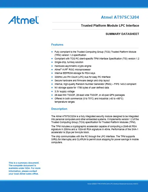
This is a summary document. The complete document is available under NDA. For more information, please contact your local Atmel sales office. Features●Fully compliant to the Trusted Computing Group (TCG) Trusted Platform Module(TPM) version 1.2 specification●Compliant with TCG PC client-specific TPM Interface Specification (TIS) version 1.2●Single-chip, turnkey solution●Hardware asymmetric crypto engine●Atmel® AVR® RISC microprocessor●Internal EEPROM storage for RSA keys●33MHz Low Pin Count (LPC) bus for easy PC interface●Secure hardware and firmware design and chip layout●Internal, high-quality Random Number Generator (RNG) – FIPS 140-2 compliant●NV storage space for 1756 bytes of user defined data● 3.3V supply voltage●28-lead thin TSSOP, 28-lead wide TSSOP, or 40-pad QFN packages●Offered in both commercial (0 to 70°C) and industrial (-40 to +85°C)temperature rangesDescriptionThe Atmel AT97SC3204 is a fully integrated security module designed to be integrated into personal computers and other embedded systems. It implements version 1.2 of the Trusted Computing Group (TCG) specification for Trusted Platform Modules (TPM).The TPM includes a cryptographic accelerator capable of computing a 2048-bit RSA signature in 200ms and a 1024-bit RSA signature in 40ms. Performance of the SHA-1 accelerator is 20μs per 64-byte block.The chip communicates with the PC through the LPC interface. The TPM supports SIRQ (for interrupts) and CLKRUN to permit clock stopping for power savings in mobile computers.Atmel AT97SC3204Trusted Platform Module LPC InterfaceSUMMARY DATASHEET1.Pin Configurations and PinoutsTable 1-1.Pin ConfigurationsTable 1-2.Pinouts2.Block DiagramThe TPM includes a hardware random number generator, including a FIPS-approved Pseudo Random NumberGenerator that is used for key generation and TCG protocol functions. The RNG is also available to the system togenerate random numbers that may be needed during normal operation.The chip uses a dynamic internal memory management scheme to store multiple RSA keys. Other than the standard TCG commands (TPM_FlushSpecific, TPM_Loadkey2), no system intervention is required to manage this internal key cache.The TPM is offered to OEM and ODM manufacturers as a turnkey solution, including the firmware integrated on the chip.In addition, Atmel provides the necessary device driver software for integration into certain operating systems, along with BIOS drivers. Atmel will also provide manufacturing support software for use by OEMs and ODMs during initialization and verification of the TPM during board assembly.Full documentation for TCG primitives can be found in the TCG TPM Main Specification, Parts 1 to 3, on the TCG Web site located at https://. TPM features specific to PC Client platforms are specified in the “TCG PC Client Specific TPM Interface Specification, Version 1.2”, also available on the TCG web site. Implementation guidance for 32-bit PC platforms is outlined in the “TCG PC Client Specific Implementation Specification for Conventional BIOS for TCG Version 1.2”, also available on the TCG website.3.Ordering InformationNote: 1.Please see the AT97SC3204 datasheet addendum for the complete catalog number ordering code.4.Package Drawings4.128X1 — 28-lead Thin TSSOP4.240ML1 — 40-pad VQFN5.Revision HistoryAtmel Corporation1600 Technology Drive, San Jose, CA 95110 USA T: (+1)(408) 441.0311F: (+1)(408) 436.4200| © 2013 Atmel Corporation. All rights reserved. / Rev.: Atmel-5295ES-TPM-AT97SC3204-LPC-Interface-Datasheet-Summary-032013Atmel®, Atmel logo and combinations thereof, Enabling Unlimited Possibilities®, AVR®, and others are registered trademarks or trademarks of Atmel Corporation or its subsidiaries. Other terms and product names may be trademarks of others.Disclaimer: The information in this document is provided in connection with Atmel products. No license, express or implied, by estoppel or otherwise, to any intellectual property right is granted by this document or in connection with the sale of Atmel products. EXCEPT AS SET FORTH IN THE ATMEL TERMS AND CONDITIONS OF SALES LOCATED ON THE ATMEL WEBSITE, ATMEL ASSUMES NO LIABILITY WHATSOEVER AND DISCLAIMS ANY EXPRESS, IMPLIED OR STATUTORY WARRANTY RELATING TO ITS PRODUCTS INCLUDING, BUT NOT LIMITED TO, THE IMPLIED WARRANTY OF MERCHANTABILITY, FITNESS FOR A PARTICULAR PURPOSE, OR NON-INFRINGEMENT. IN NO EVENT SHALL ATMEL BE LIABLE FOR ANY DIRECT, INDIRECT, CONSEQUENTIAL, PUNITIVE, SPECIAL OR INCIDENTAL DAMAGES (INCLUDING, WITHOUT LIMITATION, DAMAGES FOR LOSS AND PROFITS, BUSINESS INTERRUPTION, OR LOSS OF INFORMATION) ARISING OUT OF THE USE OR INABILITY TO USE THIS DOCUMENT, EVEN IF ATMEL HAS BEEN ADVISED OF THE POSSIBILITY OF SUCH DAMAGES. Atmel makes no representations or warranties with respect to the accuracy or completeness of the contents of this document and reserves the right to make changes to specifications and products descriptions at any time without notice. Atmel does not make any commitment to update the information contained herein. Unless specifically provided otherwise, Atmel products are not suitable for, and shall not be used in, automotive applications. Atmel products are not intended, authorized, or warranted。

EVT(Engineering Verification Test)工程验证测试阶段DVT(Design Verification Test)设计验证测试阶段DMT(Design Maturity Test)成熟度验证MVT(Mass-Production Verification Test)量产验证测试PVT(Production/Process Verification Test)生产/制程验证测试阶段MP(Mass Production)量产工程师类:PE: Product Engineer 产品工程师Process Engineer 制程工程师ME: Mechanical Engineer 机构工程师IE:Industrial Engineer 工业工程师QE: Quality Engineer 品质工程师SQESupplier Quality Engineer供货商质量工程师QC quality control 品质管理人员FQC final quality control 终点质量管理人员IPQC in process quality control 制程中的质量管理人员OQC output quality control 最终出货质量管理人员IQC incoming quality control 进料质量管理人员TQC total quality control 全面质量管理POC passage quality control 段检人员QA quality assurance 质量保证人员OQA output quality assurance 出货质量保证人员QE quality engineering 品质工程人员TE Test Engineer 测试工程师AE Automatic Engineer 自动化工程师研发类:R&D Research & Design 设计开发部ID (Industry Design)工业设计MD (Mechanical Design)结构设计HW(Hardware) 硬件设计SW(Software)软件设计PDM Product Data Management 产品数据管理PLM product lifecycle management 产品生命周期管理电子设计:ICT In Circuit Test 电路测试PCB Printed Circuit Board 印刷电路板PCBA Printed Circuit Board Assembly 印刷电路板装配FPC FlexiblePrintedCircui 挠性电路板EMI Electrical Magnetic Interference 电子干扰RFI adio Frequency Interference射频干扰。
编号:LMS/STD.15(1.0版本)如何编写STS/TIS1.定义STS:标准作业单(Standard Task Sheet),记录整个工作内容,它包含组员所要完成的所有工作。
设定组员有完成这些工作内容所需要具备的基本知识。
TIS:作业指导书(Standard Instruction Sheet),将工作任务分解成特定的步骤并记录,任务分解足够详细以保证工作能够成功实施。
(细分要求取决于员工知识要求)2.目的STS:让员工知道在非周期性工作下每天/周/月所要完成的工作内容;定义任务时间:例如,有些工作需要跨几个工作日才能完成。
TIS:为新员工提供工作指导;提供任务的文本历程;为审计、问题解决和持续改进提供基础。
3.STS/TIS样式3◇特别零件, PPE,在当周时间内,不定时对工段所有区域内的安全问题进行区域危险危害因素的随时识别、区域内的安全管理区域内不安全现象的整改状况、安全标识的有效状态、员工的设备安将不达标的具体问题在《问题对策表》上记录,制定行动计划措施,完成时间,将问题分解到责任人,对问题进行适及时交叉反及时交叉反图3-1图3-2在当周计划的时间内,参照《工段长分层审计》的内容,图4-1图4-2修改时间签名更改描述4.STS/TIS编写说明4.1 STS编写说明1、表头区2、工作要素区说明:1、频次:次数/(D(day)=每日、W(week)=每周、M(month)=每月、Y(year)=每年);2、公式:周期时间:(权衡值)=每项工作要素的每日用时之和;每项工作要素的每日用时=此项工作要素时间×工作频次。
表格公式为:=IF(O13="D",M13*N13,IF(O13="W",M13*(N13/5),IF(O13="M",M13*(N13/22),IF(O13="Y" ,M13*(N13/(22*12))))))其中,M13为完成工作要素的时间单元格,N13为完成工作要素的频次的次数单元格,O13为完成工作要素的频次的类型单元格,“5”为每周工作天数,“22”为每月工作天数,“12”为每年工作月数。
General Motors Customer Specific Requirements - ISO/TS16949 1. ScopeISO/TS 16949:2002, Second Edition, March 1, 2002, “Quality management systems – Particular requirements for the application of ISO 9001:2000 for automotive production and relevant service part organizations,” and this document define General Motors fundamental quality system requirements for organizations where automotive customer-specified parts, for production and/or service are manufactured. To satisfy supplier quality system requirements, General Motors will accept, as optional to QS-9000, a third party certification to ISO/TS 16949 that meets the following conditions:• The certification scope must include both ISO/TS 16949 and the accompanying ISO/TS 16949 GM-Customer Specific Requirements,• The certification must be conducted in compliance with the IATF recognized automotive certification scheme by a certification body contracted and recognized by an IATFOversight office.NOTE: The Quality System Requirements, QS-9000, 3rd Edition (QS-9000:1998),expires on December 14, 2006.All ISO/TS 16949:2002 requirements and the requirements of this document shall be addressed in the organization’s quality management system.2. References2.1 DaimlerChrysler, Ford Motor, General Motors Quality System Requirements (QS-9000), Third Edition, March, 1998.2.2 DaimlerChrysler, Ford Motor, General Motors Production Part Approval ProcessPPAP), Third Edition, September, 1999.2.3 DaimlerChrysler, Ford Motor, General Motors Statistical Process Control (SPC),FirstEdition, 1992.2.4 DaimlerChrysler, Ford Motor, General Motors Advanced Product Quality Planning andControl Plan, June, 1994.2.5 DaimlerChrysler, Ford Motor, General Motors Measurement Systems Analysis, MSAThird Edition, March, 2002.2.6 DaimlerChrysler, Ford Motor, General Motors Potential Failure Mode and EffectsAnalysis, FMEA Third Edition, July 2001.2.7 IAF Guidance on the Application of ISO/IEC Guide 62:1996, December, 2001.2.8 IATF Guidance to ISO/TS 16949:2002, AIAG Edition, 2002.2.9 Automotivecertification scheme for ISO/TS 16949:2002, Rules for Achieving IATF Recognition, First Edition for ISO/TS 16949:2002, March, 2002.2.10 ISO/TS 16949:2002, 1st Edition, March 20022.11 ISO/TS 16949:1999, First Edition (2nd Printing), March, 1999.The latest edition of the reference documents listed applies unless otherwise specified by the GM Procuring Division. Copies of QS-9000, PPAP, APQP, FMEA, MSA, SPC, IATF Guidance, ISO/TS 16949 “Rules”, ISO/TS 16949 Checklist, ISO/TS 16949:1999, and other related manuals are available from AIAG at 1-248-358-3003. Copies of ISO documents are available from the American National Standards Institute (ANSI) at (212) 642-4980.The above references listed as requirements are described in section 4 of this document.3. DefinitionsWhere inconsistent terminology exists between ISO/TS 16949:2002 and this document, this document shall take precedence. Otherwise the definitions from ISO/TS 16949:2002 apply to this document.3.1 Accredited LaboratoryAccredited Laboratory is one that has been reviewed and approved by a nationally-recognized accreditation body, or as an alternative a customer recognized accreditation body, conforming to ISO/IEC Guide 58 for calibration or test laboratory accreditation to ISO/IEC Guide 17025, or national equivalent.NOTE: The above definition also applies to the QS-9000 reference manuals currently in effect.Part3.2 ActiveAn active part is one currently being supplied to the customer for original equipment or service applications. The part remains active until tooling scrap authorization is given by the appropriate customer activity. For parts with no customer-owned tooling or situations where multiple parts are made from the same tool, written confirmation from the customer Purchasing activity is required to deactivate a part.NOTE: For bulk material, “active part” refers to the bulk material contracted, not the parts that are subsequently produced from that material.Parts3.3 AftermarketReplacement parts not procured or released by OEM for service part applications which may or may not be produced to original equipment specifications.3.4 ConsultingFor the purposes of TS16949:2002, consulting is the provision of training, documentation development, or assistance with implementation of quality systems to a specific customer. If these activities are open to the public, advertised, and not customer specific, they are considered training rather than consulting. Other products, processes or services may be offered directly or indirectly, provided they do not compromise confidentiality or the objectivity or impartiality of its certification process or decisions (refer to IAF Guidance on the Application of ISO/IEC Guide 62, Issue 2, dated December, 2001.)]3.5 CustomerReferences to “customer” in ISO/TS 16949:2002 and this document shall be interpreted as the Procuring Division of General Motors for suppliers pursuing third party registration to ISO/TS 16949:2002 to satisfy General Motors sourcing requirements third party quality system assessment registration.3.6 ErgonomicsErgonomics is the evaluation of the design of a product or process to assure compatibility with the capabilities of human beings. Analysis of motion refers to capabilities of people with respect to tasks (e.g. lifting, twisting, reaching) to prevent or relieve problems of strain, stress, excessive fatigue, etc. Factors involved include anatomical dimensions of the worker, placement of products to be worked upon, placement of buttons/switches, physical loads imposed on the worker, and environmental effects such as noise, vibration, lighting and space.3.7 Initial Process StudyInitial Process Studies are short-term studies conducted to obtain early information on the performance of new or revised processes relative to internal or customer requirements. In many cases, preliminary studies should be conducted at several points in the evolution of new processes (e.g. at the equipment or tooling subcontractor’s plant, after installation at the supplier’s plant). These studies should be based on as many measures as possible. When utilizing X-Bar and R charts, at least twenty-five subgroups (minimum of four pieces per sub-group) are required to obtain sufficient data for decision-making. When this amount of data isnot available, control charts should be started with whatever data is available. See Production Part Approval Process manual.3.8 PPMPPM (parts per million) is a method of stating the performance of a process in terms of actual nonconforming material. PPM data can be used to prioritize corrective actions. Definition of defective units varies with customer (e.g. all sorted, only those found to be wrong, all in box). (Reference GP-5 Supplier Quality Processes and Measurements Procedure, GM1746 for additional PPM definition.)Indices3.9 QualitySee DaimlerChrysler, Ford, General Motors Statistical Process Control reference manual.3.10 OrganizationOrganizations are defined as providers of: a) production materials, b) production or service parts, or c) heat treating, plating, painting or other finishing services, directly to General Motors or other customers subscribing to this document.NOTE: In QS-9000, these providers are typically referred to as suppliers toDaimlerChrysler, Ford and General Motors however for the purpose of this documentthey are defined as the “organization” or “supply organization.” ISO/TS 16949:2002 (See also Section 3 Terms and definitions.)3.11 Service partsReplacement parts manufactured to OEM specifications, which are procured or released by the OEM for service part application.3.12SuppliersSuppliers (previously called subcontractors in QS-9000)are defined as providers of production materials, or production or service parts, directly to an organization provider of General Motors or other customers subscribing to this document. Also included are providers of heat-treating, painting, plating or other finishing services.3.13 Value-Added Production ProcessesActivities or operations for which a customer would be willing to pay, if given the option.See also ISO/TS 16949:2002, Second Edition (March, 2002), definition of “manufacturing” 3.1.6, “site” 3.1.11, and “remote location” 3.1.10.4. Requirements4.1 ISO TS 16949:2002 (Second Edition), March, 2002- Related RequirementsAll references to clauses in this section pertain to ISO/TS 16949:2002, unless otherwise stated. 4.1.1 Tooling ManagementThe requirements for tooling management (7.5.1.5) may not be applicable to warehouses or distributors as remote sites.4.1.2 Records RetentionProduction part approvals, tooling records, APQP records, purchase orders and amendments shall be maintained for the length of time that the part (or family of parts) is active (see Definitions 3.1) for production and service requirements plus one calendar year unless otherwise specified by the customer.NOTE: All customer purchase orders/amendments are included in this requirement.Organization purchase orders/amendments for customer-owned tooling are included in this requirement.Quality performance records (e.g. control charts, inspection and test results) shall be retained for one calendar year after the year in which they were created.Records of internal quality system audits and management review shall be retained for three years.Retention periods longer than those specified above may be specified by an organization in their procedures. The organization shall eventually dispose of records.These requirements do not supersede any regulatory requirements. All specified retention periods shall be considered “minimums”.4.1.3 Electronic CommunicationReference cl. 7.2.3.1NOTE: Examples of such systems for suppliers to GM’s North American Operations are:1) requirement planning information such as the Electronic Data Interchange (EDI) ANSIASC X12 830 transaction set or the EDIFACT DELFOR message, and 2) shippingschedules such as the ANSI ASC X12 862 or 866 transaction sets or the EDIFACTDELJIT message.4.1.4 Shipment Notification SystemReference cl. 7.2.3.1NOTE: Examples of such systems for suppliers to GM’s North American Operations are:1) the ANSI ASC X12 856 transaction set, or 2) the EDIFACT DESADV message. ForEDI assistance, contact 01-810-947-5566. For EDIFACT assistance, and confirmationof the required implementation date for a supplier, contact 01-248-265-9907.4.1.5 Special CharacteristicsThe supplier shall use General Motors Key Characteristic Designation System definitions and symbols to comply with ISO/TS 16949:2002 special characteristics requirements (e.g. cl.7.2.1.1), and as provided in 4.2.2, General Procedures and Other Requirements, and 4.2.2.11, Key Characteristic Designation System (KCDS), (GM 1805 QN) which defines GM’s approach to “special” characteristics.4.1.6 Design ChangesAll design changes, including those proposed by suppliers, shall have written customer approval, or waiver of such approval, prior to production implementation. See cl. 7.3.7 and 7.1.4. See also the Production Part Approval Process manual.For proprietary designs, impact on form, fit, function, performance, and/or durability shall be determined with the customer so that all effects can be properly evaluated.4.1.7 Official Language VersionThe English language version of ISO/TS 16949:2002 or QS-9000, 3rd Edition and related reference documents shall be the official version for purposes of third party registration. Sanctioned translations shall:• be for reference only,• reference the English language as the official version,• not contain ISO 9001:2000 text verbatim, and• include General Motors in the copyright statement.Any other language translations are not authorized.4.1.8 Part Approval ProcessThe supplier shall comply with the Chrysler, Ford, GM Production Part Approval Process (PPAP) manual to comply with cl. 7.3.6.31. PPAP-Vehicle Assembly Centers (Assembly Plants)Unless otherwise specified by the Customer, PPAP requirements for vehicle assemblycenters shall be taken from a specified production run of saleable pilot vehicles.4.1.9 Customer SatisfactionTrends in quality system performance and customer satisfaction (see Cl. 5.2, 5.6.1.1, 7.4.3.2, and 8.2.1.1) should be compared to those of competitors, or appropriate benchmarks, and reviewed by top management.4.1.10 Internal Auditor QualificationsInternal auditors should be qualified as recommended in ISO 19011, 1st Edition – Sections7.1-7.5, for Quality Management Systems application. In addition internal auditors should be competent in understanding and applying the Process Approach of Auditing (See “Process Approach”, Section 0.2 of ISO/TS 16949:2002), Core Tools (e.g. reference manuals including PPAP, APQP, MSA, SPC, and FMEA) as applicable, and GM Customer Specifics, as applicable.NOTE: A process and plan with implementation monitoring to assure qualified internal auditors is evidence of compliance.4.1.11 Supplier Quality Management System Development (cl. 7.4.1.2)Note: This supplier development clause, cl. 4.1.2, applies to suppliers of the organization who are providers of production materials, or production or service parts, directly to a supplier to Chrysler, Ford, General Motors or other customers subscribing to this document. Also included are providers of heat-treating, painting, plating or other finishing services.Indirect and service providers are not included in this requirement, e.g. distributors adding no manufacturing value, logistics, sequencers, parts packagers, tooling & equipment.Note: The use of customer-designated suppliers to the organization (subcontractors) does not relieve the supplier of the responsibility for ensuring the quality of subcontracted parts, materials and services.4.1.11.1 Customer acceptance of QS-9000:1998Registration to QS-9000:1998, (QS-9000, 3rd Edition) shall be accepted as an alternative to registration to ISO 9001:2000.4.1.11.2 Customer acceptance of 2nd Party Audits and Criteria for Approval General Motors Corporation will recognize 2nd Party audits as compliance to ISO/TS 16949:2002, Clause 7.4.1.2 and as an alternative to ISO 9001:2000 certification. The statement of authorization below provides the requirements and conditions for GM approval.A supply organization that utilizes 2nd party assessment to comply with clause 7.4.1.2 is required by General Motors to utilize second party assessors who satisfy all elements of the criteria specified as “GM approved 2nd Party requirements” stated below.GM-approved 2nd Party requirements:1. The supply organization (2nd Party) must be ISO/TS 16949 certified and registered bythe IATF.2. The supply organization (2nd Party) cannot be on ISO/TS 16949 probation or suspension.3. The supply organization (2nd Party) must utilize a qualified ISO Lead Auditor, or aqualified Internal Auditor with evidence of their successful completion of training, such as AIAG "Internal Auditing for ISO/TS 16949," or evidence of a minimum of five internal ISO/TS 16949 audits under the supervision of a qualified Lead Auditor.4. The supply organization (2nd Party) must audit annually each qualifying subcontractor for whom it has performed a 2nd Party assessment, and maintain records of these audits.5. The duration of these audits must conform to the full application of the Audit Day Requirements table of the current edition of “Automotive Certification Scheme for ISO/TS 16949:2002, Rules for achieving IATF recognition”.6. Any of the IATF recognized and currently approved auditors may perform such audits when contracted by the supply organization.4.1.11.3 Supplier Development of Specially Designated Small Suppliers When a supplier (subcontractor) to an organization is so small as to not have adequate resources to develop a system according to ISO/TS 16949:2002 or ISO 9001:2000 certain specified elements may be waived by the organization of their supplier. The organization shall have decision criteria in writing, approved by the customer and applied consistently to determine the specially designated suppliers for which this provision may apply.Note: ISO 9001:2000 and ISO/TS 16949:2002 contain fundamental quality system requirements of value to any size of provider of production/ service parts/ materials. There are a number of methods to implement a compliant system, so it is recognized that a simpler Quality Management System approach could be used for the smaller suppliers of organizations to which ISO/TS 16949, clause 7.4.1.2 applies.4.2 General Motors - Specific Requirements4.2.1 Third-Party Registration RequirementsProduction and Service Part Suppliers to General Motors, including GM Holdens, shall be third-party registered to ISO/TS 16949:2002, including the requirements in this document, by an IATF-recognized certification body using the current edition in effect of the automotive registration scheme, “Automotive Certification Scheme for ISO/TS 16949:2002, Rules for achieving IATF recognition.” In the alternative, supply organizations for which certification applies, may satisfy General Motors third party registration requirements by obtaining certification to ISO/TS 16949:1999 by an IATF recognized certification body in accordance with the appropriate and current “Rules” for certification until December 15, 2003, or to QS-9000:1998 by an automotive registration scheme recognized by General Motors until December 14, 2006. Such certification shall include the requirements in this document, or in the case of QS-9000:1998, the General Motors-Specific Requirements.NOTE 1: Supply organizations to General Motors certified to ISO/TS 16949:1999 may upgrade certification to ISO/TS 16949:2002 for the period of up to one year after 15 December 2003, consistent with the surveillance cycle.NOTE 2: Supply organizations to General Motors who fit the applicability requirements of ISO/TS 16949:2002 and are not certified to ISO/TS 16949:2002 by 14 December 2006, at a minimum, are subject to New Business Hold – Quality status. See also 4.2.3, ISO/TS 16949:2002 Applicability, and 4.2.8, Certification Body Notification and Certification – New Business Hold-Quality.NOTE 3: Waiver of supply organization certification for those organizations who meet the applicability requirements of ISO/TS 16949:2002 is not permitted unless approved in writing by the following: GM North America - General Motors Group Manager, Global Supplier Quality and Development, GM Europe - Exec. Dir Supplier Quality and Readiness, GM Asia Pacific – Director, Supplier Quality/Development, GM LAAM – Director of Supplier Quality Engineering. 4.2.2 General Procedures and Other RequirementsThe GM publications listed below contain additional requirements or guidance that shall be met, if applicable, by GM supply organizations, or unless otherwise specified by GM Procuring Divisions. Specific questions on the content of these publications should be directed to the appropriate contact at the GM Procuring Division. (The latest revisions for these documents can be found on the GM SupplyPower website.)GM Supply Organizations shall verify annually that they are using the latest version of these documents:4.2.2.1 Pre-Production/Pilot Material Shipping Procedures, (GM 1407).4.2.2.2 Supplier Submission of Match Check Material, (GM 1689)..4.2.2.3 Shipping Parts Identification Label Standard, (GM 1724).4.2.2.4 Component Verification & Traceability Procedure, (GM 1730).Note: APPLICABILITY OF GM 1730 IS LIMITED TO GM POWERTRAIN.4.2.2.5 Traceability Identifier Equipment (TIR 15-300), (GM 1731).4.2.2.6 Bar Code Standard for Part/Component/Module Identification and Traceability(GM 1737).4.2.2.7 Supplier Quality Processes and Measurements Procedure, (GM 1746).4.2.2.8 Continuous Improvement Procedure, (GM 1747).4.2.2.9 GP-10 Evaluation and Accreditation Test Facilities, (GM 1796/A).- See ISO/TS 16949:2002, cl., 7.6.34.2.2.10 Shipping and Delivery Performance Requirements, (GM 1797).4.2.2.11 Key Characteristic Designation System (KCDS),(GM 1805 QN).4.2.2.12 GP-11 General Procedure for Pre-Prototype and Prototype Material, (GM 1820).4.2.2.13 C4 Technology Program, GM - Supplier C4 Information, (GM 1825). .4.2.2.14 GP-12 Early Production Containment Procedure, (GM 1920).4.2.2.15 Run-at-Rate Procedure, (GM 1960).NOTE: Access the GM SupplyPower web-site for the current document version.4.2.3 ISO/TS 16949:2002 ApplicabilityISO/TS 16949:2002 with this document applies to all applicable contracted GM supply organizations (see Definitions 3.9) utilizing ISO/TS 16949 to satisfy General Motors third party certification requirements for quality system assessment.NOTE: QS-9000:1998 (3rd Edition) expires December 14, 2006, and QS-9000 certified supply organizations are strongly urged to upgrade to ISO/TS 16949:2002. In addition, supply organizations certified to ISO/TS 16949:1999 are strongly urged to upgrade to ISO/TS 16949:2002 before 15 December 2003, but no later than 15 December 2004 consistent with the surveillance cycle in effect or upon expiration of their current certificate whichever occurs first.4.2.4 UPC Labeling For Commercial Service ApplicationsGM Service Parts Operations (SPO) requires use of UPC labeling for certain commercial applications rather than AIAG labeling. Contact your SPO buyer for instructions.4.2.5 Layout Inspection and Functional TestUnless specified otherwise by a GM Procuring Division, there is no customer-established frequency for layout inspection after receiving production part approval (PPAP). Reference is made to ISO/TS 16949:2002, cl..8.2.4.14.2.6 Customer Signature on Control PlanGeneral Motors does not provide waivers to suppliers for control plan approval because General Motors signatures on the Control Plan are not required.4.2.7 GM Holdens-Specific RequirementsPreviously listed specific requirements for additional documents for GM Holdens in Australia are obsolete. GM Holdens operates in accordance with GM Customer Specifics.4.2.8 Certification Body Notification and Certification Status – “New Business Hold – Quality”The organization shall notify its Certification Body within 5 business days after being placed in GM New Business Hold – Quality. The status of “New Business Hold – Quality” shall be a violation of clause 8.2.1.1 Customer satisfaction – Supplemental.The certification of the organization shall be placed on immediate probation * by the certification body of record upon receiving notice of GM “New Business Hold – Quality.”*See Annex 4, Automotive Certification Scheme for ISO/TS 16949:2002, Rules forachieving IATF recognition.”1. In the event of certification probation as a result of an organization receiving notice ofGeneral Motors “New Business Hold – Quality,” the organization shall complete a corrective action plan. The supplier shall submit the corrective action plan to the Certification Body of record and to the affected customer(s) within 10 business days of the date of the letter ofnotification of probation. The corrective action plan of the organization shall be consistent with the affected customer(s) requirements including correction steps, responsibilities, timing information, and key metrics to identify effectiveness of the action plan.2. Before any probation can be lifted, the Certification Body of record will conduct an on-siteassessment of appropriate length to verify effective implementation of all corrective actions. 3. If probation is not lifted within four months of its issuance, the Certification Body of recordshall revoke the ISO/TS 16949 certificate of the organization. Exceptions to this revocation shall be justified in writing by the Certification Body based upon its on-site review of theorganization’s corrective action plan effectiveness and agreement obtained from the affected GM customer(s).NOTE 1: The permitted probation period for General Motors Europe (GME) is six (6) months.NOTE 2: The GM special supplier status conditions of CS I (Controlled Shipping – Level I), or CS II (Controlled Shipping – Level II) are performance indicators of organization product realization problems. Such status should have resolution, or credible resolution andcorrective plans in place, which are confirmed by the customer.4.2.9 Similar RequirementsWhere similar requirements are contained in both QS-9000:1998 and ISO/TS 16949:2002, the requirements in ISO/TS 16949:2002 take precedence for suppliers choosing to use ISO/TS 16949:2002 rather than QS-9000.4.2.10 Management ReviewManagement review of quality system performance (Cl. 5.6.1.1) at a minimum shall be conducted at planned intervals, but not less than annually.。
A/D/V A na l ys is/D e ve l op me n t/Va li d at i on分析/发展/验证A A A p p r o v e A r c h i t e c t u r e审批体系A C D A c t u a l C o m p l e t i o n D a t e实际完成日期A L B S A s s e m b l y L i n e B a l a n c e S y s t e m装配线平衡系统A N D O N暗灯A P A d v a n c e d P u r c h a s i n g提前采购A P I A d v a n c e d P r o d u c t I n f o r m a t i o n先进(d e)产品信息APQP Advanced Product Quality Planning 先期产品质量策划A T T A c t u a l T a c t T i m e实际单件工时B I Q B u i l d i n g i n Q u a l i t y制造质量B I W B o d y I n W h i t e白车身B O D B i l l o f D e s i g n设计清单B O E B i l l o f E q u i p m e n t设备清单B O L B i l l o f L o g i s t i c装载清单B O M B i l l o f M a t e r i a l原料清单B O P B i l l o f P r o c e s s过程清单B P D B u s i n e s s P l a n t D e p l o y m e n t业务计划实施C AD C o m p u t e r-A i d e d D e s i g n计算机辅助设计C AE C o m p u t e r-A i d e d E n g i n e e r i n g计算机辅助工程(软件) CARE Customer Acceptance & Review Evaluation 用户接受度和审查评估C A S C o n c e p t A l t e r n a t i v e S e l e c t i o n概念可改变(d e)选择C I T C o m p a r t m e n t I n t e g r a t i o n T e a m隔间融合为组C KD C o m p l e t e K n o c k d o w n完全拆缷C M M C o o r d i n a t e M e a s u r i n g M a c h i n e s坐标测量仪C P V C o s t p e r V e h i c l e单车成本CR&W Controls/Robotics & Welding 控制/机器人技术和焊接C S C o n t r a c t S i g n i n g合同签订C T D C u m u l a t i v e T r a u m a D i s a d j u s t累积性外伤失调C T S C o m p o n e n t T e c h n i c a l S p e c i f i c a t i o n零件技术规格CVIS Completed Vehicle Inspection Standards 整车检验标准D/PFMEA Design/process failure mode & effects analysis 设计/过程失效模式分析D A P D e s i g n A n a l y s i s P r o c e s s设计分析过程DE S D e s i g n C e n t e r设计中心DF A D e s i g n f o r A s s e m b l y装配设计D O E D e s i g n O f E x p e r i m e n t s试验设计D O L D i e O p e r a t i o n L i n e-U p冲模业务排行D P V D e f e c t p e r V e h i c l e单车缺陷数D Q V D e s i g n Q u a l i t y V e r i f i c a t i o n设计质量验证D R E D e s i g n R e l e a s e E n g i n e e r设计发布工程师D R L D i r e c t R u n L o s s直行损失率D R R D i r e c t R u n R u n直行率D S C D e c i s i o n S u p p o r t C e n t e r决策支持中心E C D E s t i m a t e d C o m p l e t i o n D a t e计划完成日期E G M E n g i n e e r i n g G r o u p M a n a g e r工程组经理E L P O E l e c t r o d e p o s i t i o n P r i m e r电极底漆E N G E n g i n e e r i n g工程技术、工程学E O A E n d o f A c c e l e r a t i o n停止加速EPC&L Engineering Production Cntrol &Logistics 工程生产控制和后勤E Q F E a r l y Q u a l i t y F e e d b a c k早期质量反馈E W O E n g i n e e r i n g W o r k O r d e r工程工作指令F A F i n a l A p p r o v a l最终认可F E F u n c t i o n a l E v a l u a t i o n功能评估FEDR Functional Evaluation Disposition Report 功能评估部署报告F F F F r e e F o r m F a b r i c a t i o n自由形态制造F I N F i n a n c i a l金融(d e) F L听FMEA Failure Mode and Effects Analysis 失效形式及结果分析F P S F i x e d P o i n t S t o p定点停F T P F i l e T r a n s f e r P r o t o c o l文件传送协议F T Q F i r s t T i m e Q u a l i t y一次送检合格率G A G e n e r a l A s s e m b l y总装G A S h o p G e n e r a l A s s e m b l y S h o p总装车间 P a i n t S h o p涂装车间B o d y S h o p车身车间 P r e s s S h o p冲压车间GC A G l o b a l C u s t o m e r A u d i t全球顾客评审GD&T Geometric Dimensioning & Tolerancing 几何尺寸及精度GD S G l o b a l D e l i v e r y S u r v e y全球发运检查G Q T S G l o b a l Q u a l i t y T r a c k i n g S y s t e m全球质量跟踪系统G S B G l o b a l S t r a t e g y B o a r d全球战略部HVAC Heating, Ventilation ,and Air Conditioning 加热、通风及空调I/P I n s t r u m e n t P a n e l仪表板I C I n i t i a t e C h a r t e r初始租约I C D I n t e r f a c e C o n t r o l D o c u m e n t界面控制文件IE I n d u s t r i a l E n g i n e e r i n g工业工程IEMA International Export Market Analysis 国际出口市场分析ILRS Indirect Labor Reporting System 间接劳动报告系统I O I n t e r n a t i o n a l O p e r a t i o n s国际业务I O M I n s p e c t i o n O p e r a t i o n M a t h o d检验操作方法I O S I n s p e c t i o n O p e r a t i o n S u m m a r y检验操作概要I P C I n t e r n a t i o n a l P r o d u c t C e n t e r国际产品中心IPTV Incidents Per Thousand Vehicles 每千辆车(de)故障率I Q S I n i t i a l Q u a l i t y S u r v e y初始质量调查I R I n c i d e n t R e p o r t事故报告I S P I n t e g r a t e d S c h e d u l i n g P r o j e c t综合计划I T P I n t e g r a t e d T r a i n i n g P r o c e s s综合培训方法ITSD Interior Technical Specification Drawing 内部技术规范图IUVA International Uniform Vehicle Audit 国际统一车辆审核J E S J o b E l e m e n t S h e e t工作要素单J I S J o b I s s u e S h e e t工作要素单J I T J u s t i n T i m e准时制J P H J o b p e r h o u r每小时工作量K C C K e y C o n t r o l C h a r a c t e r i s t i c s关键控制特性KCDS Key Characteristics Designation System 关键特性标识系统K P C K e y p r o d u c t C h a r a c t e r i s t i c关键产品特性L T L o o k a t看M F D M e t a l F a b r i c a t i o n D i v i s i o n金属预制件区M F G M a n u f a c t u r i n g O p e r a t i o n s制造过程M I C M a r k e t i n g I n f o r m a t i o n C e n t e r市场信息中心MIE Manufacturing Integration Engineer 制造综合工程师M K T M a r k e t i n g营销M L B S M a t e r i a l L a b o r B a l a n c e S y s t e m物化劳动平衡系统MMSTS Manufacturing Major Subsystem Technical Specifications 制造重要子系统技术说明书M N G M a n u f a c t u r i n g E n g i n e e r i n g制造工程M P G M i l f o r d P r o v i n g G r o u n d试验场M P I M a s t e r P r o c e s s I n d e x主程序索引M P L M a s t e r P a r t s L i s t主零件列表M P S M a t e r i a l P l a n n i n g S y s t e m原料计划系统M R D M a t e r i a l R e q u i r e d D a t e物料需求日期M S D S M a t e r i a l S a f e r y D a t a S h e e t s化学品安全数据单M S E M a n u f a c t u r i n g S y s t e m E n g i n e e r制造系统工程M S S M a r k e t S e g m e n t S p e c i f i c a t i o n市场分割规范M T B F M e a n T i m e B e t w e e n F a i l u r e s平均故障时间MTS Manufacturing Technical Specification 生产技术规范MVSS Motor Vehicle Safety Standards 汽车发动机安全标准N A M A N o r t h A m e r i c a n M a r k e t A n a l y s i s北美市场分析N A O N o r t h A m e r i c a n O p e r a t i o n s北美业务N A O C N A O C o n t a i n e r i z a t i o n N A O货柜运输N C N u m e r i c a l l y C o n t r o l l e d用数字控制N O A N o t i c e o f A u t h o r i z a t i o n授权书N S B N A O S t r a t e g y B o a r d北美业务部OED Organization and Employee Development 组织和员工发展O S H O c c u p a t i o n a l S a f e t y&H e a l t h职业安全健康OSHA Occupational Safety & Health Act 职业安全与健康法案OSHMS Occupational Safety & Health Management System 职业安全健康管理体系OSHS Occupational Safety & Health Standards 职业安全标准P A P r o d u c t i o n A c h i e v e m e n t生产结果P A A P r o d u c t A c t i o n A u t h o r i z a t i o n产品临时授权P A C P e r f o r m a n c e A s s e s s m e n t C o m m i t t e e绩效评估委员会PACE Program Assessment and Control Environment 项目评估和控制条件P A D P r o d u c t A s s e m b l y D o c u m e n t产品装配文件PARTS Part Readiness Tracking System 零件准备跟踪系统P C P r o b l e m C o m m u n i c a t i o n问题信息P C L P r o d u c t i o n C o n t r o l a n d L o g i s t i c s生产控制和支持P C M P r o c e s s C o n t r o l M a n a g e r工艺控制负责人P C R P r o b l e m C o m m u n i c a t i o n R e p o r t问题交流报告P D C P o r t f o l i o D e v e l o p m e n t C e n t e r证券发展中心P D M P r o d u c t D a t a M a n a g e m e n t产品资料管理P D S P r o d u c t D e s c r i p t i o n S y s t e m产品说明系统P D T P r o d u c t D e v e l o p m e n t T e a m产品发展小组P E D P r o d u c t i o n E n g i n e e r i n g D e p a r t m e n t产品工程部P E P P r o d u c t E v a l u a t i o n P r o g r a m产品评估程序P E R P e r s o n n e l人员P E T P r o g r a m E x e c u t i o n T e a m项目执行小组P G M P r o g r a m M a n a g e m e n t项目管理P I P e o p l e I n v o l e m e n t人员参与PIMREP Project Incident Monitoring and Resolution Process 事故方案跟踪和解决过程P L P P r o d u c t i o n L a u n c h P r o c e s s生产启动程序P M I P r o c e s s M o d e l i n g I n t e g r a t i o n加工建模一体化P M M P r o g r a m M a n u f a c t u r i n g M a n a g e r项目制造经理PMR Product Manufacturability Requirements 产品制造能要求P M T P r o d u c t M a n a g e m e n t T e a m产品车管理小组POMS Production Order Management System 产品指令管理小组P O P P o i n t o f P u r c h a s e采购点P P P u s h-P u l l推拉PPAP Production Part Approval Process 生产零部件批准程序P P E个人防护用品P P H P r o b l e m s P e r H u n d r e d百辆车缺陷数P P M P r o b l e m s P e r M i l l i o n百万辆车缺陷数P P S P r a c t i c a l P r o b l e m S o l v i n g实际问题解决P R P e r f o r m a n c e R e v i e w绩效评估P R/R P r o b l e m R e p o r t i n g a n d R e s o l u t i o n问题报告和解决PRTS Problem Resolutionand Tracking System 问题解决跟踪系统P S C P o r t f o l i o S t r a t e g y C o u n c i l部长职务策略委员会P S T P l a n t S u p p o r t T e a m工厂支持小组P T O P r i m a r y T r y o u t第一次试验P T R P r o d u c t i o n T r i a l R u n生产试运行P U R P u r c h a s i n g采购P V D P r o d u c t i o n V e h i c l e D e v e l o p m e n t生产汽车发展P V M P r o g r a m m a b l e V e h i c l e M o d e l可设计(d e)汽车模型Q A Q u a l i t y A u d i t质量评审Q A P Q u a l i t y A s s e s s m e n t P r o c e s s质量评估过程Q B C Q u a l i t y B u i l d C o n c e r n质量体系构建关系Q C Q u a l i t y C h a r a c t e r i s t i c质量特性Q C O S Q u a l i t y C o n t r o l O p e r a t i o n S h e e t s质量风险控制Q E Q u a l i t y E n g i n e e r质量工程师Q E T Q u a l i t y E n g i n e e r i n g T e a m质量工程小组Q F D Q u a l i t y F u n c t i o n D e p l o y m e n t质量功能配置QRD Quality, Reliability,andDurability 质量、可靠性和耐久力Q S Q u a l i t y S y s t e m质量体系Q U A Q u a l i t y质量R C R e v i e w C h a r t e r评估特许R C D R e q u i r e d C o m p l e t i o n D a t e必须完成日期R F Q R e q u e s t F o r Q u o t a t i o n报价请求R G M R e l i a b i l i t y G r o w t h M a n a g e m e n t可靠性增长小组R O N A R e t u r n o n N e t A s s e t s净资产评估R P O R e g u l a r P r o d u c t i o n O p t i o n正式产品选项R Q A R o u t i n g Q u a l i t y A s s e s s m e n t程序安排质量评定RT&TM Rigorous Tracking and Throughout Managment 严格跟踪和全程管理S D C S t r a t e g i c D e c i s i o n C e n t e r战略决策中心S F S t y l i n g F r e e z e造型冻结S I L S i n g l e I s s u e L i s t单一问题清单S I P S t a n s a r d i z e d I n s p e c t i o n P r o c e s s标准化检验过程S I U S u m m i n g I t A l l U p电子求和结束S L S y s t e m L a y o u t s系统规划S L T S h o r t L e a d i n g T e a m缩短制造周期S M A R T S M B P S y n c h r o n o u s M a t h-B a s e d P r o c e s s理论同步过程S M E S u b j e c t M a t t e r E x p e r t主题专家S M T S y s t e m s M a n a g e m e n t T e a m系统管理小组S N R坏路实验S O P S t a r t o f P r o d u c t i o n生产启动S O P S a f e O p e r a t i n g P r a c t i c e安全操作规程S O R S t a t e m e n t o f R e q u i r e m e n t s技术要求S O S S t a n d a r d i z a t i o n O p e r a t i o n S h e e t标准化工作操作单S O W S t a t e m e n t o f W o r k工作说明S P A S h i p p i n g P r i o r i t y A u d i t发运优先级审计S P C S t a t i s t i c a l P r o c e s s C o n t r o l统计过程控制S P E S u r f a c e a n d P r o t o t y p e E n g i n e e r i n g表面及原型工程S P O S e r v i c e P a r t s O p e r a t i o n s配件组织S P T S i n g l e P o i n t T e a m专一任务小组SQA Supplier Quality Assurance 供应商质量保证(供应商现场工程师)S Q C S u p p l i e r Q u a l i t y C o n t r o l供方质量控制S Q D S u p p l i e r Q u a l i t y D e v e l o p m e n t供应方质量开发S Q E S u p p l i e r Q u a l i t y E n g i n e e r供方质量工程师SQIP Supplier Quality Improvement Process 供应商质量改进程序S S F S t a r t o f S y s t e m F i l l系统填充S S L T S u b s y s t e m L e a d e r s h i p T e a m子系统领导组SSTS Subsystem Technical Specification 技术参数子系统S T D S t a n d a r d i z a t i o n标准化S T O S e c o n d a r y T r y o u t二级试验S U I安全作业指导书S U W S t a n d a r d U n i t o f W o r k标准工作单位S W E S i m u l a t e d W o r k E n v i r o n m e n t模拟工作环境T A G T i m i n g A n a l y s i s G r o u p定时分析组T B D T o B e D e t e r m i n e d下决定T C S T r a c t i o n C o n t r o l S y s t e m牵引控制系统T D C T e c h n o l o g y D e v e l o p m e n t C e n t r e技术中心T D M F T e x t D a t a M a n a g e m e n t F a c i l i t y文本数据管理设备T G T o o l i n g工具TIMS Test Incident Management System 试验事件管理系统T I R T e s t I n c i d e n t R e p o r t试验事件报告TMIE Total Manufacturing Integration Engineer 总(de)制造综合工程T O E T o t a l O w n e r s h i p E x p e r i e n c e总(d e)物主体验T P M T o t a l P r o d u c t i o n M a i n t e n a n c e全员生产维护T S M T r a d e S t u d y M e t h o d o l o g y贸易研究方法T T T a c t T i m e单件工时TVDE Total Vehicle Dimensional Engineer 整车外型尺寸工程师TVIE Total Vehicle Integration Engineer 整车综合工程师T W S T i r e a n d W h e e l S y s t e m轮胎和车轮系统U A W U n i t e d A u t o W o r k e r s班组U C L U n i f o r m C r i t e r i a L i s t统一(d e)标准表U D R U n v e r i f i e d D a t a R e l e a s e未经核对(d e)资料发布U P C U n i f o r m P a r t s C l a s s i f i c a t i o n统一零件分级V A E V e h i c l e A s s e m b l y E n g i n e e r车辆装配工程师VAPIR Vehicle & Progress Integration Review Team 汽车发展综合评审小组VASTD Vehicle Assembly Standard Time Data 汽车数据标准时间数据V C D V e h i c l e C h i e f D e s i g n e r汽车首席设计师V C E V e h i c l e C h i e f E n g i n e e r汽车总工程师VCRI Validation Cross-Reference Index 确认交叉引用索引V D P V e h i c l e D e v e l o p m e n t P r o c e s s汽车发展过程VDPP Vehicle Development Production Process 汽车发展生产过程V D R V e r i f i e d D a t a R e l e a s e核实数据发布V D S V e h i c l e D e s c r i p t i o n S u m m a r y汽车描述概要V D T V e h i c l e D e v e l o p m e n t T e a m汽车发展组VDTO Vehicle Development Technical Operations 汽车发展技术工作V E C V e h i c l e E n g i n e e r i n g C e n t e r汽车工程中心V I E V e h i c l e I n t e g r a t i o n E n g i n e e r汽车综合工程师V I N V e h i c l e I d e n t i f i c a t i o n N u m b e r车辆识别代码V I S V e h i c l e I n f o r m a t i o n S y s t e m汽车信息系统V L E V e h i c l e L i n e E x e c u t i v e总装线主管V L M V e h i c l e L a u n c h M a n a g e r汽车创办经理VMRR Vehicle and Manufacturing Requirements Review 汽车制造必要条件评审V O C V o i c e o f C u s t o m e r顾客(d e)意见V O D V o i c e o f D e s i g n设计意见V S V a l i d a t i o n S t a t i o n确认站VSAS Vehicle Synthesis,Analysis,and Simulation 汽车综合、分析和仿真V S E V e h i c l e S y s t e m E n g i n e e r汽车系统工程师V T S V e h i c l e T e c h n i c a l S p e c i f i c a t i o n汽车技术说明书WBBA Worldwide Benchmarking and Business Analysis 全球基准和商业分析W O T W i d e O p e n T h r o t t l e压制广泛开放W P O W o r k P l a c e O r g a n i z a t i o n工作场地布置W W P W o r l d w i d e P u r c h a s i n g全球采购C O M M W I P C o r r e c t i o n纠错浪费 O v e r p r o d u c t i o n过量生产浪费 M a t e r i a l F l o w过度物料移动浪费 M o t i o n过度移动浪费 W a i t i n g等待浪费 I n v e n t o r y过度库存浪费 P r o c e s s i n g过度加工浪费。
TIS 11-2543是泰国的家用电器通用标准,适用于各种家用电器,包括洗衣机、冰箱、微波炉等。
该标准涵盖了产品的性能、电气安全、机械安全和电磁兼容性等方面的要求。
TIS 11-2560是适用于电压转换器(电压变压器)产品的标准,规定了产品的性能和电气安全要求。
TIS 11-2561适用于电风扇产品,包括台式电风扇和吊扇。
该标准规定了产品的性能、电气安全和机械安全要求。
TIS 11-2562适用于家用冷却设备,如空调和空气净化器。
该标准规定了产品的性能、电气安全和机械安全要求。
TIS 11-2563适用于家用电器的电线和插头插座。
该标准规定了电线和插座的安全性能和电气安全要求。
©N UVOTON T ECHNOLOGY C ORP . – N ON -PROPRIETARY SECURITY POLICY – M AY BE RE -DISTRIBUTED FREELY IN ITS COMPLETE , UNEDITED FORMNPCT6XX TPM 2.0FIPS 140-2 SECURITY POLICYDOCUMENT VERSION: 5.3 LAST REVISION: FEBRUARY 23, 2017NUVOTON TECHNOLOGY CORPORATION 8 HASADNAOT STREET HERZLIA, 46130 ISRAELCONTENTS1. Module Description (3)2. Cryptographic Functions (8)3. Ports and Interfaces (10)4. Roles and Services (12)5. Key Management (17)6. Power-On Self Tests (22)7. Conditional Self-Tests (23)8. Crypto-Officer Guidance (24)9. User Guidance (24)10. Acronyms (25)LIST OF TABLES AND FIGURESFigure 1: TPM 2.0 ImageS (4)Figure 2: TPM 2.0 Logical Block Diagram (6)Table 1: Security Levels (7)Table 2: Cryptographic Functions (8)Table 3: Ports and Interfaces (11)Table 4: Roles (12)Table 5: Services (14)Table 6: Cryptographic Keys (17)Table 7: Self-Tests (22)1. MODULE DESCRIPTIONThe Nuvoton Trusted Platform Module (“M ODULE”) is a hardware cryptographic module that implements advanced cryptographic algorithms, including symmetric and asymmetric cryptography, as well as key generation and random number generation.The Module is a SINGLE-CHIP MODULE that provides cryptographic services utilized by external applications. The Module meets the requirements of FIPS Pub 140-2.The Module meets commercial-grade specifications for power, temperature, reliability, shock, and vibrations, and includes chip packaging to meet the physical security requirements at Security Level 2.The Module has two silicon revisions: FB5C85D and FB5C85E. The latter includes several issue fixes related to interface, power management and versioning. The changes have no impact on the security of the Module.The FIPS 140-2 conformance testing was performed on the following configurations of the Nuvoton NPCT6xx TPM 2.0: ∙F IRMWARE VERSIONS:1.3.0.1, 1.3.1.0, 1.3.2.8∙H ARDWARE VERSION 1:FB5C85D IN TSSOP28 PACKAGE∙H ARDWARE VERSION 2:FB5C85D IN QFN32 PACKAGE∙H ARDWARE VERSION 3:FB5C85E IN TSSOP28 PACKAGE∙H ARDWARE VERSION 4:FB5C85E IN QFN32 PACKAGEImages depicting the Module are shown in Figure 1:FIGURE 1: TPM 2.0 IMAGESFB5C85D IN TSSOP28 PACKAGEFB5C85D IN QFN32 PACKAGEFB5C85E IN TSSOP28 PACKAGEFB5C85E IN QFN32 PACKAGEThe PHYSICAL CRYPTOGRAPHIC BOUNDARY of the Module is the outer boundary of the chip packaging.A LOGICAL DIAGRAM of the Module is shown in Figure 2:FIGURE 2: TPM 2.0 LOGICAL BLOCK DIAGRAMThe Module was tested to meet OVERALL S ECURITY L EVEL 2 of the FIPS PUB 140-2 standard. The Security Level for each section of FIPS PUB 140-2 is specified in Table 1.RNGPOWER MANAGEMENTNON-VOLATILEDATAPROCESSORCRYPTOACCELE-RATORCODEGPIOPERIPHE -RALSVOLATILE DATAHOSTINTERFACE (TISEMULATION)LPC\I 2C\SPI BUSGPI0TABLE 1: SECURITY LEVELS2. CRYPTOGRAPHIC FUNCTIONSThe Module’s cryptographic functions are outlined in Table 2.TABLE 2: CRYPTOGRAPHIC FUNCTIONSIn the Approved mode of operation, the Module supports a key size of 2048 bits for RSA key wrapping. This is equivalent to a key strength of 112 bits.Note:Neither the TLS protocol nor the TPM protocol were tested by the CAVP or CMVP.2.1 Non-Approved, Allowed FunctionThe Module supports key wrapping, using the AES algorithm with 128-bit keys in CFB128 mode to wrap and unwrap 1024-bit and 2048-bit RSA keys and 256-bit ECC keys. This key wrapping methodology is not compliant with SP800-38F. 2.2 Non-Approved, Non-Allowed FunctionThe Module supports signature generation using RSA-SH A-1. This function is Non-Approved and is considered equivalent to plaintext or obfuscation.3. PORTS AND INTERFACESThe physical ports of the Module are∙LPC Bus∙SPI Bus∙I2C Bus∙GPIO BusThe logical interfaces and the mapping of the logical interfaces to the physical ports of the Module are described in Table 3.TABLE 3: PORTS AND INTERFACESThe Module does not include a maintenance interface.4. ROLES AND SERVICESThe OPERATOR ROLES implemented by the Module are summarized in Table 4.TABLE 4: ROLESThe Module provides the set of SERVICES described in Table 5. For each service, the table includes a description of the service and lists the roles for which the service is available.The Module implements authentication to authenticate operator actions using authentication tokens. The authentication token length is 32 bytes. Therefore, the total number of authentication token combinations is 2^256 =10^77, which meets the authentication strength requirements of FIPS 140-2.The maximum number of authentication attempts before lockout is 10. The recovery time is 7,200 seconds (2 hours), and the lockout recovery time is 86,400 seconds (24 hours). Since only 10 tries are allowed, the probability of a successful random attempt during a one minute period is 10 / 2^256, which is less than one in 100,000.The Module stores all authentication results in volatile memory, which is cleared when the Module is powered off.The Module always encrypts cryptographic key on key input and output, which meets the key encryption requirements of FIPS 140-2 and Security Level 2.The Module provides SP 800-90A DRBG random bit generation services without authentication, as permitted by FIPS 140-2 Implementation Guidance.TABLE 5: SERVICES5. KEY MANAGEMENTTable 6 specifies each cryptographic key utilized by the Module. For each key, the table provides a description of its use; derivation or import; and storage.N OTE:READ is defined as read access; WRITE is defined as write access.TABLE 6: CRYPTOGRAPHIC KEYS6. POWER-ON SELF TESTSThe Module implements a power-up integrity check using a 256-bit error detection code.The Module implements power-up cryptographic algorithm tests that are described in Table 7.TABLE 7: SELF-TESTS7. CONDITIONAL SELF-TESTSThe Module executes the following tests and checks: ∙Continuous DRBG test on each execution of the SP 800-90A DRBG (both the entropy source and the approvedalgorithm are tested).∙Conditional pair-wise consistency check for RSA public-private key pairs each time an RSA key pair isgenerated, using FIPS 186-4 key pair generationalgorithm.∙Conditional pair-wise consistency check for ECDSA public-private key pairs each time an ECDSA key pair isgenerated, using FIPS 186-4 key pair generationalgorithm.∙Firmware update test during the firmware update. The digital signature is verified on the firmware image usingan RSA (SHA-256) algorithm, utilizing a 2048-bitfirmware update key.If any of the conditional or power-on self-tests fail, the Module enters an error state where both data output and cryptographic services are disabled.In addition, the Module executes DRBG Instantiate, DRBG Generation, DRBG reseed, and DRBG Instantiate tests, as prescribed by SP 800-90A.8. CRYPTO-OFFICER GUIDANCETo install the Module in the Approved Mode of operation, the following steps must be followed:∙The Module must be physically controlled during the installation.∙The Module must be placed on the PCB as described in the Module technical specifications.∙The Module arrives from the manufacturer, typically pre-configured with FIPS mode enabled according to theNPCT65x TPM2.0 Programmer’s Guide (CFG_H[0] iszero). If the initialization sequence was not executed by themanufacturer, the Crypto Officer must initialize the Moduleusing the NTC2_PreConfig command (see Section 3.1 inthe NPCT65x TPM2.0 Programmer’s Guide).9. USER GUIDANCEThe user shall take security measures to protect the tokens used to authenticate the user to the Module.10. ACRONYMSAES Advanced Encryption AlgorithmCPU Central Processing UnitECC Elliptic Curve CryptographyEMC Electro-Magnetic CompatibilityEMI Electro-Magnetic InterferenceFIPS Federal Information Processing Standard GPIO General-Purpose Input Output bus HMAC Hash-based Message Authentication Code I2C Inter-Integrated Circuit busLPC Low Pin Count busOTP One-Time Programmable MemoryPCB Printed Circuit BoardRAM Random Access MemoryDRBG Deterministic Random Bit Generator RSA Rivest-Shamir-AdlemanSHS Secure Hash StandardSP Special PublicationSPI Serial Peripheral Interface busTCG Trusted Computing GroupTIS TPM Interface SpecificationTPM Trusted Platform ModuleNuvoton provides comprehensive service and support.For product information and technical assistance, contact the nearest Nuvoton center.HeadquartersNo. 4, Creation Rd. 3Science-Based Industrial Park Hsinchu, Taiwan, R.O.CTEL: 886-3-5770066FAX: 886-3-5665577 (Ch.) (Eng.)Nuvoton Technology Corporation America2727 North First StreetSan Jose, CA 95134, U.S.A.TEL: 1-408-9436666FAX: 1-408-5441798Nuvoton Technology (Shanghai) Ltd.27F, 2299 Yan An W. Rd.Shanghai, 200336 ChinaTEL: 86-21-62365999FAX: 86-21-62365998Taipei Office1F, No.192, Jingye 1st Rd Zhongshan District, Taipei, 104 Taiwan, R.O.C.TEL: 886-2-2658-8066 FAX: 886-2-8751-3579Winbond Electronics Corporation JapanNO. 2 Ueno-Bldg., 7-18, 3-chomeShinyokohama Kohoku-kuYokohama, 222-0033TEL: 81-45-4781881FAX: 81-45-4781800Nuvoton Technology (H.K.) Ltd.Unit 9-15, 22F, Millennium City 2378 Kwun Tong RdKowloon, Hong KongTEL: 852-********FAX: 852-********For Advanced PC Product Line information contact: ***********************© 2017 Nuvoton Technology Corporation. All rights reserved。