CUDA C GETTING STARTED GUIDE FOR MICROSOFT WINDOWS
- 格式:pdf
- 大小:939.08 KB
- 文档页数:14
CUDA Developer Guide for NVIDIA Optimus PlatformsReference GuideTable of ContentsChapter 1. Introduction to Optimus (1)Chapter 2. CUDA Applications and Optimus (2)Chapter 3. Querying for a CUDA Device (3)3.1. Applications without Graphics Interoperability (3)3.2. Applications with Graphics Interoperability (5)3.3. CUDA Support with DirecX Interoperability (6)3.4. CUDA Support with OpenGL Interoperability (7)3.5. Control Panel Settings and Driver Updates (8)Chapter 1.Introduction to OptimusNVIDIA® Optimus™ is a revolutionary technology that delivers great battery life and great performance, in a way that simply works. It automatically and instantaneously uses the best tool for the job – the high performance NVIDIA GPU for GPU-Compute applications, video, and 3D games; and low power integrated graphics for applications like Office, Web surfing, or email.The result is long lasting battery life without sacrificing great graphics performance, delivering an experience that is fully automatic and behind the scenes.When the GPU can provide an increase in performance, functionality, or quality over theIGP for an application, the NVIDIA driver will enable the GPU. When the user launches an application, the NVIDIA driver will recognize whether the application being run can benefit from using the GPU. If the application can benefit from running on the GPU, the GPU is powered up from an idle state and is given all rendering calls.Using NVIDIA’s Optimus technology, when the discrete GPU is handling all the rendering duties, the final image output to the display is still handled by the Intel integrated graphics processor (IGP). In effect, the IGP is only being used as a simple display controller, resulting in a seamless, flicker-free experience with no need to reboot.When the user closes all applications that benefit from the GPU, the discrete GPU is powered off and the Intel IGP handles both rendering and display calls to conserve power and provide the highest possible battery life.The beauty of Optimus is that it leverages standard industry protocols and APIs to work. From relying on standard Microsoft APIs when communicating with the Intel IGP driver, to utilizing the PCI-Express bus to transfer the GPU’s output to the Intel IGP, there are no proprietary hoops to jump through NVIDIA.This document provides guidance to CUDA developers and explains how NVIDIA CUDA APIs can be used to query for GPU capabilities in Optimus systems. It is strongly recommendedto follow these guidelines to ensure CUDA applications are compatible with all notebooks featuring Optimus.Chapter 2.CUDA Applications andOptimusOptimus systems all have an Intel IGP and an NVIDIA GPU. Display heads may be electrically connected to the IGP or the GPU. When a display is connected to a GPU head, all rendering and compute on that display happens on the NVIDIA GPU just like it would on a typical discrete system. When the display is connected to an IGP head, the NVIDIA driver decides if an application on that display should be rendered on the GPU or the IGP. If the driver decides to run the application on the NVIDIA GPU, the final rendered frames are copied to the IGP’s display pipeline for scanout. Please consult the Optimus white paper for more details on this behavior: /object/optimus_technology.html.CUDA developers should understand this scheme because it affects how applications should query for GPU capabilities. For example, a CUDA application launched on the LVDS panel of an Optimus notebook (which is an IGP-connected display), would see that the primary display device is the Intel's graphic adapter – a chip not capable of running CUDA. In this case, it is important for the application to detect the existence of a second device in the system – the NVIDIA GPU – and then create a CUDA context on this CUDA-capable device even when it is not the display device.For applications that require use of Direct3D/CUDA or OpenGL/CUDA interop, there are restrictions that developers need to be aware of when creating a Direct3D or OpenGL context that will interoperate with CUDA. CUDA Support with DirecX Interoperability and CUDA Support with OpenGL Interoperability in this guide discuss this topic in more detail.Chapter 3.Querying for a CUDA DeviceDepending on the application, there are different ways to query for a CUDA device.3.1. Applications without GraphicsInteroperabilityFor CUDA applications, finding the best CUDA capable device is done through the CUDA API. The CUDA API functions cudaGetDeviceProperties (CUDA runtime API), and cuDeviceComputeCapability (CUDA Driver API) are used. Refer to the CUDA Sample deviceQuery or deviceQueryDrv for more details.The next two code samples illustrate the best method of choosing a CUDA capable device with the best performance.// CUDA Runtime API Versioninline int cutGetMaxGflopsDeviceId(){int current_device = 0, sm_per_multiproc = 0;int max_compute_perf = 0, max_perf_device = 0;int device_count = 0, best_SM_arch = 0;int arch_cores_sm[3] = { 1, 8, 32, 192 };cudaDeviceProp deviceProp;cudaGetDeviceCount( &device_count );// Find the best major SM Architecture GPU devicewhile ( current_device < device_count ) {cudaGetDeviceProperties( &deviceProp, current_device );if (deviceProp.major > 0 && deviceProp.major < 9999) {best_SM_arch = max(best_SM_arch, deviceProp.major);}current_device++;}// Find the best CUDA capable GPU devicecurrent_device = 0;while( current_device < device_count ) {cudaGetDeviceProperties( &deviceProp, current_device );if (deviceProp.major == 9999 && deviceProp.minor == 9999) {sm_per_multiproc = 1;} else if (deviceProp.major <= 3) {sm_per_multiproc = arch_cores_sm[deviceProp.major];} else { // Device has SM major > 3sm_per_multiproc = arch_cores_sm[3];}int compute_perf = deviceProp.multiProcessorCount *sm_per_multiproc * deviceProp.clockRate;if( compute_perf > max_compute_perf ) {// If we find GPU of SM major > 3, search only theseif ( best_SM_arch > 3 ) {// If device==best_SM_arch, choose this, or else passif (deviceProp.major == best_SM_arch) {max_compute_perf = compute_perf;max_perf_device = current_device;}} else {max_compute_perf = compute_perf;max_perf_device = current_device;}}++current_device;}cudaGetDeviceProperties(&deviceProp, max_compute_perf_device);printf("\nDevice %d: \"%s\"\n", max__perf_device,);printf("Compute Capability : %d.%d\n",deviceProp.major, deviceProp.minor);return max_perf_device;}// CUDA Driver API Versioninline int cutilDrvGetMaxGflopsDeviceId(){CUdevice current_device = 0, max_perf_device = 0;int device_count = 0, sm_per_multiproc = 0;int max_compute_perf = 0, best_SM_arch = 0;int major = 0, minor = 0, multiProcessorCount, clockRate;int arch_cores_sm[3] = { 1, 8, 32, 192 };cuInit(0);cuDeviceGetCount(&device_count);// Find the best major SM Architecture GPU devicewhile ( current_device < device_count ) {cuDeviceComputeCapability(&major, &minor, current_device));if (major > 0 && major < 9999) {best_SM_arch = MAX(best_SM_arch, major);}current_device++;}// Find the best CUDA capable GPU devicecurrent_device = 0;while( current_device < device_count ) {cuDeviceGetAttribute( &multiProcessorCount,CU_DEVICE_ATTRIBUTE_MULTIPROCESSOR_COUNT, current_device ) );cuDeviceGetAttribute( &clockRate,CU_DEVICE_ATTRIBUTE_CLOCK_RATE,current_device ) );if (major == 9999 && minor == 9999) {sm_per_multiproc = 1;} else if (major <= 3) {sm_per_multiproc = arch_cores_sm[major];} else {sm_per_multiproc = arch_cores_sm[3];}int compute_perf = multiProcessorCount * sm_per_multiproc *clockRate;if( compute_perf > max_compute_perf ) {// If we find GPU with SM major > 2, search only theseif ( best_SM_arch > 2 ) {// If our device==dest_SM_arch, choose this, or else passif (major == best_SM_arch) {max_compute_perf = compute_perf;max_perf_device = current_device;}} else {max_compute_perf = compute_perf;max_perf_device = current_device;}}++current_device;}char name[100];cuDeviceGetName(name, 100, max_perf_device);cuDeviceComputeCapability(&major, &minor, max_perf_device);printf("\nDevice %d: "%s\n", max_perf_device, name);printf(" Compute Capability : %d.%d\n", major, minor);return max_perf_device;}3.2. Applications with GraphicsInteroperabilityFor CUDA applications that use the CUDA interop capability with Direct3D or OpenGL, developers should be aware of the restrictions and requirements to ensure compatibility with the Optimus platform. For CUDA applications that meet these descriptions:1.Application requires CUDA interop capability with either Direct3D or OpenGL.2.Application is not directly linked against cuda.lib or cudart.lib or LoadLibrary todynamically load the nvcuda.dll or cudart*.dll and uses GetProcAddress to retrieve function addresses from nvcuda.dll or cudart*.dll.A Direct3D or OpenGL context has to be created before the CUDA context. The Direct3D or OpenGL context needs to pass this into the CUDA. See the sample calls below in red below. Your application will need to create the graphics context first. The sample code below does not illustrate this.Refer to the CUDA Sample simpleD3D9 and simpleD3D9Texture for details.// CUDA/Direct3D9 interop// You will need to create the D3D9 context firstIDirect3DDevice9 * g_pD3D9Device; // Initialize D3D9 rendering device// After creation, bind your D3D9 context to CUDAcudaD3D9SetDirect3DDevice(g_pD3D9Device);Refer to the CUDA Sample simpleD3D10 and simpleD3D10Texture for details.// CUDA/Direct3D10 interop// You will need to create a D3D10 context firstID3D10Device * g_pD3D10Device; // Initialize D3D10 rendering device// After creation, bind your D3D10 context to CUDAcudaD3D10SetDirect3DDevice(g_pD3D10Device);Refer to the CUDA Sample simpleD3D11Texture for details.// CUDA/Direct3D11 interop// You will need to first create the D3D11 context firstID3D11Device * g_pD3D11Device; // Initialize D3D11 rendering device// After creation, bind your D3D11 context to CUDAcudaD3D11SetDirect3DDevice(g_pD3D11Device);Refer to the CUDA Samples simpleGL and postProcessGL for details.// For CUDA/OpenGL interop// You will need to create the OpenGL Context first// After creation, bind your D3D11 context to CUDAcudaGLSetGLDevice(deviceID);On an Optimus platform, this type of CUDA application will not work properly. If a Direct3Dor OpenGL graphics context is created before any CUDA API calls are used or initialized, the Graphics context may be created on the Intel IGP. The problem here is that the Intel IGP does not allow Graphics interoperability with CUDA running on the NVIDIA GPU. If the Graphics context is created on the NVIDIA GPU, then everything will work.The solution is to create an application profile in the NVIDIA Control Panel. With an application profile, the Direct3D or OpenGL context will always be created on the NVIDIA GPU when the application gets launched. These application profiles can be created manually through the NVIDIA control Panel (see Control Panel Settings and Driver Updates Section 5 for details). Contact NVIDIA support to have this application profile added to the drivers, so future NVIDIA driver releases and updates will include it.3.3. CUDA Support with DirecXInteroperabilityThe following steps with code samples illustrate what is necessary to initialize your CUDA application to interoperate with Direct3D9.Note: An application profile may also be needed.1.Create a Direct3D9 Context:// Create the D3D objectif ((g_pD3D = Direct3DCreate9(D3D_SDK_VERSION))==NULL )return E_FAIL;2.Find the CUDA Device that is also a Direct3D device// Find the first CUDA capable device, may also want to check// number of cores with cudaGetDeviceProperties for the best// CUDA capable GPU (see previous function for details)for(g_iAdapter = 0;g_iAdapter < g_pD3D->GetAdapterCount();g_iAdapter++){D3DCAPS9 caps;if (FAILED(g_pD3D->GetDeviceCaps(g_iAdapter,D3DDEVTYPE_HAL, &caps)))// Adapter doesn't support Direct3Dcontinue;D3DADAPTER_IDENTIFIER9 ident;int device;g_pD3D->GetAdapterIdentifier(g_iAdapter,0, &ident);cudaD3D9GetDevice(&device, ident.DeviceName);if (cudaSuccess == cudaGetLastError() )break;}3.Create the Direct3D device// Create the D3DDeviceif (FAILED( g_pD3D->CreateDevice( g_iAdapter, D3DDEVTYPE_HAL,hWnd, D3DCREATE_HARDWARE_VERTEXPROCESSING, &g_d3dpp, &g_pD3DDevice ) ) )return E_FAIL;4.Bind the CUDA Context to the Direct3D device:// Now we need to bind a CUDA context to the DX9 devicecudaD3D9SetDirect3DDevice(g_pD3DDevice);3.4. CUDA Support with OpenGLInteroperabilityThe following steps with code samples illustrate what is needed to initialize your CUDA application to interoperate with OpenGL.Note: An application profile may also be needed.1.Create an OpenGL Context and OpenGL window// Create GL contextglutInit(&argc, argv);glutInitDisplayMode(GLUT_RGBA | GLUT_ALPHA |GLUT_DOUBLE | GLUT_DEPTH);glutInitWindowSize(window_width, window_height);glutCreateWindow("OpenGL Application");// default initialization of the back bufferglClearColor(0.5, 0.5, 0.5, 1.0);2.Create the CUDA Context and bind it to the OpenGL context// Initialize CUDA context (ontop of the GL context)int dev, deviceCount;cudaGetDeviceCount(&deviceCount);cudaDeviceProp deviceProp;for (int i=0; i<deviceCount; i++) {cudaGetDeviceProperties(&deviceProp, dev));}cudaGLSetGLDevice(dev);3.5. Control Panel Settings and DriverUpdatesThis section is for developers who create custom application-specific profiles. It describes how end users can be sure that their CUDA applications run on Optimus and how they can receive the latest updates on drivers and application profiles.‣Profile updates are frequently sent to end user systems, similar to how virus definitions work. Systems are automatically updated with new profiles in the background with no user intervention required. Contact NVIDIA developer support to create the appropriate driver application profiles. This will ensure that your CUDA application is compatible on Optimus and included in these automatic updates.‣End users can create their own application profiles in the NVIDIA Control panel and set when switch and not to switch to the NVIDIA GPU per application. The screenshot below shows you where to find these application profiles.‣NVIDIA regularly updates the graphics drivers through the NVIDIA Verde Driver Program. End users will be able to download drivers which include application-specific Optimus profiles for NVIDIA-powered notebooks from: /object/notebook_drivers.htmlNoticeThis document is provided for information purposes only and shall not be regarded as a warranty of a certain functionality, condition, or quality of a product. NVIDIA Corporation (“NVIDIA”) makes no representations or warranties, expressed or implied, as to the accuracy or completeness of the information contained in this document and assumes no responsibility for any errors contained herein. NVIDIA shall have no liability for the consequences or use of such information or for any infringement of patents or other rights of third parties that may result from its use. This document is not a commitment to develop, release, or deliver any Material (defined below), code, or functionality.NVIDIA reserves the right to make corrections, modifications, enhancements, improvements, and any other changes to this document, at any time without notice. Customer should obtain the latest relevant information before placing orders and should verify that such information is current and complete.NVIDIA products are sold subject to the NVIDIA standard terms and conditions of sale supplied at the time of order acknowledgement, unless otherwise agreed in an individual sales agreement signed by authorized representatives of NVIDIA and customer (“Terms of Sale”). NVIDIA hereby expressly objects to applying any customer general terms and conditions with regards to the purchase of the NVIDIA product referenced in this document. No contractual obligations are formed either directly or indirectly by this document.OpenCLOpenCL is a trademark of Apple Inc. used under license to the Khronos Group Inc.TrademarksNVIDIA and the NVIDIA logo are trademarks or registered trademarks of NVIDIA Corporation in the U.S. and other countries. Other company and product names may be trademarks of the respective companies with which they are associated.Copyright© 2013-2022 NVIDIA Corporation & affiliates. All rights reserved.NVIDIA Corporation | 2788 San Tomas Expressway, Santa Clara, CA 95051。
Micrium Tools Training: µC/Probe and SystemViewLabsMicrium’s µC/Probe and SEGGER’s SystemView can be invaluable for developers whose projects are based on the Micrium OS. The lab exercises described in this document will familiarize you with these two tools. The instructions for the lab assume that you have a Mighty Gecko Wireless Starter Kit (SLWSTK6000B), and that you’ve already insta lled µC/Probe and SystemView, as well as the Simplicity Studio IDE, on your PC. Download links for all of these tools are provided below.Download LinksSimplicity Studio: /products/development-tools/software/simplicity-studioThe Micrium OS example project prepared for these labs was developed using SimplicityStudio. You’ll need the IDE in ord er to build and run the project.µC/ProbeA visit to Micrium’s Web site to download µC/Probe is not necessary, since the tool was recently integrated into Simplicity Studio. However, you may need to use the IDE’s Package Manager to update your install and gain access to µC/Probe. Within the Package Manager, which you can find by clicking the button with the green, downward-facing arrow appearing near the upper-left corner of Simplicity Studio in the Launcher perspective, the link for installing µC/Probe is located on the Tools page, as indicated in the below screenshot. The Educational Edition of µC/Probe referenced by the link can be used without a license. If you’d like access to the full-featured Professional Edition of the tool, you can contact Micrium to get a one-year FAE license at no cost.SystemView: https:///downloads/free_tools/Setup_SystemView_V242.exe SystemView is a free tool from SEGGER. In order for the tool t o work properly, you’ll need the latest J-Link software, which is also available from SEGGER: https:///downloads/jlink/JLink_Windows_V614c.exe.Lab 1: Building and Running the Example ProjectIn this lab, you’ll build and run a Simplicity Studio example proj ect incorporating the Micrium OS. You’ll use this project in Lab 2 and Lab 3 to explore the features of µC/Probe and SystemView.Procedure:1.Your hardware platform for the labs is the Mighty Gecko Wireless Starter Kit. Youshould now connect one of your k it’s main boards (BRD4001A) to a radio board(BRD4161A). You should then establish a USB connection between your PC and thecombined boards. Your main board features a built-in J-Link debugger, and the USB connection will allow you to leverage this debugger within Simplicity Studio.2.If you’re not al ready running Simplicity Studio, you should start it now. You shouldmake sure that you’re in the Simplicity IDE perspective, which you can open by selecting Window>Perspective>Simplicity IDE.3.The example project for the labs is delivered in a zip file named Micrium-Tools-Lab.zip.You should now extract the contents of this zip file to a folder of your choice. To avoid any possible issues with long path names, it is recommended to keep the zip file contents relatively close to your root folder.4.You’ll now need to import the example project that was delivered in Micrium-Tools-Lab.zip. You should start the import process in Simplicity Studio by selecting File>Import…. On the dialog that subsequently appears, you should expand General and select Existing Projects into Workspace, as indicated in the below screenshot. You should then click the Next button.5.Within the second Import dialog, you should ensure that Select root directory is chosenand you should then click the corresponding Browse button. You must then navigate to the location of the project folder (named Tools-Lab-1) that was provided in Micrium-Tools-Lab.zip. Before clicking the Finish button, you should ensure that the Tools-Lab-1 is checked in the Projects field and that Copy projects into workspace is likewise checked, as indicated in the below screenshot.6.The example project should now appear in your Project Explorer, as indicated below.To clean any build artifacts that might exist for the project, you should right-click its name, Tools-Lab-1, and select Clean Project from the menu that appears. If the clean operation was successful, you should then attempt to build the project by again right-clicking the project name and this time selecting Build Project.7.The build operation for your project should have completed without any errors. (Thereshould have been one warning associated with deprecated interrupt code in the BSP.) In the case of a successful build, you should now attempt to download your project’s code to your board by right-clicking Tools-Lab-1in the Project Explorer and then selecting Debug As>1 Silicon Labs ARM Program.8.Simplicity Studio should automatically switch to the Debug perspective as a result ofyour actions in the previous step. Within this pers pective’s editor area, the tool should indicate that execution of your project is halted on the first line of the main() function. You should now start execution of the project’s code by clicking the Resume button shown below. LED0and LED1should then begin alternately blinking on yourboard.9.After confirming that your code is running and your LEDs are blinking, you can terminateyour debug session by right-clicking the Silicon Labs ARM MCU item that, as indicated inthe below screenshot, should appear in the Debug window. You should selectTerminate from the subsequent pop-up menu. Your LEDs should continue to blink afterthe debug session has ended, since your project’s code now resides in Flash memory.Lab 2: µC/ProbeIn this lab, you’ll use µC/Probe to visualize the internals of the project that you built in Lab 1. You’ll first monitor one of the project’s C variables, and you’ll then use µC/Probe’s kernel-awareness capabilities to view statistics output by the µC/OS 5 kernel on which the project is based.Procedure:1.You should now run µC/Probe. You can actually start the tool within Simplicity Studio byclicking the button shown in the below screenshot.2.µC/Probe makes it possible to view the values of an application’s variables as codeactually runs. In order to offer this capability, it needs information on the variables’ locations. It typically gets this information from an ELF file. When you built the Micrium OS example project following the procedure given in the previous section of this document, an ELF file, Tools-Lab-1.axf, should have been generated by Simplicity Studio and placed at the path listed below. In this path, <project_location> is the folder where your project resides. If you’re uncertain of this location, you should right-click the project’s name in Project Explorer and select Properties. If you then select Resource from the categories listed on the left side of the Properties dialog, you’ll be able to read your project folder from the Location field in the upper half of the dialog.<project_location>\GNU ARM v4.9.3 - Debug3.You can pass an ELF file to µC/Probe using the Symbol Browser located at the bottom ofthe tool’s main window. You should now click the Symbol Broswer’s ELF button, which is shown in the below screen shot. In the ensuing dialog, you should simply browse to the ELF file described above and then click the Open button.4.µC/Probe will be able to use your board’s built-in J-Link debugger to access variables inyour running example code. In order to establish J-Link as your preferred communication interface, you’ll need to select it in the Settings dialog. You should now open this dialog by clicking the Settings button shown below.5.As indicated in the below screenshot, the lower left corner of the Settings dialogcontains a list of Debug Interfaces containing just one item: J-Link. You should confirm that J-Link is selected, and you should then ensure that Don’t Change has been specified for the Interface Mode. Before clicking OK, you should choose Silicon Labs as the Manufacturer, and, using the provided table, select EFR32MG12PxxxF1024as your Device.6.µC/Probe provides a variety of graphical components that can be used for displaying thevalues of variables. You can access these components via the Toolbox located on the left side of the main program window. You should now instantiate a new component—a gauge—by first clicking Angular Gauges in the lower half of the Toolbox and thendragging and dropping the Semicircle 3gauge onto the data screen in the middle of µC/Probe’s program window. The data screen should then appear as shown in thebelow screenshot.7. A graphical component is not of much use until it has been associated with a variable, orsymbol. The Symbol Browser will be your means of associating a variable with your new gauge. If the Symbol Browser is not already displaying a list of C files corresponding to the code that you built in the first part of the lab, you can make such a list appear by expanding the entry for Tools-Lab-1.axf that appeared when you specified the path of this file in Step 2. Once the list is visible, you should expand the entry for the C file ex_main.c in order to make the variables contained in that file appear. You should then drag and drop the variable Ex_MainSpeed from the Symbol Browser to your gauge. As indicated below, the variable name will appear below thegauge to indicate that the two are associated.8.You should now click µC/Probe's Run button, which, as indicated below, is located in theupper left-hand corner of the tool's main program window. If you’re using the Educational Edition of the tool, you’ll be presented with a dialog indicating that you won’t have access to µC/Probe’s full set of features unless you upg rade to the Professional Edition. You can simply click this dialog’s Close button. You will then enter µC/Probe’s Run-Time mode. The dial on your gauge should begin moving from 0 to 100 and then back to 0. It should repeat this pattern indefinitely. Keep in mind that, with the Educational Edition, you will only be able to remain in Run-Time mode for one minute before a time-out occurs and another dialog prompting you to upgrade appears.9.µC/Probe can be used with nearly any embedded system—including those not based ona real-time kernel. However, the tool is especially helpful when paired with projectsthat incorporate Micrium’s embedded software modules, in part because of its kernel-awareness capabilities. These capabilities are implemented via a number of pre-populated data screens that show the values of different kernel variables. You should now stop µC/Probe (by clicking the Stop button located in the upper left-hand corner of the main program window) and add the kernel-awareness screens for µC/OS 5, the kernel featured in the example project, to your workspace. You can add the screens by first clicking Project1in µC/Probe's Workspace Explorer window and then clicking Screens>Micriµm OS Kernel (µC/OS-5), as indicated in the below screenshot. After making this change, you can again click Run to prompt µC/Probe to begin updating the new screens with kernel statistics.10. Within the main µC/OS 5 kernel-awareness screen, there are a number of subordinatescreens, including one for Task(s). As shown below, this screen displays the status of each task running in your project. You should now take a moment to look over the screen and familiarize yourself with the various tasks that the example incorporates.The percentage of CPU cycles consumed by the tasks is provided in the CPU Usage column, and you should note that, after the kernel’s Idle Task—which runs when no application tasks are ready—it is the Tick Task—the kernel task responsible for processing periodic tick interrupts—that consumes the most CPU cycles, with a usage of approximately 5.5%.11.After you’ve looked over Task(s), you should stop µC/Probe (via the Stop buttonmentioned in Step 9). You should then return to Simplicity Studio to make a simple change to the example project’s code. Within the IDE, you should open the file ex_main.c. You’ll be able to find this file by expanding the Micrium folder within the Project Explorer, and then similarly expanding Micrium_OS_V5.00 and examples. You should add the below two lines to ex_main.c, placing the new code at line 156, just below the variable declaration in the main() function. The result of your addition will be to change the frequency of tick interrupts received by the kernel, from 1 kHz to 100 Hz.OS_TASK_CFG Ex_MainCfgTick = {DEF_NULL, 256u, 4u, 100u};OS_ConfigureTickTask(&Ex_MainCfgTick);12.You should now build and run your modified project, following the same procedure thatyou used in Lab 1. Afterward, you should return to µC/Probe and again run your workspace. With tick interrupts now occurring at 1/10 of their original frequency, you should confirm that the overhead of the kernel’s Tick Task has experienced a similar decrease, meaning that the task’s CPU usage should be around 0.6%.Lab 3: SystemViewThis lab w ill walk you through the steps needed to use SEGGER’s SystemView with the example project featured in the previous two labs. With SystemView, you’ll be able to see the cont ext switches, interrupts, and kernel function calls that occur as the project runs.Procedure:1.Because the latest Micrium OS is a relatively new software module, it is not yetsupported by the version of SystemView available from the SEGGER Web site.Fortunately, though, it is fairly easy to update SystemView so that it will recognize applications based on MicriumOS. To make the update, you should now copy SYSVIEW_Micrium OS Kernel.txt, which was provided in Micrium-Tools-Lab.zip, and paste this file into the Description folder in the SystemView install path—Program Files (x86)\SEGGER\SystemView_V242.2.You should now run SystemView by clicking the tool’s entry in the Windows Start menu.3.When you run SystemView for the first time, you’ll be presented with the below dialog,asking whether you’d like to load a sample recording. You can simply click this dialog’s No button.4.In order to begin analyzing the behavior of your example project’s code, you’ll need torecord the code’s activity. To initiate recording, you should select Target>Start Recording within SystemView. You will then be presented with a Configuration dialog.Once you’ve verified that the contents of this dialog match the screenshot shown below, you should click the OK button to initiate recording.5.Shortly after you’ve started to record, you may be presented with the dia log shown inthe below screenshot. This dialog indicates that some of the data that would otherwise be displayed by SystemView was lost, because the buffer used to temporarily store that data on your target experienced overflows. You can simply click OK to close the dialog.For information on how to limit the potential for overflows, you can consult the last section in this document.6.Once you’ve gathered a few second’s worth of data, you should click the Stop Recordingbutton shown in the first of the two screenshots shown below. As the second screenshot indicates, the Timeline located near the center of the SystemView main program window should subsequently display all of the task and ISR activity that occurred during the period the recording was active. You now can begin investigating the execution of the example project’s code in detail.7.If you adjust the zoom on the timeline, you should be able to see, every 40 ms, thepattern of events depicted in the below screenshot. The example project incorporates three application tasks, in addition to a number of kernel, or system, tasks. One of the application’s tasks, labeled Post Task, peridocially performs a post operation on a semaphore, and that is what is shown in the screenshot. In the next couple of steps, you’ll adjust the period of the Post Task and then make an additional SystemViewrecording to confirm the results.8.The period of the Post Task is established by a variable in the same file that youmanipulated in Step 11 of the previous lab, ex_main.c. The variable is named Ex_MainDelayPostms and you have two different options for changing its value.One is to simply replace the variable’s initialization on line 371 of ex_main.c with thebelow code. You’l l then need to rebuild the example project and again download its code to your board. The second option involves µC/Probe. In addition to allowing you to read variables, µC/Probe offers a number of Writable Controls for changing variable values. You can drag and drop one of these controls—a Horizontal Slider, for example—into your workspace from Lab 2, and use the new control to adjust the value of ExMainDelayPostms.Ex_MainDelayPostms = 20;9.With the value of the variable adjusted, you should return to SystemView and make anew recording. Now the post operation described in Step 6 should be visible every 20 ms, as opposed to 40 ms. If time permits, you can make further adjustments to the code, changing, for example, the priority of the Post Task (established by the #define EX_MAIN_POST_TASK_PRIO), and you can use SystemView to observe the results of the changes.Limiting OverflowsThere are a few steps that you can take to limit overflows and maximize the amount of data recorded by SystemView. One of these is to increase the size of the buffer used to temporarily store SystemView data on your target before it is passed to the PC application. The buffer size is established by the #define SEGGER_SYSVIEW_RTT_BUFFER_SIZE in the file SEGGER_SYSVIEW_Conf.h. This file is contained in Micrium/Tools/SystemView/Config within the example project. The provided copy of SEGGER_SYSVIEW_Conf.h uses a buffer size of 4096, but you’re free to increase to any size that the hardware can accomodate.An additional measure, recommended by SEGGER for reducing the number of overflows, is to ensure that SystemView is the only tool using your J-Link. In other words, if you were previously running µC/Probe or the Simplicity Studio debugger while recording data, you should stop the other tools and try a new recording. With exclusive access to the J-Link, SystemView should have fewer impediments to capturing all of the example project’s events.。

GETTING STARTED WITH THE NVIDIA DRIVE AGX ORIN DevKitFOR DRIVE AGX SDK DEVELOPER PROGRAM MEMBERSCovers:Intro to the NVIDIA DRIVE AGX Orin™platformStep by step guide to register your deviceInstructions on how to join the NVIDIA DRIVE AGX™SDK Developer programA navigation through the Start pageLink to Welcome to the DRIVE AGX PlatformREGISTRATIONFirst things first –register your DevKit on the Registration Page. This will ensure an optimal experience for you and help us to provide support.Link to Registration PageSTART PAGEUp next, visit the Start Page. It is your gateway to explore the DRIVE AGX Platform.Link to Start PageKEY WEBSITES FOR DRIVE AGX ORIN developer /drive/startDevKit Start Page How to Navigate DRIVE Developer Page developer /drive/setupDevKit Setup PageStep by step guide to setup your DevKit developer /drive/registerDevKit Register PageStep by step guide to register your DevKitKEY WEBSITES FOR DRIVE AGX ORIN developer /drive/downloadsDownloads Link to access software releases forums.developer/c/autonomous-vehicles/drive-agx-orin/developer /drive/documentationDocs Comprehensive documentation Forum Ask questions or browse threads Hyperion Sensors For additional supported sensors, please refer to DRIVE AGX Orin Sensors and Accessoriesdeveloper /drive/ecosystem-hw-swRESOURCE OVERVIEWHardware SetupTrainingSDK Need Help?HARDWARE SETUPCovers:Product featuresLink to Product BriefHARDWARE QUICK START GUIDECovers:Components listSystem ConnectorsDevKit versionsSteps required to run the DevKit for the first time Link to Hardware Quick Start GuideMECHANICAL & INSTALLATION GUIDECovers:Mechanical dimensionsMounting considerationsInterface connectionsEnvironmental requirementsElectrical installationLink to Mechanical and Installation guideHardware for DRIVE AGX Orin that is supported by NVIDIA and our partnersCovers:CamerasLidarsRadarsIMU / GNSS devicesUSS/RCSLink to DRIVE Hyperion 8.1 Sensors and AccessoriesSDKDRIVE OS AND DRIVEWORKS INTROThe DRIVE SDK website shows architecture and major components of the SDKThe DRIVE OS website provides more details on the DRIVE OS modules and toolsThe DRIVEWORKS website shares insights on eachmodule under its architectureLink to DRIVE OSLink to DriveWorksProvides access to all relevant DRIVE SDK releases, including Release Summary, Installation Guides, Release Notes, etc.Note: DRIVE OS 6.0.4 supports installation viaDocker containers and SDK Manager.Link to DRIVE Downloads SiteLink to Details on NVIDIA DRIVE Platform Docker Containers Link to Details on NVIDIA SDK ManagerLink to Details on DRIVE OS DockerA collection of documentation that helps you to develop with your DRIVE AGX Orin DevKit, includes: Developer Kit documentsSensors & AccessoriesDRIVE OS software documentationDeveloper T oolsLicensesLink to DRIVE DocumentationDRIVE OS 6.0INSTALLATION GUIDE A step-by-step guide introducing the Drive OS 6.0A guide for how to download the DRIVE OS using either SDK Manager or DockerSome tips for building & Running sample applications for DRIVE OS 6.x on linuxLink to DRIVE OS 6.0 Installation GuideSDK MANAGERProvides an end-to-end development environment setup solution for NVIDIA DRIVE®Link to NVIDIA SDK ManagerLink to DRIVE SDK Manager download & RunNGC DOCKERA quick intro to the NVIDIA Docker ContainersconceptLink to NVIDIA DRIVE Platform Docker ContainersLink to DRIVE OS 6 Linux SDK Developer Guide Board Setup & Configuration Components & Interfaces System Programming Mass Storage Partition Configuration NVIDIA DRIVE UtilititesDRIVE OS 6.0DEVELOPER GUIDE NVIDIA DRIVE OS is the reference operating system and software stack for developing and deploying AV applications on DRIVE AGXImportant documentation sections:Link to DriveWorks Documentation Getting Started Modules: Functional Components Sample Code Guide for porting from previous releases DRIVEWORKS DOCUMENTATION The DriveWorks SDK provides an extensive set of fundamental capabilities, including processing modules, tools and frameworks for advanced AV developmentImportant documentation sections:TRAININGNVIDIA TRAININGNVIDIA provides a wide list of learning tools to help in your development journeyNVIDIA has the following verticals that can help you, GTC talksDRIVE Videos / DRIVE LabsWebinarsDeep Learning institute coursesLink to DRIVE TrainingGTC SESSIONSThroughout the GPU Technology Conference (GTC)Relevant research such as state-of-the-art algorithms are showcasedCustomers show their work on top of the DRIVE platform The NVIDIA DRIVE team provides update on the DRIVE hardware and softwareLink to GTC22 March DRIVE Developer DayLink to GTC22 March AutomotiveA comprehensive list to increase your learning 35+ Video-Webinars all focused on DRIVE Requires NVIDIA Developer LoginLink to DRIVE WebinarsDRIVE VIDEOSThere are numerous videos that showcase applications that can be developed on top of the DRIVE platform DRIVE Labs videosare short-form videos that dive into specific self-driving algorithmsDRIVE Dispatch videosprovide Brief updates from our AV fleet,highlighting new breakthroughsLink to DRIVE VideosDEEP LEARNING INSTITUTE (DLI) COURSESNumerous self-paced and instructor-led courses,Some recommendations:Integrating Sensors with NVIDIA DRIVEFundamentals of Accelerated Computingwith CUDA C/C++Optimization and Deployment of TensorFlowModels with TensorRTDeep Learning at Scale with HorovodLink to Deep Learning InstituteLink to Course Catalog PDFNEED HELP?GOT STUCK? TRY TO…Check Out the DRIVE OS and DriveWorks DocumentationComprehensive documentation that includes many samples that illustrate how to leverage the DRIVE SDKBrowse the Support ForumThe Forum contains 1000+ experiences of other users with answers by our support team. If your question is not already covered —feel free to raise itSubmit a BugRaise a bug if suggested by the Forum Support team or via NVONLINE if applicable.Our tech teams will support with information and guidanceContact your Distributor or NVIDIA RepresentativeThe issue persists? Contact your Developer Relations Manager or Account ManagerSUPPORT FORUMThe Forum contains an ever-evolving collection of customer questions and answers by our support team. If your question is not already covered—feel free to raise itThe Forum team usually replies within 24hRaising questions in the Forum requires Developer LoginLink to DRIVE AGX Orin ForumIF FORUM CAN’T HELP Reporting a Bug on NVIDIA Developer (aka DevZone) for confidential contentLogin to https:///drive In upper right user picture, click the down arrow Select “Account”In the left navigation menu, select “My Bugs”Select “Submit a New Bug” (in upper right green box, or within text of bounded green box)Fill in the details of your feedback, request or issueIMPORTANT:When Filing a Bug, be sure to include the Platform Name —e.g. [DRIVE AGX Orin] in the summary, and Select DRIVE [Autonomous Driving] for Relevant AreaIf you have any issues, please contact **********************Request: Create one bug per issue: do not file multiple issues in the same reportReport a BugDRIVE AGX SDK Developer ProgramNVONLINE Report a Bug on NVONLINELogin to https:///In upper left, select BUGS > Report a BugFill in the details of your feedback, request or issueIMPORTANT: When filing Bug, under ProjectClick ProjectSelect DRIVEIf you do not have this project, please contact **********************Request: Create one bug per issue; do not file multiple issues in the same report Tracking a Bug (track status, provide additional information)In upper left, select BUGS > View Bug Status Report a BugNVONLINEFILE A NVBUG—DETAILS(1/2)FILE A NVBUG—DETAILS(2/2)。
Ubuntu 14.04 系统下安装Gromacs 4.6.5 对于初学者来说安装软件比较麻烦,在网上找到安装教程往往安装步骤不全,不能完全安装,导致安装失败,我是刚入门小白,把安装经验记录下来供大家参考。
本文描述了在Ubuntu 14.04 系统下安装Gromacs 4.6.5(CPU 版和GPU版)的详细步骤。
第一步.安装CUDA (在线安装,下载速度有点慢,要有耐心啊)转自/xizero00/article/details/43227019首先验证你是否有nvidia的显卡(/cuda-gpus这个网站查看你是否有支持gpu的显卡):$ lspci | grep -i nvidia查看你的linux发行版本(主要是看是64位还是32位的):$ uname -m && cat /etc/*release看一下gcc的版本:$ gcc --version首先下载nvidia cuda的仓库安装包(我的是ubuntu 14.0464位,所以下载的是ubuntu14.04的安装包,如果你是32位的可以参看具体的地址,具体的地址是https:///cuda-downloads)wget /compute/cuda/repos/ubuntu1404/x86_64/cuda-repo-ubuntu1404_6.5-14_amd64.deb下载完成之后可以使用如下命令安装它,注意文件名修改为cuda-repo-ubuntu1404_6.5-14_amd64.debsudo dpkg -i cuda-repo-<distro>_<version>_<architecture>.deb安装好仓库之后,就可以更新你的本地仓库。
sudo apt-get update最后开始安装cuda以及显卡驱动(安装cuda的同时就会把显卡驱动也全部安装好,这个真的很方便。
但是下载的时间有点长。
cuda中文手册【原创版】目录1.CUDA 简介2.CUDA 安装与配置3.CUDA 编程模型4.CUDA 应用实例5.CUDA 的未来发展正文一、CUDA 简介CUDA(Compute Unified Device Architecture,统一计算设备架构)是 NVIDIA 推出的一种通用并行计算架构,旨在利用 GPU 的强大计算能力进行高性能计算。
CUDA 允许开发人员使用 NVIDIA 的 GPU 来执行计算密集型任务,如大规模数据处理、复杂数学计算和物理仿真等。
二、CUDA 安装与配置1.硬件要求:要运行 CUDA,首先需要一台配备 NVIDIA GPU 的计算机。
此外,还需要支持 CUDA 的操作系统,如 Windows、Linux 和 macOS 等。
2.安装过程:从 NVIDIA 官网下载 CUDA Toolkit,根据操作系统和GPU 型号选择合适的版本进行安装。
安装过程中需要配置 CUDA 的驱动程序和工具。
3.配置环境变量:安装完成后,需要将 CUDA 的安装路径添加到系统环境变量中,以便在编写 CUDA 程序时能够正确识别 CUDA 库。
三、CUDA 编程模型CUDA 提供了一种类似于 C 的语言扩展,称为 CUDA C 编程语言。
CUDA C 允许开发人员在 C 代码中使用 CUDA API,将计算任务分配给GPU。
CUDA 编程模型主要包括以下几个方面:1.主从线程模型:CUDA C 程序由一个主机线程和多个设备线程组成。
主机线程负责管理设备线程,将任务分配给 GPU 并从 GPU 读取结果。
2.设备变量与共享内存:CUDA C 提供了设备变量和共享内存,用于在 GPU 上存储和传输数据。
3.核函数:CUDA C 中的核函数是 GPU 上执行的计算任务。
通过将数据传递给核函数,可以实现对 GPU 的并行计算。
四、CUDA 应用实例CUDA 广泛应用于各个领域,如深度学习、图形渲染、流体力学仿真等。
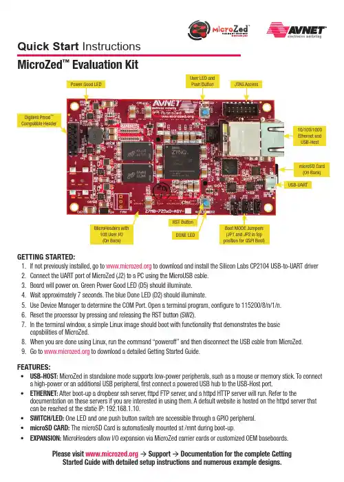
GettinG Started:1. If not previously installed, go to to download and install the Silicon Labs CP2104 USB-to-UART driver2. Connect the UART port of MicroZed (J2) to a PC using the MicroUSB cable.3. Board will power on. Green Power Good LED (D5) should illuminate.4. Wait approximately 7 seconds. The blue Done LED (D2) should illuminate.5. Use Device Manager to determine the COM Port. Open a terminal program, configure to 115200/8/n/1/n.6. Reset the processor by pressing and releasing the RST button (SW2).7.In the terminal window, a simple Linux image should boot with functionality that demonstrates the basic capabilities of MicroZed.8. When you are done using Linux, run the command “poweroff” and then disconnect the USB cable from MicroZed.9. Go to to download a detailed Getting Started Guide.FeatureS:• uSB-HOSt: MicroZed in standalone mode supports low-power peripherals, such as a mouse or memory stick. To connect a high-power or an additional USB peripheral, first connect a powered USB hub to the USB-Host port.• etHernet: After boot-up a dropbear ssh server, fttpd FTP server, and a httpd HTTP server will run. Refer to thedocumentation on these servers if you are interested in using them. A default website is hosted on the httpd server that can be reached at the static IP: 192.168.1.10.• SWitCH/Led: One LED and one push button switch are accessible through a GPIO peripheral.• microSd Card: The microSD Card is automatically mounted at /mnt during boot-up.• eXPanSiOn: MicroHeaders allow I/O expansion via MicroZed carrier cards or customized OEM baseboards.Please visit à Support à documentation for the complete Getting Started Guide with detailed setup instructions and numerous example designs.MicroZed ™ evaluation KitQuick Start InstructionsCopyright © 2013, Avnet, Inc. All rights reserved. Published by Avnet Electronics Marketing, a group of Avnet, Inc. Avnet, Inc. disclaims any proprietary interest or right in any trademarks, service marks, logos, domain names, company names, brands, product names, or other form of intellectual property other than its own. AVNET and the AV logo are registered trademarks of Avnet, Inc. Pn: QSC-Z7MB-7Z010-G-v1LiCenSe aGreeMentTHE AVNET DESIGN KIT (“DESIGN KIT” OR “PRODUCT”) AND ANY SUPPORTING DOCUMENTATION (“DOCUMENTATION” OR “PRODUCT DOCUMENTATION”) IS SUBJECT TO THIS LICENSE AGREEMENT (“LICENSE”). USE OF THE PRODUCT OR DOCUMENTATION SIGNIFIES ACCEPTANCE OF THE TERMS AND CONDITIONS OF THIS LICENSE. The terms of this license Agreement are in addition to the Avnet Customer Terms and Conditions, which can be viewed at . THE TERMS OF THIS LICENSE AGREEMENT WILL CONTROL IN THE EVENT OF A CONFLICT.1.Limited License. Avnet grants You, the Customer, (“You” “Your” or “Customer”) a limited, non-exclusive, non-transferable, license to: (a) use the Product for Your own internal testing, evaluation and design efforts at a single Customer site; (b) create a single derivative work based on theProduct using the same semiconductor supplier product or product family as used in the Product; and (c) make, use and sell the Product in a single production unit. No other rights are granted and Avnet and any other Product licensor reserves all rights not specifically granted in this License Agreement. Except as expressly permitted in this License, neither the Design Kit, Documentation, nor any portion may be reverse engineered,disassembled, decompiled, sold, donated, shared, leased, assigned, sublicensed or otherwise transferred by Customer. The term of this License is in effect until terminated. Customer may terminate this license at any time by destroying the Product and all copies of the Product Documentation.2. Changes. Avnet may make changes to the Product or Product Documentation at any time without notice. Avnet makes no commitment to update or upgrade the Product or Product Documentation and Avnet reserves the right to discontinue the Product or Product Documentation at any time without notice.3.Limited Warranty. ALL products and documentation are provided “AS IS” WITHOUT WARRANTY OF ANY KIND. AVNET MAKES NO WARRANTIES, EITHER EXPRESS OR IMPLIED, WITH RESPECT TO THE PRODUCTS AND DOCUMENTATION PROVIDED HEREUNDER. AVNET SPECIFICALLY DISCLAIMS THE IMPLIED WARRANTIES OF MERCHANTABILITY AND FITNESS FOR A PARTICULAR PURPOSE AND ANY WARRANTY AGAINST INFRINGEMENT OF ANY INTELLECTUAL PROPERTY RIGHT OF ANY THIRD PARTY WITH REGARD TO THE PRODUCTS AND DOCUMENTATION.4.LIMITATIONS OF LIABILITY . CUSTOMER SHALL NOT BE ENTITLED TO AND AVNET WILL NOT LIABLE FOR ANY INDIRECT, SPECIAL, INCIDENTAL OR CONSEQUENTIAL DAMAGES OF ANY KIND OR NATURE, INCLUDING, WITHOUT LIMITATION, BUSINESS INTERRUPTION COSTS, LOSS OF PROFIT OR REVENUE, LOSS OF DATA, PROMOTIONAL OR MANUFACTURING EXPENSES, OVERHEAD, COSTS OR EXPENSES ASSOCIATED WITH WARRANTY OR INTELLECTUAL PROPERTY INFRINGEMENT CLAIMS, INJURY TO REPUTATION OR LOSS OF CUSTOMERS, EVEN IF AVNET HAS BEEN ADVISED OF THE POSSIBILITY OF SUCH DAMAGES. THE PRODUCTS AND DOCUMENTATION ARE NOT DESIGNED, AUTHORIZED OR WARRANTED TO BE SUITABLE FOR USE IN MEDICAL, MILITARY , AIR CRAFT, SPACE OR LIFE SUPPORT EQUIPMENT NOR IN APPLICATIONS WHERE FAILURE OR MALFUNCTION OF THE PRODUCTS CAN REASONABLY BE EXPECTED TO RESULT IN A PERSONAL INJURY , DEATH OR SEVERE PROPERTY OR ENVIRONMENTAL DAMAGE. INCLUSION OR USE OF PRODUCTS IN SUCH EQUIPMENT OR APPLICATIONS, WITHOUT PRIOR AUTHORIZATION IN WRITING OF AVNET, IS NOT PERMITTED AND IS AT CUSTOMER’S OWN RISK. CUSTOMER AGREES TO FULLY INDEMNIFY AVNET FOR ANY DAMAGES RESULTING FROM SUCH INCLUSION OR USE.5. LIMITATION OF DAMAGES. CUSTOMER’S RECOVERY FROM AVNET FOR ANY CLAIM SHALL NOT EXCEED CUSTOMER’S PURCHASE PRICE FOR THEPRODUCT GIVING RISE TO SUCH CLAIM IRRESPECTIVE OF THE NATURE OF THE CLAIM, WHETHER IN CONTRACT, TORT, WARRANTY , OR OTHERWISE.6. INDEMNIFICATION. AVNET SHALL NOT BE LIABLE FOR AND CUSTOMER SHALL INDEMNIFY , DEFEND AND HOLD AVNET HARMLESS FROM ANYCLAIMS BASED ON AVNET’S COMPLIANCE WITH CUSTOMER’S DESIGNS, SPECIFICATIONS OR IN S TRUCTIONS, OR MODIFICATION OF ANY PRODUCT BY PARTIES OTHER THAN AVNET, OR USE IN COMBINATION WITH OTHER PRODUCTS.7. U.S. Government Restricted Rights. The Product and Product Documentation are provided with “RESTRICTED RIGHTS.” If the Product and ProductDocumentation and related technology or documentation are provided to or made available to the United States Government, any use, duplication, or disclosure by the United States Government is subject to restrictions applicable to proprietary commercial computer software as set forth in FAR 52.227-14 and DFAR 252.227-7013, et seq., its successor and other applicable laws and regulations. Use of the Product by the United States Government constitutes acknowledgment of the proprietary rights of Avnet and any third parties. No other governments are authorized to use the Product without written agreement of Avnet and applicable third parties.8. Ownership. Licensee acknowledges and agrees that Avnet or Avnet’s licensors are the sole and exclusive owner of all Intellectual Property Rightsin the Licensed Materials, and Licensee shall acquire no right, title, or interest in the Licensed Materials, other than any rights expressly granted in this Agreement.9. Intellectual Property. All trademarks, service marks, logos, slogans, domain names and trade names (collectively “Marks”) are the properties of theirrespective owners. Avnet disclaims any proprietary interest in Marks other than its own. Avnet and AV design logos are registered trademarks and service marks of Avnet, Inc. Avnet’s Marks may be used only with the prior written permission of Avnet, Inc. 10. General. The terms and conditions set forth in the License Agreement or at will apply notwithstanding any conflicting, contraryor additional terms and conditions in any purchase order, sales acknowledgement confirmation or other document. If there is any conflict, the terms of this License Agreement will control. This License may not be assigned by Customer, by operation of law, merger or otherwise, without the prior written consent of Avnet and any attempted or purported assignment shall be void. Licensee understands that portions of the Licensed Materials may have been licensed to Avnet from third parties and that such third parties are intended beneficiaries of the provisions of thisAgreement. In the event any of the provisions of this Agreement are for any reason determined to be void or unenforceable, the remaining provisions will remain in full effect.This constitutes the entire agreement between the parties with respect to the use of this Product, and supersedes all prior or contemporaneous understandings or agreements, written or oral, regarding such subject matter. No waiver or modification is effective unless agreed to in writing and signed by authorized representatives of both parties. The obligations, rights, terms and conditions shall be binding on the parties and their respective successors and assigns. The License Agreement is governed by and construed in accordance with the laws of the State of Arizona excluding any law or principle, which would apply the law of any other jurisdiction. The United Nations Convention for the International Sale of Goods shall not apply.。

Getting Started GuideGetting started with Active Learn PrimaryWhat is Active Learn Primary?Active Learn Primary is an online learning world where you will find all of our online teaching and learning services. For teachers, it’s a giant repository of teaching material, with in-depth planning, assessment and reporting built in. For children, it’s where they can log in from the classroom and home to find allocated books, games and activities – and earn rewards as they go.Getting started with Active Learn PrimaryActive Learn Primary: In order to help you get up and running, and acquainted with Active Learn Primary as quickly and efficiently as possible, we have created some very short ‘how to’ videos. There are support videos to give you an overview of how to use Active Learn Primary and more specific, product-related videos, for example to show you how to use our Bug Club reading programme.Select from the products in this link to see product-specific overview videos, or see the below summaries of each product.Select from the videos below for a generic overview of Active Learn Primary or click on this link to see all available videos and guidance:•How to login in to Active Learn Primary [watch video]•Overview of products available on Active Learn Primary[watch video]•Overview of Classroom Support area [watch video]•How to add teachers to Active Learn Primary so that they can use the resources [watch video]•How to add pupils to Active Learn Primary so that they can use the resources [watch video]Helpful guidance to send to parents/carersMany parents and carers will be new to the world of online learning, so we have also created some short‘how to’ videos to introduce them to Active Learn Primary. Please do send these links out to parents/carers as necessary.•What is Active Learn Primary and how to log in [watch video]• A quick tour of the pupil world [watch video]•How do rewards work? [watch video]•The grown-ups area [watch video]The Bug Club FamilyThe Bug Club family contains a suite of reading and teaching programmes for children aged 4-11. It covers all reading needs from early reading and phonics through to guided and independent reading, development of deeper text comprehension, and spelling, punctuation and grammar resources.As well as a fantastic online reading world for children, Bug Club also contains a clever online toolkit for teachers. This includes access to all of the eBooks and activities as well as integrated assessment.Find detailed guidance on how to set-up and use Bug Club in this document: (PDF 3.27 MB)Bug Club PhonicsBug Club Phonics is based on a seven-year study in Clackmannanshire, UK, that’s proven systematic phonics to be the most effective way to teach children to read.Bug Club Phonics contains everything you need to teach synthetic phonics to your littlest learners. It isfast-paced – children start to read after learning just eight phonemes – and combines fun, 100% decodable books with BBC CBeebies videos and whole-class teaching software to give you a range of aural, visual and kinaesthetic phonic activities to appeal to all the children in your class.You can:•Search for and allocate resources (eBooks and activities) to classes, groups of children or individual children [watch video ].•Encourage parents to use the parental guidance notes on the inside front and back covers of the eBooks for an enhanced experience, and follow the audio instructions within each phonics game.•Use the activity reporting area to see at a glance how each child performs on the embeddedactivities, whether they enjoyed their reading, and get insights into their progress [watch video ].Parents can:•Learn all about Bug Club Phonics [watch video ].•Learn how to use the Bug Club Phonics eBooks and activities at home [watch video ].•Use the parental guidance notes on the inside front and back covers of the eBooks for an enhanced experience, and follow the audio instructions within each phonics game.Bug Club for Guided Independent Reading (4-11)Bug Club is an engaging, imaginative and finely levelled reading solution for your whole school. We have created some ‘how to’ videos to help you understand the product and enable you to start using it with your class at home.All of the eBooks are levelled according to Letters and Sounds. They also all fit within traditional book band levels. This makes it easy for you to choose which level books to allocate to the children in your class for read-ing practice.You can:•Search for and allocate individual eBooks to classes, groups of children or individual children [watch video ].•Search for and allocate entire book bands of eBooks to classes, groups of children or individual children and sign up for notifications when children need more books [watch video ].•Encourage parents to use the parental guidance notes on the inside front and back covers of the eBooks for an enhanced learning experience for their child.•Use the activity reporting area to see at a glance how each child performs on the embeddedcomprehension activities, whether they enjoyed their reading, and get insights into their progress[watch video ].•If you wish to teach remote Guided Reading lessons with small groups of children, perhaps via anonline video chat service, you can do this with Bug Club. Each eBook has a linked guided reading card which you can work through with children over a number of days. The guided reading cards areavailable as links from each individual eBook within Active Learn Primary. Please note that you cannot currently allocate these for use by parents with children at home.Bug Club KS2 ComprehensionBug Club Comprehension is a fresh approach that helps every child master deep comprehension. It uses a powerful and proven talk-based, mastery approach to help children develop a deeper understanding of texts, regardless of decoding ability.You can:•Use the planning area and allocate resources to children [watch video ].•If you wish to teach remote Guided Reading lessons with your class, allocate eBooks to your class chapter by chapter. Then use the teaching cards for daily discussion.For all Bug Club reading programmes, parents can:•Learn all about Bug Club and the benefits of using it [watch video ]•Learn how to use the Bug Club eBooks [watch video ].•Use the parental guidance notes on the inside front and back covers of the eBooks for an enhanced learning experience for their child.Grammar and Spelling BugGrammar and Spelling Bug is a completely online programme that brings spelling, grammar andpunctuation lessons to life for children aged 5-11, and follows the national curriculum for England. There are comprehensive lesson plans, activities and assessments available atthe click of a button.Built to find the fun in learning grammar, punctuation and spelling, Grammar and Spelling Bug is bursting with online practice games and video tutorials that you can allocate to your class to help them masteressential skills and continue their learning at home. Your children will time travel from Aztec to Victorian times completing exciting practice games again and again, learning key skills at every step without even knowing it!You can:•Learn all about Grammar and Spelling Bug and the benefits of using it [watch video ]•Find and allocate resources to your class [watch video ]Parents can:•Access Grammar and Spelling Bug activities by navigating to the Grammar and Spelling Bug tab inthe My Stuff section of the pupil world [watch video ]Power English: Writing (7-11)Power English: Writing is a new, dynamic KS2 writing approach, which is genre-focused and encourages children to develop writing using their own interests and ideas. Using an evidence-based process which can be applied to all writing, Power English: Writing places a strong emphasis on creativity alongside the technical aspects of writing.Resources available to you on Active Learn Primary are as follows:•An interactive planner, containing lesson plans for individual writing projects along with lesson plans for grammar, punctuation and writing process mini-lessons.•Allocatable, child-facing genre booklets which contain examples and explanations of genre con-ventions as well as helpful prompt questions and hints and tips for generating ideas for writing, drafting, revising, editing and publishing pieces of writing.•Helpful checklists and planning grids which can be allocated to children.•Videos from real-life authors discussing aspects of the genres in which they write.You can:•Use the interactive planner to access lesson plans for individual writing projects and mini-lessons.These lesson plans are especially helpful if you wish to teach online writing lessons with your class.•Learn about the different resources available within Power English: Writing and allocate them to children in your class based on which writing project you would like them to undertake []•Choose a genre you would like your class to focus on, for example fairy tales, and allocate genre booklets to the children to help them create their own fairy tales at home.Parents can:•Access Power English: Writing resources by navigating to the Power English: Writing tab in the My Stuff section of the pupil world [watch video]WordsmithWordsmith is a digital programme for reading comprehension, speaking and listening, grammar and writing, designed to help every child progress. It brings together everything you need to plan, allocate and assess all in one place and includes units on fiction, non-fiction and poetry with detailed, editable lesson plans, resources and e-books.You can:•Allocate resources to a child to look at or work on from home []•Find detailed guidance on how to use Wordsmith in this document: Wordsmith Getting Started Guide (PDF 1.43 MB).•Fiction texts: Try allocating a chapter a week to your students. Look at some of the ideas suggested in the planning or just think of a couple of questions that will encourage them to think about what they have read. For younger students consider getting them to draw pictures, design posters or draw mind maps rather than writing their responses.•Non-fiction texts: These are interactive eBooks that encourage students to explore a ‘Big Question’ in an exciting and dynamic way. Each non-fiction eBook sets out to answer a big question, e.g. in theYear 2 eBook called All About Orang-utans, the students explore the Big Question: Could you keep an orang-utan as a pet? Having explored the eBook, which includes videos and animations, the intention is that they will then have the necessary knowledge to make an informed decision. If you have time, take a look at the planning, which accompanies each book, for suggestion questions, written tasksand challenges. If you prefer not to follow the planning, consider asking the children to keep a logor record (in any format they like) of those facts which they found interesting and didn’t know before.Could those who have access to an iPhone do a 2-3 min recording of what they liked most abouttheir favourite book? Could these be emailed to you and uploaded to your school website?•Poetry: Allocate an age appropriate poem to either be learned off by heart or illustrated. The accompanying lesson plans include lots of suggested activities and links to interactive teachingpages: videos, audio files, drag and drop activities and short compositions. Try using the searchfacility to look for a favourite author, such as Michael Rosen, and allocating the poem and the videoof Michael reading the poem, to your students. Set them the challenge of learning this off by heart,to be delivered with as much expression as Michael. Search for I’m the Youngest in Our House as an example of a poem being read by Michael.Parents can:•Access Wordsmith resources by navigating to the Wordsmith tab in the My Stuff section of the pupil world [watch video].The Rapid FamilyThe Rapid Family is a complete reading, writing and maths solution that is perfect for English Language learners. It consists of an online reading world for children where they can access carefully-levelled eBooks allocated to them by their teacher, as well as a reporting area to help teachers monitor each pupil’s progress remotely.Rapid PhonicsRapid Phonics is based on the successful Sound Discovery phonics catch up programme, and it has been proven in independent studies to help children make accelerated progress in reading and spelling. Rapid Phonics online programme contains a set of fully decodable eBooks that follow the Rapid Phonics progression.Printed books, printed Teaching Guides, phonics flashcards and a phonics wall chart are all available to purchase separately.You can:•Search for and allocate eBooks to groups of children or individual children [].•Encourage parents to help their child practise the key sounds in the book using the activity at the beginning of each book.•Encourage pupils to click on the Rapid Boy or Rapid Girl icons when they appear in the book and follow the audio instructions to complete the activities within the eBooks.•Use the reporting area to see at a glance how each child performs on the embedded activities, whether they have finished the book, and get insights into their progress [watch video].•Learn all about Rapid [watch video].Parents can:•Learn how to use the Rapid Phonics eBooks and activities at home [watch video]•Use the first activity within each book to help their child practise the key sounds they will meet in the book.•Encourage their child to read aloud.•Give their child plenty of praise and encouragement to build their confidence.Rapid ReadingRapid Reading has been proven to help children to make accelerated progress in their word reading and comprehension skills.Rapid Reading online consists of hundreds of eBooks that are all carefully levelled and matched to children’s reading age. The books include fiction and non-fiction texts and cover a range of high-interest topics that will engage even the most reluctant readers. Each eBook includes interactive activities that help children build their word-reading, spelling and comprehension skills.Printed books and printed Teaching Guides are available to purchase separately.Find detailed guidance on how to set-up and use Rapid in this document: Rapid Getting Started Guide (PDF 16.6 MB)You can:•Search for and allocate eBooks to groups of children or individual children [].•Encourage parents to go through the ‘Before Reading’ page of each eBook with their child before beginning the book, although full audio support is included for children who need to access theeBook independently.•Encourage pupils to click on the Rapid Boy or Rapid Girl icons when they appear in the book and follow the audio instructions to complete the activities within the eBooks.•Use the activity reporting area to see at a glance how each child performs on the embedded activities, whether they have finished the book, and get insights into their progress [watch video].•Learn all about Rapid [watch video].Parents can:•Learn how to use the Rapid Reading eBooks and activities at home [watch video].•Use the ‘Before reading’ page of each book to ensure their child has the confidence they need to begin reading.•Encourage their child to read aloud and to complete the activities within each eBook.•Give their child plenty of praise and encouragement to build their confidencePower MathsPower Maths is a mastery programme designed to spark curiosity and excitement in maths. It is recommended by the Department for Education in England and is fully aligned with the White Rose Maths schemes of work, having been developed in partnership.To help teachers set work for children during school closures, we have added free Power Maths content to the Active Learn Secondary website including Textbooks and Practice Book units. Parents/children can access the content via links without signing in. If you are a current Power Maths user, your school will have received an email providing the links.If you do not use Power Maths already, you can get access to the links by completing the form here.These ‘how to’ videos explain how to access and use the content:••For parents and carersAbacusAbacus is a maths scheme for children from Reception to Year 6 (ages 4-11). It has been built by a team of expert authors and teachers to inspire a genuine love of maths and help every child master mathematical concepts. It is written for the primary national curriculum in England and has been built with the outcome of Mastery in mind.Abacus is built around a spiral curriculum so children have the opportunity to revise and practise what they have learnt throughout the year.The planning area contains Long-term, Medium-term, Weekly and Daily plans, which you can export to Word and edit to suit your class.As well as plans, it contains hundreds of resources that you can allocate to the children in your class for practising core skills and improving fluency. For example, there are fun interactive games and pupil videos [watch video], homework sheets and practice powerpointsFind detailed guidance on how to set-up and use Abacus in this document:(PDF 5.29 MB)You can:•Use the planning area to access plans [watch video]•Search for and allocate resources to children in your class [watch video]•Access individual pages from the textbooks (KS2) and workbooks (KS1) in the Resources area•If you are teaching maths lessons remotely, there are links in the plans (online and in Word)to resources relevant to the lessons, such as tools, practice powerpoints and resource sheets.You may want to allocate these to your class in advance of your lesson.Parents can:•Learn all about Abacus [watch video]•Play allocated activities with their children, especially the 414 Talking and Listening activities.Science Bug InternationalScience Bug International is a challenging and complete curriculum programme fromYear 1 to Year 6 (5-11). It contains:•Inspiring plans, hands-on activities, videos, animations and fun activities that children will love.•Detailed support and guidance for every aspect of the UK curriculum ensure retention and mastery of the curriculum standards.•assessment opportunities to help you assess children’s progress and attainment goals. You can:•Learn about the product and start using it with your class at home.•Get an overview of the Science Bug planning area [watch video].Parents can:•Access allocated resources in the Pupil World [watch video].。
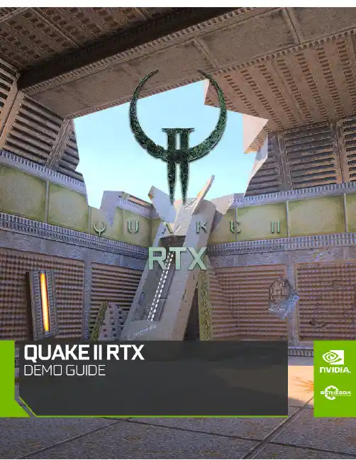
QUAKE II RTX Getting Started tQUAKE II RTX - Getting StartedIntroductionThis guide provides further information about the real-time ray tracing enhancements, and other advanced features, that NVIDIA has implemented to create Q uake II RTX. Most noticeably, we have introduced high-fidelity, real-time path-traced reflections, ambient occlusion, lighting, and shadows, which is a world’s first for any game. For an explanation, c heck out this video:https:///watch?v=p7RniXWvYhYQuake II RTX includes the first 3 levels of the game with our full suite of enhancements. P urchase the full game to get access to all the levels, as well as multiplayer with path-tracing.System RecommendationThe following system configuration, or better, is recommended:●GPU:NVIDIA GeForce RTX 2060 or higher●OS:Windows 10 64 bit or Ubuntu 18.04 LTS 64-bit●CPU:Intel Core i3-3220, or AMD equivalent●RAM:8 GB RAMGetting Started1.)Ensure you have the recommended system specifications2.)Have the latest G ame Ready Driver installed.3.)Install Q uake II RTX.a.)Please see installer instructions below4.)Launch Q uake II RTX via desktop shortcut.5.)Set Recommended Settingsa.)Go to Video -> Set desired Global Illumination Setting (R ecommended: Medium)b.)Set desired resolution (R ecommended: 1080p)c.)Go back and click Game -> Choose desired difficulty.Installer Instructions1.)Windows (Demo)a.)Launch the Q uake II RTX installer executable, or download and run from S teamb.)Make sure that "Quake II Shareware Demo" and "Desktop Shortcut" are both selectedc.)The Installer will install the RTX Demo and leave a shortcut on your desktop.2.)Linux (Demo - Debian / Ubuntu Package)a.)Install the Quake II RTX.deb packageb.)The Installer will install the RTX Demo and leave an icon in your applications menu.3.)Linux (Demo - Steam)a.)Download and run Quake II RTX from SteamEnable Ray Tracing for the Full Game1)Purchase the full game2)Launch the Q uake II RTX installer executable, or download and run from S team3)The installer will detect the Quake II executable location.4)The installer will implement RTX with the full game and leave a shortcut on your desktop.Playing the DemoQuake II RTX is a remaster of the classic game.Quake II R TX i s fully ray-traced (using path tracing), delivering highly realistic lighting, shadows, reflections, global illumination and more.●Start game○Game > Easy●Movement & Weapons○Left Mouse Button = Fire/Attack/Action○W = Forward○ A = Strafe Left○S = Backward○ D = Strafe Right○SPACE = Jump○CTRL = (Holding) = Crouch○SHIFT = Walk (default is run)○ F = Flare gun○G = Grenades●Give weapons and ammo○Press ~ (tilda) button to open the console○/give all = All weapons, ammo, items, keys○/dmflags 8192 = Unlimited Ammo●Show RTX ON/OFF○Show RTX OFF■RTX OFF: V ideo > Renderer > OpenGL■RTX ON: Video > Renderer > rtxMultiplayer SupportQuake II RTX comes with multiplayer support.There are multiple options to play this game in multiplayer mode:1.Join an existing public or private Quake II server online.2.Start a server directly from the game.3.Start a dedicated server and join it.Joining a serverThere are two ways to join an existing server:through the server catalog on ,and manually. The catalog is available through the Multiplayer menu:To join an unlisted server, open the console and type “connect <address>”.If the server is password protected,open the console and type“password<password>”before joining the server.Note that when playing on non-Q2RTX servers, you may observe some compatibility issues: -Rockets and other items may disappear in certain pools of water,which were opaque in the original Quake II;-Flare gun will not be available;-Gameplay mods or custom maps may be incompatible with Q2RTX.Starting a server from the gameIn the multiplayer menu, select “start server”. The following dialog will appear:Starting a dedicated serverQuake II RTX ships with a separate dedicated server executable, “q2rtxded.exe” (on Windows). This is a lightweight version of the game that can only act as a server, but doesn’t allow you to play it directly and doesn’t have any graphics.Simply launching the dedicated server will make it start a deathmatch session on the first available map, which is “base1”. You can change the map and other game settings using the server console, or you can put those commands into a config file and execute that file on server startup using the command line. For example, you can put something like this in a file called “server.cfg” in the baseq2 directory:set password <password>set rcon_password <another_password>set deathmatch 1set coop 0set sv_maplist q2dm1 q2dm2 q2dm3 q2dm4set timelimit 20set fraglimit 20map q2dm1Then start the server using command line:q2rtxded.exe +exec server.cfgServer configurationMany of the console variables useful for dedicated server administration are documented in the Q2PRO server manual- since Quake II RTX is derived from Q2PRO, these variables still apply. We have added some more variables to control RTX specific features:sv_flaregun: controls whether players spawn with the flare gun and ammo for it. 0 means no flare gun, 1 means spawn with the flare gun but no ammo, 2 means spawn with the flare gun and 5 grenades (because the flare gun uses grenades).sv_restrict_rtx: if set to 1, makes the server available only to clients playing Quake II RTX; other clients like the regular Quake II or Q2PRO will be rejected.sv_savedir: path to the directory w ithin baseq2where the server will save game state in cooperative play mode. If multiple dedicated cooperative servers are started from the same installation directory, they should use different directories to save game state.The s v_flaregun and s v_restrict_rtx settings have been added mostly for compatibility reasons. Quake II RTX uses the regular Quake II network protocol (version 36 from Q2PRO), but the flare gun is an extension to the protocol. If both Q2RTX and other clients participate in a multiplayer game, and theQ2RTX user fires a flare gun, other clients that see the flare will disconnect because they do not understand what that means. So it is advised to either disable the flare gun on MP servers, or to make the servers only available to Q2RTX players.© 1997 id Software LLC, a ZeniMax Media company. QUAKE, id, id Software, id Tech and related logos are registered trademarks or trademarks of id Software LLC in the U.S. and/or other countries. Bethesda, Bethesda Softworks, ZeniMax and related logos are registered trademarks or trademarks of ZeniMax Media Inc. in the U.S. and/or other countries. All Rights Reserved.This product is based on or incorporates materials from the sources listed below (third party IP). Such licenses and notices are provided for informational purposes only.Quake II: Copyright (C) 1997-2001 Id Software, Inc. Licensed under the terms of the GPLv2.Q2VKPT: Copyright © 2018 Christoph Schied. Licensed under the terms of the GPLv2.Quake2MaX "A Modscape Production":TexturesfromQuake2MaxusedinQuake2XP.Copyright©*******************************************.SubjecttoCreative Commons license version 1.0. Roughness and specular channels were adjusted in texture maps to work with the Q uake II RTX engine.Q2XP Mod Pack: Used with permission from Arthur Galaktionov.Q2Pro: Copyright © 2003-2011 Andrey Nazarov. Licensed under the terms of the GPLv2.。
DU-05348-001_v6.0 | February 2014Installation and Verification on Mac OS XTABLE OF CONTENTS Chapter 1. Introduction (1)1.1. System Requirements (1)1.2. About This Document (2)Chapter 2. Prerequisites (3)2.1. CUDA-capable GPU (3)2.2. Mac OS X Version (3)2.3. Command-Line T ools (3)Chapter 3. Installation (5)3.1. Download (5)3.2. Install (5)3.3. Uninstall (6)Chapter 4. Verification (7)4.1. Driver (7)4.2. Compiler (7)4.3. Runtime (8)Chapter 5. Additional Considerations (10)CUDA™ is a parallel computing platform and programming model invented by NVIDIA. It enables dramatic increases in computing performance by harnessing the power of the graphics processing unit (GPU).CUDA was developed with several design goals in mind:‣Provide a small set of extensions to standard programming languages, like C, that enable a straightforward implementation of parallel algorithms. With CUDA C/C++, programmers can focus on the task of parallelization of the algorithms rather than spending time on their implementation.‣Support heterogeneous computation where applications use both the CPU and GPU. Serial portions of applications are run on the CPU, and parallel portions are offloaded to the GPU. As such, CUDA can be incrementally applied to existingapplications. The CPU and GPU are treated as separate devices that have their own memory spaces. This configuration also allows simultaneous computation on the CPU and GPU without contention for memory resources.CUDA-capable GPUs have hundreds of cores that can collectively run thousands of computing threads. These cores have shared resources including a register file and a shared memory. The on-chip shared memory allows parallel tasks running on these cores to share data without sending it over the system memory bus.This guide will show you how to install and check the correct operation of the CUDA development tools.1.1. System RequirementsTo use CUDA on your system, you need to have:‣ a CUDA-capable GPU‣Mac OS X 10.8 or later‣the gcc or Clang compiler and toolchain installed using Xcode‣the NVIDIA CUDA Toolkit (available from the CUDA Download page)Introduction T able 1 Mac Operating System Support in CUDA 6.0Before installing the CUDA Toolkit, you should read the Release Notes, as they provide important details on installation and software functionality.1.2. About This DocumentThis document is intended for readers familiar with the Mac OS X environment andthe compilation of C programs from the command line. You do not need previous experience with CUDA or experience with parallel computation.2.1. CUDA-capable GPUTo verify that your system is CUDA-capable, under the Apple menu select AboutThis Mac, click the More Info … button, and then select Graphics/Displays under the Hardware list. There you will find the vendor name and model of your graphics card.If it is an NVIDIA card that is listed on the CUDA-supported GPUs page, your GPU is CUDA-capable.The Release Notes for the CUDA Toolkit also contain a list of supported products.2.2. Mac OS X VersionThe CUDA Development Tools require an Intel-based Mac running Mac OSX v. 10.8 or later. To check which version you have, go to the Apple menu on the desktop and select About This Mac.2.3. Command-Line T oolsThe CUDA Toolkit requires that the native command-line tools (gcc, clang,...) are already installed on the system.To install those command-line tools, Xcode must be installed first. Xcode is available from the Mac App Store.Once Xcode is installed, the command-line tools can be installed by launching Xcode and following those steps:1.Xcode > Preferences... > Downloads > Components2.Install the Command Line Tools packageAlternatively, you can install the command-line tools from the Terminal window by typing the following command: xcode-select --install.PrerequisitesYou can verify that the toolchain is installed by entering the command /usr/bin/cc --help from a Terminal window.3.1. DownloadOnce you have verified that you have a supported NVIDIA GPU, a supported version the MAC OS, and gcc, you need to download the NVIDIA CUDA Toolkit.The NVIDIA CUDA Toolkit is available at no cost from the main CUDA Downloads page. It contains the driver and tools needed to create, build and run a CUDA application as well as libraries, header files, CUDA samples source code, and other resources.The download can be verified by comparing the posted MD5 checksum with that of the downloaded file. If either of the checksums differ, the downloaded file is corrupt and needs to be downloaded again.To calculate the MD5 checksum of the downloaded file, run the following:$ openssl md5 <file>3.2. InstallUse the following procedure to successfully install the CUDA driver and the CUDA toolkit. The CUDA driver and the CUDA toolkit must be installed for CUDA to function. If you have not installed a stand-alone driver, install the driver provided with the CUDA Toolkit.Choose which packages you wish to install. The packages are:‣CUDA Driver: This will install /Library/Frameworks/CUDA.framework and the UNIX-compatibility stub /usr/local/cuda/lib/libcuda.dylib that refers to it.‣CUDA Toolkit: The CUDA Toolkit supplements the CUDA Driver with compilers and additional libraries and header files that are installed into /Developer/ NVIDIA/CUDA-6.0 by default. Symlinks are created in /usr/local/cuda/pointing to their respective files in /Developer/NVIDIA/CUDA-6.0/. PreviousInstallationinstallations of the toolkit will be moved to /Developer/NVIDIA/CUDA-#.# tobetter support side-by-side installations.‣CUDA Samples (read-only): A read-only copy of the CUDA Samples is installed in /Developer/NVIDIA/CUDA-6.0/samples. Previous installations of the samples will be moved to /Developer/NVIDIA/CUDA-#.#/samples to better support side-by-side installations.Set up the required environment variables:export PATH=/Developer/NVIDIA/CUDA-6.0/bin:$PATHexport DYLD_LIBRARY_PATH=/Developer/NVIDIA/CUDA-6.0/lib:$DYLD_LIBRARY_PATHIn order to modify, compile, and run the samples, the samples must also be installed with write permissions. A convenience installation script is provided: cuda-install-samples-6.0.sh. This script is installed with the cuda-samples-6-0 package.3.3. UninstallThe CUDA Driver, Toolkit and Samples can be uninstalled by executing the uninstall script provided with the Toolkit:/Developer/NVIDIA/CUDA-6.0/bin/uninstallBefore continuing, it is important to verify that the CUDA toolkit can find and communicate correctly with the CUDA-capable hardware. To do this, you need to compile and run some of the included sample programs.Ensure the PATH and DYLD_LIBRARY_PATH variables are set correctly.4.1. DriverIf the CUDA Driver is installed correctly, the CUDA kernel extension (/System/ Library/Extensions/CUDA.kext) should be loaded automatically at boot time. To verify that it is loaded, use the commandkextstat | grep -i cuda4.2. CompilerThe installation of the compiler is first checked by running nvcc -V in a terminal window. The nvcc command runs the compiler driver that compiles CUDA programs. It calls the host compiler for C code and the NVIDIA PTX compiler for the CUDA code.On Mac OS 10.8 with XCode 5, nvcc must be invoked with --ccbin=path-to-clang-executable. There are some features that are not yet supported: Clang languageextensions (see /docs/LanguageExtensions.html), LL VM libc++ (only GNU libstdc++ is currently supported), language features introduced in C++11, the __global__ function template explicit instantiation definition, and 32-bitarchitecture cross-compilation.The NVIDIA CUDA Toolkit includes CUDA sample programs in source form. To fully verify that the compiler works properly, a couple of samples should be built. After switching to the directory where the samples were installed, type:Verificationmake -C 0_Simple/vectorAddmake -C 0_Simple/vectorAddDrvmake -C 1_Utilities/deviceQuerymake -C 1_Utilities/bandwidthTestThe builds should produce no error message. The resulting binaries will appear under <dir>/bin/x86_64/darwin/release. To go further and build all the CUDA samples, simply type make from the samples root directory.4.3. RuntimeAfter compilation, go to bin/x86_64/darwin/release and run deviceQuery. Ifthe CUDA software is installed and configured correctly, the output for deviceQuery should look similar to that shown in Figure 1.Figure 1 Valid Results from deviceQuery CUDA SampleNote that the parameters for your CUDA device will vary. The key lines are the first and second ones that confirm a device was found and what model it is. Also, the next-to-last line, as indicated, should show that the test passed.Running the bandwidthTest sample ensures that the system and the CUDA-capable device are able to communicate correctly. Its output is shown in Figure 2VerificationFigure 2 Valid Results from bandwidthT est CUDA SampleNote that the measurements for your CUDA-capable device description will vary from system to system. The important point is that you obtain measurements, and that the second-to-last line (in Figure 2) confirms that all necessary tests passed.Should the tests not pass, make sure you have a CUDA-capable NVIDIA GPU on your system and make sure it is properly installed.If you run into difficulties with the link step (such as libraries not being found), consult the Release Notes found in the doc folder in the CUDA Samples directory.To see a graphical representation of what CUDA can do, run the particles executable.Now that you have CUDA-capable hardware and the NVIDIA CUDA Toolkit installed, you can examine and enjoy the numerous included programs. To begin using CUDA to accelerate the performance of your own applications, consult the CUDA C Programming Guide.A number of helpful development tools are included in the CUDA Toolkit to assistyou as you develop your CUDA programs, such as NVIDIA® Nsight™ Eclipse Edition, NVIDIA Visual Profiler, cuda-gdb, and cuda-memcheck.For technical support on programming questions, consult and participate in the Developer Forums.NoticeALL NVIDIA DESIGN SPECIFICATIONS, REFERENCE BOARDS, FILES, DRAWINGS, DIAGNOSTICS, LISTS, AND OTHER DOCUMENTS (TOGETHER AND SEPARATEL Y, "MATERIALS") ARE BEING PROVIDED "AS IS." NVIDIA MAKES NO WARRANTIES, EXPRESSED, IMPLIED, STATUTORY, OR OTHERWISE WITH RESPECT TO THE MATERIALS, AND EXPRESSL Y DISCLAIMS ALL IMPLIED WARRANTIES OF NONINFRINGEMENT, MERCHANTABILITY, AND FITNESS FOR A PARTICULAR PURPOSE.Information furnished is believed to be accurate and reliable. However, NVIDIA Corporation assumes no responsibility for the consequences of use of such information or for any infringement of patents or other rights of third parties that may result from its use. No license is granted by implication of otherwise under any patent rights of NVIDIA Corporation. Specifications mentioned in this publication are subject to change without notice. This publication supersedes and replaces all other information previously supplied. NVIDIA Corporation products are not authorized as critical components in life support devices or systems without express written approval of NVIDIA Corporation.TrademarksNVIDIA and the NVIDIA logo are trademarks or registered trademarks of NVIDIA Corporation in the U.S. and other countries. Other company and product names may be trademarks of the respective companies with which they are associated. Copyright© 2009-2014 NVIDIA Corporation. All rights reserved.。
Getting Started GuideWelcome to updated Security Management capabilities in CitiDirect BE®. This guide is intendedto provide an overview of recent enhancements and important information that will allow you to begin using the new capabilities today.NavigationEnhanced navigation vastly reduces the number of menu items to select and makes it easierto navigate between functions. Under Self Service/Client Administration Service, two newmenu items are available: User & Entitlements and Client Settings. Clicking on either of these items loads a left-hand navigation panel that can be used to access all CitiDirect BE Security Management functions.To use the new left-hand navigation, point to a section (e.g. Users & Entitlements), and available options will load. Point to the next item (e.g. Users), and options such as Create, Authorize, All will appear based on your entitlements.New visual indicators let you know if you have any records pending authorization or repair, or pending in draft status.You can continue to use the left navigation panel for all the Client Administration Service screens without needing to use the top menu.Tip: To see records pending your action, load the left navigation panel by selecting Self Service/ Client Administration Service/Users & Entitlements. A gold dot or number will appear on the navigation panel guiding you to pending actions.Note: Pilot and Early Adopter users will retain access to the current and new menu items until late 2015, after which time only the User & Entitlements and Client Settings menu items willbe maintained.Naming Convention UpdatesEntitlements is the new name for User Groups. User Entitlement Associations is the new name for User Group Association. Based on feedback from our users, the name User Groups was misleading, so we renamed it as Entitlements to better reflect the functionality.ListsThe Worklists and the View All lists have been combined into a single feature.The ‘All lists’, such as All Users or All Entitlements, provide all records, including Processed, pending Authorization, Repair and Draft. If a user has Input access, he/she will be able to clickon a record and modify the existing processed record (unless locked for authorization). If a user has View Only access to Users, she will be able to access All Users, select users by clicking on the name, and see a read-only display of the record.‘Authorize Lists’ display only records pending Authorization. The Authorize lists allow you to review a record in detail, review changes, as well as Authorize, Send to Repair, or Reject a record.Tip: If you have multiple users to authorize and want to save time, from the Authorize list: 1) select the checkboxes next to all the records you need to authorize, and 2) click on the first of the selected records to access detail view. You will be brought to the detail view of the first record. After you authorize each record, the detail view of the next selected record will appear so you no longer need to go back to the list after viewing each record.‘Modify/Repair lists’ displays records either in Draft (record was saved instead of submitted)or in Repair (sent for repair by authorizer). Modify/Repair lists allow you to Submit or Save a pending record.Confirmation MessagesNew, intuitive confirmation and error messages will appear after you click Submit on records.A green banner will appear at the top of the screen for confirmations. This banner will disappear after 20 seconds, and will be located at the top of the screen so you can continue working without needing to click OK to acknowledge the message or clear a pop-up box.Single Screen User CreationUser creation has been enhanced to save you time. If your client is set up for CitiDirect Services, a new panel is available in Create User so you can assign Access Profiles to users, and avoid the second step in CitiDirect Services.Going forward to create a user in CitiDirect BE:1. Go to Create Usera. Enter User profile and contact informationb. Select credentialsc. Select Entitlements (formerly User Groups)d. Select Access Profiles2. Submit the Create User form3. Ask a second Security Manager to authorize the user in the Authorize User list4. User setup is completeThe Create User screen is divided into panels to guide you through necessary tasks, and instructional text has been added throughout. As you complete required portions of a section, the next panel is enabled, and can be expanded for data entry.Sections will continue to include auto-population logic, so the address, credentials, and entitlements (formerly User Groups) will be pre-populated.Key Changes in User creation:New address logic is designed to save time and prevent data entry issues. The address from your client record will be pre-populated, and only the Building/Floor/Room field will be open for editing. If you are satisfied with the address, check the box directly under the address. If the address needs to be changed, click on Create New Address.The default ‘Global Service Group’ entitlement (formerly User Group) is no longer visible or required. It will not appear on your existing users in the new screens, and will not be available for your new users. This entitlement provided access to My Settings, and we have updated the system so this no longer needs to be explicitly entitled.Tip: You can manage existing users Entitlements and Access Profiles from this screen. Go to the All User list, click on the processed user record. Modify the Entitlements and Access Profiles, and then submit the user record.Note: The creation and maintenance of Access Profiles and Flow Maintenance needs to be completed in CitiDirect Services. Associating users to Access Profiles can be completed in the new screens or in CitiDirect Services. If a User record including Access Profiles was input in Client Administration Service, it needs to be Authorized in the same system, and the user entitlement record will be locked in CitiDirect Services. If an entitlement record was submitted in CitiDirect Services, it needs to be authorized in CitiDirect Services.Use the default address (click the checkbox for ‘The above address is correct’ to indicate you reviewed and confirm the address, or click on Create New Address to make address fields editable for data entry.Allow access: default end date is 5 years from today, 24 hours a day, and all days of the week are selected by default.Appropriate credentials are added. Use drop downs and fields to define settings as needed, and click on Add Credentials button to add more credentials.Assign entitlements by selecting an entitlement in the left panel, and clicking the Add button to move to the right panel. Default entitlements (like CitiDirect Services) will be pre-assigned, and appear in the right panel.NEW! Assign CitiDirect Services Access Profiles by selecting Access Profiles in the left panel, and clicking the Add button to move to the right panel.Click the Submit button when complete, andask another Security Manager to authorize theCreate User Entitlement AssociationUser Entitlement Association has been redesigned to make it easier to grant or remove entitlements from many users at once. Because of the diverse needs of our clients, two different interfaces have been designed.Large scale clients (50 or more users and/or 15 or more user groups) will see the card method, and clients with less than 50 users and 15 entitlements (formerly known as user groups) have access to both the grid method and the card method.Card MethodIn the Card Method, select users you want to manage on the left, and select entitlements you want to add on the right. Click the Associate button to create user cards in the bottom of the screen. Hover over and click the edit button on a card to make changes to the users entitlements if needed. Click Submit when complete.Grid MethodGrid method is a powerful tool to review and modify entitlements. When loaded, a user’s existing entitlements appear as green checkmarks. Click a user row to add or remove entitlements. When satisfied with all user entitlements, click Submit.Tip: For clients with access to both displays, Grid Method display will load by default. There is a button on the upper left of the screen (Switch to Card Method and Switch to Grid Method) that allows you to toggle displays to best meet your needs.Card Method DisplayTip: Give all your users a new entitlement in only 4 clicks using the Card method. If you need to give all your users a new entitlement, select the all user checkbox on the left (above all user names), and select the new entitlement on the right, and click associate. Click submit on the bottom of the screen.Grid Method DisplayTip: Grid method is an easy way to review entitlements. If you want to confirm all your users have an entitlement, go to Create Entitlement Association (grid method) to visually review entitlements by ensuring all the boxes are checked under that entitlement.Create EntitlementsIn the redesigned Create Entitlements screen, you can define and group entitlements all in one screen. To use the new screen, select the services you would like in a group on the left, and move the services to the right to further configure.Select Entitlements in the left panel, press the add button.After Services are selected, configure details on the right to define. All available parameters will display so you have visibility into all your options. You may configure at the service level, or opt to configure each subcategory individually using the toggle buttons.Tip: Use the Expand All and Collapse All buttons to save time avoid needing to expanditems individually.CitiDirect BE AlertsYou can now send Alerts to other Users within your client. Alerts can be delivered either via a popup message when users login and/or can be sent via email. Alerts are a handy way to request authorization for pending records, or to communicate information to your user base. By default, Security Managers are being granted entitlements to access the Alert capability. You can grant the Create Alert entitlements to other users as desired.To create an Alert:1. Select “Self Service” > “Alerts” > “Create Alert” from the menu2. Choose how the Alert should be delivered (if you choose “Display on Homepage”, you shouldset an “Expiry Date” for the Alert up to a maximum of 30 days from the date on which you set-up the Alert)3. Select the Users who should receive the Alert4. Enter a Subject and Details5. Click “Submit”The two images below are examples of how the Alert is presented to the recipient at login (left) and via email (right).To grant entitlements to your users, associate the users to an entitlement that includes Service/ Subservice: Communications/Alert Creation.Control Email DomainsCitiDirect BE now supports the ability to set acceptable email domains for your users. By defining email domains for your client, you can control which emails are entered in Create User and inMy Settings (where users may input their own email addresses — available in limited countries). Additionally, if email domains have been enabled for your client, you can ensure that CitiDirect BE Alerts are only emailed to users with email addresses that fall into your preferred domains.To define your email domains, go to Self Service/Client Administration Service/Client Settings. Once the left navigation panel loads, point to Client Settings, Client Preferences, then click on All Client Preferences.Click in the Global service to open the detail screen with available options. In the Email Domain field, enter one or more domains separated by a comma (,), semicolon (;) or space ( ).Click Submit when complete, and your changes will be sent for Authorization. The record must be authorized. Note: existing user records will be impacted if you attempt to modify the user record and that user has an email address that falls out of the domain rules. In this case, you will receive an error message when you try to submit the user record.Treasury and Trade Solutions/treasuryandtradesolutions。
CUDA 4.0The ‘Super’ Computing Company From Super Phones to Super ComputersCUDA 4.0 for Broader Developer AdoptionCUDA 4.0Application Porting Made SimplerRapid Application PortingUnified Virtual Addressing Faster Multi-GPU ProgrammingNVIDIA GPUDirect™ 2.0 Easier Parallel Programming in C++ThrustCUDA 4.0: Highlights•Share GPUs across multiple threads •Single thread access to all GPUs •No-copy pinning of system memory •New CUDA C/C++ features•Thrust templated primitives library •NPP image/video processing library •Layered TexturesEasier Parallel Application Porting•Auto Performance Analysis •C++ Debugging•GPU Binary Disassembler•cuda-gdb for MacOSNew & ImprovedDeveloper Tools•NVIDIA GPUDirect™ v2.0•Peer-to-Peer Access •Peer-to-Peer Transfers•Unified Virtual AddressingFasterMulti-GPU ProgrammingEasier Porting of Existing ApplicationsShare GPUs across multiple threadsEasier porting of multi-threaded appspthreads / OpenMP threads share a GPULaunch concurrent kernels fromdifferent host threadsEliminates context switching overheadNew, simple context management APIsOld context migration APIs still supported Single thread access to all GPUs Each host thread can now access allGPUs in the systemOne thread per GPU limitation removedEasier than ever for applications totake advantage of multi-GPUSingle-threaded applications can nowbenefit from multiple GPUsEasily coordinate work across multipleGPUs (e.g. halo exchange)No-copy Pinning of System MemoryReduce system memory usage and CPU memcpy() overheadEasier to add CUDA acceleration to existing applications Just register malloc’d system memory for async operations and then call cudaMemcpy() as usualAll CUDA-capable GPUs on Linux or WindowsRequires Linux kernel 2.6.15+ (RHEL 5)Before No-copy Pinning With No-copy Pinning Extra allocation and extra copy requiredJust register and go!cudaMallocHost(b) memcpy(b, a) memcpy(a, b) cudaFreeHost(b)cudaHostRegister(a)cudaHostUnregister(a)cudaMemcpy() to GPU, launch kernels, cudaMemcpy() from GPU malloc(a)New CUDA C/C++ Language FeaturesC++ new/deleteDynamic memory managementC++ virtual functionsEasier porting of existing applicationsInline PTXEnables assembly-level optimizationC++ Templatized Algorithms & Data Structures (Thrust) Powerful open source C++ parallel algorithms & data structures Similar to C++ Standard Template Library (STL)Automatically chooses the fastest code path at compile time Divides work between GPUs and multi-core CPUsParallel sorting @ 5x to 100x fasterData Structures •thrust::device_vector •thrust::host_vector •thrust::device_ptr •Etc.Algorithms •thrust::sort •thrust::reduce •thrust::exclusive_scan •Etc.NVIDIA Performance Primitives (NPP) library10x to 36x faster image processingInitial focus on imaging and video related primitivesGPU-Accelerated Image ProcessingData exchange & initialization Set, Convert, CopyConstBorder, Copy, Transpose, SwapChannelsColor ConversionRGB To YCbCr (& vice versa),ColorTwist, LUT_LinearThreshold & Compare OpsThreshold, CompareStatisticsMean, StdDev, NormDiff, MinMax,Histogram,SqrIntegral, RectStdDev Filter FunctionsFilterBox, Row, Column, Max, Min, Median, Dilate, Erode, SumWindowColumn/RowGeometry TransformsMirror, WarpAffine / Back/ Quad,WarpPerspective / Back / Quad, ResizeArithmetic & Logical OpsAdd, Sub, Mul, Div, AbsDiffJPEGDCTQuantInv/Fwd, QuantizationTableLayered Textures – Faster Image ProcessingIdeal for processing multiple textures with same size/format Large sizes supported on Tesla T20 (Fermi) GPUs (up to 16k x 16k x 2k)e.g. Medical Imaging, Terrain Rendering (flight simulators), etc.Faster PerformanceReduced CPU overhead: single binding for entire texture arrayFaster than 3D Textures: more efficient filter cachingFast interop with OpenGL / Direct3D for each layerNo need to create/manage a texture atlasNo sampling artifactsLinear/Bilinear filtering applied only within a layerCUDA 4.0: Highlights•Auto Performance Analysis •C++ Debugging•GPU Binary Disassembler•cuda-gdb for MacOSNew & ImprovedDeveloper Tools•Share GPUs across multiple threads •Single thread access to all GPUs •No-copy pinning of system memory •New CUDA C/C++ features•Thrust templated primitives library •NPP image/video processing library •Layered TexturesEasier Parallel Application Porting•NVIDIA GPUDirect™ v2.0•Peer-to-Peer Access •Peer-to-Peer Transfers•Unified Virtual AddressingFasterMulti-GPU ProgrammingNVIDIA GPUDirect™:Towards Eliminating the CPU Bottleneck•Direct access to GPU memory for 3rd party devices•Eliminates unnecessary sys mem copies & CPU overhead•Supported by Mellanox and Qlogic •Up to 30% improvement in communication performanceVersion 1.0for applications that communicateover a network•Peer-to-Peer memory access, transfers & synchronization•Less code, higher programmer productivityVersion 2.0for applications that communicatewithin a nodeBefore NVIDIA GPUDirect™ v2.0Required Copy into Main MemoryGPU 1GPU 1 MemoryGPU 2GPU 2 MemoryPCI-eCPUChip System MemoryTwo copies required:1. cudaMemcpy(GPU2, sysmem)2. cudaMemcpy(sysmem, GPU1)NVIDIA GPUDirect™ v2.0:Peer-to-Peer CommunicationDirect Transfers between GPUsGPU 1GPU 1 MemoryGPU 2GPU 2 MemoryPCI-eCPUChip System MemoryOnly one copy required:1. cudaMemcpy(GPU2, GPU1)GPUDirect v2.0: Peer-to-Peer CommunicationDirect communication between GPUsFaster - no system memory copy overheadMore convenient multi-GPU programmingDirect TransfersCopy from GPU0 memory to GPU1 memoryWorks transparently with UVADirect AccessGPU0 reads or writes GPU1 memory (load/store)Supported on Tesla 20-series and other Fermi GPUs 64-bit applications on Linux and Windows TCCUnified Virtual AddressingEasier to Program with Single Address SpaceNo UVA: Multiple Memory SpacesUVA : Single Address SpaceSystem MemoryCPU GPU 0 GPU 0 MemoryGPU 1 GPU 1 MemorySystem MemoryCPU GPU 0 GPU 0 Memory GPU 1GPU 1 MemoryPCI-ePCI-e0x0000 0xFFFF0x0000 0xFFFF0x0000 0xFFFF0x00000xFFFFUnified Virtual AddressingOne address space for all CPU and GPU memoryDetermine physical memory location from pointer valueEnables libraries to simplify their interfaces (e.g. cudaMemcpy)Supported on Tesla 20-series and other Fermi GPUs64-bit applications on Linux and Windows TCCBefore UVA With UVASeparate options for each permutation One function handles all cases cudaMemcpyHostToHost cudaMemcpyHostToDevice cudaMemcpyDeviceToHost cudaMemcpyDeviceToDevicecudaMemcpyDefault(data location becomes an implementation detail)CUDA 4.0: Highlights•NVIDIA GPUDirect™ v2.0•Peer-to-Peer Access •Peer-to-Peer Transfers•Unified Virtual AddressingFasterMulti-GPU Programming•Share GPUs across multiple threads •Single thread access to all GPUs •No-copy pinning of system memory •New CUDA C/C++ features•Thrust templated primitives library •NPP image/video processing library •Layered TexturesEasier Parallel Application Porting•Auto Performance Analysis •C++ Debugging•GPU Binary Disassembler•cuda-gdb for MacOSNew & ImprovedDeveloper ToolsAutomated Performance Analysis in Visual ProfilerSummary analysis & hintsSessionDeviceContextKernelNew UI for kernel analysisIdentify limiting factorAnalyze instruction throughputAnalyze memory throughputAnalyze kernel occupancyNew Features in cuda-gdbFermidisassemblyBreakpoints on all instances of templated functionsC++ symbols shown in stack trace viewNow available for both Linux and MacOSinfo cuda threadsautomatically updated in DDD(cuobjdump)cuda-gdb Now Available for MacOSDetails @ /object/cuda-gdb.htmlNVIDIA Parallel Nsight™ Pro 1.5ProfessionalCUDA Debugging ✓Compute Analyzer ✓CUDA / OpenCL Profiling ✓Tesla Compute Cluster (TCC) Debugging ✓Tesla Support: C1050/S1070 or higher ✓Quadro Support: G9x or higher ✓Windows 7, Vista and HPC Server 2008 ✓Visual Studio 2008 SP1 and Visual Studio 2010 ✓OpenGL and OpenCL Analyzer ✓DirectX 10 & 11 Analyzer, Debugger & Graphics✓inspectorGeForce Support: 9 series or higher ✓CUDA Registered Developer ProgramAll GPGPU developers should become NVIDIA Registered Developers Benefits include:Early Access to Pre-Release SoftwareBeta software and librariesCUDA 4.0 Release Candidate available nowSubmit & Track Issues and BugsInteract directly with NVIDIA QA engineersNew benefits in 2011Exclusive Q&A Webinars with NVIDIA EngineeringExclusive deep dive CUDA training webinarsIn-depth engineering presentations on pre-release softwareAdditional Information…CUDA Features OverviewCUDA Developer Resources from NVIDIACUDA 3rd Party EcosystemPGI CUDA x86GPU Computing Research & EducationNVIDIA Parallel Developer ProgramGPU Technology Conference 2011CUDA Features OverviewNew in CUDA 4.0Hardware Features ECC Memory Double PrecisionNative 64-bit Architecture Concurrent Kernel Execution Dual Copy Engines6GB per GPU supportedOperating System Support MS Windows 32/64 Linux 32/64 Mac OS X 32/64Designed for HPC Cluster Management GPUDirectT esla Compute Cluster (TCC) Multi-GPU supportGPUDirect tm (v 2.0)Peer-Peer CommunicationPlatformC supportNVIDIA C CompilerCUDA C Parallel Extensions Function Pointers Recursion Atomics malloc/freeC++ supportClasses/Objects Class Inheritance PolymorphismOperator Overloading Class Templates Function Templates Virtual Base Classes NamespacesFortran supportCUDA Fortran (PGI)Unified Virtual Addressing C++ new/deleteC++ Virtual FunctionsProgramming ModelNVIDIA Library SupportComplete math.h Complete BLAS Library (1, 2 and 3)Sparse Matrix Math LibraryRNG LibraryFFT Library (1D, 2D and 3D)Video Decoding Library (NVCUVID)Video Encoding Library (NVCUVENC)Image Processing Library (NPP)Video Processing Library (NPP) 3rd Party Math Libraries CULA T ools (EM Photonics) MAGMA Heterogeneous LAPACK IMSL (Rogue Wave) VSIPL (GPU VSIPL) Thrust C++ LibraryTemplated Performance Primitives LibraryParallel LibrariesNVIDIA Developer T oolsParallel Nsightfor MS Visual Studio cuda-gdb Debugger with multi-GPU support CUDA/OpenCL Visual Profiler CUDA Memory Checker CUDA DisassemblerGPU Computing SDKNVMLCUPTI 3rd Party Developer T ools Allinea DDT RogueWave /T otalview Vampir T auCAPS HMPPParallel Nsight Pro 1.5Development T oolsCUDA Developer Resources from NVIDIALibraries and EnginesMath LibrariesCUFFT, CUBLAS, CUSPARSE, CURAND, math.h 3rd Party LibrariesCULA LAPACK, VSIPL NPP Image LibrariesPerformance primitives for imagingApp Acceleration Engines Ray Tracing: Optix, iRayVideo Encoding / DecodingNVCUVENC / VCUVIDDevelopmentT oolsCUDA T oolkit Complete GPU computing development kit cuda-gdbGPU hardware debuggingcuda-memcheck Identifies memory errors cuobjdumpCUDA binary disassembler Visual ProfilerGPU hardware profiler for CUDA C and OpenCLParallel Nsight ProIntegrated developmentenvironment for Visual StudioSDKs and Code SamplesGPU Computing SDKCUDA C/C++, DirectCompute, OpenCL code samples and documentationBooksCUDA by Example GPU Computing Gems Programming Massively Parallel Processors Many more…Optimization GuidesBest Practices for GPU computing and graphics developmentCUDA 3rd Party EcosystemParallel DebuggersMS Visual Studio withParallel Nsight ProAllinea DDT DebuggerT otalView Debugger Parallel Performance T ools ParaT ools VampirTrace TauCUDA Performance T ools PAPIHPC T oolkit Cloud Providers Amazon EC2Peer 1OEM’sDellHPIBMInfiniband Providers MellanoxQLogicCluster Management Platform HPCPlatform Symphony Bright Cluster manager Ganglia Monitoring System Moab Cluster SuiteAltair PBS ProJob SchedulingAltair PBSproTORQUEPlatform LSFMPI LibrariesComing soon…PGI CUDA FortranPGI Accelerator (C/Fortran) PGI CUDA x86CAPS HMPPpyCUDA (Python) Tidepowerd (C#) JCuda (Java)Khronos OpenCLMicrosoft DirectCompute3rd Party Math Libraries CULA T ools (EM Photonics) MAGMA Heterogeneous LAPACK IMSL (Rogue Wave)VSIPL (GPU VSIPL)NAGCluster T ools Parallel LanguageSolutions & APIs Parallel T ools Compute Platform ProvidersPGI CUDA x86 Compiler BenefitsDeploy CUDA apps onlegacy systems without GPUsLess code maintenancefor developersTimelineApril/May 1.0 initial releaseDevelop, debug, test functionalityAug 1.1 performance releaseMulticore, SSE/AVX supportProven Research Vision John Hopkins University Nanyan University Technical University-Czech CSIRO SINTEF HP Labs ICHECBarcelona SuperComputer Center Clemson University Fraunhofer SCAIKarlsruhe Institute Of TechnologyWorld Class Research Leadership and Teaching University of Cambridge Harvard University University of Utah University of Tennessee University of MarylandUniversity of Illinois at Urbana-Champaign Tsinghua UniversityTokyo Institute of Technology Chinese Academy of Sciences National Taiwan University Georgia Institute of TechnologyGPGPU Education 350+ UniversitiesAcademic Partnerships / FellowshipsGPU Computing Research & EducationMass. Gen. Hospital/NE Univ North Carolina State University Swinburne University of Tech. Techische Univ. Munich UCLAUniversity of New Mexico University Of Warsaw-ICMVSB-Tech University of Ostrava And more coming shortly.“Don’t kid yourself. GPUs are a game-changer.” said Frank Chambers, a GTC conference attendee shopping for GPUs for his finite element analysis work. “What we are seeing here is like going from propellers to jet engines. That made transcontinental flights routine. Wide access to this kind of computing power is making things like artificial retinas possible, and that wasn’t predicted to happen until 2060.”- Inside HPC (Sept 22, 2010)GPU Technology Conference 2011October 11-14 | San Jose, CAThe one event you can’t afford to miss▪Learn about leading-edge advances in GPU computing▪Explore the research as well as the commercial applications▪Discover advances in computational visualization▪T ake a deep dive into parallel programmingWays to participate▪Speak – share your work and gain exposure as a thought leader▪Register – learn from the experts and network with your peers▪Exhibit/Sponsor – promote your company as a key player in the GPU ecosystem。
Design GuideChanges from Version 11.0‣Added documentation for Compute Capability 8.x.‣Updated section Arithmetic Instructions for compute capability 8.6.‣Updated section Features and Technical Specifications for compute capability 8.6.Table of Contents Chapter 1. Introduction (1)1.1. The Benefits of Using GPUs (1)1.2. CUDA®: A General-Purpose Parallel Computing Platform and Programming Model (2)1.3. A Scalable Programming Model (3)1.4. Document Structure (5)Chapter 2. Programming Model (7)2.1. Kernels (7)2.2. Thread Hierarchy (8)2.3. Memory Hierarchy (10)2.4. Heterogeneous Programming (11)2.5. Compute Capability (14)Chapter 3. Programming Interface (15)3.1. Compilation with NVCC (15)3.1.1. Compilation Workflow (16)3.1.1.1. Offline Compilation (16)3.1.1.2. Just-in-Time Compilation (16)3.1.2. Binary Compatibility (17)3.1.3. PTX Compatibility (17)3.1.4. Application Compatibility (17)3.1.5. C++ Compatibility (18)3.1.6. 64-Bit Compatibility (18)3.2. CUDA Runtime (19)3.2.1. Initialization (19)3.2.2. Device Memory (20)3.2.3. Device Memory L2 Access Management (23)3.2.3.1. L2 cache Set-Aside for Persisting Accesses (23)3.2.3.2. L2 Policy for Persisting Accesses (23)3.2.3.3. L2 Access Properties (25)3.2.3.4. L2 Persistence Example (25)3.2.3.5. Reset L2 Access to Normal (26)3.2.3.6. Manage Utilization of L2 set-aside cache (27)3.2.3.7. Query L2 cache Properties (27)3.2.3.8. Control L2 Cache Set-Aside Size for Persisting Memory Access (27)3.2.4. Shared Memory (27)3.2.5. Page-Locked Host Memory (33)3.2.5.1. Portable Memory (33)3.2.5.2. Write-Combining Memory (33)3.2.5.3. Mapped Memory (34)3.2.6. Asynchronous Concurrent Execution (35)3.2.6.1. Concurrent Execution between Host and Device (35)3.2.6.2. Concurrent Kernel Execution (35)3.2.6.3. Overlap of Data Transfer and Kernel Execution (36)3.2.6.4. Concurrent Data Transfers (36)3.2.6.5. Streams (36)3.2.6.6. CUDA Graphs (40)3.2.6.7. Events (48)3.2.6.8. Synchronous Calls (49)3.2.7. Multi-Device System (49)3.2.7.1. Device Enumeration (49)3.2.7.2. Device Selection (50)3.2.7.3. Stream and Event Behavior (50)3.2.7.4. Peer-to-Peer Memory Access (51)3.2.7.5. Peer-to-Peer Memory Copy (51)3.2.8. Unified Virtual Address Space (52)3.2.9. Interprocess Communication (52)3.2.10. Error Checking (53)3.2.11. Call Stack (54)3.2.12. Texture and Surface Memory (54)3.2.12.1. Texture Memory (54)3.2.12.2. Surface Memory (63)3.2.12.3. CUDA Arrays (66)3.2.12.4. Read/Write Coherency (66)3.2.13. Graphics Interoperability (66)3.2.13.1. OpenGL Interoperability (67)3.2.13.2. Direct3D Interoperability (69)3.2.13.3. SLI Interoperability (74)3.2.14. External Resource Interoperability (75)3.2.14.1. Vulkan Interoperability (75)3.2.14.2. OpenGL Interoperability (83)3.2.14.3. Direct3D 12 Interoperability (83)3.2.14.4. Direct3D 11 Interoperability (89)3.2.14.5. NVIDIA Software Communication Interface Interoperability (NVSCI) (96)3.3. Versioning and Compatibility (100)3.5. Mode Switches (102)3.6. Tesla Compute Cluster Mode for Windows (103)Chapter 4. Hardware Implementation (104)4.1. SIMT Architecture (104)4.2. Hardware Multithreading (106)Chapter 5. Performance Guidelines (107)5.1. Overall Performance Optimization Strategies (107)5.2. Maximize Utilization (107)5.2.1. Application Level (107)5.2.2. Device Level (108)5.2.3. Multiprocessor Level (108)5.2.3.1. Occupancy Calculator (110)5.3. Maximize Memory Throughput (111)5.3.1. Data Transfer between Host and Device (112)5.3.2. Device Memory Accesses (113)5.4. Maximize Instruction Throughput (117)5.4.1. Arithmetic Instructions (117)5.4.2. Control Flow Instructions (122)5.4.3. Synchronization Instruction (123)Appendix A. CUDA-Enabled GPUs (124)Appendix B. C++ Language Extensions (125)B.1. Function Execution Space Specifiers (125)B.1.1. __global__ (125)B.1.2. __device__ (125)B.1.3. __host__ (125)B.1.4. Undefined behavior (126)B.1.5. __noinline__ and __forceinline__ (126)B.2. Variable Memory Space Specifiers (127)B.2.1. __device__ (127)B.2.2. __constant__ (127)B.2.3. __shared__ (127)B.2.4. __managed__ (128)B.2.5. __restrict__ (128)B.3. Built-in Vector Types (130)B.3.1. char, short, int, long, longlong, float, double (130)B.3.2. dim3 (131)B.4.1. gridDim (131)B.4.2. blockIdx (131)B.4.3. blockDim (131)B.4.4. threadIdx (131)B.4.5. warpSize (132)B.5. Memory Fence Functions (132)B.6. Synchronization Functions (134)B.7. Mathematical Functions (135)B.8. Texture Functions (136)B.8.1. Texture Object API (136)B.8.1.1. tex1Dfetch() (136)B.8.1.2. tex1D() (136)B.8.1.3. tex1DLod() (136)B.8.1.4. tex1DGrad() (136)B.8.1.5. tex2D() (136)B.8.1.6. tex2DLod() (137)B.8.1.7. tex2DGrad() (137)B.8.1.8. tex3D() (137)B.8.1.9. tex3DLod() (137)B.8.1.10. tex3DGrad() (137)B.8.1.11. tex1DLayered() (137)B.8.1.12. tex1DLayeredLod() (137)B.8.1.13. tex1DLayeredGrad() (138)B.8.1.14. tex2DLayered() (138)B.8.1.15. tex2DLayeredLod() (138)B.8.1.16. tex2DLayeredGrad() (138)B.8.1.17. texCubemap() (138)B.8.1.18. texCubemapLod() (138)B.8.1.19. texCubemapLayered() (139)B.8.1.20. texCubemapLayeredLod() (139)B.8.1.21. tex2Dgather() (139)B.8.2. Texture Reference API (139)B.8.2.1. tex1Dfetch() (139)B.8.2.2. tex1D() (140)B.8.2.3. tex1DLod() (140)B.8.2.4. tex1DGrad() (140)B.8.2.5. tex2D() (140)B.8.2.7. tex2DGrad() (141)B.8.2.8. tex3D() (141)B.8.2.9. tex3DLod() (141)B.8.2.10. tex3DGrad() (141)B.8.2.11. tex1DLayered() (142)B.8.2.12. tex1DLayeredLod() (142)B.8.2.13. tex1DLayeredGrad() (142)B.8.2.14. tex2DLayered() (142)B.8.2.15. tex2DLayeredLod() (143)B.8.2.16. tex2DLayeredGrad() (143)B.8.2.17. texCubemap() (143)B.8.2.18. texCubemapLod() (143)B.8.2.19. texCubemapLayered() (143)B.8.2.20. texCubemapLayeredLod() (144)B.8.2.21. tex2Dgather() (144)B.9. Surface Functions (144)B.9.1. Surface Object API (145)B.9.1.1. surf1Dread() (145)B.9.1.2. surf1Dwrite (145)B.9.1.3. surf2Dread() (145)B.9.1.4. surf2Dwrite() (145)B.9.1.5. surf3Dread() (145)B.9.1.6. surf3Dwrite() (146)B.9.1.7. surf1DLayeredread() (146)B.9.1.8. surf1DLayeredwrite() (146)B.9.1.9. surf2DLayeredread() (146)B.9.1.10. surf2DLayeredwrite() (146)B.9.1.11. surfCubemapread() (147)B.9.1.12. surfCubemapwrite() (147)B.9.1.13. surfCubemapLayeredread() (147)B.9.1.14. surfCubemapLayeredwrite() (147)B.9.2. Surface Reference API (148)B.9.2.1. surf1Dread() (148)B.9.2.2. surf1Dwrite (148)B.9.2.3. surf2Dread() (148)B.9.2.4. surf2Dwrite() (148)B.9.2.5. surf3Dread() (148)B.9.2.7. surf1DLayeredread() (149)B.9.2.8. surf1DLayeredwrite() (149)B.9.2.9. surf2DLayeredread() (149)B.9.2.10. surf2DLayeredwrite() (150)B.9.2.11. surfCubemapread() (150)B.9.2.12. surfCubemapwrite() (150)B.9.2.13. surfCubemapLayeredread() (150)B.9.2.14. surfCubemapLayeredwrite() (150)B.10. Read-Only Data Cache Load Function (151)B.11. Load Functions Using Cache Hints (151)B.12. Store Functions Using Cache Hints (151)B.13. Time Function (152)B.14. Atomic Functions (152)B.14.1. Arithmetic Functions (153)B.14.1.1. atomicAdd() (153)B.14.1.2. atomicSub() (154)B.14.1.3. atomicExch() (154)B.14.1.4. atomicMin() (154)B.14.1.5. atomicMax() (155)B.14.1.6. atomicInc() (155)B.14.1.7. atomicDec() (155)B.14.1.8. atomicCAS() (155)B.14.2. Bitwise Functions (156)B.14.2.1. atomicAnd() (156)B.14.2.2. atomicOr() (156)B.14.2.3. atomicXor() (156)B.15. Address Space Predicate Functions (157)B.15.1. __isGlobal() (157)B.15.2. __isShared() (157)B.15.3. __isConstant() (157)B.15.4. __isLocal() (157)B.16. Address Space Conversion Functions (157)B.16.1. __cvta_generic_to_global() (157)B.16.2. __cvta_generic_to_shared() (157)B.16.3. __cvta_generic_to_constant() (158)B.16.4. __cvta_generic_to_local() (158)B.16.5. __cvta_global_to_generic() (158)B.16.7. __cvta_constant_to_generic() (158)B.16.8. __cvta_local_to_generic() (158)B.17. Compiler Optimization Hint Functions (158)B.17.1. __builtin_assume_aligned() (158)B.17.2. __builtin_assume() (159)B.17.3. __assume() (159)B.17.4. __builtin_expect() (159)B.17.5. Restrictions (160)B.18. Warp Vote Functions (160)B.19. Warp Match Functions (161)B.19.1. Synopsys (161)B.19.2. Description (161)B.20. Warp Reduce Functions (162)B.20.1. Synopsys (162)B.20.2. Description (162)B.21. Warp Shuffle Functions (162)B.21.1. Synopsis (163)B.21.2. Description (163)B.21.3. Notes (164)B.21.4. Examples (164)B.21.4.1. Broadcast of a single value across a warp (164)B.21.4.2. Inclusive plus-scan across sub-partitions of 8 threads (165)B.21.4.3. Reduction across a warp (165)B.22. Nanosleep Function (166)B.22.1. Synopsis (166)B.22.2. Description (166)B.22.3. Example (166)B.23. Warp matrix functions (166)B.23.1. Description (166)B.23.2. Alternate Floating Point (169)B.23.3. Double Precision (169)B.23.4. Sub-byte Operations (169)B.23.5. Restrictions (170)B.23.6. Element Types & Matrix Sizes (171)B.23.7. Example (172)B.24. Split Arrive/Wait Barrier (173)B.24.1. Simple Synchronization Pattern (173)B.24.2. Temporal Splitting and Five Stages of Synchronization (173)B.24.3. Bootstrap Initialization, Expected Arrive Count, and Participation (174)B.24.4. Countdown, Complete, Reset, and Phase (175)B.24.5. Countdown to a Collective Operation (175)B.24.6. Spatial Partitioning (also known as Warp Specialization) (176)B.24.7. Early Exit (Dropping out of Participation) (178)B.24.8. AWBarrier Interface (179)B.24.8.1. Synopsis of cuda_awbarrier.h (179)B.24.8.2. Initialize (179)B.24.8.3. Invalidate (180)B.24.8.4. Arrive (180)B.24.8.5. Wait (180)B.24.8.6. Automatic Reset (180)B.24.8.7. Arrive and Drop (181)B.24.8.8. Pending Count (181)B.24.9. Memory Barrier Primitives Interface (181)B.24.9.1. Data Types (181)B.24.9.2. Memory Barrier Primitives API (181)B.25. Asynchronously Copy Data from Global to Shared Memory (182)B.25.1. Copy and Compute Pattern (183)B.25.1.1. Without Async-Copy (183)B.25.1.2. With Async-Copy (184)B.25.1.3. Async-Copy Pipeline Pattern (185)B.25.1.4. Async-Copy Pipeline Pattern using Split Arrive/Wait Barrier (187)B.25.2. Performance Guidance for Async-Copy (188)B.25.2.1. Warp Entanglement - Commit (188)B.25.2.2. Warp Entanglement - Wait (189)B.25.2.3. Warp Entanglement - Arrive-On (189)B.25.2.4. Keep Commit and Arrive-On Operations Converged (189)B.25.3. Pipeline Interface (190)B.25.3.1. Async-Copy an Object (190)B.25.3.2. Async-Copy an Array Segment (190)B.25.3.3. Construct Pipeline Object (191)B.25.3.4. Commit and Wait for Batch of Async-Copy (191)B.25.3.5. Commit Batch of Async-Copy (191)B.25.3.6. Wait for Committed Batches of Async-Copy (191)B.25.3.7. Wait for Committed Batches of Async-Copy by Index (192)B.25.3.8. Complete as an Arrive Operation (192)B.25.4. Pipeline Primitives Interface (192)B.25.4.1. Async-Copy Primitive (192)B.25.4.2. Commit Primitive (193)B.25.4.3. Wait Primitive (193)B.25.4.4. Arrive On Barrier Primitive (193)B.26. Profiler Counter Function (194)B.27. Assertion (194)B.28. Trap function (195)B.29. Breakpoint Function (195)B.30. Formatted Output (195)B.30.1. Format Specifiers (196)B.30.2. Limitations (196)B.30.3. Associated Host-Side API (197)B.30.4. Examples (197)B.31. Dynamic Global Memory Allocation and Operations (198)B.31.1. Heap Memory Allocation (199)B.31.2. Interoperability with Host Memory API (200)B.31.3. Examples (200)B.31.3.1. Per Thread Allocation (200)B.31.3.2. Per Thread Block Allocation (200)B.31.3.3. Allocation Persisting Between Kernel Launches (201)B.32. Execution Configuration (202)B.33. Launch Bounds (203)B.34. #pragma unroll (205)B.35. SIMD Video Instructions (206)Appendix C. Cooperative Groups (208)C.1. Introduction (208)C.2. What's New in CUDA 11.0 (208)C.3. Programming Model Concept (209)C.3.1. Composition Example (210)C.4. Group Types (210)C.4.1. Implicit Groups (210)C.4.1.1. Thread Block Group (211)C.4.1.2. Grid Group (212)C.4.1.3. Multi Grid Group (212)C.4.2. Explicit Groups (213)C.4.2.1. Thread Block Tile (213)C.4.2.2. Coalesced Groups (215)C.6. Group Collectives (219)C.6.1. Synchronization (219)C.6.2. Data Transfer (219)C.6.3. Data manipulation (221)C.7. Grid Synchronization (223)C.8. Multi-Device Synchronization (225)Appendix D. CUDA Dynamic Parallelism (227)D.1. Introduction (227)D.1.1. Overview (227)D.1.2. Glossary (227)D.2. Execution Environment and Memory Model (228)D.2.1. Execution Environment (228)D.2.1.1. Parent and Child Grids (228)D.2.1.2. Scope of CUDA Primitives (229)D.2.1.3. Synchronization (229)D.2.1.4. Streams and Events (229)D.2.1.5. Ordering and Concurrency (230)D.2.1.6. Device Management (230)D.2.2. Memory Model (230)D.2.2.1. Coherence and Consistency (231)D.3. Programming Interface (233)D.3.1. CUDA C++ Reference (233)D.3.1.1. Device-Side Kernel Launch (233)D.3.1.2. Streams (234)D.3.1.3. Events (234)D.3.1.4. Synchronization (235)D.3.1.5. Device Management (235)D.3.1.6. Memory Declarations (235)D.3.1.7. API Errors and Launch Failures (237)D.3.1.8. API Reference (238)D.3.2. Device-side Launch from PTX (239)D.3.2.1. Kernel Launch APIs (239)D.3.2.2. Parameter Buffer Layout (240)D.3.3. Toolkit Support for Dynamic Parallelism (241)D.3.3.1. Including Device Runtime API in CUDA Code (241)D.3.3.2. Compiling and Linking (241)D.4. Programming Guidelines (241)D.4.2. Performance (242)D.4.2.1. Synchronization (242)D.4.2.2. Dynamic-parallelism-enabled Kernel Overhead (242)D.4.3. Implementation Restrictions and Limitations (243)D.4.3.1. Runtime (243)Appendix E. Virtual Memory Management (246)E.1. Introduction (246)E.2. Query for support (247)E.3. Allocating Physical Memory (247)E.3.1. Shareable Memory Allocations (248)E.3.2. Memory Type (249)E.3.2.1. Compressible Memory (249)E.4. Reserving a Virtual Address Range (250)E.5. Mapping Memory (250)E.6. Control Access Rights (251)Appendix F. Mathematical Functions (252)F.1. Standard Functions (252)F.2. Intrinsic Functions (259)Appendix G. C++ Language Support (263)G.1. C++11 Language Features (263)G.2. C++14 Language Features (266)G.3. C++17 Language Features (266)G.4. Restrictions (266)G.4.1. Host Compiler Extensions (266)G.4.2. Preprocessor Symbols (267)G.4.2.1. __CUDA_ARCH__ (267)G.4.3. Qualifiers (268)G.4.3.1. Device Memory Space Specifiers (268)G.4.3.2. __managed__ Memory Space Specifier (269)G.4.3.3. Volatile Qualifier (271)G.4.4. Pointers (271)G.4.5. Operators (271)G.4.5.1. Assignment Operator (271)G.4.5.2. Address Operator (271)G.4.6. Run Time Type Information (RTTI) (271)G.4.7. Exception Handling (272)G.4.8. Standard Library (272)G.4.9.1. External Linkage (272)G.4.9.2. Implicitly-declared and explicitly-defaulted functions (272)G.4.9.3. Function Parameters (273)G.4.9.4. Static Variables within Function (273)G.4.9.5. Function Pointers (274)G.4.9.6. Function Recursion (274)G.4.9.7. Friend Functions (274)G.4.9.8. Operator Function (274)G.4.10. Classes (275)G.4.10.1. Data Members (275)G.4.10.2. Function Members (275)G.4.10.3. Virtual Functions (275)G.4.10.4. Virtual Base Classes (275)G.4.10.5. Anonymous Unions (276)G.4.10.6. Windows-Specific (276)G.4.11. Templates (276)G.4.12. Trigraphs and Digraphs (277)G.4.13. Const-qualified variables (277)G.4.14. Long Double (278)G.4.15. Deprecation Annotation (278)G.4.16. C++11 Features (278)G.4.16.1. Lambda Expressions (278)G.4.16.2. std::initializer_list (279)G.4.16.3. Rvalue references (280)G.4.16.4. Constexpr functions and function templates (280)G.4.16.5. Constexpr variables (280)G.4.16.6. Inline namespaces (281)G.4.16.7. thread_local (282)G.4.16.8. __global__ functions and function templates (282)G.4.16.9. __device__/__constant__/__shared__ variables (284)G.4.16.10. Defaulted functions (284)G.4.17. C++14 Features (284)G.4.17.1. Functions with deduced return type (285)G.4.17.2. Variable templates (285)G.4.18. C++17 Features (286)G.4.18.1. Inline Variable (286)G.4.18.2. Structured Binding (287)G.5. Polymorphic Function Wrappers (287)G.6. Extended Lambdas (289)G.6.1. Extended Lambda Type Traits (290)G.6.2. Extended Lambda Restrictions (291)G.6.3. Notes on __host__ __device__ lambdas (298)G.6.4. *this Capture By Value (298)G.6.5. Additional Notes (300)G.7. Code Samples (301)G.7.1. Data Aggregation Class (301)G.7.2. Derived Class (302)G.7.3. Class Template (302)G.7.4. Function Template (303)G.7.5. Functor Class (303)Appendix H. Texture Fetching (304)H.1. Nearest-Point Sampling (304)H.2. Linear Filtering (305)H.3. Table Lookup (306)Appendix I. Compute Capabilities (308)I.1. Features and Technical Specifications (308)I.2. Floating-Point Standard (312)I.3. Compute Capability 3.x (313)I.3.1. Architecture (313)I.3.2. Global Memory (314)I.3.3. Shared Memory (316)I.4. Compute Capability 5.x (317)I.4.1. Architecture (317)I.4.2. Global Memory (318)I.4.3. Shared Memory (318)I.5. Compute Capability 6.x (321)I.5.1. Architecture (321)I.5.2. Global Memory (321)I.5.3. Shared Memory (321)I.6. Compute Capability 7.x (322)I.6.1. Architecture (322)I.6.2. Independent Thread Scheduling (322)I.6.3. Global Memory (324)I.6.4. Shared Memory (325)I.7. Compute Capability 8.x (326)I.7.1. Architecture (326)I.7.2. Global Memory (327)I.7.3. Shared Memory (327)Appendix J. Driver API (328)J.1. Context (330)J.2. Module (331)J.3. Kernel Execution (332)J.4. Interoperability between Runtime and Driver APIs (334)Appendix K. CUDA Environment Variables (335)Appendix L. Unified Memory Programming (338)L.1. Unified Memory Introduction (338)L.1.1. System Requirements (339)L.1.2. Simplifying GPU Programming (339)L.1.3. Data Migration and Coherency (340)L.1.4. GPU Memory Oversubscription (341)L.1.5. Multi-GPU (341)L.1.6. System Allocator (342)L.1.7. Hardware Coherency (342)L.1.8. Access Counters (343)L.2. Programming Model (344)L.2.1. Managed Memory Opt In (344)L.2.1.1. Explicit Allocation Using cudaMallocManaged() (344)L.2.1.2. Global-Scope Managed Variables Using __managed__ (345)L.2.2. Coherency and Concurrency (345)L.2.2.1. GPU Exclusive Access To Managed Memory (346)L.2.2.2. Explicit Synchronization and Logical GPU Activity (347)L.2.2.3. Managing Data Visibility and Concurrent CPU + GPU Access with Streams (348)L.2.2.4. Stream Association Examples (349)L.2.2.5. Stream Attach With Multithreaded Host Programs (349)L.2.2.6. Advanced Topic: Modular Programs and Data Access Constraints (350)L.2.2.7. Memcpy()/Memset() Behavior With Managed Memory (351)L.2.3. Language Integration (352)L.2.3.1. Host Program Errors with __managed__ Variables (352)L.2.4. Querying Unified Memory Support (353)L.2.4.1. Device Properties (353)L.2.4.2. Pointer Attributes (353)L.2.5. Advanced Topics (353)L.2.5.1. Managed Memory with Multi-GPU Programs on pre-6.x Architectures (353)L.2.5.2. Using fork() with Managed Memory (354)L.3. Performance Tuning (354)L.3.1. Data Prefetching (355)L.3.2. Data Usage Hints (356)L.3.3. Querying Usage Attributes (357)Figure 1. The GPU Devotes More Transistors to Data Processing (2)Figure 2. GPU Computing Applications (3)Figure 3. Automatic Scalability (5)Figure 4. Grid of Thread Blocks (9)Figure 5. Memory Hierarchy (11)Figure 6. Heterogeneous Programming (13)Figure 7. Matrix Multiplication without Shared Memory (29)Figure 8. Matrix Multiplication with Shared Memory (32)Figure 9. Child Graph Example (42)Figure 10. Creating a Graph Using Graph APIs Example (43)Figure 11. The Driver API Is Backward but Not Forward Compatible (101)Figure 12. Parent-Child Launch Nesting (229)Figure 13. Nearest-Point Sampling Filtering Mode (305)Figure 14. Linear Filtering Mode (306)Figure 15. One-Dimensional Table Lookup Using Linear Filtering (307)Figure 16. Examples of Global Memory Accesses (316)Figure 17. Strided Shared Memory Accesses (319)Figure 18. Irregular Shared Memory Accesses (320)Figure 19. Library Context Management (331)Table 1. Linear Memory Address Space (20)Table 2. Cubemap Fetch (62)Table 3. Throughput of Native Arithmetic Instructions (117)Table 4. Alignment Requirements (130)Table 5. New Device-only Launch Implementation Functions (237)Table 6. Supported API Functions (238)Table 7. Single-Precision Mathematical Standard Library Functions with Maximum ULP Error (253)Table 8. Double-Precision Mathematical Standard Library Functions with Maximum ULP Error (256)Table 9. Functions Affected by -use_fast_math (260)Table 10. Single-Precision Floating-Point Intrinsic Functions (260)Table 11. Double-Precision Floating-Point Intrinsic Functions (262)Table 12. C++11 Language Features (263)Table 13. C++14 Language Features (266)Table 14. Feature Support per Compute Capability (308)Table 15. Technical Specifications per Compute Capability (309)Table 16. Objects Available in the CUDA Driver API (328)Table 17. CUDA Environment Variables (335)Chapter 1.Introduction1.1. The Benefits of Using GPUsThe Graphics Processing Unit (GPU)1 provides much higher instruction throughput and memory bandwidth than the CPU within a similar price and power envelope. Many applications leverage these higher capabilities to run faster on the GPU than on the CPU (see GPU Applications). Other computing devices, like FPGAs, are also very energy efficient, but offer much less programming flexibility than GPUs.This difference in capabilities between the GPU and the CPU exists because they are designed with different goals in mind. While the CPU is designed to excel at executing a sequence of operations, called a thread, as fast as possible and can execute a few tens of these threads in parallel, the GPU is designed to excel at executing thousands of them in parallel (amortizing the slower single-thread performance to achieve greater throughput).The GPU is specialized for highly parallel computations and therefore designed such that more transistors are devoted to data processing rather than data caching and flow control. The schematic Figure 1 shows an example distribution of chip resources for a CPU versus a GPU.1The graphics qualifier comes from the fact that when the GPU was originally created, two decades ago, it was designed as a specialized processor to accelerate graphics rendering. Driven by the insatiable market demand for real-time, high-definition, 3D graphics, it has evolved into a general processor used for many more workloads than just graphics rendering.Figure 1.The GPU Devotes More Transistors to Data ProcessingCPUGPUDevoting more transistors to data processing, e.g., floating-point computations, isbeneficial for highly parallel computations; the GPU can hide memory access latencies with computation, instead of relying on large data caches and complex flow control to avoid long memory access latencies, both of which are expensive in terms of transistors.In general, an application has a mix of parallel parts and sequential parts, so systems aredesigned with a mix of GPUs and CPUs in order to maximize overall performance. Applications with a high degree of parallelism can exploit this massively parallel nature of the GPU to achieve higher performance than on the CPU.1.2.CUDA ®: A General-PurposeParallel Computing Platform and Programming ModelIn November 2006, NVIDIA ® introduced CUDA ®, a general purpose parallel computingplatform and programming model that leverages the parallel compute engine in NVIDIA GPUs to solve many complex computational problems in a more efficient way than on a CPU.CUDA comes with a software environment that allows developers to use C++ as a high-level programming language. As illustrated by Figure 2, other languages, application programming interfaces, or directives-based approaches are supported, such as FORTRAN, DirectCompute,OpenACC.Figure 2.GPU Computing ApplicationsCUDA is designed to support various languages and application programming interfaces.1.3. A Scalable Programming ModelThe advent of multicore CPUs and manycore GPUs means that mainstream processor chips are now parallel systems. The challenge is to develop application software that transparently scales its parallelism to leverage the increasing number of processor cores, much as 3D graphics applications transparently scale their parallelism to manycore GPUs with widely varying numbers of cores.The CUDA parallel programming model is designed to overcome this challenge while maintaining a low learning curve for programmers familiar with standard programming languages such as C.At its core are three key abstractions - a hierarchy of thread groups, shared memories, and barrier synchronization - that are simply exposed to the programmer as a minimal set of language extensions.These abstractions provide fine-grained data parallelism and thread parallelism, nested within coarse-grained data parallelism and task parallelism. They guide the programmer to partition the problem into coarse sub-problems that can be solved independently in parallel by blocks of threads, and each sub-problem into finer pieces that can be solved cooperatively in parallel by all threads within the block.This decomposition preserves language expressivity by allowing threads to cooperate when solving each sub-problem, and at the same time enables automatic scalability. Indeed, each block of threads can be scheduled on any of the available multiprocessors within a GPU, in any order, concurrently or sequentially, so that a compiled CUDA program can execute on any number of multiprocessors as illustrated by Figure 3, and only the runtime system needs to know the physical multiprocessor count.This scalable programming model allows the GPU architecture to span a wide marketrange by simply scaling the number of multiprocessors and memory partitions: from thehigh-performance enthusiast GeForce GPUs and professional Quadro and Tesla computing products to a variety of inexpensive, mainstream GeForce GPUs (see CUDA-Enabled GPUs for a list of all CUDA-enabled GPUs).Figure 3.Automatic ScalabilityNote: A GPU is built around an array of Streaming Multiprocessors (SMs) (see HardwareImplementation for more details). A multithreaded program is partitioned into blocks ofthreads that execute independently from each other, so that a GPU with more multiprocessors will automatically execute the program in less time than a GPU with fewer multiprocessors.1.4. Document StructureThis document is organized into the following chapters:‣Chapter Introduction is a general introduction to CUDA.‣Chapter Programming Model outlines the CUDA programming model.‣Chapter Programming Interface describes the programming interface.‣Chapter Hardware Implementation describes the hardware implementation.‣Chapter Performance Guidelines gives some guidance on how to achieve maximum performance.‣Appendix CUDA-Enabled GPUs lists all CUDA-enabled devices.。
CMX-RTX Freescale Kinetis Challenge Version for theK60N ProcessorGetting Started GuideTRADEMARKS:K60N is a trademark of Freescale Semiconductor, Inc.CMX™ and CMX-RTX™ are trademarks of CMX Systems, Inc.The versions of the Freescale tools used for CMX-RTX were:Codewarrior for MCU v10.1.Freescale TWR-K60N512 boardCMX-RTX Freescale Kinetis Challenge Version for the K60N Processor (1)Getting Started Guide (1)Installation (1)CMX-RTX Freescale Kinetis Challenge Version limitations (2)Getting Started (2)The example application (3)Interrupt Service Routines (3)InstallationExtract the .zip file into a temporary directory and create an empty directory where the workspace will be. Run Codewarrior and select the directory just created as the workspace directory.Right-click in the project window and select Import, General, Existing Projects into Workspace, and click Next. In the next window, for the Root directory select the temporary directory used for the .zip file, select the project, check “Copy projects into workspace” and click finish.If “Remote System Missing” messages appear click yes to add the remote system to the workspace. Please check /Freescale_Kinetis_Challenge for updates to the CMX-RTX evaluation software.Caution: We recommend installing the software in a root-level directory. The reason for this is that you may experience problems linking if the software is installed in too “deep” a directory. Some of the tools have a finite limit on the length of a directory/path specification, and if this limit is exceeded, then you will experience problems. This kind of issue has become much more common in recent years, with the advent of long file names.What is installed:Folders:•Manual – We highly recommend reading the manual, ver53dmo.pdf.•Example – contains example project for the K60N512.Files:•Cmxdemo.c – an example program using CMX-RTX evaluation version.•Cmxsampa.c – SysTick handler for the sample project.•Cxfuncs.h – header file for CMX-RTX evaluation version.•license.txt – the software licensePlease email CMX at the following email address to report bugs or problems with the CMX-RTX Evaluation Version: ***********CMX-RTX Freescale Kinetis Challenge Version limitationsThe CMX-RTX Evaluation Version has some limitations that the full CMX-RTX does not have. •There is a 30 minute time limit before the application will lock up. The time limit is based on a10 millisecond system timer interrupt interval. After the 30 minutes has expired the board maybe reset for another 30 minutes of running time.•The Freescale Kinetis Challenge version of the RTOS will count the number of times tasks are started or resumed. After 500,000 starts and resumes the application will lock up. •The CMX-RTX Freescale Kinetis Challenge version is not intended to be used in conjunction with the CMX-MicroNet Freescale Kinetis Challenge version.•No source code for the library or scheduler.•Low power function and time slicing are disabled in the scheduler.•No CMXBug, CMXTracker or CMX-UART support.•Only function K_Task_Create_Stack may be used to create tasks. Function K_Task_Create must not be used.•The only CMX functions that may be called from interrupts are K_OS_Tick_Update, K_Intrp_Event_Signal and K_Intrp_Semaphore_Post.•The RTOS configuration is fixed with the following values:Max tasks 5Max resources 4Max cyclic timers 2Max messages 32Max queues 1Max mailboxes 4Max semaphores 4interrupt stack size 384RTC scale 1Interrupt Pipe size 20CMX_RAM_INIT 1Getting StartedÎ The projects and example files are set up for the TWR-K60N512 board with the K60N processor in little-endian mode. If you are using a different board then modifications may need to be made to the projects and startup code.Î Unless the task does not end, function K_Task_End must be called at the end of a task. If this is not done, serious undesirable consequences may and will happen.Î Do not change any of the header files in the main directory. The cmxlib evaluation library has been built using those files so changing any of them would cause a conflict between the library code and the application code.To debug the project, select project, build all. When building is completed open the Debug Perspective, click the debug icon, select Debug Configurations…, Codewarrior Download, example_MK60N512VMD100_Internal_RAM_PnE U-Multilink and click Debug.The example applicationThe example application shows how to set up CMX-RTX, call various CMX-RTX functions from tasks and how to call certain CMX-RTX functions from an interrupt.Function K_OS_Init must be called before calling any other CMX function. This initializes the CMX variables and prepares the OS for use.Tasks may be created and started from other tasks but at least one task must be created and triggered before the OS is started. Function K_Task_Create_Stack must be used to create tasks. On processors such as the Kinetis, which have a stack that grows down, the task pointer parameter to K_Task_Create_Stack must point to the top of the stack buffer used. Task stacks must be 8-byte aligned. Setting task stacks improperly or using too small of a task stack will cause serious and potentially hard to find problems. Function K_Task_Start is used to start, or trigger, a task. See the CMX-RTX manual for details on these functions.Before starting the OS, semaphores, queues, etc. may be created and cyclic timers started. This may also be done from tasks if desired. An interrupt that occurs on a regular interval and calls function K_OS_Tick_Update must be set up before calling K_OS_Start. The K60N port uses the SysTick interrupt for the timer tick interrupt. The sample ISR code also calls functionK_Intrp_Semaphore_Post, that code may be removed for your own programs.Function K_OS_Start starts the OS and does not return. The task with the highest priority that is able to start will be the first task that is run. In the example application that task is task1. Interrupt Service RoutinesTo implement your own ISRs first add the handler function name to the appropriate spot in the vector table. See kinetis_sysinit.c and cmxsampa.c for an example ISR handler. Again, the only CMX functions that may be called from interrupts are K_OS_Tick_Update, K_Intrp_Event_Signal and K_Intrp_Semaphore_Post.。
CUDA C 最佳实践:unsigned vs signed optimization CUDA C 最佳实践:unsigned vs signed optimization[英]CUDA C best practices: unsigned vs signed optimization In the CUDA C Best Practices Guide there is a small section about using signed and unsigned integers.在CUDA C 最佳实践指南中,有一小部分关于使用有符号和无符号整数。
In the C language standard, unsigned integer overflow semantics are well defined, whereas signed integer overflow causes undefined results. Therefore, the compiler canoptimize more aggressively with signed arithmetic than it can with unsigned arithmetic. This is of particular note with loop counters: since it is common for loop counters to have values that are always positive, it may be tempting to declare the counters as unsigned. Forslightly better performance, however, they should instead be declared as signed.在C 语言标准中,无符号整数溢出语义被很好地定义,而有符号整数溢出导致未定义的结果。