The comparison of ultrasonic effects in different metal
melts
Jinwu Kang,Xiaopeng Zhang ?,Shuo Wang,Jiyu Ma,Tianyou Huang
Key Laboratory for Advanced Materials Processing Technology,Ministry of Education,School of Materials Science and Engineering,Tsinghua University,Beijing 100084,China
a r t i c l e i n f o Article history:
Received 8April 2014
Received in revised form 27August 2014Accepted 3October 2014
Available online 1November 2014Keywords:
Ultrasonic treatment Metal melt Streaming Cavitation Velocity
a b s t r a c t
The effect of ultrasonic treatment of the melts is mainly ultrasonic streaming and cavitation.In this paper,the ultrasonic streaming in water,aluminum and steel melts was numerically simulated and compared.And the simulated results of streaming in water were validated by experimental results.In the experi-ment,the ultrasonic booster was immersed vertically into water,the ultrasonic streaming phenomenon was observed by high-speed CCD (Charge-coupled Device)system,then the streaming velocity and streamlines were obtained.The cavitation area and threshold in aluminum and steel melts were com-pared.The results show that the effective streaming and cavitation area in steel melt is smaller than that in aluminum melt,and far smaller than that in water.A symmetrical vortex forms both in water and alu-minum melt by the drive of downward ultrasonic streaming caused by the booster tip.However,in steel melt,a double-vortex structure,including a vortex in the upper part and a vortex with reverse cycling in the lower part appears in the ?ow ?eld.As a result,inclusions and air bubbles may be trapped in steel melt.The density and viscosity of the ?uids are the main factors in?uencing ultrasonic streaming and cavitation.The results provide references for the application of ultrasonic treatment in metal melts.
ó2014Elsevier B.V.All rights reserved.
0.Introduction
Ultrasonic treatment of metal melt is coming into more and more common use in the ?eld of casting for its effect in re?ning grains and the avoidance of casting defects so as to improve the performance of metal materials [1–5].Ultrasonic treatment is a kind of external-?eld processing,which contributes to the re?ne-ment of solidi?cation structure mainly through cavitation and ultrasonic streaming [6–14].
Substantive researches about the ultrasonic streaming have been carried out with the aid of PIV (Particle Image Velocimetry)technology.Nowicki et al.[15]measured the ultrasonic streaming velocity in water using Doppler velocimeter and tracer grains,the streamline generated by boosters of different shapes was revealed through PIV technology,the ultrasonic power ranged from 1l W to 6mW.Dai et al.[16]studied the velocity ?eld,the distribution of ?ux and vorticity of ultrasonic jet.Cosgrove et al.[17]observed the streaming phenomenon in water generated by a medical ultra-sonic transducer operating at the frequency of 3.3MHz.Yao et al.[18]studied the vortex structures and ?ow patterns of ultrasonic jet and found that the ?ow ?eld structure of ultrasonic jet was heli-cal.These experimental researches on ultrasonic streaming were mainly for water,and the ultrasonic parameters in some of the experiments were obviously different from that in industrial appli-cation (power 100–2000W,frequency 10–60kHz [19]).Although the simulation of ultrasonic streaming involved in metal melts,the relationship between streaming features and ultrasonic treat-ment effect has not been analyzed yet.
In order to ?gure out the cavitation effect,many researchers investigated the motion of cavitation bubbles and the high pres-sure released by bubbles’collapsing.Xu et al.[20]studied the impact of ultrasonic frequency,power and the bubble’s initial radius on the motion of cavitation bubbles in water.Zhengcai et al.[21]analyzed the relationship between the collapsing time of cavitation bubbles and the maximum value of temperature and pressure inside the cavitation bubbles in water.Kong et al.[22,23]investigated the impact of factors such as sonic pressure,frequency and the bubble’s initial radius on the motion of cavita-tion bubbles in steel melt through numerical simulation.Liu et al.[24]studied the impact of ultrasonic frequency,sonic pres-sure and initial radius of the cavitation bubble on ultrasonic treat-ment in aluminum alloy melt.Liu et al.[25]researched the in?uence of air content in water on cavitation,and found that the degassing process could improve the cavitation intensity sig-ni?cantly.These researches about cavitation were mainly based on numerical simulation through solving Rayleigh–Plesset equa-tions [26],however,studies about cavitation areas and cavitation threshold were rarely found,and there was no apparent relation-ship between the research results and ultrasonic treatment effect.
https://www.doczj.com/doc/065685081.html,/10.1016/j.ultras.2014.10.004
0041-624X/ó2014Elsevier B.V.All rights reserved.
?Corresponding author.Tel.:+861062784537.
E-mail address:saviorggg@https://www.doczj.com/doc/065685081.html, (X.Zhang).
In this paper,a high-speed CCD was applied to track the move-ment of bubbles in water and then,the velocity vectors of the ultrasonic streaming in water were determined.The ultrasonic streaming phenomenon in water,aluminum melt and steel melt was numerically simulated through the CFD(Computational Fluid Dynamics)software Fluent and the results for water were vali-dated experimentally.The ultrasonic streaming and cavitation results in these?uids were compared and analyzed.
1.Numerical simulation
1.1.Numerical simulation model and parameters
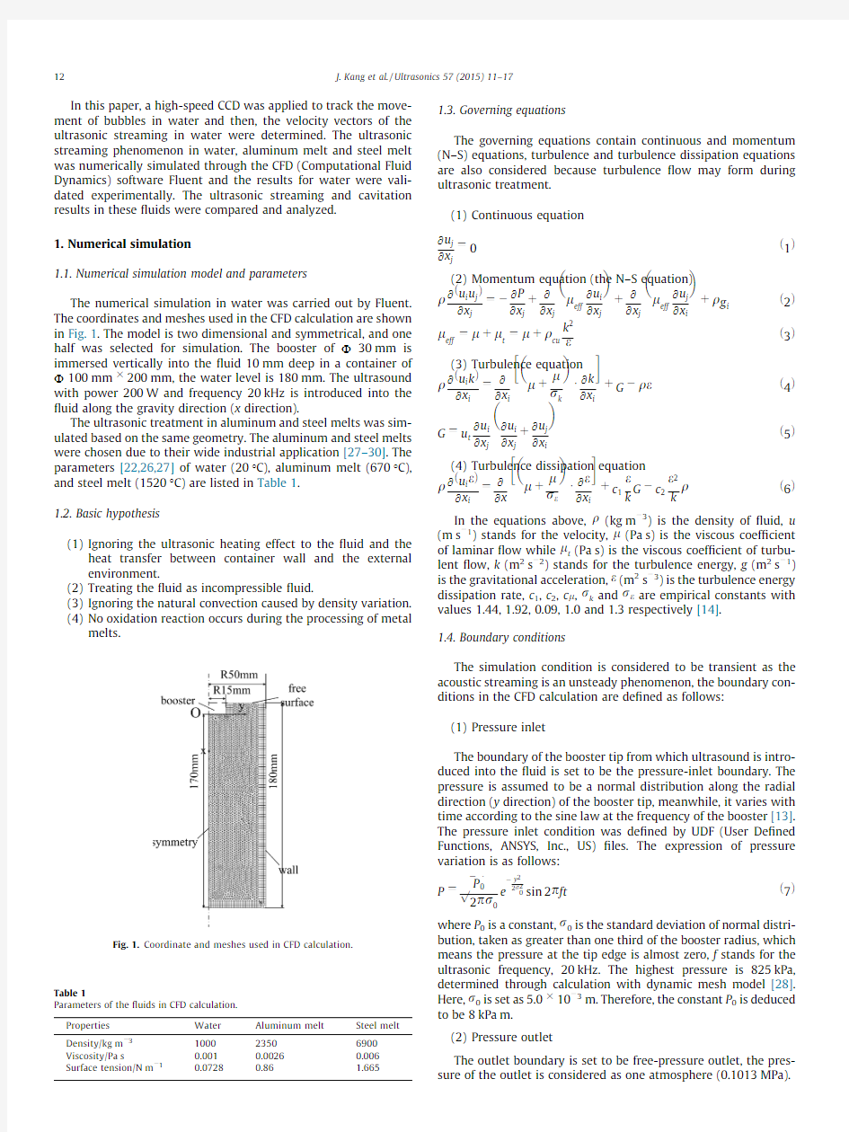
The numerical simulation in water was carried out by Fluent. The coordinates and meshes used in the CFD calculation are shown in Fig.1.The model is two dimensional and symmetrical,and one half was selected for simulation.The booster of U30mm is immersed vertically into the?uid10mm deep in a container of U100mm?200mm,the water level is180mm.The ultrasound with power200W and frequency20kHz is introduced into the ?uid along the gravity direction(x direction).
The ultrasonic treatment in aluminum and steel melts was sim-ulated based on the same geometry.The aluminum and steel melts were chosen due to their wide industrial application[27–30].The parameters[22,26,27]of water(20°C),aluminum melt(670°C), and steel melt(1520°C)are listed in Table1.
1.2.Basic hypothesis
(1)Ignoring the ultrasonic heating effect to the?uid and the https://www.doczj.com/doc/065685081.html,erning equations
The governing equations contain continuous and momentum (N–S)equations,turbulence and turbulence dissipation equations are also considered because turbulence?ow may form during ultrasonic treatment.
(1)Continuous equation
@u j
@x j
?0e1T
(2)Momentum equation(the N–S equation)
q@eu i u jT
j
?à
@P
j
t
@
j
l
eff
@u i
j
t
@
j
l
eff
@u j
i
tq g ie2T
l
eff
?ltl t?ltq cu k
2
ee3T
(3)Turbulence equation
q@eu i kT
@x i
?
@
@x i
lt
l
r
k
á
@k
@x i
tGàq ee4TG?u t
@u i
j
@u i
j
t
@u j
i
e5T
(4)Turbulence dissipation equation
q@eu i
eT
i
?
@l
t
l
r e
á
@e
i
tc1
e
Gàc2
e2
qe6T
In the equations above,q(kg mà3)is the density of?uid,u (m sà1)stands for the velocity,l(Pa s)is the viscous coef?cient of laminar?ow while l t(Pa s)is the viscous coef?cient of turbu-lent?ow,k(m2sà2)stands for the turbulence energy,g(m2sà1) is the gravitational acceleration,e(m2sà3)is the turbulence energy dissipation rate,c1,c2,c l,r k and r e are empirical constants with values1.44,1.92,0.09,1.0and1.3respectively[14].
1.4.Boundary conditions
The simulation condition is considered to be transient as the acoustic streaming is an unsteady phenomenon,the boundary con-ditions in the CFD calculation are de?ned as follows:
(1)Pressure inlet
The boundary of the booster tip from which ultrasound is intro-duced into the?uid is set to be the pressure-inlet boundary.The pressure is assumed to be a normal distribution along the radial direction(y direction)of the booster tip,meanwhile,it varies with time according to the sine law at the frequency of the booster[13]. The pressure inlet condition was de?ned by UDF(User De?ned Functions,ANSYS,Inc.,US)?les.The expression of pressure variation is as follows:
P?
P0
???????
2p
p
r0e
ày
2
2r2
0sin2p fte7T
where P0is a constant,r0is the standard deviation of normal distri-bution,taken as greater than one third of the booster radius,which means the pressure at the tip edge is almost zero,f stands for the ultrasonic frequency,20kHz.The highest pressure is825kPa, determined through calculation with dynamic mesh model[28]. Here,r0is set as5.0?10à3m.Therefore,the constant P0is deduced to be8kPa m.
(2)Pressure outlet
The outlet boundary is set to be free-pressure outlet,the pres-sure of the outlet is considered as one atmosphere(0.1013MPa).
Coordinate and meshes used in CFD calculation.
Table1
Parameters of the?uids in CFD calculation.
Properties Water Aluminum melt Steel melt
Density/kg mà3100023506900
Viscosity/Pa s0.0010.00260.006
Surface tension/N mà10.07280.86 1.665
12J.Kang et al./Ultrasonics57(2015)11–17
(3)Wall boundary
The boundaries except pressure-inlet,pressure-outlet and sym-metry axis are set to be wall boundary,and the heat transfer between wall boundary and environment is ignored.
2.Simulation results and analysis
2.1.Simulation results of streaming velocity
The velocity distribution in these three kinds of?uids water, aluminum melt and steel melt was obtained through numerical simulation,as shown in Fig.2,their attenuation of streaming veloc-ity is different.The streaming velocity along the center-line of the booster decreases to zero at x=140mm(4.67times of the boos-ter’s diameter)in water,at x=78mm(2.6times of the booster’s diameter)in aluminum melt and at x=45mm(1.5times of the booster’s diameter)in steel melt,respectively.In water and alumi-num melt,the maximum velocity does not appear in the area exactly adjacent to the booster’s tip surface,but in the position which is about20mm below the booster,the?uid is accelerated for a while by the resultant force of sonic pressure,gravity,and vis-cous force;as the melt?ows downward,the resultant force of sonic pressure and gravity becomes lower than the viscosity effect, thus,the velocity begins to decrease.In steel melt,the velocity reaches the maximum value just at the booster’s end surface,the reason is that its viscosity is relatively high,the resultant force of sonic pressure and gravity is always lower than viscosity.It is con-cluded that viscosity plays an important role in the distribution of velocity.Some researchers[30]also found that the effect of ultra-sonic treatment in metal melts began to decrease during solidi?ca-along the depth direction(x direction)?rstly increases and then decreases;the distribution of streaming velocity is the most special in steel melt,when y=0,15mm and20mm,the streaming veloc-ity along the depth direction(x direction)decreases from the beginning,only in the position near the side wall of the booster the streaming velocity?rstly increases and then decreases.At the same position of the container,the highest velocity is1.6m/s in water,0.8m/s in aluminum melt and0.3m/s in steel melt,respec-tively.The highest streaming velocity in aluminum melt is nearly three times of that in steel melt,as a result,it is more helpful for mass particles to be scattered in aluminum melt,the effect of ultra-sonic treatment for aluminum melt is better than steel melt.
2.2.Simulation results of streamline
The streamline in the?uid is illustrated in Fig.4,they are obvi-ous different in these three kinds of?uids.Both in water and alu-minum melt,a symmetrical vortex forms due to the drive of downward ultrasonic streaming caused by the booster tip;how-ever,a double-vortex structure,including a vortex in the upper part and a vortex with reverse cycling in the lower part appears in steel melt.It is considered that the viscosity of?uid increases evidently due to the effect of velocity boundary layer when the ?uid is close to the wall,the?uid cannot?ow upward under the sonic pressure due to the effect of gravity and viscosity,instead, it?ows downward.The vortex?owing in reverse direction may trap inclusions and bubbles in the lower part of container,as a result,they cannot be effectively removed.Signi?cant differences can be seen between the appearance of streamline in aluminum melt and steel melt,the factors impacting the streamline are their differences in viscosity and density,as the viscosity and density of melt increase,the vortex tends to?ow downward.
Fig.2.Velocity distribution in three kinds of?uid.
J.Kang et al./Ultrasonics57(2015)11–1713
where P0is1atm(0.1013MPa),P v(MPa)stands for the saturation vapor pressure,r(N/m)is the surface tension coef?cient.The nuclei radius of the dissolved air in the melt is assumed to be R0=10l m, which is closely related to the air content in the liquid,the surface tension coef?cient of water,aluminum melt and
0.0728N/m,0.86N/m and1.665N/m[27]respectively.
sponding cavitation threshold in water,aluminum
melt is0.1034MPa,0.1538MPa and0.2135MPa respectively
on Eq.(8).The cavitation area is mainly related to
threshold,while its intensity is mainly related to
air dissolved in the melt[29].Cavitation is determined
pressure in the?uid,the simulated results of negative
illustrated in Fig.5,the area between the boundary
cavitation area.It is revealed that the cavitation area
water,the second largest in aluminum melt,and
steel melt,locating30mm,20mm and10mm deep
minum melt and steel melt,respectively.The relationship
the bubble’s initial radius and cavitation threshold
kinds of?uid is given in Fig.6,from which it can be
the bubble’s initial radius is the same,the cavitation
highest in steel melt,the second highest in aluminum
lowest in water.Cavitation is more dif?cult to occur
only when the radius of cavitation bubble is larger
cavitation occur;cavitation is easier to occur in
with the critical bubble’s radius0.5l m.The cavitation
in aluminum melt is lower than that in steel melt for
tial radius of bubbles,in this way,the effect of ultrasonic
of aluminum melt is better than that of steel melt.
3.Experimental validation
The ultrasound device(including ultrasound generator and out-put terminal),whose frequency was20kHz and power was adjust-able in the range of0–600W,is shown in Fig.7.The vibration of the ultrasound generator was ampli?ed through the transducer
Fig.3.Flowing velocity in three kinds of?uid(a)y=0,(b)y=15mm,(c)y=20mm. Fig.4.Streamline in three kinds of?uid.
generate ultrasound,?nally ultrasound was introduced into the medium through the booster.In this experiment,ultrasound was introduced into water in a glass container with size U 100mm?200mm,the booster was immersed in water10mm deep,the power of ultrasound generator was200W.The diameter the booster was30mm,the water level in the container was 180mm.A high-speed CCD snapping system was utilized to record the?uid?ow.Numbers of observing points in the?ow?eld were selected to calculate the displacements of bubbles by a series of recorded frames,as a result,the velocity vectors of each bubble were determined to reveal the appearance of streamline in the
?eld.The?ow?eld recorded by the high-speed CCD system shown in Fig.8,from which it can be seen that there was intense turbulence along the center-line below the booster’s tip.
As the?ow?eld was symmetric,34typical points roughly formly distributed in the right side were selected as the observing points,as illustrated in Fig.9(b).Each observing point has a
and an end location,the former location stands for the position where the observing point lies in the?rst frame of video record-ing,and the latter one was the location of the observing point
Fig.5.Distribution of negative pressure in water,aluminum melt and steel melt.
Fig.6.Relationship between the bubble nuclei radius and cavitation threshold.
Fig.7.Ultrasound device(a)UGH ultrasound control panel(b)ultrasonic booster.Fig.8.Flow?eld pictured by high-speed CCD system.
the last frame of video recording.The velocity vector of each observing point was obtained through the calculation based on its start and end positions and the time differences between
frames,the results are listed in the
of the whole?ow?eld is plot in
in water obtained by numerical simu-
(a),from which it can be seen that
<20mm is the highest,it is helpful
and simulation results in this area.
direction(x direction)at the locations
mm were selected for study,the veloc-
measured using high-speed CCD system,the comparison of velocity in experiment and simulation is shown in Fig.10.
The velocity in experiment is approximate to that in simulation, but the experiment results are slightly
results,as the ultrasonic energy
increased the water temperature,leading
viscosity.When the water temperature
40°C,the viscosity decreased
0.6560?10à3Pa s[31],as a result,
increased.However,the heating effect
ignored in simulation,the viscosity of
constant,in this way,the velocity in experiment
in simulation.The variation trends of
https://www.doczj.com/doc/065685081.html,parison of streamline in experiment and simulation. https://www.doczj.com/doc/065685081.html,parison of velocity in experiment and simulation.
simulation are similar,indicating that numerical simulation reveals the ultrasonic streaming correctly.
The comparison of the streamline obtained in experiment and simulation is illustrated in Fig.9,it can be seen that the simulated streamline is in agreement with the experimental one.
4.Conclusions
(1)The ultrasonic streaming in water was investigated by CFD
numerical simulation,and the results were validated by experiments.The simulated streaming velocities and streamlines are consistent with that observed in experiment.
(2)The ultrasonic streaming phenomenon in aluminum melt
and steel melt was studied by numerical simulation as well, the streaming phenomena is different in those two melts, the streaming velocity in aluminum melt is higher than that in steel melt at the same position.A symmetrical vortex forms both in water and aluminum melt due to the drive of downward ultrasonic streaming caused by the booster tip;however,a double-vortex structure,including a vortex in the upper part and a vortex with reverse cycling in the lower part appears in steel melt,as a result,the inclusions and air bubbles may be trapped in the lower part of con-tainer.The factors mainly affecting the ultrasonic streaming are the density and viscosity of?uids,the streaming velocity decreases with their increase,downward vortex tends to form as they increase to a certain degree,leading to inclu-sions and bubbles being trapped,as a result,the effect of ultrasonic treatment is greatly deducted.
(3)The cavitation area in aluminum melt is larger than that in
steel melt,the cavitation threshold in aluminum melt is lower than that in steel melt with the same initial radius of the bubbles.It is easier for cavitation to occur in alumi-num melt,the effect of ultrasonic treatment of aluminum melt is better than that of steel melt.
Acknowledgement
This research was supported by National Natural Science Foundation of China(No.51075299).
References
[1]G.I.Eskin,Principles of ultrasonic treatment application for light alloys melts,
Adv.Perform Mater.4(1997)223.
[2]G.I.Eskin,Broad prospects for commercial application of the ultrasonic
(cavitation)melt treatment of light alloys,Ultrason.Sonochem.8(3)(2001) 319.
[3]J.A.Cosgrove,J.M.Buick,S.D.Pye,et al.,PIV applied to Eckart streaming
produced by a medical ultrasound transducer,Ultrasonics39(2001)46. [4]V.Frenkel,R.Gurka,A.Liberzon,et al.,Preliminary investigations of ultrasound
induced acoustic streaming using particle image velocimetry,Ultrasonics39 (2001)153.
[5]K.D.Frampton,K.Minor,S.Martin,Acoustic streaming in micro-scale
cylindrical channels,Appl.Acoust.65(2004)1121.
[6]Y.Han,K.Li,J.Wang,et al.,In?uence of high-intensity ultrasound on grain
re?ning performance of Al–5Ti–1B master alloy on aluminum,Mater.Sci.Eng.
A405(2005)306.
[7]X.Jian,H.Xu,T.T.Meek,et al.,Effect of power ultrasound on solidi?cation of
aluminum A356alloy,Mater.Lett.59(2)(2005)190.
[8]A.Kumar,T.Kumaresan,A.B.Pandit,et al.,Characterization of?ow phenomena
induced by ultrasonic horn,Chem.Eng.Sci.61(2006)7410.
[9]G.Madelin,D.Grucker,J.M.Franconi,et al.,Magnetic resonance imaging of
acoustic streaming:absorption coef?cient and acoustic?eld shape estimation, Ultrasonics44(2006)272.
[10]Y.L.Li,H.K.Feng,F.R.Cao,et al.,Effect of high density ultrasonic on the
microstructure and re?ning property of Al–5Ti–0.25C grain re?ner alloy, Mater.Sci.Eng.A487(2)(2008)518.
[11]X.Liu,Y.Osawa,S.Takamori,et al.,Microstructure and mechanical properties
of AZ91alloy produced with ultrasonic vibration,Mater.Sci.Eng.A487(1) (2008)120.
[12]Xiaoming Zhang,Tingjie Zhang,Feng Tian,The effect of multi-direction forging
on the property improvement of7075aluminum alloys,Rare Met.Mater.Eng.
32(5)(2003)372.
[13]Taibao Li,Computational Accoustic:The Accoustic Field Equation and
Computation Method,Science Press,Beijing,2005.
[14]Enhua Xie,Xiaoqian Li,The phenomenon of accoustic streaming in the
processing of ultrasonic treatment of melt,J.Beijing Sci.Technol.Univ.31 (2009)1426.
[15]Andrzej Nowicki,Tomasz Kowalewski,Wojciech Secomski,Janusz Wo′jcik,
Estimation of acoustical streaming:theoretical model,Doppler measurements and optical visualization,Eur.J.Ultrasound7(1998)73–81.
[16]Qin Dai,Run-jie Wei,Zhan Huang,Gong-xin Shen,Experimental Study of
Supersonic Jet Flow Using DPIV,J.Beijing Univ.Aeronaut.Astronaut.27(6) (2001)666–669.
[17]J.A.Cosgrove,J.M.Buick,S.D.Pye,C.A.Greated,PIV applied to Eckart streaming
produced by a medical ultrasound transducer,Ultrasonics39(2001)461–464.
[18]Yao Zhao Hui,Hou Xiu Zhou,Hao Peng Fei,PIV experimental research on
supersonic impinging jet,J.Exp.Fluid Mech.21(2007)32–35.
[19]Peng Yumin,Wang Heng,Preparing high purity vanadium ingots by electron
beam cold-hearth furnace,Baoshan Iron Steel Technol.5(2012)17–28. [20]Wenlin Xu,Yufang He,Yaqiong Wang,Solving of motion equation and
simulation of the moving process of ultrasonic cavitation bubble,J.Yangzhou Univ.Nat.Sci.Ed.8(2005)55–59.
[21]Li Zhengcai,Lin Shuyu,Numerical simulation of the factors in?uencing
ultrasonic cavitation,J.Shanxi Normal Univ.Nat.Sci.Ed.36(2008)38–42. [22]Wei Kong,Daqiang Cang,Wenbo Wang,Simulation of moving process of
cavitation bubbles in the steel melt,Sci.Technol.Eng.10(2010)8696–8701.
[23]Wei Kong,Daqiang Cang,Wenbo Wang,Numerical simulation of
macroscopical characteristic of ultrasonic cavitation in steel melt,Comput.
Appl.15(2010)49–53.
[24]Rongguang Liu,Xiaoqian Li,Shicheng Hu,Process simulation of ultrasonic
generated cavitation effect in aluminum alloy fusant and the evolution process of air bubble,Dev.Res.09(2007)16–19.
[25]Liyan Liu,Yang Yang,Penghong Liu,Wei Tan,The in?uence of air content in
water on ultrasonic cavitation?eld,Ultrason.Sonochem.21(2014)566–571.
[26]Yunmeng Yang,Shicheng Hu,Yongqing Hu,Mingzhi Fu,Yong Mao,Ping Zhang,
Numerical simulation of the cavitation bubbles collapsing process in aluminum melt29(2009)417–420.
[27]Jinwu Kang,Xiaopeng Zhang,Yisen Hu,Jiyuma,Yongyi Hu,Tianyou Huang,
Ultrasonic treatment of the304stainless steel melt,ISIJ Int.54(2014) 281–287.
[28]Jinwu Kang,Yisen Hu,Jiyu Ma,Tianyou Huang,Effect of different air content
on cavitation with ultrasonic treatment,in:3rd International Conference on Advances in Materials and Manufacturing Processes,2013,pp.43–7.
[29]Hu Shicheng,Xia Chenxi,Shao Gaojian,Guan Furu,Numerical simulation of
ultrasonic streams in pure aluminum melts,Foundry Technol.31(2010) 1609–1613.
[30]Xie En-hua,Li Xiao-qian,Acoustic streaming phenomenon during ultrasonic
sonication on melt,J.Univ.Sci.Technol.Beijing31(2009)1425–1429. [31]Peng Hu,Zeshao Chen,Calorimetry Technology and Thermal Properties
Determination,Press of University of Science and Technology of China,2009, p.12.
J.Kang et al./Ultrasonics57(2015)11–1717