A30-Frames/s Megapixel Real-Time
CMOS Image Processor
Daniel Doswald,Member,IEEE,Jürg H?fliger,Patrick Blessing,Norbert Felber,Peter Niederer,and
Wolfgang Fichtner,Fellow,IEEE
Abstract—A real-time1024
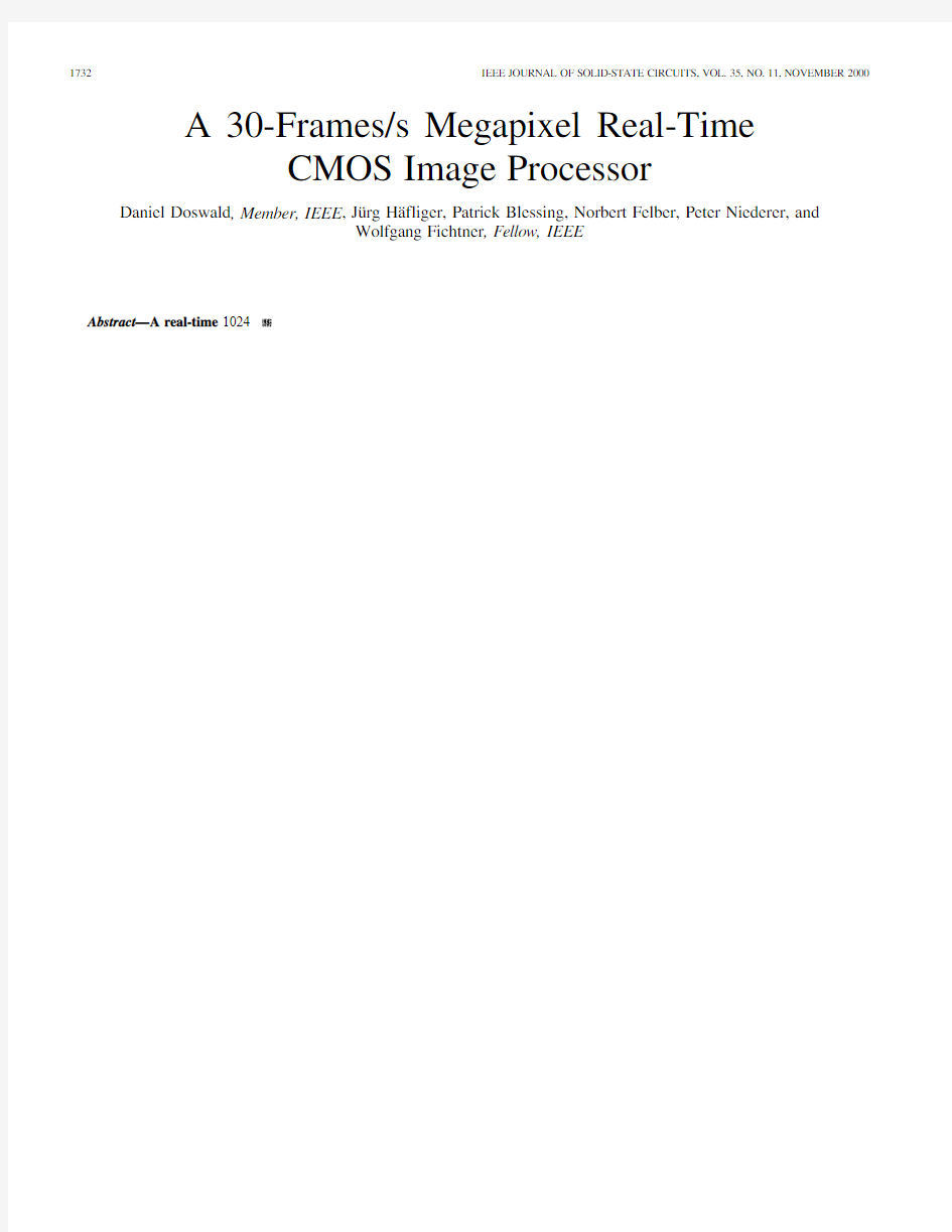
Fig.2.Block diagram of prototype camera system with image
processor.
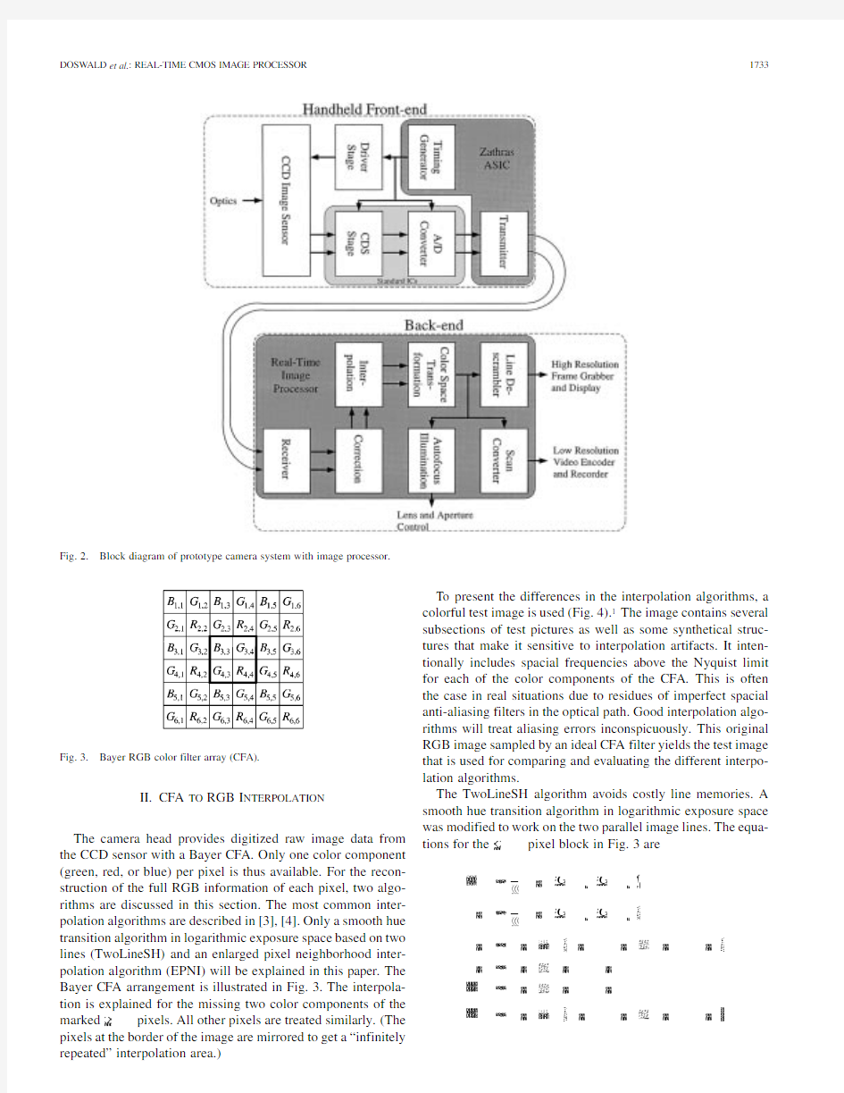
Fig.3.Bayer RGB color filter array (CFA).
II.CFA TO RGB I NTERPOLATION
The camera head provides digitized raw image data from the CCD sensor with a Bayer CFA.Only one color component (green,red,or blue)per pixel is thus available.For the recon-struction of the full RGB information of each pixel,two algo-rithms are discussed in this section.The most common inter-polation algorithms are described in [3],[4].Only a smooth hue transition algorithm in logarithmic exposure space based on two lines (TwoLineSH)and an enlarged pixel neighborhood inter-polation algorithm (EPNI)will be explained in this paper.The Bayer CFA arrangement is illustrated in Fig.3.The interpola-tion is explained for the missing two color components of the
marked
pixels.All other pixels are treated similarly.(The pixels at the border of the image are mirrored to get a “infinitely repeated”interpolation area.)
To present the differences in the interpolation algorithms,a colorful test image is used (Fig.4).1The image contains several subsections of test pictures as well as some synthetical struc-tures that make it sensitive to interpolation artifacts.It inten-tionally includes spacial frequencies above the Nyquist limit for each of the color components of the CFA.This is often the case in real situations due to residues of imperfect spacial anti-aliasing filters in the optical path.Good interpolation algo-rithms will treat aliasing errors inconspicuously.This original RGB image sampled by an ideal CFA filter yields the test image that is used for comparing and evaluating the different interpo-lation algorithms.
The TwoLineSH algorithm avoids costly line memories.A smooth hue transition algorithm in logarithmic exposure space was modified to work on the two parallel image lines.The equa-tions for
the
pixel block in Fig.3
are
Fig.4.Test image used for interpolation studies(color image available for download:http://www.iis.ee.ethz.ch/publications/papers/2000/JSSC-35-11-fig4.tif).
Fig.5.Interpolated image using the TwoLineSH algorithm(color image available for download:http://www.iis.ee.ethz.ch/publications/papers/2000/JSSC-
35-11-fig5.tif).
(2)(4)
Fig.6.Adaptive green interpolation using an enlarged neighborhood.
Fig.7.Interpolated image using EPNI algorithm(color image available:http://www.iis.ee.ethz.ch/publications/papers/2000/JSSC-35-11-fig7.tif).
is either the red or blue value at location and
corresponds to averaging the four neighbor pixels
and
of30(range).To interpolate a green value of an
image line,five lines are used.For the chrominance interpola-
tion,the green values of two more adjacent-lines pixels need to
be known.This means that a total of seven lines are accessed to
reconstruct a red or blue pixel value.
III.C OLOR S PACE T RANSFORMATION
The CCD sensor of the camera and the display device(e.g., cathode ray tube monitor(CRT)or flat panel)use different de-vice-dependent RGB color spaces.For correct display and inter-pretation of the images,an accurate conversion between those two color spaces must be found.
Color space transformation can be divided into three cate-gories.The first approach is a linear regression method which optimizes the correlation between the color spaces.The second category divides the source color space into small cells and uses a three-dimensional lookup table and interpolation to calculate the target color specifications.The third variant is based on cog-nitive methods such as fuzzy logic and neural networks which try to simulate human decision-making processes.
Due to the higher implementation cost of the latter two cate-gories,the linear regression method was implemented.For this approach,the color space transformation can be written as fol-
lows:
(8)
Extensive simulations were performed to find which of these
polynomals provide sufficient accuracy.In this context,the fol-
lowing procedure was performed:
1)Reflectance spectra of different color patches under stan-
dard D65illumination(Commission Internationale de
L’éclairage,CIE)define the reference emission spectra.
2)The CIE1931standard colorimetric observer[7]ap-
plied to the reference emission spectra provides
the
response of the reference emission spectra.
3)The
calculated
values are transformed to
yield the
new
values and the spectral emittance of the
three phosphors of a typical6500-K balanced CRT mon-
itor[8]are used to derive the additive emission spectra
for the color patches as produced by the monitor.
6)
and
,the measure for accuracy.
8)The polynomial coefficients are now optimized in order
to minimize the resulting average error.
Table I shows the resulting errors for color patches of a Gre-
tagMacbeth?ColorChecker?(GMCC)[9],various Munsell
color chips(MCC)[10],and ceramic color tiles(CCS)from
CERAM Research[11].
According to these results,six polynomial terms offer a
good trade-off between accuracy and implementation costs.
The color space transformation can therefore be expressed by
the following matrix equation,whereas the
matrix
:
(9)
In Fig.8,the locations of the color patches of a GMCC in the
CIELAB color space are shown.The crosses indicate the refer-
ence values and the circles correspond to transformed values.
The solid border line indicates the gamut of the sensor-filter
combination.
The color space transformation is implemented with pro-
grammable coefficients.The programming range has been op-
timized per coefficient based on simulations of different scene
illuminations.
IV.A UTOFOCUS
State-of-the-art passive autofocus strategies as routinely in-
stalled in video cameras[12]are based on single TV lines.They
are often too slow for real-time implementations,e.g.,as in med-
ical endoscopes,and show unreliable performance for mainly
horizontally structured objects.A new passive autofocus crite-
rion[13]based on two-dimensional regions solves these prob-
lems.
Fig.8.Result of623matrix color space transformation:2indicates reference value, corresponds to transformed value.
Focusing on an object can be achieved by maximizing the high-frequency content of its image.Therefore,a focus criterion has to provide a scalar measure of the high-frequency content which yields a maximum value when the object is in focus. Various strategies for deriving a focus criterion can be found in the literature[14]–[17].The most well known are the varia-tion of intensity,sum modulus difference(SMD),spectrum of power(SP),and entropy of grey levels.
SMD adapted to a discrete image is well suited to hardware
implementation since only additions/subtractions are required.
(14)
Fig.11.Block diagram of the
ASIC.
Fig.12.Architecture of correction unit.
For low-voltage differential signaling (LVDS)standard conforming data transmission from the camera head,special full-custom level-and impedance-compatible receivers were designed.These receivers are also used for the 200-MHz system clock input.Although the measured nonreturn-to-zero (NRZ)data rate limit which exceeds 700Mb/s would allow a single 400-Mb/s data channel,transmitter and cable specifications let us decide to implement two 200-Mb/s channels.
CCD sensors are divided into different grade classes de-pending on the number of minor and major defective https://www.doczj.com/doc/035320965.html,ing a pixelwise gain and dark current compensation,sensors with minor defects perform the same as sensors without any defects.
Besides minor pixel defects,the different light sensitivity of each color may degrade image quality.Therefore,even with high-grade CCD sensors,at least the gain of each color has to be adjusted.The correction algorithm chosen can be described with the following
equation:
(16)
The architecture of the integrated correction unit is illustrated in Fig.12.The two lines are multiplexed together and alter-natingly pixelwise processed by common arithmetic sub-blocks using double-edge triggered (DET)design technique.At the end
Fig.13.Architecture of SDRAM and configuration
interfaces.
Fig.14.CFA pixels used for interpolation.
of this unit,the two lines are demultiplexed for further par-allel processing by the interpolation unit.The pre-gain values are taken directly from the on-chip register file and the offset and gain values come from the correction SDRAM interface.The correction unit performs 80million multiply–accumulate (MAC)operations each second.
The external 64-Mb RAM for dark current and white gain compensation holds four programmable correction sets.This enables buffering and therefore allows loading and switching during operation without loss of frames.In addition to the pixelwise correction,a second mode without external memory is implemented.It corrects the CCD data of each color channel globally.The SDRAM interface for this unit is depicted in Fig.13.Depending on the programmed mode,the correction data is taken from the register file (colorwise)or from an external SDRAM (pixelwise).Sixteen bits of data are required each 40-MHz cycle.This gives a required continuous band-width of 80MB/s.To guarantee this bandwidth,a single-edge triggered (SET)100-MHz 8-b SDRAM interface was imple-mented.Depending on the phase relation between the 100-MHz SET and the 20-MHz DET clock domain of the surrounding blocks,the data and control signals are read into or written out of the interface.
Since the EPNI interpolation algorithm was chosen and two lines are processed simultaneously,the interpolation unit needs seven lines additional to the two lines coming from the correc-tion unit.Fig.14depicts the seven line-memories connected as a huge first-in-first-out (FIFO)memory with a register chain at each line memory output,which form the actual CFA pixel array used for the interpolation of the two marked center pixels.The architecture of the arithmetic part of the algorithm is shown in Fig.15.First the pixel neighborhood is examined to decide on the direction used for the green interpolation.Then the required green values are calculated.After the green values are known,
Fig.15.Architecture of arithmetic part of interpolation
algorithm.
Fig.16.Architecture of color space transformation.
the red and blue values of the pixels being interpolated are cal-culated using three smooth-hue transition interpolators which work in the logarithmic exposure space.Finally,the RGB values of each pixel are selected and output.The required memory bandwidth of this interpolation algorithm is 700MB/s and a total of 580million operations/s (not including round and shift operations)are calculated by the interpolation unit.
The color space transformation unit performs the previously
described
matrix transformation.Its architecture is pre-sented in Fig.16.First
the
,
and terms are cal-culated.Then the complete six-dimensional vector is given into three equal sub-blocks (one for each color component)which perform the actual transformation.Here again,only one trans-formation unit was implemented for both lines together using the same DET clocking scheme as the correction unit.The color
space transformation unit performs 240million signed multipli-cations and 600million signed MACs each second.
The autofocus and illumination control unit calculates a re-duced resolution luminance image and over a programmable window the SPSMD focus criterion.The architecture of this focus and illumination unit is presented in Fig.17.
The luminance information of each pixel is first calculated according to
(17).
Fig.17.Architecture of focus and illumination
unit.
Fig.18.Architecture of scan converter unit.
frame.The focus and illumination unit has a 20-MHz DET clock domain and performs 230million operations each second.Another feature of this ASIC is the scan converter.An SDRAM as temporary frame memory and a PAL video encoder IC are the only external components required.Fig.18illustrates the architecture of this unit.Simultaneous write and read operations for the frame buffering of the scan converter require a complex scheduling solution.The decimated progressive scan images are stored in the external memory with a rate of 30frames/s and read back in an interlaced frame format with 50fields/s.On-chip FIFO memories couple the 10-MHz 24-b input pixel stream to the 100-MHz clocked SDRAM control unit,and synchronize the digital image data to the 14.75-MHz domain of the external video encoder IC.
The whole functionality of this multifunction ASIC is not used in each application.In order to save power and to reduce
noise in the back-end when certain blocks are not in use,each block has its own clock distribution network which can be shut down by clock gating.All clocks inside of the ASIC are derived from a 100-MHz clock with a duty cycle of 50%,and the video encoder clock of 14.75MHz.
VI.D ESIGN M ETHODOLOGY AND R EALIZATION
The IC contains RAMs,LVDS receivers,and standard cell blocks.The full-custom layout LVDS receivers are provided with isolated power supplies from individual package pins.The standard cell blocks use an HDL/synthesis methodology.Synthesis was performed with Synopsys.A cycle-true C description of the ASIC was built for verification purposes and test vector generation.Timing-driven layout is used for cell placement and routing.Chip floor planning and assembly
Fig.19.Die micrograph with enlarged LVDS receiver.
TABLE II C HIP O
VERVIEW
are done with the Silicon Ensemble toolset by https://www.doczj.com/doc/035320965.html,mercial design and electrical rule checking (DRC,ERC),and layout versus schematic (LVS)tools are used for physical verification.Built-in self-test structures for the RAM macro cells,partial scan paths,and a configurable test port ensure testability.
A total of eleven clock domains,partly in DET design tech-nique,have been implemented.They carry three phase-locked and one asynchronous clocks.Domain-wise clock gating allows to reduce power if some functionality of the ASIC is unused.The datapath has been optimized concerning word widths.The ASIC is fully operational at 30frames/s with a supply voltage ranging from 2.5to 3.3V .For the power measurements,real video images were used and all clock domains were active.Due to the lack of 2.5-V 64-Mb SDRAMs,the colorwise correction mode was used for the 2.5-V power measurements and the scan
converter was operational with dummy data.Fig.19shows a die photograph of the ASIC.The chip features are summarized in Table II.
VII.C ONCLUSION
A digital 30-frames/s megapixel real-time CMOS image pro-cessor ASIC has been implemented.By its complex interpo-lation algorithm,
the
matrix color space transformation,and the enhanced autofocus criterion calculation,it improves the system performance of 1-CCD color motion cameras.The pixelwise correction of CCD imperfections such as dark current and white gain even allows the use of lower-grade CCD sensors,which reduces system cost.
The ASIC performs 1790million operations each second,not including the round and shift operations.The maximum word width is 38bits.The total memory bandwidth including all internal and external RAMs is 1620MB/s.Implemented in a
0.35-.
This image processor with its algorithms could also be used to improve quality of today’s CMOS image sensors.Especially the pixelwise correction mode would help to scale down some of the disadvantages of CMOS image sensors.Furthermore,im-plementing these algorithms together with a CMOS sensor on one chip would result in an improved camera-on-a-chip solu-tion.
A CKNOWLEDGMENT
The authors wish to thank S.Oetiker and B.Schreier for their excellent work during the design of this ASIC,and M.Br?ndli,A.Burg,J.Hertle,R.Reutemann,and Y .Lehareinger for their essential contributions making possible this successful design.
R EFERENCES
[1]H.Zen et al.,“A new digital signal processor for progressive scan CCD,”
IEEE Trans.Consumer Electron.,vol.44,pp.289–296,May 1998.[2]M.Loinaz et al.,“A 200mW 3.3V CMOS color camera IC producing
352228824b video at 30frames/s,”in Dig.Tech.Papers,IEEE Int.Solid-State Circuits Conf.,1998,pp.168–169.
[3]J.E.Adams Jr.,“Interactions between color plane interpolation and other
image processing functions in electronic photography,”in SPIE—Cam-eras and Systems for Electronic Photography and Scientific Imaging ,vol.2416,Bellingham,W A,Feb.1995,pp.144–151.[4],“Design of practical color filter array interpolation algorithms
for digital cameras,”in SPIE—Real-Time Imaging II ,vol.3028,Bellingham,W A,Feb.1997,pp.117–125.
[5]“KAI-1010Series—Performance Specifications,”Eastman Kodak Co.,
1998.
[6]“Near-Infrared Blocking Filter,”Balzers Thin Films,BD 800110RE
(0699-1),1999.
[7]“Colorimetry,”Comission Internationale de L’éclairage (CIE),Vienna,
Austria,2nd ed.,Pub.CIE 15.2,1986.
[8] D.B.Judd,Color in Business,Science and Industry .New York:Wiley,
1975.
[9] C.S.McCamy et al.,“A color-rendition chart,”J.Appl.Photographic
Eng.,vol.2,no.3,pp.95–99,1976.
[10]“Munsell book of color—Matte finish collection,”Munsell Color,Bal-timore,MD,pt.40291,1976.
[11]“Ceramic Color Standards Series II,”CERAM Research,Ltd.,Stafford-shire,U.K.,1990.
[12]NV-S700Training Manual ,no.VRD9205D101,Panasonic.
[13]P.Blessing et al.,“Passive autofocus for digital endoscopic imaging sys-tems,”in SPIE—Biomedical Diagnostic,Guidance,and Surgical-Assist Systems ,1999,vol.3595,pp.148–157.
[14] B.Liao,“A Study of Camera Focusing in Different Applications,”Ph.D.
dissertation,Hamburg,Germany,1993.(in German).
[15]R.A.Jarvis,“Focus optimization criteria for computer image pro-cessing,”Microscope ,1976.
[16] E.P.Krotov,Active Computer Vision by Cooperative Focus and
Stereo .New York:Springer,1989.
[17]K.Ooi et al.,“An advanced autofocus system for video camera using
quasi-condition reasoning,”IEEE Consumer Electron.,vol.36,Feb.
1990.
Daniel Doswald (M’00)was born in Zürich,Switzerland,in 1971.He received the Dipl.El.-Ing.(M.Sc.)and Dr.sc.techn.(Ph.D.)degrees in elec-tronic engineering from the Swiss Federal Institute of Technology (ETH),Zürich,in 1996and 2000,respectively.
He joined the Integrated Systems Laboratory (IIS)of ETH,where he worked as a Research and Teaching Assistant in the field of ASIC and system design and test.His research interests are in digital signal pro-cessing and mixed signal circuits with applications
to image processing,digital audio/video,and system-oriented VLSI design.
Jürg H?fliger was born in Baden,Switzerland,in 1971.He received the Dipl.El.-Ing.(M.Sc.)degree in electronic engineering from the Swiss Federal Insti-tute of Technology (ETH),Zürich,Switzerland,in 1997.
He joined the Institute of Biomedical Engineering and Medical Informatics of the ETH,working in the area of high-definition television systems and color
science.
Patrick Blessing was born in Menzikon,Switzer-land,in 1970.He received the Dipl.Masch.-Ing.(M.Sc.)and Dr.sc.techn.(Ph.D.)degrees in mechanical engineering from the Swiss Federal Institute of Technology (ETH),Zürich,Switzerland,in 1996and 2000,respectively.
He joined the Institute of Biomedical Engineering and Medical Informatics of the ETH,working in the fields of digital control of passive focus and illumi-nation
systems.
Norbert Felber was born in Trimbach,Switzerland,in 1951.He received the Dipl.Phys.(M.Sc.)in 1976from the Swiss Federal Institute of Technology (ETH),Zürich,Switzerland.Subsequently,he was a Research Assistant at the Laboratory of Applied Physics,ETH,where he received the Dr.sc.nat.(Ph.D.)degree in 1986.
In 1987,he joined the Integrated Systems Labora-tory (IIS)of ETH,where he is currently a Research Associate and Lecturer in the field of VLSI design and test.His research interests are in telecommunica-tions,digital signal processing (digital filters,audio,video,pattern recognition,and image processing),optoelectronics,measurement techniques,and device
characterization.
Peter Niederer received the degree in theoretical physics at the University of Zürich and the Ph.D.degree at the Swiss Federal Institute of Technology (ETH)Zürich,Switzerland,in 1967and 1972,respectively.
From 1973to 1974,he was a Research Engineer at the Biomedical Department,General Motors Research Laboratories,Warren,MI.He then joined the Institute of Biomedical Engineering,ETH Zürich,as a Senior Researcher.In the spring of 1980,he was a Visiting Faculty Member at the University
of Houston,TX.He has been a Full Professor of Biomedical Engineering at the ETH Zürich since 1992.In the field of medical optics,he has collaborated with industry relating to high-definition endoscopy.He has been a Consultant in the Biomed II program of the EU and is Editor-in-Chief of Technology and Health Care .
Prof.Niederer received the Goetz Prize from the Faculty of Medicine at the University of Zurich for his work on injury biomechanics in
1980.
Wolfgang Fichtner (M’79–SM’84–F’90)received the Dipl.Ing.degree in physics and the Ph.D.degree in electrical engineering from the Technical University of Vienna,Vienna,Austria,in 1974and 1978,respectively.
From 1975to 1978,he was an Assistant Professor in the Department of Electrical Engineering,Tech-nical University of Vienna.From 1979through 1985,he was with AT&T Bell Laboratories,Murray Hill,NJ.Since 1985,he has been Professor and Head of the Integrated Systems Laboratory,Swiss Federal In-stitute of Technology (ETH),Zürich,Switzerland.In 1993,he founded ISE In-tegrated Systems Engineering AG,a company in the field of technology com-puter-aided design.
Prof.Fichtner won the Andy S.Grove Field Award for his work on numer-ical modeling of semiconductor devices in 2000.He is a member of the Swiss National Academy of Engineering.
题目 在线考试系统 1、 实验目的 ①熟练运用JAVA 开发环境及工具、并用JAVA 语言编写程序; ②掌握面向对象的概念; ③掌握系统功能模块的合理划分,并实现各模块接口的连接; ④掌握C/S 结构的编程方法; ⑤设计数据库模型。 2、 实验内容 ①编辑生成试题库,随机生成本次考试试题,同时提供在线评分并保存结果。 ②选择ACCESS 作为后台的数据库。 3、 实验过程 3.1 系统模块部分设计 题库管理:用于对单个试题的增、删、改、查等基本维护,还可对题库进行数据备份和数据还原。我们针对不同题型、不同应用范围及不同科目对试题进行维护。 试卷管理:可进行三种组卷方式的维护:随机组卷、人工组卷、综合组卷。还可对考生的基本信息进行维护。 考试管理:对考试分配试卷,并对考试的基本信息进行维护。相当于人工安排考试的过程 评卷管理:对试卷的客观题分配评卷人,并对评卷人基本信息进行管理。 成绩管理:对每次考试的学生成绩的基本信息进行维护,并提供学生成绩的统计管理。 用户管理:对使用本系统的用户基本信息进行维护,用户多数为:系统管理员、老师、教务处人员、其他 权限管理:对系统的访问权限进行管理,并对用户可进行权限的分配。 系统应该具备的基本功能 各模块需完成以下功能: 在线考试系统 信息管理 评卷管理 试卷管理 题 库管理 成绩管理 考试管理 用户管理 权限管理
题型维护:对试题的题型进行增、删、改、查操作。在操作之后会自动刷新主页,以使信息更新。 范围维护:对试题的应用范围进行增、删、改、查操作。在操作之后会自动刷新主页,以使信息更新。 科目维护:对试题的科目进行增、删、改、查操作。在操作之后会自动刷新主页,以使信息更新。 试题维护:对试题的基本信息进行增、删、改、查操作。在操作之后会自动刷新主页,以使信息更新。 其他维护:对试题信息的批量查询,并可进行数据导出、数据备份、数据恢复。 随机组卷:用户只需对试卷题型进行设置就可组卷的方式。 人工组卷:可使用户选择试卷的题型中的试题的组卷方式。 综合组卷:是随机组卷与人工组卷的混合组卷方式,即用户对某一类型的试题可进行选择,也可对试题不进行选择。 试卷其他维护:对试卷信息的批量查询,对试题的数据备份与还原。 考试信息维护:对考试的时间、地点、监考人、考试用的试卷、试卷总分数及答卷总时间等考试的基本要素进行设置。 考生信息维护:对考试的学生的基本信息进行增、删、改、查操作,在操作之后会自动刷新主页,以使信息更新。 分配评卷人:对考试所用试卷的客观题分配评卷人,并对评卷的基本信息进行维护。 评卷人评卷:对分配试卷的评卷人可以在此进行评卷。 考生成绩维护:对考试的考生成绩信息进行统计与汇总,对有权限的人可进行成 考试管理 考试信息维护 分配评卷人 评卷管理 成绩管理 评卷人评卷 考生信息维护 考生成绩维护 成绩其他维护 题库管理 试卷管理 试卷其他维护 试卷信息维护 其它 维护 试题 维护 基本 维护 综 合组卷 人工组卷 随机组卷 题型维护 科目维护 范围维护
基于JAVAEE的在线考试系统 【内容提要】在线考试系统旨在实现考试的无纸化管理,对一些科目的考试可以通过互联网络或局域网进行,方便校方考务的管理,也方便了考生,尤其适合考生分布广,不易集中的远程教育。我主要开发系统的后台管理系统—JAVA 在线考试管理子系统,它包括试题管理、考生管理、试卷管理、试卷自动审批等功能。本论文主要介绍了对JAVAEE在线考试系统的分析、设计和开发的全部过程。运用ER图,程序流程图等对在线系统的设计过程进行详细的说明。全文共分为开发方案、需求分析、系统设计、关键技术解决,结论五部分。开发方案中主要介绍开发在线考试系统得目的、开发方案的选择及开发框架的技术的确定;需求分析介绍了在线考试系统的总体需求及系统各模块的功能需求;系统设计介绍了系统设计的指导思想、数据库的设计、系统模块的设计;关键技术介绍了在具体实现时需解决的一些技术,如开发框架的整合技术、开发 框架与数据库的连接及数据的备份与还原。 【关键词】:JSP, Servlet, Struts, JAVA,MySQL数据库,B/S模式 On-line examination system base on JAVA
Student : CHAO SUN supervisor: WEI MING XIAO 【ABSTRACT】On-line examination system the aim is carry out examination of have no the paper turn a management, can carry on through Internet net or bureau area net to some examinations of categories, convenient school square test the management of duty, also convenient the examinee is particularly suitable for examinee to distribute widely and not easily concentrated of long range education.I mainly develop the system-JAVAEE of the backstage management's on-line examination management sub- system of system and it includes to try the management, on-line creation of a management, examinee to try book, control the constitution that the student examine and try an examination and approval etc. function.This thesis mainly introduced to manage the analysis, design of the sub- system and all processes of the development to JAVAEE's on-line examination.Make use of ER diagram, procedure flow chart etc. to on-line manage the design process of sub- system to carry on expatiation.The full text is totally divided into the design, key technique of the analysis, system of the development project, need to solve, conclusion five part.Develop the main introduction in the project develops on-line examination system purpose, development project of choice and development frame of the assurance of technique;The need analysis introduced the total need of the on-line examination system and the function request of each mold of system piece;The system design introduced the design, system mold of the instruction thought, database of system design the design of the piece;The key technique introduced at concrete carry out need some techniques for solve, such as development frame of integration technique, development frame with The database link and the backup and revivification of data. Keyword: Servlet ,JSP, JAVA,MySql, Model of B/ S
最全的功率计算公式 概述 ? ? ? ?功率包括电功率、机械功率。电功率又包括直流电功率、交流电功率和射频功率;交流功率又包括正弦电路功率和非正弦电路功率;机械功率又包括线位移功率和角位移功率,角位移功率常见于电机输出功率;电功率还可分为瞬时功率、平均功率(有功功率)、无功功率、视在功率。在电学中,不加特殊声明时,功率均指有功功率。在非正弦电路中,无功功率又可分为位移无功功率,畸变无功功率,两者的方和根称为广义无功功率。 本文列出了上述所有功率计算公式,文中p(t)指瞬时功率。u(t)、i(t)指瞬时电压和瞬时电流。U、I指电压、电流有效值,P指平均功率。 1普遍适用的功率计算公式 在电学中,下述瞬时功率计算公式普遍适用
在力学中,下述瞬时功率计算公式普遍适用 在电学和力学中,下述平均功率计算公式普遍适用 W为时间T内做的功。 在电学中,上述平均功率P也称有功功率,P=W/T作为有功功率计算公式普遍适用。 在电学中,公式(3)还可用下述积分方式表示 其中,T为周期交流电信号的周期、或直流电的任意一段时间、或非周期交流电的任意一段时间。电学中,公式(3)和(4)的物理意义完全相同。 电学中,对于二端元件或二端电路,下述视在功率计算公式普遍适用: 2直流电功率计算公式 已知电压、电流时采用上述计算公式。
已知电压、电阻时采用上述计算公式。 已知电流、电阻时采用上述计算公式。 针对直流电路,下图分别列出了电压、电流、功率、电阻之间相互换算关系。 ? 3正弦交流电功率计算公式 正弦交流电无功功率计算公式: 正弦交流电有功功率计算公式: 正弦电流电路中的有功功率、无功功率、和视在功率三者之间是一个直角三角形的关系: 当负载为纯电阻时,下式成立:
基于J a v a的在线考 试系统 Revised on November 25, 2020
存档日期:存档编号: 本科生毕业设计(论文)论文题目:基于Java的在线考试系统 Java-Based Online Examination System 姓名: 系别: 专业: 年级、学号: 指导教师: ××大学印制
基于Java的在线考试系统 摘要:为了帮助学生更好地掌握所学的知识。本人设计了一套在线考试系统。本系统所设计的用户有管理员教师,参加练习或考试的学生和对考试进行打分的评分老师这三种身份。本系统可以根据管理员教师的意愿进行科目,试题以及试卷的管理。本系统的开发模式为B/S模式。开发平台为,所用的数据库是MySQL数据库,服务器是。所用到的主要开发语言是Java,HTMl,与JavaScript。本系统的主要特点是:操作容易,结构简单。学生利用本系统,能够更加及时的进行练习和考试。教师利用本系统可免去统计成绩,录入考试分数等繁琐的工作提高了工作效率。 关键词:在线考试B/S MySQL Java Java-Based Online Examination System Abstract:In order to help students to better understand what they have learned. I designed a set of online examination system.. This system is designed for users with three roles include administrators; students who want to participate in exercises or join in examinations and the rating teachers. The system can edit the curriculums,tests and papers according to the administrators wishes. This system uses the B / S development the development platform is , the database is MySQL and the server uses . The main development language used by the Java, HTMl, and JavaScript.Easy to operate and simple structure are the main feature of this system Students can do exercises and exam more timely with this system.This system can improve the efficiency of teachers and they do not have to worry about statistical results, entry test scores anymore. Keywords: Online exam B/S MyEclipse MySQL Java
电功率的计算公式 电功率的计算公式,用电压乘以电流,这个公式是电功率的定义式,永远正确,适用于任何情况。 对于纯电阻电路,如电阻丝、灯炮等,可以用“电流的平方乘以电阻”“电压的平方除以电阻”的公式计算,这是由欧姆定律推导出来的。 但对于非纯电阻电路,如电动机等,只能用“电压乘以电流”这一公式,因为对于电动机等,欧姆定律并不适用,也就是说,电压和电流不成正比。这是因为电动机在运转时会产生“反电动势”。 例如,外电压为8伏,电阻为2欧,反电动势为6伏,此时的电流是(8-6)/2=1(安),而不是4安。因此功率是8×1=8(瓦)。 另外说一句焦耳定律,就是电阻发热的那个公式,发热功率为“电流平方乘以电阻”,这也是永远正确的。 还拿上面的例子来说,电动机发热的功率是1×1×2=2(瓦),也就是说,电动机的总功率为8瓦,发热功率为2瓦,剩下的6瓦用于做机械功了。 电工常用计算公式 一、利用低压配电盘上的三根有功电度表,电流互感器、电压表、电流表计算一段时间内的平均有功功率、现在功率、无功功率和功率因数。 (一)利用三相有功电度表和电流互感器计算有功功率
式中 N——测量的电度表圆盘转数 K——电度表常数(即每kW·h转数) t——测量N转时所需的时间S CT——电流互感器的变交流比 (二)在三相负荷基本平衡和稳定的情况下,利用电压表、电流表的指示数计算视在功率 (三)求出了有功功率和视在功率就可计算无功功率 (四)根据有功功率和现在功率,可计算出功率因数 例1某单位配电盘上装有一块500转/kW·h电度表,三支100/5电流互感器,电压表指示在400V,电流表指示在22A,在三相电压、电流平衡稳定的情况下,测试电度表圆盘转数是60S转了5圈。求有功功率、现在功率、无功功率、功率因数各为多少? [解]①将数值代入公式(1),得有功功率P=12kW ②将数值代入公式(2);得视在功率S=15kVA ③由有功功率和视在功率代入公式(3),得无功功率Q=8l kVar ④由有功功率和现在功率代入公式(4),得功率因数cosφ= 0.8 二、利用秒表现场测试电度表误差的方法 (一)首先选定圆盘转数,按下式计算出电度表有N转内的标准时间 式中 N——选定转数 P——实际功率kW K——电度表常数(即每kW·h转数) CT——电流互感器交流比 (二)根据实际测试的时间(S)。求电度表误差
三相电总功率计算公式解读 三相电功率计算公式包括三种功率,有功功率P、无功功率Q和视在功率S。对于对称负载来说,三种功率计算公式均比较简单,相对测量也比较简单,也只需测量一路电量信号即可。 对于要求精度较高的场合,我必须采用两表法或者三表法来测量三相功率。 电压与电流之间的相位差()的余弦叫做功率因数,用符号cos表示,在数值上,功率因数是有功功率和视在功率的比值,即cos=P/S 三种功率和功率因素cos是一个直角功率三角形关系:两个直角边是有功功率、无功功率,斜边是视在功率。 有功功率平方+无功功率平方=视在功率平方。三相负荷中,任何时候这三种功率总是同时存在:视在功率S=1.732UI 有功功率P=1.732UIcos 无功功率Q=1.732UIsin 功率因数cos=P/S sin=Q/S 如供电电压是交流三相电,每相电压为220V, 已知电机额定电压为380V,额定电流为15A,请问,: 1、当三相异步电机在星形启动时,电功率计算公式是否为:根号3*U*I*功率因数,U是380V还是220V? 2、当三相异步电机在角形运转时,电功率计算公式是否为:根号3*U*I*功率因数,U是380V还是220V? 1》供电电压是交流三相电,每相电压为220V,电机额定电压为380V,额定电流为15A (应该是15KW△接的),可将电机改为Y接以适应三相220V运行,其计算公式U=220V,电压低了,电流大了,功率保持不变。 2》当三相电压为380V时,三相异步电机在原有接法中不论Y接还是△接,其计算公式U=380V。 3》当三相电压为380V时,三相异步电机原为△接法改为Y接法时,因其绕组原来是承受380V的,改Y接法后其绕组能承受380V电压的根号3倍(即3801.732660V),绕组
本科生毕业设计报告课题:基于java的在线考试系统
在线考试系统与传统考试相比,可以实现考务工作的全自动化管理,并有效地利用校园网的软硬件资源,实现考试的客观性和公证性;自动化组卷、阅卷、判分的流程更是大大的减轻教师的工作强度。在线考试系统旨在实现考试的无纸化管理,基于计算机和网络技术进行在线考试系统的使用,方便校方对考试的管理。 本程序是基于eclipse的在线考试系统,利用MVC架构编写,将功能分为3个模块,分别是视图,模型和控制器。将数据分为3个层次,分别为UI层,业务层,实体数据层,各层之间模块独立化,便于数据管理,易于系统维护 关键词: Eclipse,MVC架构,Java语言,三层结构。 Abstract Compared with the traditional test, online examination can realize the automation management work of the thesis, and effective use of the software and hardware of the campus network resources, realizing the objectivity of the exam and real; Automation group rolls, scoring, the process is the scores were greatly reduce teachers working strength. On-line examination system designed to achieve examination of the paperless management, based on the computer and network technology online examination system use, convenient to school examination management. The program is based on the eclipse of the online examination system, with the MVC framework to write, will function is divided into three modules, respectively is the view, model and the controller. Data is divided into three levels, respectively UI layer, business layer, the entity data layer, between each layer DuLiHua module, facilitate data management, and is easy to maintain the system. Keywords: Eclipse, MVC framework, Java language,the Three-tier Structure
山西大学论文编号:2008241063 论文题目基于Java的在线考试系统的 设计与实现 姓名 院系、专业计算机科学与技术、计算机科学与技术 学习年限年月至年月 指导教师 学位级别 2013年4月4日
基于Java的在线考试系统的设计与实现 学生姓名:指导老师: 内容提要当今世界网络信息技术迅速发展,网络在人们生活中的应用越来越广泛,在线考试已经成为人才选拔的重要途径。本系统基于B/S模式,使用Java语言及JSP/servlet技术,采用DIV+CSS 布局方法,使用SQLServer2005数据库技术和TomCat服务器实现了B/S模式下的在线考试系统。本系统由学生、教师和系统管理员三种用户组成。学生登陆系统可以进行在线考试、成绩查询和修改部分个人信息;教师登陆后可以进行判卷和修改部分个人信息;管理员登陆后可以对用户和试题进行维护并且实现了用户信息和试题的批量导入。本系统可用性很强,能用来进行多种计算机语言课程的考试。 关键词在线考试;java;SQLServer;JSP/servlet 1 引言 1.1问题的提出 目前,各行各业都需要大量的人才,而人才选拔的最重要的途径则是考试。现阶段,学校的考试模式大都是传统的考试模式:由老师出纸面上的卷子,学生在在卷子上答题,交卷后有老师人工判卷。这样的考试模式一是不利于老师提高工作效率;二是传统的考试模式工作量大容易出错。随着考试类型的不断增加和考试要求的不断提高,传统的考试模式已经不能满足现在选拔人才的要求。随着计算机各方面技术的迅猛发展和应用在各行各业的不断深入,人们迫切要求利用这些先进的科学技术来实现在线考试,不仅可以减轻教师的工作负担而且还能提高老师的工作效率和考试的质量。从而使考试变得更加客观、公正,也可以在一定程度上提高学生的学习兴趣。在线考试系统可以实现对学生考试和老师判卷的合理化管理,不仅能节省人工大量的时间,而且在一定程度上可以消除人的主观因素造成的影响,使考试变得更规范,更加客观、真实、全面的反应考生的水平和教学的实际效果,有助于促进教学质量的提高,有助于真正实现考、教的分离。 1.2系统开发目标 本系统计划实现一个基于Java的在线考试系统。系统主要分为三大模块,学生、老师和管理员。学生登陆进行考试,考试完成后系统自动为客观题评分。教师登陆系统,系统还原学生考试试卷,教师对主观题评完分后系统可以计算出学生总分,并生成各分数段分布信息,供给老师参考,以便能够了解学生的学习情况。管理员可以实现对用户信息的增、删、改、查,也可以实现对考题的增、删、改、查。 1.3开发工具的选择 本系统开发语言为JAVA,开发环境是MyEclipse,前台页面主要用DreamWeaver来设计。由于本系统数据量和负载量都比较大,从经济和效率上考虑本系统选用SQLServer2005数据库。本系统
目录 第一章引言.............................................. 1.1目的 ............................................... 1.2名词解释 ........................................... 1.3参考资料 ........................................... 1.4文档结构 ...........................................第2章 ............................................................................................... 远景 2.1项目概述 ........................................... 2.1.1................................................................... 项目功能结构 2.1.2........................................................................... 功能摘要 2.1. 3........................................................................... 用户特点 2.1.4........................................................................... 业务模型第3章 ........................................................................................ 需求分析 3.1功能需求 ........................................... 3.1.1........................................................................... 系统管理 3.1.2........................................................................... 题库管理 3.1.3........................................................................... 组卷管理 3.1. 4........................................................................... 试卷管理 3.1.5........................................................................... 在线考试 3.1.6.................................................................................. 批卷
Online Exam Questions(在线银行考试系统,简单java代码) ***************************************************************Index.java import java.io.BufferedReader; import java.io.InputStreamReader; public class Index { static int adminMenu() { int choice = 0; try { BufferedReader br = new BufferedReader(new InputStreamReader( System.in)); System.out.println("1 . Register Qustions"); System.out.println("2 . Start Exam"); System.out.println("3 . Get out"); choice = Integer.parseInt(br.readLine()); } catch (Exception e) { System.out.println("Enter is error"); } return choice; } public static void main(String[] args) { System.out.println("Welcome to Online Exam System"); int choice; do { choice = adminMenu(); switch (choice) { case 1: Questions br = new Questions(); br.QuestionList(); break; case 2: Questions temp = new Questions(); temp.exam(); break; } } while (choice != 3); System.out.println("Thank You !!!");
《JA V A》在线考试系统设计和实现 摘要 在网络技术逐步渗透社会生活各个层面今天,传统考试方法也面临着变革,而网络考试则是一个很关键方向。基于试题库管理系统是传统考场延伸,加上数据库技术利用,大大简化了传统考试过程。所以网络考试系统是电子化教学不可缺乏一个关键步骤。所以现在很好考试方法为网络考试,考生经过姓名、准考证号码或口令进行登录,试卷能够依据题库中内容即时生成,可避免考试前压题;而且能够采取大量标准化试题,从而使用计算机判卷,大大提升阅卷效率;还能够直接把成绩送到数据库中,进行统计、排序等操作。所以,采取网络考试方法将是以后考试发展趋势。 本文关键介绍了试题库管理系统需求分析,总体设计和具体设计过程。利用JSP技术开发实现了试题库管理系统,它含有用户登录验证、用户在线考试、动态随机出题、自动判卷、用户管理、试卷管理、成绩管理等功效。论文关键叙述一个功效强大再线考试系统后台操作和部分关键技术。该系统考生信息关键由学生注册生成,考试时考生输入用户名,查对正确后进入考生界面,考生截面关键有正式考试,自动评分组成,关键实现了考生在注册以后进入考试窗体,考试计时,考试时间到,及考完后对试卷自动评分,存档。管理员进入管理员界面,管理员界面关键由科目管理,用户管理,成绩管理等模块组成。 关键词试题;管理;分析
Abstract Gradually infiltrated into the network at all levels of social life today, the traditional test methods are also faced with change, and the network test is a very important direction. Web-based test system is an extension of the traditional test, coupled with the use of database technology has greatly simplified the traditional examination process. Therefore the network test system is indispensable for e-teaching an important part. Therefore, the examination method is better for the network test, candidates have passed the name, ticket number or password to log in, papers based on the content of questions in real-time generation, can avoid the pressure of the title before the exam; and a large number of standardized test can be used in order to use computer grading has greatly enhanced the efficiency of marking; results can also be sent directly to the database, statistics, sorting and other operations. Therefore, the way a network will be the examination after the examination of trends in development. This paper introduces students to the examination system needs analysis, design and detailed design process. The use of JSP technology development to achieve the examination system, it has a user login authentication, users online examinations, dynamic random questions, automatic grading, user management, test management, performance management and other functions. The main thesis of a powerful line of re-examination system, as well as the background to operate a number of key technologies. The main candidates of the system of information generated by students, examination candidates to enter a user name, matching the right candidates into the interface section of the main candidates have a formal examination, automatic score components, the key achievement of the candidates after the registration form to enter the examination, the examination time examination time, and the finished paper automatically after the score, archiving. Administrator to enter the administrator interface, the administrator interface by subject management, user management, performance management module. Keywords Questions; management; analysis
最全的功率计算公式 功率包括电功率、机械功率。电功率又包括直流电功率、交 流电功率和射频功率;交流功率又包括正弦电路功率和非正弦电 路功率;机械功率又包括线位移功率和角位移功率,角位移功率 常见于电机输出功率;电功率还可分为瞬时功率、平均功率(有 功功率)、无功功率、视在功率。在电学中,不加特殊声明时, 功率均指有功功率。在非正弦电路中,无功功率又可分为位移无 功功率,畸变无功功率,两者的方和根称为广义无功功率。本文 列出了上述所有功率计算公式,文中p(t)指瞬时功率。u(t)、i(t)指瞬时电压和瞬时电流。U、I指电压、电流有效值,P指平均功率。1普遍适用的功率计算公式 在电学中,下述瞬时功率计算公式普遍适用 在力学中,下述瞬时功率计算公式普遍适用 在电学和力学中,下述平均功率计算公式普遍适用 W为时间T内做的功。 在电学中,上述平均功率P也称有功功率,P=W/T作为有功功率计算公式普遍适用。 在电学中,公式(3)还可用下述积分方式表示 其中,T为周期交流电信号的周期、或直流电的任意一段时间、或非周期交流电的任意一段时间。电学中,公式(3)和 (4)的物理意义完全相同。
电学中,对于二端元件或二端电路,下述视在功率计算公式普遍适用: 2直流电功率计算公式 已知电压、电流时采用上述计算公式。 已知电压、电阻时采用上述计算公式。 已知电流、电阻时采用上述计算公式。 针对直流电路,下图分别列出了电压、电流、功率、电阻之间相互换算关系。3正弦交流电功率计算公式 正弦交流电无功功率计算公式: 正弦交流电有功功率计算公式: 正弦电流电路中的有功功率、无功功率、和视在功率三者之间是一个直角三角形的关系: 当负载为纯电阻时,下式成立: 此时,直流电功率计算公式同样适用于正弦交流电路。4非正弦交流电功率计算公式 非正弦交流电功率计算公式采用普适公式(3)或(4) 对于周期非正弦交流电,将周期交变电压电流进行傅里叶变换,展开为傅里叶级数,有功功率计算公式还可表示为:上式中,当n仅取一个值时,例如:n=1,上式成为基波有功功率计算公式;n=3,上式成为三次谐波有功功率计算公式。
力,功,功率之间的计算 功率 功率表征作功快慢程度的物理量。单位时间内所作的功称为功率,用P表示。故功率等于作用力与物体受力点速度的标量积。指物体在单位时间内所做的功,即功率是表示做功快慢的物理量。 功率(英语:power)是单位时间内做功的大小或能量转换的大小。若是在时间内所做的功,这段时间内的平均功率由下式给出:瞬时功率是指时间趋近于0时的平均功率:在讨论能量转换问题时,有时用字母代替。 功率Power 表示做功快慢程度的物理量。做功的量与做功所用时间之比称为功率,它在数值上等于单位时间内所做的功,用P表示。若在时间间隔dt内作功dA,则功率为故功率等于作用力与物体受力点速度的标量积。 计算公式 功率可分为电功率,力的功率等。故计算公式也有所不同。 电功率计算公式:P=W/t =UI,根据欧姆定律U=IR代入P=UI中还可以得到: P=I*IR=(U*U)/R 在动力学中:功率计算公式:P=W/t(平均功率);P=Fvcosa(瞬时功率) 因为W=F(f 力)×S(s位移)(功的定义式),所以求功率的公式也可推导出P=F·v (当v表示平均速度时求出的功率为相应过程的平均功率,当v表示瞬时速度时求出的功率为相应状态的瞬时功率)。 公式中的P表示功率,单位是“瓦特”,简称“瓦”,符号是W。 W表示功。单位是“焦耳”,简称“焦”,符号是J。 T表示时间,单位是“秒”,符号是"s"。
力的功率为p=w/t 提升物体做功公式:W有= Gh = mgh 单位 P表示功率,单位是“瓦特”,简称“瓦”,符号是“W”。W表示功,单位是“焦耳”,简称“焦”,符号是“J”。“t”表示时间,单位是“秒”,符号是“s”。 功率越大转速越高,汽车的最高速度也越高,常用最大功率来描述汽车的动力性能。最大功率一般用马力(PS)或千瓦(kW)来表示,1马力等于0.735千瓦。1W=1J/s 关于力的计算公式 ⒈力(F):力是物体对物体的作用。物体间力的作用总是相互的。 力的单位:牛顿(N)。 测量力的仪器:测力计;实验室使用弹簧测力计。
JAVA考试系统程序代码 登录界面代码: import java.awt.*; import java.awt.event.ActionEvent; import java.awt.event.ActionListener; import java.awt.event.WindowAdapter; import java.awt.event.WindowEvent; import java.sql.*; import javax.swing.Icon; import javax.swing.ImageIcon; import javax.swing.JLabel; import javax.swing.*; public class Login extends Frame implements ActionListener { Label lbuser,lbpwd; Label lbinstrution=new Label("抱歉,该用户名不存在!"); Label lbinstrution1=new Label("抱歉,该用户口令不正确!"); TextField tfuser,tfpwd; Button btnok,btnreg; String s1,s2;//用来取文本框中的字符串. public Login() { super("考生登录系统界面"); setBounds(340,190,400,300); setLayout(null); setVisible(true); Image image = Toolkit.getDefaultToolkit().getImage("./images/Login.jpg"); Icon icon = new ImageIcon(image); //添加全景图 JLabel lbwhole=new JLabel(icon); lbinstrution.setFont(new Font("华文行楷",Font.BOLD,14)); lbinstrution1.setFont(new Font("华文行楷",Font.BOLD,14)); lbuser=new Label("用户名",Label.CENTER); lbuser.setFont(new Font("华文行楷",Font.BOLD,12)); lbpwd=new Label("口令",Label.CENTER); lbpwd.setFont(new Font("华文行楷",Font.BOLD,12)); tfuser=new TextField(16); tfpwd=new TextField(16); tfpwd.setEchoChar('*'); btnok=new Button("登录"); btnok.setForeground(Color.red); btnok.setFont(new Font("华文行楷",Font.BOLD,12)); btnok.setBackground(new Color(213,219,246));