R2V Series Diesel Engine X
- 格式:doc
- 大小:17.02 MB
- 文档页数:21
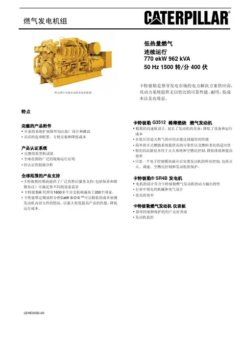
燃气发电机组低热量燃气连续运行770 ekW 962 kVA50 Hz 1500 转/分 400 伏卡特彼勒是领导发电市场的电力解决方案供应商,其动力系统提供无以伦比的可靠性能、耐用、低成本以及高效益。
所示图片可能未反映实际的机器完整的产品附件• 全套的系统扩展附件均由原厂设计和测试• 灵活的选项配置,方便安装和降低成本产品认证系统• 完整的原型机试验• 全球范围的广泛的现场运行证明• 经认证的扭振分析全球范围的产品支持• 卡特彼勒经销商提供了广泛的售后服务支持(包括保养和维修协议)可满足你不同的设备需求• 卡特彼勒® 代理有1600多个分支机构遍布于200个国家。
• 卡特彼勒定期油样分析Cat® S·O·S sm可以极低的成本侦测发动机内部元件的情况,以最大程度提高产品的性能、降低运行成本。
卡特彼勒 G3512 稀薄燃烧 燃气发动机• 精致的高速机设计,延长了发动机的寿命,降低了设备和运行成本• 在低压管道天然气的应用出能达到最佳的性能• 简单的开式燃烧系统提供高的可靠性以及燃料变化的适应性• 领先的高新技术用于点火系统和空燃比控制,降低排放和提高效率• 只需一个电子控制模块就可以实现发动机的所有控制,包括点火、调速、空燃比控制和发动机的保护。
卡特彼勒® SR4B 发电机• 电机的设计符合卡特彼勒燃气发动机的动力输出特性• 行业中领先的机械和电气设计• 更高的效率卡特彼勒燃气发动机仪表板• 简单控制和保护的用户友好界面• 发动机监控特点出厂标配件和选配件系统 标准 可选用的 进气 空气过滤器 空滤更换指示器(散供) 空气进气适配器控制面板 仪表板安装在发动机上冷却 缸套水冷却回路缸套水泵由发动机驱动,温控节温器联合式后冷却和润滑油冷却回路,一级为分道式后冷却器泵由发动机驱动,第二级温控节温器。
耐腐蚀型冷却器 原水冷却器选用热电联供时,可调节冷却温度 进/出水接口连接膨胀溢流水箱液位开关器排气 湿式排气管 弯头,柔性连接,法兰带灭火星的消声器 消声器连接法兰燃料 Deltec天然气混合器发动机后部输入连接燃料热值17.7-23.6MJ/Nm3 (450-600Btu/scf)燃气过滤器 燃气关断阀发电机 SR4B发电机,包括:永磁励磁,绕组模绕结构,H级的绝缘定子温度侦测RTD卡特彼勒CDVR自动电压调节数字模块无功和功率因数KVAR/PF控制防结露线圈空间加热器 整套断路器安装中压发电机轴承温度侦测RTD低压扩展箱母线引入箱发电机用空气过滤器 欧洲标准母线调速 速度控制器Woodward 2301A可满足标准排放 散供 Woodward 2301A2301A负荷分配控制执行器2301D 双增益控制8290负荷分配模块点火 卡特彼勒电子点火系统(E.I.S)爆震正时传感器润滑 曲轴箱呼吸器,顶部安装润滑油冷却器润滑油过滤器浅式油底壳 润滑油油位计 油底壳排放阀 排放泵预润滑泵润滑油安装 330mm结构钢底座 工业级 弹簧式减震块橡胶式减震块保护 24V直流燃气关断电磁阀(通电打开)爆震停机起动/充电 24V起动马达 蓄电池及其电缆和支架电池充电器 充电发电机超大容量电池缸套水加热器其他 卡特彼勒黄色油漆(除水箱和底座)保护曲轴减震器起重吊眼操作和维护手册,零件手册 曲轴箱防爆阀 发动机盘车组件 EEC D.O.I证书技术规格卡特彼勒SR4B发电机机架号 695 励磁 永励磁 节距 0.7333 级数 4 轴承数 1 引线数 6 绝缘 H级 IP等级 防滴漏保护IP22 安装对中 导向轴 超速能力 额定转速的125% 波形偏差(线到线,无负载) 小于3.0% 电压调节器 CDVR 电压调整范围 +/-5.0% 稳态电压调节率 +/-0.5%电压调节率(在3%速度变化内) +/-0.5% 电话影响系数(TIF) 小于50电压种类请咨询当地的卡特彼勒经销商 卡特彼勒燃气发动机仪表板 * 包括:润滑油压力冷却水温润滑油压差进气温度检修时间排气温度计和热电偶进气压力计量卡特彼勒燃气发动机G3512 LE SCAC 4冲程、 火花塞点火燃气发动机缸数 V12缸径mm(in) 170(6.7)冲程mm(in) 190(7.5)排量 L(in) 51.8(3158)压缩比 11:01吸气方式 涡轮增压后冷却回路冷却方式 缸套水,分道式后冷却和润滑油冷却器为一个回路燃料系统 低压执行器类型 Woodward2301A 资料和技术规格可能会有更改,不作另行通知,在本出版物中使用国际单位(SI)技术数据G3512 燃气发电机机组DM 0762排放标准(氮氧化合物NOx) 分道式后冷却 mg/Nm3Deg C50054机组性能 (1)发电机组额定功率@0.8pf(含水泵和不含风扇) 发电机组额定功率@0.8pf(含水泵和不含风扇) 发电机组额定功率@1.0pf(含水泵和不含风扇) 电能效率@1.0pf(ISO 3046/1)(2)机械功率(含水泵和不含风扇) ekW 连续运行kVA 连续运行ekW 连续运行%bkW77096277631.9803燃气消耗量(3)100%负荷(不含风扇) 75%负荷 (不含风扇) 50%负荷 (不含风扇) Nm3/hrNm3/hrNm3/hr391320232海拔高度能力(环境温度25℃时)海拔高度 M500 冷却系统环境温度缸套水出口温度(最高) Deg CDeg C25110排气系统燃烧用空气流量 排气管气体温度 排气流量 Nm3/minDeg CNm3/min50.149154.1机器散热缸套水冷却的散热中冷冷却回路+润滑油冷却回路的散热 废气散热(LHV 至25℃)废气散热(LHV 至120℃)从发动机发散到大气的热量从发电机发散到大气的热量 kWkWkWkWkWkW67024565953710334.6交流发电机 机架温升30%压降时的马达启动能力(4)Deg CskVA6951052521排放(5)氮氧化合物 NOx—含5%的氧(干燥的气体) 一氧化碳 CO—含5%的氧(干燥的气体)总碳氢含 THC—5%的氧(干燥的气体)非甲烷总烃NMHC—含5%的氧(干燥的气体) 废气含氧量(干燥的气体) mg/Nm3mg/Nm3mg/Nm3mg/Nm3%500187014062116.3工况定义与条件(1)连续运行—输出最大功率并且无运行时间的限制功率定义条件:输出功率基于天然气低热值(LHV)为22.4 MJ/Nm3, 和卡特彼勒甲烷数MN为130的稳态工况。

Internal combustion engine 内燃机Power unit 动力装置Spark ignition engine 火花塞点火式发动机Compression ignition engine 压燃式发动机Two-stroke/Four-stroke engine 二冲程/四冲程发动机Direct/Indirect injection engine 直喷式发动机/非直喷式发动机Reciprocating internal combustion engine 往复式内燃机Carburetor engine 化油器式发动机Rotary engine 转子发动机Supercharged engine 增压发动机Airoil-cooled engine 风冷油冷发动机Naturally aspirated engine 自然吸气发动机Liquefied petroleum gas engine 液化石油气发动机Diesel gas engine 柴油煤气发动机Multi-fuel engine 多燃料发动机Opposed-cylinder/Opposed-piston engine 对置气缸/对置活塞发动机Cross head engine 十字头型发动机In-line engine 直列式发动机Radial engine 星型发动机Stirling engine 斯特林发动机Front-engine 前置式发动机Rear-engine 后置式发动机Central engine 中置式发动机汽油机gasoline engine 汽油喷射式汽油机gasoline-injection engine 柴油机diesel engine 旋轮线转子发动机rotary trochoidal engine Leftright-hand engine 左右侧发动机Dual overhead camshaft engine 双顶置凸轮轴发动机DOHC valve in-head engine 顶置气门发动机side valve engine 侧置气门发动机multi-valve engine 多气门发动机horizontal engine 卧式发动机vertical engine 立式发动机oversquare/undersquare engine 短冲程/长冲程发动机engine performance 发动机性能twofour-stroke cycle 二四冲程循环diesel cycle 狄塞尔循环otto cycle 奥托循环mixed cycle 混合循环constant volumepressure cycle 等容等压循环woking cycle 工作循环ideal cycle 理想循环thermodynamic cycle 热力循环up down stroke 上下行程intake stroke 进气行程charging stroke 充气行程compression stroke 压缩行程expansion stroke 膨胀行程power stroke 作功行程exhaust stroke 排气行程top bottom dead center 上下止点BTDC before top dead center 上止点前ATDC after top dead center 上止点后Bore 缸径Cylinder clearance volume 气缸余隙容积Combustion chamber volume 燃烧室容积Displacement 排量Compression ratio 压缩比Critical compression ratio 临界压缩比Expansion ratio 膨胀比Surface to volume ratio 面容比Stroke-bore ratio 行程缸径比Compression pressure 压缩压力BMEP brake mean effective pressure 制动平均有效压力Air fuel ratio fuel air ratio 空燃比燃空比Fuel equivalence ratio 燃料当量比Power per litter cylinder 升功率单缸功率Gross power horse power 总功率马力Net power 净功率Fuel consumption 燃油消耗量Specific fuel consumption 比燃油消耗率Power curve 功率曲线Mechanical loss 机械损失Mechanical efficiency 机械效率Effective thermal efficiency 有效热效率Volumetric efficiency 充气系数Coefficient of excess air 过量空气系数Coefficient of torque adaptability 扭矩适应性系数Coefficient of intensification 强化系数Correction factor 校正系数Economic speed 经济转速Starting speed 启动转速Speed at maximum torque 最大扭矩转速Maximum no load governed speed 最高空转转速Speed governing 调速Working condition 工况Declared working condition 额定工况Variable working condition 变工况Steady working condition 稳定工况No-load 空载Full part load 全负荷部分负荷Major pitchminor diameter 外中、内径Radical clearance 径向间隙Loading startingacceleration performance 加载性能启动性能、加速性能Power emission performance 动力性能排放性能Part throttle characteristics 负荷特性Governorcontrol characteristics 调速特性Mapping characteristics 万有特性Steady state speed governing rate 稳态调速率Cylinder block head 缸体缸盖Cylinder head gasket 气缸盖垫片Cylinder liner sleeve 缸套Dry wet cylinder liner 干湿缸套Water jacket 气缸水套Cylinder wall 气缸壁Deformation 变形Cavitation 穴蚀Aging 老化Fatigue 疲劳Rough running 工作粗暴Knock 敲缸Cylinder score 拉缸Dynamometer 测功机Automobile Mechanics 汽车构造Engine Cylinder Block Crankcase 发动机气缸休曲轴箱Piston Connecting Rod 活塞连杆Crankshaft Flywheel 曲轴飞轮Valves and Valves Train 气门与气门传动组Engine Fuel System 发动机燃油系统Engine Lubricating System 发动机润滑系统Engine Cooling System 发动机冷却系统engine Ignition System 发动机点火系统engine Starting System 发动机起动系统Clutch 离合器Transmission 变速器Suspension System 悬挂系统Crank shaft 曲轴Oil pan 油底壳Piston pin ring 活塞销环Valve timing 配气相位VVTVariable Valve Timing 可变气门相位VVT-iVariable Valve Timing Intake 智能可变配气正时VVTLVariable Valve Timing and Lift 可变气门相位及升程VTECVariable Valve Timing and Lift Electronic Control System 可变气门相位及升程电子控制系统FSI Fuel Straight Injection 汽油机缸内直喷技术OBD On Board Diagnostics 车载故障诊断系统VCMVariable Cylinder Management 可变气缸管理即闭缸技术Muffler 消音器volume ratio of combustion cahmber燃烧室容积比surface-volume ratio of combustion chamber燃烧室口径比flywheel cover飞轮壳dome head piston圆顶活塞flat head piston平顶活塞crown head piston convex head piston 凸顶活塞concave head piston凹顶活塞piston skirt活塞裙部oil control ring 油环connecting rod small end连杆小头connecting rod big end连杆大头connecting rod bearing连杆轴承one-piece crankshaft整体式曲轴assembled crankshaft组合式曲轴crankshaft main journal 曲轴主轴颈crank pin曲柄销eccentric shaft偏心轴crankcase曲轴箱flywheel飞轮reciprocating inertia force1st order一级往复惯性力reciprocating inertia force 2nd order二级往复贯性力camshaft bearing journal凸轮轴轴颈camshaft bearing 凸轮轴轴承camshaft gear wheel 凸轮轴齿轮inlet cam进口凸轮exhaust cam排气凸轮timing gear正时齿轮swirl rate进气涡流intake turbulence进气紊流valve lift气门升程valve timing气门正时valve guide气门导管roller 滚柱rocker arm摇臂fuel delivery per cycle循环供油量rated fuel delivery 额定供油量fuel injection beginning喷油始点fuel injection end喷油终点fuel injection duration angle喷油持续角injection delay喷油延迟pilot injection 引燃喷射injection starting pressure启喷压力carburetor化油器governor 调速器air filter空气滤清器intake preheater进气预热装置intake manifold进气歧管indicated power指示功率indicated thermal efficiency指示热效率indicated specific energy consumption指示油耗率indicator diagram示功图mechanical supercharging机械增压supercharge ratio增压比boost pressure增压压力surge喘振standard atmospheric conditions标准大气状况atmospheric pressure 大气压力inlet air temperature进气温度performance test性能试验thermo-shock test热冲击试验cylinder fuel-cut test停缸试验turbo-charger matching test增压机匹配试验exhaust analysis test排气分析试验stability test稳定性试验verification test验证试验approval test鉴定试验reliability test可靠性试验durability test耐久性试验type approval test定型试验acceptance test验收试验field test现场试验delivery test出厂试验spot check test抽查试验re-check test复查试验bench test台架试验hydraulic dynamometer水力测功机eddy current dynamometer电涡流测功机electric dynamometer电力测功机fuel and vapor separator油气分离器catalyst催化剂converter转化器catalytic converter催化转化器oxidation catalyst氧化型催化剂reduction catalyst还原型催化剂three-way catalyst三元催化剂catalyst poisoning催化剂中毒lean rich mixture稀浓混合气temperature sensor温度传感器pressure sensor压力传感器position sensor位置传感器speed sensor转速传感器knock sensor爆震传感器nondispersive infrared不分光红外线分析法nondispersive ultraviolet不分光紫外线分析法flame ionization ditector氢火焰离子化检测器gas chromatograph气相色谱仪heated flame ionization detector加热式氢火焰离子化检测器opacimetersmokemeter烟度计off-road vehicle越野车sports car跑车racer racing car赛车interchangeability 互换性final assembly 总装dash board 仪表盘clean diesel 清洁柴油grade ability 爬坡能力moisture ejector 除湿器modular bus body 组合式客车车身test of steering wheel returnability 转向盘回正性试验steering wheel impulse input test 转向盘转角脉冲试验air deflector 空气导流板steering wheel step input or transient state yaw response test 转向盘转角阶跃输入试验limiting lateral acceleration test 极限侧向加速度试验automobile ride random input running test 汽车平顺性随机输入行驶试验automobile ride single pulse input running test 汽车平顺性单脉冲输入行驶试验measurement of natural frequency and damping ratio of suspension 汽车悬挂系统固有频率与阻尼比的测定试验test of effect of sudden power change 功率突然变化影响试验test of control at breakway 收油门后控制试验test of crosswind stability 横向稳定性试验kick-back test 反冲试验test of burst response of tyre 轮胎爆破响应时间试验obstacle avoidance test 绕过障碍物试验lane change test 移线试验test of J turn J型转弯试验frequency response test 频率响应时间试验transient response test 瞬态响应时间试验step response test 阶路响应时间试验pulse response test 脉冲响应试验static steering effort test 静态操舵力试验jack-up test of suspension 悬架举升试验test of overturning immunity 耐翻倾试验rim slip test 转毂错动试验wind tunnel test 风洞试验test of breaking stability 制动稳定性试验minimum turning diameter test 最小转弯直径试验steering effort test 操舵力试验汽车automobile 拖拉机tractor 铁路机车locomotive 有轨电车tram 无轨电车trolley 军用车辆military vehicle 蒸汽机steam engine 煤气机gas engine 汽油机gasoline engine 国民经济national economy 国内生产总值GDP Gross Domestic Production 全拆散CKD Completely Knock Down 半拆散SKDSemi-Knock Down 改革开放reform and opening 技术引进technical import 国产化localization 支柱产业pillar estate 轿车car 客车bus coach 货车truck lorry 公路用车road vehicle 非公路用车off-road vehicle 发动机engine 机体engine body 曲柄连杆机构crank-connecting rod mechanism 配气机构valve timing mechanism 供给系fuel supply system 冷却系cooling system 润滑系lubricating system 点火系ignition system 起动系starting system 底盘chassis 传动系power train 离合器clutch 变速器gear box 传动轴propeller shaft 驱动桥drive axle 行驶系runninggear 车架frame 悬架suspension 前轴front axle 桥壳axle housing 车轮wheel转向系steering system 转向盘steering wheel 转向器steering gear 转向传动装置steering linkage 助力装置power assisting device 制动系braking system 控制装置control device 供能装置power supply device 传动装置transfer device 制动器brake 车身body 车前板制件front end panels 车身壳体body shell 车门door 车窗window 附属装置auxiliary device 货箱carrying platform 发动机前置后轮驱动FR front engine rear drive 发动机前置前轮驱动FF front engine front drive 发动机后置后轮驱动RR rear engine rear drive 发动机中置后轮驱动MR midship engine rear drive 全轮驱动nWD all wheel drive 驱动力tractive force 阻力resistance 滚动阻力rolling resistance 空气阻力air resistance drag 上坡阻力gradient resistance 附着作用adhesion 附着力adhesive force 附着系数coefficient of adhesion 第一章发动机工作原理二冲程发动机two stroke engine 四冲程发动机four stroke engine 水冷发动机water cooled engine 风冷发动机air cooled engine 上止点UDP upper dead point 下止点LDP lower dead point 活塞行程stroke 汽缸直径bore 工作容积working volume 排量swept volume displacement 进气行程intake stroke 压缩行程compression stroke 压缩比compression ratio 做功行程working stroke 爆燃敲缸detonation knock 排气行程exhaust stroke 示功图indicating diagram 汽缸体cylinder block 汽缸盖cylinder head 油底壳oil sump 活塞piston 连杆connecting rod 曲轴crankshaft 飞轮flywheel 进气门intake valve 排气门exhaust valve 挺柱tappet 推杆push rod 摇臂rocker 凸轮轴camshaft 正时齿轮timing gear 燃油箱fuel tank 燃油泵fuel pump 汽油滤清器gasoline filter 化油器carburetor 空气滤清器air cleaner 进气管intake manifold 排气管exhaust manifold 火花塞spark plug 点火线圈ignition coil 断电器breaker 蓄电池storage battery 发电机generator 水泵water pump 散热器radiator 风扇fan 放水阀drain valve 水套water jacket 分水管distributive pipe 机油泵oil pump 集滤器suction filter 限压阀relief valve 润滑油道oil passage 机油滤清器oil filter 机油冷却器oil cooler 起动机starting motor 有效功率effective power 有效转矩effective torque 燃油消耗率specific fuel consumption 发动机转速特性engine speed characteristic 节气门开度throttle percentage 部分特性partial characteristic 外特性outer characteristic 第二章曲柄连杆机构汽缸套cylinder sleeve cylinder liner 发动机支承engine mounting 活塞顶piston top 活塞头部piston head 活塞裙piston skirt 开槽slot 活塞环piston ring气环compression ring 油环oil ring 环槽groove 活塞销piston pin 主轴承main bearing 主轴承盖main bearing cap 主轴瓦main shell 连杆轴承big end bearing 连杆盖big end cap 起动爪cranking claw 带轮pulley 平衡重counter weight 发火顺序firing order 扭振减振器torsional vibration damper 第三章配气机构顶置气门OHV Over Head Valve 顶置凸轮轴OHC Over Head Camshaft 单顶置凸轮轴SOHC Single Over Head Camshaft 双顶置凸轮轴DOHC Dual Over Head Camshaft 多气门发动机multi-valve engine 气门间隙valve clearance 配气相位timing phase 气门杆valve stem 气门座valve seat 气门导管valve guide 气门弹簧valve spring 第四章汽油机供给系可燃混合气combustion mixture 消声器silencer muffler 汽油gasoline petrol 分馏distil 蒸发性evaporating property 热值heat value 抗爆性anti-knock property 辛烷值RON Research Octane Number 过量空气系数coefficient of excessive air 理论混合气theoretical mixture 稀混合气thin mixture 浓混合气thick mixture 主供油系统main supply system 怠速系统idle system 加浓系统thickening system 加速系统accelerating system 浮子float 浮子室float chamber 针阀needle valve 量孔metering jet 阻风门choke 滤芯filter cartridge 沉淀杯sediment cup 泵膜pump diaphragm 油浴式oil bath type 石棉垫aestos pad 预热pre-heating 汽油直接喷射gasoline direct injection 电控electronic control 多点喷射muti-point injection 单点喷射single point injection 电路控制circuit control 分电器信号distributor signal 空气流量信号airflow signal 冷却水温信号water temperature signal 第五章柴油机供给系输油泵transfer pump 喷油泵fuel injection pump 高压油管high pressure fuel pipe 发火性ignition property 黏度viscosity 凝点condensing point 备燃期pri-combustion period 速燃期rapid combustion period 缓燃期slow combustion period 燃烧室combustion chamber 统一燃烧室united chamber 球形燃烧室ball shape chamber 涡流室turbulence chamber 预燃室pri-combustion chamber 喷油器injector 精密偶件precise couple 柱塞plunger 出油阀delivery valve 调速器governor 两速调速器two speed governor 全速调速器full speed governor 定速调速器fixed speed governor 综合调速器combined governor 气动调速器pneumatic governor 机械离心式调速器mechanical centrifugal governor 复合式调速器complex governor 喷油提前角调节装置advancer 飞块flyweight 联轴节coupling 粗滤清器primary filter 细滤清器secondary filter 涡轮增压器turbocharger 中间冷却器intermediate cooler 第七章冷却系节温器thermostat 防冻液anti-freezing liquid 补偿水桶compensation reservoir V-带V belt 百叶窗shutter 大循环big circulation 小循环small circulation 散热翅片fins 第八章润滑系润滑剂lubricant 压力润滑pressure lubrication 飞溅润滑splash lubrication 润滑脂grease 机油压力传感器oil pressure sensor 油封oil seal 旁通阀bypass valve 机油散热器oil cooler 机油尺dip stick 加机油口oil filler 曲轴箱通风crankcase ventilation 第九章点火系一次绕组primary winding 二次绕组secondary winding 热敏电阻heat sensitive resistance 点火提前ignition advance 分电器distributor 活动触点moving contact 固定触点fixed contact 分火头distributor rotor arm 电容器condenser 点火提前装置ignition advancer 离心式点火提前装置centrifugal ignition advancer 真空式点火提前装置vacuum ignition advancer 辛烷值校正器octane number rectifier 中心电极central electrode 侧电极side electrode 瓷绝缘体ceramic insulator 跳火间隙spark gap 半导体点火系semi-conductor ignition system 晶体管transistor 二极管diode 三极管triode 无触点点火系non-contact ignition system 霍尔效应Hall effect 正极板anode 负极板cathode 隔板separator 电解液electrolyte 蓄电池格battery cell 接线柱terminal 电缆cable 硅整流交流发电机silicon rectified A.C.。

1SeriesWhat is a Programmable Room Thermostat?A programmable room thermostat is both a programmer and a room thermostat.A programmer allows you to set “On” and “Off” periods to suit your own lifestyle.A room thermostat works by sensing the air temperature, switching on the heating when the air temperature falls below the thermostat setting, and switching it off once this set temperature has been reached.So a programmable room thermostat lets you choose what times you want the heating to be on, and what temperature it should reach while it is on. It will allow you to select different temperatures in your home at different times of the day (and days of the week) to meet your particular needs and preferences.Setting a programmable room thermostat to a higher temperature will not make the room heat up any faster. How quickly the room heats up depends on the design and size of the heating system.Similarly reducing the temperature setting does not affect how quickly the room cools down. Setting a programmable room thermostat to a lower temperature will result in the room being controlled at a lower temperature, and saves energy.Installation ProcedureThe neoStat V2 is designed to be flush mounted and requires a back box of 35mm (minimum depth) to be sunk into the wall prior to installation.Step 1 Using a small screwdriver, slightly loosen the screw from the bottom face of the thermostat. Then carefully separate the front half from the back plate.Step 2 Place the thermostat front somewhere safe. Terminate the thermostat as shown in the diagrams on pages 28-31 of this booklet. Note: For time clock wiring connections, terminate as shown on page 38.Step 3 Screw the thermostat back plate securely into the back box.Step 4 Clip the front of the thermostat onto the back plate, securing it in place with the retaining screw.Do Mount the thermostat at eye level.Read the instructions fully so you get the best from our product.Don’t Do not install near to a direct heat source as this will affect functionality. Do not push hard on the LCD screen as this may cause irreparable damage.12 34This neoStat V2 can either be used as a thermostat or a time clock. Thermostat mode is the default setting.To change between thermostat or time clock modes, follow these steps.• ..........................................................................• Press and hold the Tick button for 3 seconds ...............................................................• SETUP will be highlighted, now press and hold the tick key for 10 seconds .....• Use the Left / Right keys to scroll between modes .....................................................Mode 1 = ThermostatMode 2 = Time Clock• Press the Tick key to confirm selection ............................................................................The neoStat V2 will revert to the main display screen for the selected mode.For time clock mode instructions, first pair the time clock with the neoHub as explained on page 8, then turn to page 33.Mode Select, press and hold Tick ........... ETUP will be highlighted, now press the tick key once .....................................................What is a Mesh NetworkApproach SensorNeoStats work using a mesh network, meaning neoStats have the ability to send & receive signals via other thermostats on the network. This signal is relayed from one thermostat to another until it reaches its destination. This communication method extends the communication range whilst offering increased network stability when compared with standard RF thermostats.The Mesh symbol is shown when the device is communicating with the neoHub, if theThe neoStat V2 uses proximity to detect when you are about to use the touch keys. As you approach the neoStat V2, the touch keys and backlight will light up.This can be useful if you need to adjust the set temp or timer in a dark room.• Press the Tick key once again to pair the neoStat to the neoHub .................• The MESH symbol appears flashing on the display.• When the neoStat V2 successfully connects to the neoHub the MESH symbol will be permanently displayed.• Press ADD ANOTHER for addtional zones or press FINISH to complete setup.Please note, you only have to pair the hub to your account once.To pair any additional neoStats, select ZONES, edit, then ADD ZONE.Mode 1 - ThermostatThe neoStat V2 can be configured for different sensor options such as built in air sensor, floor sensor or both. The display will clearly indicate which sensor is being usedby showing either “Room Temp” or “Floor Temp” before the actual temperature value.When the neoStat V2 is set to use both the air & the floor sensor, the room temperature will be displayed by default.To view the current floor temperature, press and hold the Left and Right arrow keys for 5 seconds, the floor temperature will then be displayed ....................Temperature DisplayRoom Temperature Floor Temperaturese the down arrow to scroll to .................................................................................. ress Tick to turn the display on .......................................................................................TimeComfort Levels ExplainedThe neoStat V2 offers three program mode options; Weekday/Weekend programming, 7 Day programming and 24 Hour programming. There is also the option to use the thermostat as a Non-Programmable thermostat.When thermostats are connected to the mesh network, the program mode forthe system is configured by using the neoApp.The thermostat is supplied with comfort levels already programmed, but these can be changed easily. The default times and temperature settings are;07:00 - 21°C (Wake) 09:00 - 16°C (Leave) 16:00 - 21°C (Return) 22:00 - 16°C (Sleep)If you only want to use 2 levels, you should program the unused levels to --:--For Weekday/Weekend programming, the four comfort levels are the same for Mon-Fri, but can be different for Sat-Sun. For 7 Day programming each day of the week can have four different comfort levels. In 24 Hour mode all days are programmed with the same comfort levels.• To program the comfort levels, use the Left / Right keys to scroll to EDIT .............• Press Tick to confirm selection ......................................................................................................• Use the Left / Right keys to select day / period of week (the selection will flash).• Press Tick to confirm selection ......................................................................................................• WAKE will now flash and the current time and temperature setting will be shown.• Press Tick to alter WAKE settings ...................................................................................................Temperature ControlThe Up / Down keys allow you to adjust the set temperature ..................................When you press either key, you will see the word SET and the desired temperature value. Use the Up / Down keys to adjust the SET value .....................Press Tick to confirm settings and return to the main display ...........................................Note: This new temperature is maintained only until the next programmed comfort level.At this time, the thermostat will revert back to the programmed levels.Set IconSet TemperatureTo cancel a temperature Hold, with hold selected on the main menu, press the tick key and then press tick again while Cancel is highlighted.Hold Time RemainingHold Left IndicatorUse the Left / Right keys to scroll to HOLD.................................................................The time will countdown the set duration and then revert to the normal program.Locking the neoStat V2The neoStat V2 has a keypad lock facility. To activate the lock follow these steps.•Use the ‘Left/Right’ keys to scroll to ‘HOLD’ & press for 10 seconds ........ The display will show 0000. At this point enter a four digit pin number.•Use the Up / Down keys to enter the first two digits ........................................• Press to confirm .................................................................................................................• Use the Up / Down keys to enter the second two digits .................................• Press to confirm .................................................................................................................The display will return to the main screen and display the keypad lock indicator ......Note: The keypad lock indicator is only displayed when the lock is active.To unlock the neoStat V2 press Tick once. The display will show 00:00 and you will need to enter the four digit pin number you set previously.• Use the Up / Down and keys to enter the first two digits ........................... • Use the Up / Down and keys to enter the second two digits ...................The display will unlock and return to the main screen.Unlocking the neoStat V2Use the Left / Right keys to scroll to the Power Icon ..................................................To cancel the frost protect mode, navigate to the Power button again and press Tick.Frost ProtectionMode EnabledPower On/OffThe heating is indicated ON when the flame icon is displayed.When the flame icon is absent, there is no requirement for heating to achieve the set temperature but the neoStat remains active.To turn the neoStat V2 off completely, scroll to the Power Icon and holdthe Tick key for approximately 3 seconds until the display goes blank ....................The display and heating output will be turned OFF.To turn the thermostat back ON, press the Tick key once ..............................................................Thermostat completely OFF Thermostat powered ONOptional Settings ExplainedTHE FOLLOWING SETTINGS ARE OPTIONAL AND IN MOST CASES NEED NOT BE ADJUSTED.Feature 01 – Pairing To neoHub: This function is used to connect the thermostat to the neoHub.Feature 02 - Switching Differential: This function allows you to increase the switching differential of the thermostat. The default is 1°C which means that with a set temperature of 20°C, the thermostat will switch the heating on at 19°C and off at 20°C. With a 2°C differential, the heating will switch on at 18°C and off at 20°C.Feature 03 - Frost Protect Temperature: This is the temperature maintained when the thermostat is in Frost Mode. The range is 07 - 17°C. The default is 12°C and is suitable for most applications.Feature 04 – Output Delay: To prevent rapid switching, an output delay can be entered. This can be set from 00 - 15 minutes. The default is 00 which means there is no delay. Feature 05 – Temperature Up/Down Limit: This function allows you to limit the use of the up and down temperature arrow keys. This limit is also applicable when the thermostat is locked and so allows you to give others limited control over the heating system.Feature 06 – Sensor Selection: On this neoStat, you can select which sensor should be used. You can select between air temperature only, floor temperature, or both. When you enable both sensors, the floor sensor is used as a floor limiting sensor and is designed to prevent the floor from overheating...............................................................• Use the Up / Down keys to scroll through features ..................................................• Use the Left / Right keys to adjust the setting within each feature ....................• Press Tick to confirm and exit setup menu ..................................................................Setting ValueFeature NumberRe-calibrating the ThermostatIf you need to re-calibrate the thermostat, follow these steps.•• Press and hold Tick to turn the display OFF ..........................................................• Press and hold the Tick and Down keys together for 10 seconds .................• The current temperature will appear on the display.•Use the Up / Down keys to configure the new temperature value .............••............................................................•Press the Tick key once to turn the thermostat ON ............................................Error CodesE0 = The internal sensor has developed a fault.E1 = The remote FLOOR probe has not been connected. T he remote FLOOR probe has not been wired correctly.The remote FLOOR probe is faulty.E2 = The remote AIR probe has not been connected. The remote AIR probe has not been wired correctly. The remote AIR probe is faulty.When terminated for thermostat operation the screen will display an error code if a fault is detected.Wiring Diagram - neoStat to Boiler VoltfreeLIVE230V SUPPLY INThis product must only be installed by a qualified electricianand comply with local installation regulations.Wiring DiagramneoStat to UH8 and Optional Remote Probe Connections(Optional)This product must only be installed by a qualified electrician and comply with local installation regulations......................................................................• Press and hold Tick to turn the display OFF ............................................................• SETUP will be highlighted ..............................................................................................• Press and hold the Tick key for 10 seconds ..................................................................• Press the Tick key to confirm selection .....................................................................6 SeriesSetting the Switching TimesTo program the switching times, follow these steps.• U se the Left / Right keys to scroll to EDIT and press Tick .................................• U se the Left / Right keys to select day/period of the week .............................• P ress Tick to confirm selection ................................................................................... 1 will now flash and the current ON time will be displayed. The OFF time can be viewed by pressing the Down key .................................• S elect a switching time and press the Tick key ....................................................• U se the Up / Down keys to select the ON time HOURS and press Tick .......• U se the Up / Down keys to select the ON time MINUTES ................................• P ress Tick to confirm selection ..................................................................................• U se the Up / Down keys to select the OFF time HOURS and press Tick .....• U se the Up / Down keys to select the OFF time MINUTES ..............................• P ress Tick to confirm selection ..................................................................................• P ress the Right arrow key ............................................................................................ 2 will now flash and the current ON time will be displayed.•R epeat the steps above to set all periods. For any unused periods enter -- : -•When complete, use the Left / Right keys to scroll to DONE and pressTick to confirm all changes ........................................................................................Optional Settings - Feature Table 02FEATUREProgram Mode DESCRIPTION 01 = Weekday/Weekend Programming (Default)02 = 7 Day Programming03 = 24 Hour ModeSETTING Optional Features ExplainedFeature 01 – Pairing To neoHub: This function is used to connect the time clock to the neoHub.Feature 02 - Weekday/Weekend (5/2), 7 Day Programming or 24 Hour Mode: The time clock offers three programming methods;Weekday/ Weekend (5/2) - Allows you to program 4 on/off switching times for the weekdays and 4 on/off switching times for the weekend.7 Day Program Mode - Each day has 4 on/off switching times that can be programmed independently.24 Hour Mode - All days are programmed with the same on/off switching times.Notes......................................................................................................................................................................... ......................................................................................................................................................................... ......................................................................................................................................................................... ......................................................................................................................................................................... ......................................................................................................................................................................... ......................................................................................................................................................................... ......................................................................................................................................................................... ......................................................................................................................................................................... ......................................................................................................................................................................... ......................................................................................................................................................................... ......................................................................................................................................................................... ......................................................................................................................................................................... .................................................................................................................................................................................................................................................................................................................................................. ......................................................................................................................................................................... ......................................................................................................................................................................... ......................................................................................................................................................................... ......................................................................................................................................................................... ......................................................................................................................................................................... ......................................................................................................................................................................... ......................................................................................................................................................................... ......................................................................................................................................................................... ......................................................................................................................................................................... ......................................................................................................................................................................... ......................................................................................................................................................................... .........................................................................................................................................................................PDF FAQTwitter: @heatmiseruk Facebook: /thermostats。
v12digitalengine说明书
摘要:
1.V12DigitalEngine 简介
2.V12DigitalEngine 的功能
3.V12DigitalEngine 的使用方法
4.V12DigitalEngine 的优点和局限性
5.总结
正文:
V12DigitalEngine 是一款强大的数字引擎,适用于各种数字处理任务。
它具有强大的数据处理能力,可以轻松地执行大规模数据分析和计算。
V12DigitalEngine 的功能包括数据分析、数据挖掘、机器学习、人工智能等。
它可以处理各种类型的数据,包括结构化数据、非结构化数据、时空数据等。
此外,V12DigitalEngine 还具有可视化分析功能,可以直观地呈现数据分析结果。
使用V12DigitalEngine 非常简单。
用户只需要将数据输入到引擎中,然后选择需要的功能,就可以开始分析和计算了。
对于机器学习和人工智能任务,用户还可以通过V12DigitalEngine 的API 接口调用各种机器学习和深度学习算法。
V12DigitalEngine 的优点在于其强大的数据处理能力和高效的分析效率。
它可以大大提高数据分析和决策的效率,帮助用户更好地理解和利用数据。
然而,V12DigitalEngine 也存在一些局限性,例如它需要大量的计算资
源和存储空间,对于小规模的数据处理任务可能会显得过于庞大和复杂。
总的来说,V12DigitalEngine 是一款功能强大的数字引擎,适用于各种数字处理任务。
它的使用简单,效率高,可以帮助用户更好地理解和利用数据。
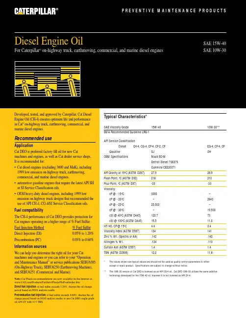
Typical Characteristics*SAE Viscosity Grade15W-4010W-30**EMA Recommended Guideline LRG-1API Service ClassificationDiesel CH-4, CG-4, CF-4, CF-2, CFCG-4, CF-4, CF Gasoline SJ SHOEM SpecificationsMack EO-M Detroit Diesel 7SE270Cummins CES20071API Gravity at 16ºC (ASTM D287)27.9 28.9Flash Point, ºC (ASTM D92)218 210Pour Point, ºC (ASTM D97)-33-33Viscosity:cP @ - 15ºC 3000 –cP @ - 20ºC –2840 cP @ - 25ºC 25,000–cP @ - 30ºC–19,500cSt @ 40ºC (ASTM D445)120.773cSt @ 100ºC (ASTM D445)15.511.0HT/HS, CP @ 15ºC 4.4 3.4Viscosity Index (ASTM D567)134141Zinc % Wt. (Spectro or AA).142.142Nitrogen % Wt. .124.113Sulfate Ash (ASTM D567) 1.4 1.4TBN (ASTM D2896)12.211.8* The values shown are typical values and should not be used as quality control parameters to either accept or reject product. Specifications are subject to change without notice.**The 10W-30 version of Cat DEO is licensed as an API CG-4 oil. Cat DEO 10W-30 utilizes the same additive technology developed for the 15W-40 oil, however it is not licensed as API CH-4.Title Title P R E V E N T I V E M A I N T E N A N C E P R O D U C T SSAE 15W-40SAE 10W-30Developed, tested, and approved by Caterpillar, Cat Diesel Engine Oil (CH-4) ensures optimum life and performance in Cat ®on-highway truck, earthmoving, commercial, and marine diesel engines.Recommended useApplicationCat DEO is preferred factory fill oil for new Catmachines and engines, as well as Cat dealer service shops. It is recommended for:• Cat diesel engines (excluding 3600 and MaK), including 1999 low emission on-highway truck, earthmoving,commercial, and marine diesel engines.• automotive gasoline engines that require the latest API SH or SJ Service Classification oils.• OEM heavy-duty diesel engines, including 1999 low emission on-highway truck designs that recommended the use of API CH-4, CG-4/SJ Service Classification oils.Fuel compatibilityThe CH-4 performance of Cat DEO provides protection for Cat engines operating on a higher range of % Fuel Sulfur:Fuel Injection Method % Fuel Sulfur Direct Injection (DI)0.05% to 1.20%Precombustion (PC)0.05% to 0.60%Information sourcesWe can help you determine the right oil for your Cat machines and engines or you can refer to your “Operation and Maintenance Manual” or service publications SEBU6385(On-Highway Truck), SEBU6250 (Earthmoving Machine),and SEBU6251 (Commercial and Marine).Note:Cat Fluids recommendations are now available on the Internet at: /Products/PartServ/Fluids/FluProd/index.htmDirect fuel injection –if fuel sulfur exceeds 1.20%, shorten the oil change period based on S •O •S analysis results.Precombustion fuel injection –if fuel sulfur exceeds 0.60%, shorten the oil change period based on S •O •S analysis results or use Cat DEO single-grade oil API CF with 13.5 TBN.Diesel Engine Oil For Caterpillar ®on-highway truck, earthmoving, commercial, and marine diesel enginesDiesel Engine Oil••••••••19302000908070605040P E R F O R M A N C E L E V E LYEARCAT Engines and CAT Oil Performance HistorySince its introduction in the late 80’s, the Cat DEO formulation has changed many times to keep pace with new engine technology. You can be assured when you buy Cat DEO that the current formulation exceeds the latest engine oil requirements for Cat Engines.* Engine oil licensed as API CH-4, is automatically approved as API CG-4 and CF-4.Diesel Engine Oil© 2000 Caterpillar。
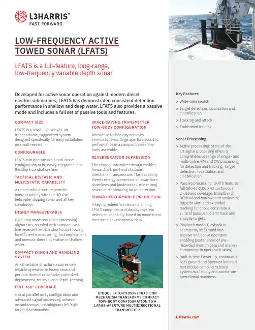
LOW-FREQUENCY ACTIVE TOWED SONAR (LFATS)LFATS is a full-feature, long-range,low-frequency variable depth sonarDeveloped for active sonar operation against modern dieselelectric submarines, LFATS has demonstrated consistent detection performance in shallow and deep water. LFATS also provides a passive mode and includes a full set of passive tools and features.COMPACT SIZELFATS is a small, lightweight, air-transportable, ruggedized system designed specifically for easy installation on small vessels. CONFIGURABLELFATS can operate in a stand-alone configuration or be easily integrated into the ship’s combat system.TACTICAL BISTATIC AND MULTISTATIC CAPABILITYA robust infrastructure permits interoperability with the HELRAS helicopter dipping sonar and all key sonobuoys.HIGHLY MANEUVERABLEOwn-ship noise reduction processing algorithms, coupled with compact twin line receivers, enable short-scope towing for efficient maneuvering, fast deployment and unencumbered operation in shallow water.COMPACT WINCH AND HANDLING SYSTEMAn ultrastable structure assures safe, reliable operation in heavy seas and permits manual or console-controlled deployment, retrieval and depth-keeping. FULL 360° COVERAGEA dual parallel array configuration and advanced signal processing achieve instantaneous, unambiguous left/right target discrimination.SPACE-SAVING TRANSMITTERTOW-BODY CONFIGURATIONInnovative technology achievesomnidirectional, large aperture acousticperformance in a compact, sleek tow-body assembly.REVERBERATION SUPRESSIONThe unique transmitter design enablesforward, aft, port and starboarddirectional transmission. This capabilitydiverts energy concentration away fromshorelines and landmasses, minimizingreverb and optimizing target detection.SONAR PERFORMANCE PREDICTIONA key ingredient to mission planning,LFATS computes and displays systemdetection capability based on modeled ormeasured environmental data.Key Features>Wide-area search>Target detection, localization andclassification>T racking and attack>Embedded trainingSonar Processing>Active processing: State-of-the-art signal processing offers acomprehensive range of single- andmulti-pulse, FM and CW processingfor detection and tracking. Targetdetection, localization andclassification>P assive processing: LFATS featuresfull 100-to-2,000 Hz continuouswideband coverage. Broadband,DEMON and narrowband analyzers,torpedo alert and extendedtracking functions constitute asuite of passive tools to track andanalyze targets.>Playback mode: Playback isseamlessly integrated intopassive and active operation,enabling postanalysis of pre-recorded mission data and is a keycomponent to operator training.>Built-in test: Power-up, continuousbackground and operator-initiatedtest modes combine to boostsystem availability and accelerateoperational readiness.UNIQUE EXTENSION/RETRACTIONMECHANISM TRANSFORMS COMPACTTOW-BODY CONFIGURATION TO ALARGE-APERTURE MULTIDIRECTIONALTRANSMITTERDISPLAYS AND OPERATOR INTERFACES>State-of-the-art workstation-based operator machineinterface: Trackball, point-and-click control, pull-down menu function and parameter selection allows easy access to key information. >Displays: A strategic balance of multifunction displays,built on a modern OpenGL framework, offer flexible search, classification and geographic formats. Ground-stabilized, high-resolution color monitors capture details in the real-time processed sonar data. > B uilt-in operator aids: To simplify operation, LFATS provides recommended mode/parameter settings, automated range-of-day estimation and data history recall. >COTS hardware: LFATS incorporates a modular, expandable open architecture to accommodate future technology.L3Harrissellsht_LFATS© 2022 L3Harris Technologies, Inc. | 09/2022NON-EXPORT CONTROLLED - These item(s)/data have been reviewed in accordance with the InternationalTraffic in Arms Regulations (ITAR), 22 CFR part 120.33, and the Export Administration Regulations (EAR), 15 CFR 734(3)(b)(3), and may be released without export restrictions.L3Harris Technologies is an agile global aerospace and defense technology innovator, delivering end-to-endsolutions that meet customers’ mission-critical needs. The company provides advanced defense and commercial technologies across air, land, sea, space and cyber domains.t 818 367 0111 | f 818 364 2491 *******************WINCH AND HANDLINGSYSTEMSHIP ELECTRONICSTOWED SUBSYSTEMSONAR OPERATORCONSOLETRANSMIT POWERAMPLIFIER 1025 W. NASA Boulevard Melbourne, FL 32919SPECIFICATIONSOperating Modes Active, passive, test, playback, multi-staticSource Level 219 dB Omnidirectional, 222 dB Sector Steered Projector Elements 16 in 4 stavesTransmission Omnidirectional or by sector Operating Depth 15-to-300 m Survival Speed 30 knotsSize Winch & Handling Subsystem:180 in. x 138 in. x 84 in.(4.5 m x 3.5 m x 2.2 m)Sonar Operator Console:60 in. x 26 in. x 68 in.(1.52 m x 0.66 m x 1.73 m)Transmit Power Amplifier:42 in. x 28 in. x 68 in.(1.07 m x 0.71 m x 1.73 m)Weight Winch & Handling: 3,954 kg (8,717 lb.)Towed Subsystem: 678 kg (1,495 lb.)Ship Electronics: 928 kg (2,045 lb.)Platforms Frigates, corvettes, small patrol boats Receive ArrayConfiguration: Twin-lineNumber of channels: 48 per lineLength: 26.5 m (86.9 ft.)Array directivity: >18 dB @ 1,380 HzLFATS PROCESSINGActiveActive Band 1,200-to-1,00 HzProcessing CW, FM, wavetrain, multi-pulse matched filtering Pulse Lengths Range-dependent, .039 to 10 sec. max.FM Bandwidth 50, 100 and 300 HzTracking 20 auto and operator-initiated Displays PPI, bearing range, Doppler range, FM A-scan, geographic overlayRange Scale5, 10, 20, 40, and 80 kyd PassivePassive Band Continuous 100-to-2,000 HzProcessing Broadband, narrowband, ALI, DEMON and tracking Displays BTR, BFI, NALI, DEMON and LOFAR Tracking 20 auto and operator-initiatedCommonOwn-ship noise reduction, doppler nullification, directional audio。
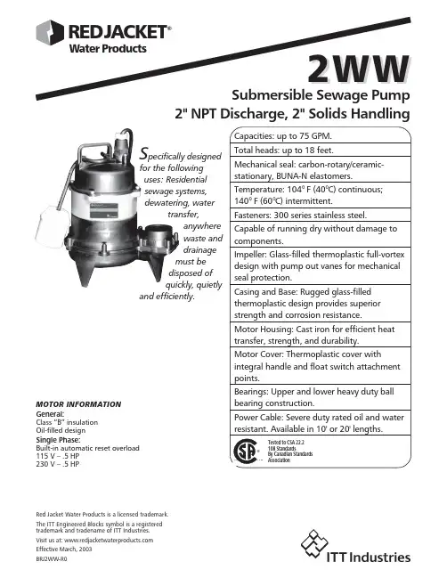
Red Jacket Water Products is a licensed trademark. The ITT Engineered Blocks symbol is a registered 2" NPT Discharge, 2" Solids HandlingS pecifically designedfor the followinguses: Residentialsewage systems,dewatering, watertransfer,anywherewaste anddrainagemust bedisposed ofquickly, quietlyand efficiently. General:Class “B” insulationOil-filled designSingle Phase:Built-in automatic reset overload115 V – .5 HP230 V – .5 HPMOTOR INFORMATIONTotal Head (ft. of water)Gallons Per Minute106312491431161418Single phase: 1⁄2 HP, 115 V or 230 V, 60 Hz, 1550 RPM,built in overload with automatic reset.Power cord: 10 foot standard length, 16/3 SJTW with molded NEMA three prong grounding plug. Optional 20foot length.Fully submerged in high grade turbine oil for lubrication and efficient heat transfer.Available for automatic and manual operation.Automatic models include Mechanical Float Switch assembled and preset at the factory.MOTOR FEATURESPERFORMANCE RATINGSPERFORMANCE CURVE2" NPT Discharge, 2" Solids HandlingT O T A L D Y N A M I C H E A DCAPACITYFEET2468101214163METERSRed Jacket Water Products is a licensed trademark.The ITT Engineered Blocks symbol is a registered Min.Float SwitchCord Discharge Min.Min.Min.Max.Shipping Order No.HP Volts Amps Circuit PhStyle Length Connection On Off Basin Solids Weight Breaker Level Level DiameterSizelbs/kg 2WW0511Plug / No Switch 10'Manual Manual 22 / 102WW0511A 1151320Piggyback / Wide-Angle10'15"9"23 / 10.42WW0511F .51Plug / No Switch 20'2"Manual Manual 18"2"22 / 102WW0511AF Piggyback / Wide-Angle20'15"9"23 / 10.42WW05122306.510Plug / No Switch 10'Manual Manual 22 / 102WW0512FPlug / No Switch20'ManualManual22 / 10MODEL INFORMATIONCOMPONENTS2" NPT Discharge, 2" Solids Handling106593128467Item No.Description1Impeller2Rugged thermoplastic base 3Rugged thermoplastic pump casing 4Mechanical seal 5Ball bearings 6O-rings 7Power cord 8Oil filled motor9Cast iron motor housing/stator assembly 10Thermoplastic motor cover(All dimensions are in inches. Do not use for construction purposes.)DIMENSIONS2" NPT Discharge, 2" Solids Handling。
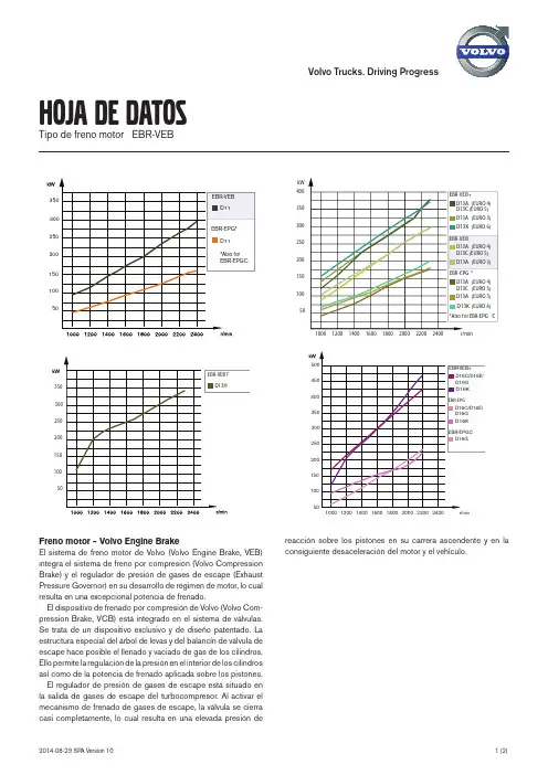
Volvo Trucks. Driving Progress50100150200250300350400kWHoja de datosTipo de freno motor EBR-VEBFreno motor – Volvo Engine BrakeEl sistema de freno motor de Volvo (Volvo Engine Brake, VEB)integra el sistema de freno por compresión (Volvo CompressionBrake) y el regulador de presión de gases de escape (ExhaustPressure Governor) en su desarrollo de régimen de motor, lo cualresulta en una excepcional potencia de frenado.El dispositivo de frenado por compresión de Volvo (Volvo Com-pression Brake, VCB) está integrado en el sistema de válvulas.Se trata de un dispositivo exclusivo y de diseño patentado. Laestructura especial del árbol de levas y del balancín de válvula deescape hace posible el llenado y vaciado de gas de los cilindros.Ello pe rmite la re gulación de la pre sión e n e l inte rior de los cilindrosasí como de la potencia de frenado aplicada sobre los pistones.El regulador de presión de gases de escape está situado enla salida de gases de escape del turbocompresor. Al activar elmecanismo de frenado de gases de escape, la válvula se cierracasi completamente, lo cual resulta en una elevada presión dere acción sobre los pistone s e n su carre ra asce nde nte y e n laconsiguiente desaceleración del motor y el vehículo.Hoja de datosTipo de freno motor EBR-VEBPalanca de control multifunciónLa palanca de control para los frenos auxiliares tiene tres o cinco posiciones, en función del tipo de caja de cambios que tenga instalada en el camión.A Modo automático. La frenada combinada permanece activa si el programador de velocidad está inactivo. Cuando se pisa el pedal del freno, la fuerza de frenado combina los frenos normales con los frenos auxiliares.O Todos los frenos auxiliares desactivados.1-3 Ajustes de nivel de frenado. Ofrece ajustes entre el 20 y el 100%. El par de frenado total depende de los frenos auxiliares instalados e n e l ve hículo, de la condición de la carga y de la te mpe ratura de l rale ntizador. El fre no auxiliar se activa cuando se suelta el pedal del acelerador. Con la palanca de control en el ajuste 1, solo ofrece un efecto de frenado completo desde el regulador de presión de gases de escape.B Modo de programa de frenado. En los vehículos con I-Shift o Powertronic, también existe un “botón B” que se utiliza para activar el “programa de frenado”. Esta función permite reducir demarcha con mayor rapidez durante el frenado.Símbolo de freno de remolque. Cuando el camión está equipado con un freno de remolque, esta función también se controla con la palanca de control del freno auxiliar.Símbolo de freno auxiliar.。
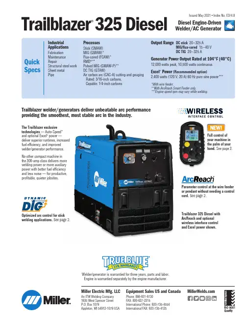
Trailblazer ®325 DieselDiesel Engine-Driven Welder/AC GeneratorIssued May 2021 • Index No. ED/4.8Welder/generator is warrantied for three years, parts and labor. Engine is warrantied separately by the engine manufacturer.Trailblazer 325 Diesel with ArcReach and optional wireless interface control and Excel power shown.The Trailblazer exclusive technologies — Auto-Speed ™ and optional Excel ™ power —deliver superior runtimes, increased fuel efficiency, and improved welder/generator performance. No other compact machine in the 300-amp class delivers more welding power or more auxiliary power with better fuel efficiency and less noise — for productive, profitable, quieter jobsites.Parameter control at the wire feeder or pendant without needing a control cord. See page 2.Trailblazer welder/generators deliver unbeatable arc performance providing the smoothest, most stable arc in the industry.Miller Electric Mfg. LLCAn ITW Welding Company 1635 West Spencer Street P.O. Box 1079Appleton, WI 54912-1079 USAEquipment Sales US and CanadaPhone: 866-931-9730 FAX: 800-637-2315International Phone: 920-735-4554 International FAX: 920-735-4125Optimized arc control for stick welding applications. See page 2.Full control of your machine in the palm of your hand. See page 2.2Trailblazer ®TechnologiesExcel ™ power (option)Power at idle — a Miller exclusive. Unlike competitive machines that provide auxiliary power only at 3,600 rpm (max), Excel power delivers a full 2,400 watts (20 A) of 120-volt inverter-based, pure sine-wave power at 2,400 rpm. With Excel power you can operate jobsite tools like grinders at quiet, fuel-saving speeds.Refueling time and operating costs are reduced with Excel power, which means more productivity and profitability. Plus everyone on the jobsite gets a better working environment because noise levels and exhaust emissions are lowered. Excel power — available only from Miller.Dynamic DIG ™ technologyUltra-adaptive arc control. Unlike conventional DIG that provides a preset amount of short-clearing current, Miller-exclusive Dynamic DIG technology works on a time-based algorithm that automaticallyadjusts the amount of current required to clear a short. Delivers asmoother more consistent arc that can be tailored to match application, material, fit-up and welder technique.Based on generator-only use for total runtime.Auto-Speed ™technologyMatches engine speed to load — a Miller exclusive. Get the welding power you need — plus reduced fuel consumption and lower noise levels for a more profitable jobsite.Auto-Speed technology responds to weld requirements by automatically adjusting engine speed to one of five rpm levels so the engine never works harder than necessary. Weld up to 135 amps while the engine remains at idle (1,800 rpm), saving up to 15 percent in fuel over competitive units, and drastically reducing jobsite noise.1,800RPMWelding below135 A2,400RPM2,800RPM3,600RPMWelding between 136–180 AWelding above235 AWelding between 181–210 A3,200RPMWelding between 211–235 AAuto-Speed in XX18 and TIG modes.Wireless interface control (option)Get full control of your machine in the palm of your hand so you can work hassle free.With wireless interface control, you can change welding processes, adjust parameters, select and save preset programs, turn the machine on/off, get service reminders and more from wherever you are on the jobsite. Extend time between fill ups and maintenance intervals while eliminating the need to go back to your machine to make adjustments.Wireless interface control is a factory-installed option available on the Trailblazer 325 Diesel.VIEW STATUSView engine status, fuel level, and battery charge level of remote.SELECT PROCESSESView and select between all available processes.CONTACTOR ON/OFF Turn contactor on/off manually in remote welding mode. CUSTOM PROGRAMSSave custom presets in up to four programs and easily switch between pre-programmed settings.FINE-TUNE ARCQuickly adjust and save arc control settings including DIG, DIG range inductance and Auto-Stop.AMP/VOLT ADJUSTAdjust amperage or voltage, by increments or percentage, while welding.ENGINE ON/OFFTurn engine on/off with remote.ArcReach ® technologyParameter control at the wire feeder or pendant without needing a control cord.An ArcReach system allows you to change weld settings from yourArcReach feeder or stick/TIG remote, saving a trip to the power supply.ArcReach technology uses the existing weld cable to communicate welding control information between the feeder or stick/TIG remote and the power source. This technology eliminates the need for control cords, and their associated problems and costs.3Quieter jobsitesQuieter jobsites are more productive because work crews can communicate easier, and work can start earlier and end later —even in noise-sensitive areas. Miller-exclusive Auto-Speed technology makes this welder/generator the quietest Trailblazer diesel yet — rated at 70 db at idle (1,800 rpm). If your jobsite needs a welder/generator, it needs a Trailblazer welder/generator — because no other diesel-fueled choice in this category is as quiet.Optional wireless interface control makes it easy to shut off the machine remotely when it’s not in use, so you can lower noise levels and hear what’s going on around you.More portable, uses less truck and jobsite spaceTrailblazer welder/generators use up to 24 percent less cubic space and weigh up to 10 percent less than other welder/generators in their class — which means moving them is faster and easier, for maximum productivity. And because they take up less space, Trailblazer welder/ generators let work trucks carry more equipment and gear — so your work crews can be ready for anything.Fewer refueling tripsNo other diesel welder/generator in the 300-amp class lets your crews spend more time working and less time refueling — because onlyTrailblazer welder/generators provide Auto-Speed ™ technology, plus the Excel ™ power option, to deliver maximum runtime.With optional wireless interface control, you can instantly turn your machine off when needed to save you even more fuel.Maximum cost savingsLess money spent on fuel means more profit for you. Every Trailblazer welder/generator has fuel-saving Auto-Speed technology; add optional Excel power to save even more on fuel costs and enjoy a combination of advanced, profit-enhancing features that are only available on a Trailblazer welder/generator.Maximize your savings with optional wireless interface control which allows you to turn your machine off remotely, saving you more money on fuel.Trailblazer ®BenefitsUnbeatable arc performanceWide amperage output with better welding deposition rates means you can get jobs done faster, saving time and money. The Trailblazer also has precise arc control, which allows you to fine-tune the arc to match yourpersonal preferences and quickly dial in the perfect parameters to optimize weld quality and maximize productivity across a variety of applications and welding processes.4Auxiliary Power Fuel ConsumptionU .S . G a l./h o u rWatts at 100% Duty Cycle00.500.251.000.751.501.251.752.000501001502002503003500.250.500.751.001.251.50DC Weld Amperes at 100% Duty CycleU .S . G a l./h o u rWeld Fuel Consumption*Idle*Fuel curve was generated using NEMA recommended voltage/amperage levels.Welding Mode CC/DC CV/DCProcess Stick/TIGMIG/FCAWRated Weld Output at 104°F (40°C)* 325 A at 33 V, 100% duty cycle325 A at 33 V, 100% duty cycleAmp/Volt Ranges 20–325 A 15–40 VSingle-Phase Generator Power Peak12,000 watts Continuous 10,500 wattsExcel ™ power (optional) 2,400 watts,20 A at 120 V, 60 Hz pure generator power at 2,400 rpm and while weldingSound Levels at 7 m (23 ft.) Weld135 A load: 70 dB (94 Lwa), 325 A load: 81.5 dB (106.5 Lwa) Generator powerExcel power (optional): 75 dB (100 Lwa),12 kW standard power: 81.5 dB (106.5 Lwa)NetWeight** 620 lb. (281 kg)DimensionsH: 28 in. (711 mm) H: 34.375 in. (873 mm) (to top of exhaust) W:20 in. (508 mm) D: 45.375 in. (1,153 mm)*Rated at sea level. **Net weight without fuel.Engine Specifications (Engines warrantied separately by the engine manufacturer.)A.20 in. (508 mm)B.16.5 in. (419 mm)C.1.75 in. (44 mm)D.6.062 in. (154 mm)E.32.75 in. (832 mm)F.45.375 in. (1,153 mm)G..406 in. (10.3 mm) diameterCertified by Canadian Standards Association to both the Canadian and U.S. Standards.Performance DataMounting SpecificationsE n g i n e E n d5Function and Benefit Guide23110891145 1.Self-calibrating digital meters with SunVision ™• Preset and actual amperage/voltage • Process settings• Maintenance functions: hour meter, oil change interval, rpm 2.Weld process selection switch 3.Pushbutton main control knob used for adjusting amperage/voltage, adjusting arc control, and accessing the service menu. 4.Adjustable arc control adjusts DIG when process control is in stick modes and adjusts inductance when process control is in FCAW or MIG modes. The amount of DIG determines how much amperage (heat) varies with stick arc length. Inductance determines the “wetness” of the weld puddle. 5.Maintenance interval reminder. Yellow and red indicator lights let an operator know when the machine is approaching, and finally in need of routine maintenance.6.Front-panel fuel-gauge LEDs indicate fuel level. Low fuel shutdown automaticallydetects and shuts engine off prior to running out of fuel. 7.Standard 14-pin receptacle for simple connection of remote controls and wire feeders. Includes Auto Remote Sense ™ which automatically switches from panel to remote amperage/voltage (A/V) control with remote connected. Eliminates confusion of a panel/remote switch. B port allows software updates from a USB drive. A summary file of recorded data from the unit will be saved to a USB drive that is inserted. 9.Engine control. Run/idle position adjusts engine to run at lower speeds depending on total power needed for welding. 10.Glow plugs assist in cold weather starting. 11.Weld output terminals12.Optional Excel ™ power (factory option,see page 8) provides pure generator power at 2,400 rpm and while welding.Note: If Trailblazer is ordered without Excel poweroption, unit is shipped with two 20 A, 120 V duplex receptacles with circuit breakers and ground fault.13.50 A, 120/240 V receptacle withcircuit breakerNote: For matching plug, order 119172.Genuine Miller® Options *Available as factory option. See ordering information on back page.GFCI Receptacles* 300975 FieldKit contains two GFCI 120 V duplex receptacles. (240 V GFCI receptacle not required.)Cold Weather Kit 301115 FieldIncludes block heater for improved starting, and a fuel heater for optimal filtration in cold temperatures.Spark Arrestor 043579 Field Mandatory when operating on California grass -lands, brush or forest-covered land, and all national forests. For other areas, check your state and local laws.Full KVA Adapter Cord 300517NEMA 14-50P to NEMA 6-50R. Adapts enginedrive 120/240 V plug to common Millermatic®and Spectrum® 240 V plug.Full KVA Plug Kit119172 Field120/240 V, 50 A plug(NEMA 14-50P) to fit fullKVA receptacle.Diesel Engine Filter Kit 259935 FieldIncludes air filter, oil filter, fuel pre-filter andprimary fuel filter.FemaleReceptacleGenuine Miller® AccessoriesNever Flat™ Tires Available on Bobcat and Trailblazer running gear. •Reduce costly jobsitedowntime•Maintain constant tire pressure and willnot develop flats•Protect against punctures•Preserve maneuverability, even whenweighed down with heavy welding cableAll-Purpose Running Gear 300477Includes two heavy-duty 15-inch Never Flat™tires, two 8-inch rubber swivel casters and aheavy-duty handle. Recommended for all surfacesand applications, and is easy to move aroundthe jobsite.Protective Cage with Cable Holders 195331Rugged cage with cable holders protects yourinvestment. Can be used with running gear,gas cylinder mounting assembly, or with trailer.Note: Not for use with protective cover.Protective Cover 301099Heavy-duty, water-resistant and mildew-resistant cover protects and maintains the finishof the welder.Wireless Interface Control Protective Covers287594Five-pack of screen protectors for wirelessinterface control remote.MIG/Flux-cored WeldingArcReach® SuitCase® 8951726 With Bernard® BTB Gun 300 A951727 With Bernard® S-Gun™951728 With Bernard® Dura-Flux™ gunArcReach® SuitCase® 12951729 With Bernard® BTB Gun 300 A951730 With Bernard® S-Gun™951731 With Bernard® Dura-Flux™ gunArcReach® SuitCase® 12 Heavy Duty301604Feeder only — for 3/32-inch cored wirePortable feeder designed to run off of arc voltage.When paired with an ArcReach power source,provides remote control of the power sourcewithout a control cord — saving time and money.See literature M/6.55.ArcReach® SmartFeeder 951733For use withArcReach modelsonly (see page 2 formore information).Includes drive rollsand Bernard®PipeWorx 300-15 MIGgun. For MIG, FCAW,and advanced RMD®and pulse processes. See literature M/6.55.SuitCase® 12RCWire Feeder 951580Lightweight andflexible enough to runwires up to .062-inchdiameter. Includesremote voltage control,drive roll kit andBernard® BTB Gun 300 A. See literature M/6.5.Spoolmatic® 30A Spool Gun 130831Air-cooled, 200-amp, one-pound spool gun foraluminum MIG. See literature M/1.73. RequiresWC-24 Control 137549.XR™ Wire Feeders and GunsPush-pull system designed to handle difficult-to-feed soft alloy wires such as aluminum.See literature M/1.7 through M/1.74.67Stick (SMAW) WeldingWeld Leads2/0 Stick Cable Set, 50 ft. (15 m) 173851 Consists of 50-foot (15 m) 2/0 electrode cable with holder, and 50-foot (15 m) work cable with clamp. 350 A, 100% duty cycle.2/0 Stick Cable Set, 100/50 ft. (30.5/15 m) 043952Consists of 100-foot (30.5 m) 2/0 electrode cable with holder, and 50-foot (15 m) work cable with clamp. 300 A, 100% duty cycle.AC TIG (GTAW) WeldingDynasty ® 210 Series For portable AC/DC TIG. See literature AD/4.81.Plasma CuttingSpectrum 375 X-TREME and 625 X-TREME shown.Spectrum ® 375 X-TREME ™ 907529 See literature PC/9.2.Spectrum ® 625 X-TREME ™ 907579 See literature PC/9.6. Spectrum ® 875 907583 See literature PC/9.8.The Spectrum 375 X-TREME and 625 X-TREME come complete with protective X-CASE ™ (not shown).Remote SolutionsArcReach ® Stick/TIG Remote 301325 When paired with an ArcReach power source, provides remote control of the power source without a control cord — saving timeand money. See literature AY/14.5.Wireless Remote Hand Control 301582For remote current, voltage and contactor control. Receiver plugs directly into the 14-pin receptacle of Miller machine. Up to 300-foot (91.4 m) operating range.RHC-14 Hand Control 242211020Miniature hand control for remote current and contactor control. Dimensions: 4 x 4 x 3.25 inches (102 x 102 x 82 mm).Includes 20-foot (6 m) cord and 14-pin plug. PRHC-14 Hand Control 195511Complete current or voltage control brings 120 volts GFCI power to work area in a single cord. Housed in a durable, light aluminum caseand includes 125-foot (38 m) cord with plugs. Extension Cables for 14-Pin Remote Controls 242208025 25 ft. (7.6 m) 242208050 50 ft. (15.2 m) 242208080 80 ft. (24.4 m)Remote Output Panel Kit 951850If your welder/generator is mounted on a truck, easily locate the outputs at the point of use with the auxiliary power and weld output remotepanel. See literature AY/20.5.Genuine Miller ®Accessories (Continued)HWY-Mid Frame Trailer 3014381,424-pound (646 kg) capacity highway trailer with welded steel tubing frame, heavy-duty axle with roller bearing hubs and leaf-spring suspension. Includes jack stand, fenders, lights, and dual hitch with 2-inch (50 mm) ball hitch and 3-inch (76 mm) lunette eye.Cable Tree 043826 Provides an area to conveniently wrap weld cables and extension cords.2-In-1 Document/Fire Extinguisher Holder 301236Stores documents and holds a five-pound fire extinguisher.Note: Holder shown mounted on trailer. Fire extinguisher not included.Trailers and Hitches (Note: Trailers are shipped unassembled.)Trailer Specifications (Subject to change without notice.)*Width at outside of fenders.Ordering InformationEquipment and Options Stock No. Description Qty. Price Trailblazer® 325 Diesel907799Base model(Kubota engine) 907799001With GFCI receptacles907799002With Excel™ power and GFCI receptacles907799003With Excel™ power, GFCI receptacles and wireless interface controlField Options Options listed below can be added to the above packages. Installation is required.GFCI Receptacles300975Cold Weather Kit301115Spark Arrestor 043579Full KVA Adapter Cord 300517Full KVA Plug119172Diesel Engine Filter Kit 259935AccessoriesAll-Purpose Running Gear 300477With Never Flat™ tiresProtective Cage with Cable Holders 195331Not for use with protective coverProtective Cover 301099Wireless Interface Control Protective Covers287594Five-pack of screen protectors for wireless interface control remoteMIG/Flux-cored WeldingArcReach® SuitCase® 8 951726With Bernard® BTB Gun 300 A951727With Bernard® S-Gun™951728With Bernard® Dura-Flux™ gunArcReach® SuitCase® 12 951729With Bernard® BTB Gun 300 A951730With Bernard® S-Gun™951731With Bernard® Dura-Flux™ gunArcReach® SuitCase® 12 Heavy Duty301604Feeder only — for 3/32-inch cored wireArcReach® Smart Feeder 951733For use with ArcReach models only. MIG/FCAW/RMD®/pulse feeder withBernard® PipeWorx 300-15 MIG gun. Tweco®-style connectorsSuitCase® 12RC 951580With Bernard® BTB Gun 300 A. See literature M/6.5Spoolmatic® 30A Spool Gun130831 Requires WC-24 control. See literature M/1.73WC-24 Control137549See literature M/1.73XR™ Wire Feeder Control and Guns See literature M/1.7 through M/1.74Stick Welding See page 7TIG Welding See page 7Plasma Cutting See page 7Remote Solutions and Extension CablesArcReach® Stick/TIG Remote301325For use with ArcReach models onlyWireless Remote Hand Control301582RHC-14 Hand Control 242211020PRHC-14 Hand Control195511Extension Cables See page 7Remote Output Panel Kit 951850For truck mounted welder/generators. Includes auxiliary power andweld output remote panelTrailers and HitchesHWY-Mid Frame Trailer 301438Trailer with lights, fenders and dual hitch. For highway useCable Tree043826Trailer-mounted cable holder2-In-1 Document/Fire Extinguisher Holder 301236 Stores documents and holds a five-pound fire extinguisherDate: Total Quoted Price:Distributed by:©2021 Miller Electric Mfg. LLC。

ENGINE ROOM™ LVL 12Hvala, da ste se odločili za nakup napajal-nika Engine Room LVL 12. Ta model vašiverigi učinkov zagotovi potrebno energijona stilski način, zasnovan za prvovrstnomoč, po zaslugi dvanajstih proti zemljiizoliranih izhodov (2 z napetostjo poizbiri), priključkov USB-A in USB-C zapriključitev pametnih naprav ter drugihsodobnih tehnologij vam ponudi najvišjeudobje. Če hrepenite po urejeni in učinko-viti razporeditvi svojih učinkov, izberitenapravo Engine Room.1. Izhod, Izoliran Proti Zemlji (Fiksen)Deset fiksno izoliranih izhodov 9VDC s 500mA.2. LED Stanja na IzhodihDve dvobarvni kontrolni lučki stanja tokovnega izhoda. Zelena kaže tok v okviru specifikacij, rdeča kaže trenutno preobremenitev.3. Izhod z Napetostjo po IzbiriDva izolirana izhoda z napetostjo po izbiri(9V/12V/18V), ki uporabljata trismerno stikalo.4. Stikalo Izhoda Napetosti po IzbiriDve trismerni stikali; eno za vsak izhod napajalnenapetosti po izbiri (9V / 12V / 18V).5. Izhod USB-AUSB-A izhod za polnjenjehitrih naprav.6. Izhod USB-CUSB-A izhod za polnjenjehitrih naprav.7. IEC Napajalni IzhodZa …veriženje“ z drugo združljivo napravo s pomočjo priloženega 12” kabla IEC tip moški/ženska.8. IEC Napajalni Vhod100V-240V omrežno napajanje, za uporabo kjerkoli po svetu.ENGINE ROOM™ LVL 12 SET KABLOV/DODATKINapajalnik ENGINE ROOM LVL 12 se dobavlja s setom kablov / dodatki, ki vsebuje različne kable, vključno s:• 6 X 24” (60cm) kabel, 2.1mm sodčkasti napajalni priključek• 4 X 18” (45cm) kabel, 2.1mm sodčkasti napajalni priključek• 2 X 12” (30cm) kabel, 2.1mm sodčkasti napajalni priključek• 18” (45cm) kabel, 2.5mm-2.1mm sodčkasti napajalni priključek (zelena)• 18” (45cm) kabel, 2.5mm-2.1mm sodčkasti napajalni priključek, obratna polarnost (rdeča)• 18” (45cm) kabel, 3.5mm TS-2.1mm sodčkasti napajalni priključek• 18” (45cm) kabel, nosilec baterije -2.1mm napajalni priključek• 12” (30cm) IEC kabel tipa "daisy-chain" v izvedbi moški-ženska• 78.7” (2m) IEC omrežni napajalni kabel• Štiri samolepilne gumijaste nogiceTIPFIKSNI IZHODI NASTAVLJIVI IZHODI POLNILNI USB IZHODIDIMENZIJETEŽA PR58979V 500mA9V 500mA, 12V 375mA, 18V 250mAUSB-A: 12WUSB-C: 18WŠirina: 11.1” (282mm) Višina: 1.65” (42mm) Globina: 3.66” (93mm) 835gSpecifikacije izdelka se lahko spremenijo brez predhodnega obvestila.IZDELEK DRUŽBEFENDER MUSICAL INSTRUMENTS CORPORATIONCORONA, CALIF. U.S.A.Fender® je zaščitena blagovna znamka družbe FMIC.Copyright © 2021 FMIC. Vse pravice pridržane.PN 7720281000 REV. APriročnik, dostopen v drugih jezikih, boste našli na naslovu/support。
KONGSBERG STEERING GEARRV / IRV series - the compact solution forlarger vessels. The proven technology preferred by leading owners since 1952, on more than 25 000 shipsHighly reliable power packsThe use of reliable power units is of vital importance for a vessel’s safety, and great care has been taken from material selection through construction in order to meet the strictest quality demands. Kongsberg Maritime dual pump power packs are designed with ship safety in mind, and with an eye to simplify the layout. This is achieved by removing the need for expansion tank and for a separate oil storage tank. The pumps are low noise, submerged, fixed displacement screw pumps that provide maximum reliability for an essential ship equipment.Built-in storage tankBuilt-in storage tank is an option that has gained a popular support amongmost yards and owners. This solution reduces space, saves installationtime and costs, and gives a clean layout in the steering gear room.Modulated flow controlThe control system modulates the oil flow to the actuator in order to give a soft start and low rudder speed for small rudder movements. The oil flow gradually increases up to full flow, allowing full turning speed on the rudder.The reduced flow ensures a very precise rudder positioning for small rudder angles, while the full flow provides for full manoeuvring force when needed. In this way the simple and reliable fixed displacement pump is efficiently controlled to provide smooth and accurate steering in line with a variable displacement pump, however, without introducing the complexity of such a pump.The precise rudder positioning makes Modulated Flow Control ideal incombination with autopilots, as the risk of rudder overshooting is minimised. This again makes course keeping easier, thus contributing to improve a ship’s propulsive efficiency.Starter systemThe new starter system with frequency converter interfaced with the emergency switch board, reduces the power and starting current requirements from the emergency generator to a minimum.Maintenance and overhaulBy splitting all internal seals and bearings and using an internal `lifting device´, the 4-vane steering gear can be totally overhauled without removing the rudderstock connection.Fact sheet available for related products• Alarm system• Rudder angle indicator system• Steering control system• Interface to external equipment4 - Vane technologyIllustration showing installation by stoppers and standard stud bolts2 &3 - Vane technologyIllustration showing installation by reamer boltsSG TYPEMAX. STOCK DIA (MM)MAX. WORKING PRESSURE MAX. WORKING TORQUE (KNM)MAX. RUDDER ANGLE WEIGHT APPROX (KG)MAX. RADIAL LOAD (KN)MAX. AXIALLOAD (KN)RV 700-24108060471.550001800700RV 850-34208079746.537001400500RV 900-24508079671.560001800700RV 1050-34508094046.550001800700RV 1100-25108094971.5800030001250RV 1350-349580122946.560001800700RV 1400-250080132171.581001800700RV 1650-355080149946.5800030001250RV 1700-256080155171.51100030001250RV 2050-2*58080186471.51200030001250RV 2300-4*580170230036.5100007001050RV 2600-362080240146.51150030001250RV 2700-2*65080248871.51500030001250RV 3050-366080287046.51200030001250RV 3500-4*670170350036.5140009001200RV 4000-370080380746.51500030001250RV 3050-2*70080279671.52000030001800RV 4200-2*73080391671.52400030001800RV 5000-4*750170500036.52000011001750RV 6000-4*800170600036.52300012502000Installation• Low weight, typically 50% less than RAM-type • Installation with reamer bolts or stoppers • Few components:• Integrated storage tank • Integrated rudder carrier • No expansion tank• No external grease pump requiredSafety• –Safety first through simple and reliable system • No external moving parts • Automatic lock valve • No external oil leakages• Double hydraulic sealing system on IMO type steering gearOperation• Modulated flow control valve ensures:• Smooth rudder movements• Rudder positioning better than proportional valves• Low noise level (80-85 dB A)• Polymer sealing ensure superior tightness of < 1°/min.Maintenance• No external lubrication required, internal bearings are lubricated by the hydraulic oil • Seals and bearings interchangeable without loosening the rudderstock connection • Short lead time on spare parts • World wide service• Low maintenance cost due to simplicity of the systemSwitchboard: +47 815 73 700Global support 24/7: +47 33 03 24 07E-mailsales:*********************.com E-mailsupport:***********************.comKongsberg Maritime P.O.Box 483, NO-3601Kongsberg, Norway。
APPLICATION: Telehandlers: MF 25T (LJ31191);Wheel Tractors: MF 60HX (LJ31231);QTY ITEM # DESCRIPTION LETTERED ITEMSINCLUDED IN KIT1 974184 In-Frame Kit I1 975184 Out-of-Frame Kit O1 976184 Major Kit M1 977184 Premium Kit (979142 Valve Train Kit Included) P4 4 4 4 4 4 171125 171227 171274 171131 171361 171468 Sleeve & Piston Asb (Piston Stamped "KS") (1) Piston Asb, Thru U424723U (Piston Stamped "KS") (1) (2)Piston Asb, After U424723U (Piston Stamped "ML") (1) (3)Liner (Finished / No Fire Dam / 4.103" OD) (4)Liner (Semi-Finished / No Fire Dam / 4.105" OD) (5)005 Liner ShimP M O I4 171272 Piston Ring Set (1-1/8K 1-3/32 1-3/16)4 4 4 4 271261 271262 271263 271264 STD Rod Bearing .010 Rod Bearing.020 Rod Bearing.030 Rod BearingP M O I1 1 1 1 271161 271162 271163 271164 STD Main Set, wo/Thrust Washers .010 Main Set, wo/Thrust Washers.020 Main Set, wo/Thrust Washers.030 Main Set, wo/Thrust WashersP M O I1 1 1 271119 271125 271126 STD Thrust Washer Set .007 Thrust Washer Set.010 Thrust Washer SetP M O I1 1 1 8 8 4 371321 371132 371117 371143 371192 371318 Head Gasket Set Head GasketValve Cover GasketValve Seal (Umbrella)Valve Seal (O-Ring)Nozzle Dust Seal Kit "Not In Sets Or Kits"P M O I1 1 1 1 1 371292 371149 371235 371167 371282 Lower Gasket Set wo/Seals Timing Cover Gasket Fuel Line Seal Kit (23 Seals & Washers) "Not In Gkt Sets" Pan Gasket Set, Cast Pan (Includes 6 Oil Flange Gaskets) Pan Gasket, Steel Pan P P M M O OII1 1 1 371146 371145 771159 Front Crank Seal (Viton Lip Type) (7) Rear Crank Seal (Viton Lip Type) (8) Rear Block Bridge PieceP P M M O O4 1 4 271135 271127 771171 Pin Bushing (1.500" Pin) Cam Bearing (Finished ID) Balancer Weight BushingsP P M M8 8 1 771151 771148 771293 Connecting Rod Bolt Connecting Rod Nut Head Bolt Kit (Ribbed Blocks / .500" CB)P P MM(1)ML&KS pistons are different weights, replace in sets, DO NOT MIX (2)Untopped KS Piston-171415 (3)Untopped ML Piston-171416APPLICATION: Telehandlers: MF 25T (LJ31191);Wheel Tractors: MF 60HX (LJ31231);QTY ITEM # DESCRIPTION LETTERED ITEMSINCLUDED IN KIT1 979521 Camshaft Kit C1 979142 Valve Train Kit V1 1 8 571134 271249 571123 Camshaft "Cam Bolt Lock Plate - 571162" Camshaft Thrust Washer (1.750 X 2.873 X .217) (10) Tappet CC4 4 471123 471135 STD Exhaust Valve (45º / Bi-Metal / Chromed Stem) STD Intake Valve (30º / Alloy / Chromed Stem) V V4 471132 Exhaust Guide V4 471131 Intake Guide V8 471134 Outer Valve Spring (8 Coils / 2.5" Free Length) V8 471133 Inner Valve Spring (9 Coils / 2.0" Free Length) V8 471229 Spring Seat (Stepped/.640" ID)8 471222 Spring Retainer16 471146 Keeper (Half) V4 471111 Exhaust Seat (1.248 x 1.681 x .374 Stepped Top)4 471224 LH Rocker Arm (Adj Screw & Lock Nut Not Included) (11)4 471225 RH Rocker Arm (Adj Screw & Lock Nut Not Included) (11)1 471227 Rocker Arm Shaft (12) "Includes 471176 Plugs"1 571171 Cam Gear (Steel / 56 Teeth)1 571113 Crank Gear (28 Teeth) 1 571163 Idler Gear (Steel / 63 Teeth) (13)1 571145 Idler Gear Hub8 571117 Push Rod1 671142 Oil Pump Kit (Gears,Shaft,Plate,Valve,Spring,Cap,Gkts)1 671143 Oil Pump Body, w/LH Oil Filter (Cast Gear Housing)1 671146 Oil Pump Inlet Strainer4 671157 Piston Cooling Jet4 671158 Piston Cooling Check Valve1 671149 Oil Cooler1 771181 Crank Kit (Spline Nose / Lip Seal)4 771194 Connecting Rod (1.500" Pin)1 771317 Cylinder Head Assembly (Includes Valves & Springs)1 771164 Balancer Assembly, Engines w/LH Oil Filter (Incls Oil Pump)1 771165 Balancer Kit (3-Shafts 2-Gears 2-Keys 4-Brgs)2 771197 Balancer Gear (3 Bolt / 1.375 ID / 30T)1 771286 Expansion Plug Kit: Thru U280718S (19 Head&Block Plugs)1 771294 Expansion Plug Kit: After U280718S (20 Head&Block Plugs)1 871138 Thermostat (2.125" / Bypass)1 871229 Water Pump wo/Pulley1 871228 Block Heater (1.250")1 871182 Manifold Heater Plug (Blade Terminal)1 871226 Fuel Pump (4 Bolt / One Port Toward Block)(10)U729165B-U732690B Uses 271239 (1.750 X 2.873 X .243 Recessed Face) (11)Adj Screw - 471226 / Lock Nut - 571139。
RATINGS 400V - 50 Hz kVA800Standby KWe640kVA727Prime KWe582Alternator commercial brand KOHLER Voltage (V)400/230Performance classG3One step load acceptance (out of ISOcriteria)100%Standard Control Panel M80-D, APM403, APM802,TELYSGenset Fuel consumptionPRP ESP Consumption @ 100% PRP load (L/h)150,10163,50Engine optimisation E Type of CoolingRadiatorStandby RatingPrime Rating VoltagePHHzkWekVAAmpskWekVA415/2403506408001113582727 400/2303506408001155582727 KD800-E380/2203506408001216582727Data Center Continuous (DCP) Power rating is the same as the prime rating when a reliable grid is availableBenefits & featuresKOHLER SDMO premium quality▪KOHLER SDMO provides one source responsibility forthe generating system and accessories ▪The generator set, its components and a wide range ofoptions have been fully developed, prototype tested, factory built , and production-tested ▪The generator sets are designed in accordance toISO8528-5 performance class G3 and accepts rated load in one stepKOHLER SDMO premium performances Engines▪Low fuel consumption thanks to a high technologycommon rail injection engine ▪ A smaller footprint thanks to a high power density ▪Low temperature starting capability ▪Long maintenance interval Alternator▪Provide industry leading motor starting capability ▪Excitation system to permit sustained overcurrent >300% In, during 10 sec ▪Built with a class H insulation and IP23Cooling▪ A compact and complete solution using a mechanicallydriven radiator fan ▪High temperature and altitude product capacity, runningwithout power derating up to 50°CControl PanelThe KOHLER SDMO wide controller range provide the reliabilityand performances you expect from your equipment. You can program, manage and diagnose it easily and in an efficient way KOHLER SDMO worldwide support▪ A standard three-year or 1000-hour limited warranty forstandby applications. ▪ A standard two-year or 8700-hour limited warranty forprime power applications.▪ A worldwide product supportPOWER RATINGS DEFINITION : according to ISO8528-1 (2018-02 edition) and ISO-3046-1Emergency Standby Power (ESP): The standby rating is applicable to varying loads for the duration of a power outage. There is no overload capability for this rating. Average load factor is <85%. Prime Power (PRP): At varying load, the number of generator set operating hours is unlimited. A 10% overload capacity is available for one hour within 12 hour of operation. Average load factor is<75%.Data Center Continuous Power (DCP): At varying or constant load, the number running hours is unlimited. 10% overload capacity is available for one hour within 12 hour of operation.For limited running time, continuous or other ratings details, consult your contact and obtain technical information for ratings guidelines, complete ratings definitions, and site condition derates.KOHLER DIESEL ENGINEGeneralEngine brand KOHLER Engine ref.KD27V12-5AES Distribution4TAir inlet system TurboFuel GO Engine optimisation E Cylinders configuration V Number of cylinders12 Displacement (L)26,97Bore (mm) * Stroke (mm)135 * 157 Compression ratio15 : 1 Speed (RPM)1500 Maximum stand-by power at rated RPM (kW)709 Cylinder Head Material Cast Iron Crankshaft Material Steel Intake and Exhaust Valve Material Steel Piston type & material Steel Charge Air coolant Air/Air DC Frequency regulation, steady state (%)+/- 0.25% Injection Type Direct Governor type Electronic ECU type KODECAir cleaner type, models DryFuel systemMaximum fuel pump flow (L/h)245Fuel Inlet Minimum recommended size (mm)19,05Fuel Outlet Minimum recommended size (mm)9,53 Max. restriction at fuel pump (m)3,50Max head on fuel return line (m)3,10 Maximum allowed inlet fuel temperature (°C)60 Consumption with cooling system PRP ESP Consumption @ 100% PRP load (L/h)150,10163,50 Consumption @ 75% PRP load (L/h)117,30127,10 Consumption @ 50% PRP load (L/h)83,8091,80 Consumption @ 25% load PRP (L/h)46,1050,10Lubrication SystemOil system capacity including filters (L)101 Min. oil pressure (bar)3,30 Max. oil pressure (bar)5,50Oil sump capacity (L)89Oil cooler Plate Exchanger Oil consumption 100% ESP (L/h)0,08Air Intake systemMax. intake restriction (mm H2O)510 Intake air flow (L/s)819,03 Exhaust systemHeat rejection to exhaust (kW)510PRP ESP Exhaust gas temperature (°C)472466 Exhaust gas flow (L/s)19852138 Max. exhaust back pressure (mm H2O)867 Radiator Charge Air Cooling SystemAmbiant temperature design (°C)40 Radiated heat to ambiant (kW)50 CAC Heat Rejection (kW)134 Heat rejection to coolant HT (kW)251 Radiator & Engine capacity (L)97 Coolant capacity HT, engine only (L)55 Flow on the HT circuit at 0.7Bars pressure drop offengine (L/min)823 Maximum Coolant temp without derating (°C)100 Outlet coolant temperature (°C)100 Type of coolant Gencool Compressor Discharge Temp at 25°C (°C)180 Thermostat begin of opening HT (°C)82 Thermostat end of opening HT (°C)92Fan power (kW)32Fan air flow w/o restriction (m3/s)18,40 Available restriction on air flow (mm H2O)20Alternator Specifications Alternator commercial brand KOHLER Alternator ref.KH03544TNumber of pole 4Number of bearing Single Bearing TechnologyBrushless Indication of protection IP23Insulation classH Number of wires12Capacity for maintaining short circuit at 3 ln for 10 s Yes AVR Regulation Yes Coupling DirectApplication data Overspeed (rpm)2250Power factor (Cos Phi)0,80Voltage regulation at established rating (+/- %)0,50Wave form : NEMA=TIF<40Wave form : CEI=FHT<2Total Harmonic Distortion in no-load DHT (%)2,5Total Harmonic Distortion, on linear load DHT (%)2,2Recovery time (Delta U = 20% transcient) (ms)200Performance datasContinuous Nominal Rating 40°C(kVA)750Unbalanced load acceptance ratio(%)100Peak motor starting (kVA) based on x% voltage dip power factor at 0.3Alternator Standard Features-All models are brushless, rotating-field alternators -NEMA MG1, IEEE, and ANSI standards compliance for temperature rise and motor starting-The AVR voltage regulator provides superior short circuit capability-Self-ventilated and dip proof construction-Sustained short-circuit current of up to 300% of the rated current for up to 10 seconds -Superior voltage waveformNote: See Alternator Data Sheets for alternator application data and ratings, efficiency curves, voltage dip with motor starting curves, and short circuit decrement curves.Dimensions compact versionLength (mm) * Width (mm) * Height (mm)4190* 1500 * 2275 Dry weight (kg)5470Tank capacity (L)500* Sounds level in dB(A) are given at 75% Prime Power Dimensions soundproofed versionM427SILength (mm) * Width (mm) * Height (mm)6413* 2160 * 2750 Dry weight (kg)8300Tank capacity (L)1035Acoustic pressure level @1m in dB(A)86Measured acoustic power level (Lwa)107,50 Acoustic pressure level @7m in dB(A)77* Sounds level in dB(A) are given at 75% Prime Power Dimensions super soundproofed versionM427SSILength (mm) * Width (mm) * Height (mm)6400* 2170 * 2750 Dry weight (kg)8500Tank capacity (L)1035Acoustic pressure level @1m in dB(A)82Measured acoustic power level (Lwa)103,20 Acoustic pressure level @7m in dB(A)73* Sounds level in dB(A) are given at 75% Prime PowerContener dimensions ISO20 versionISO20 SiLength (mm) * Width (mm) * Height (mm)6058* 2438 * 2896 Dry weight (kg)11210Tank capacity (L)500Acoustic pressure level @1m in dB(A)84Measured acoustic power level (Lwa)105Acoustic pressure level @7m in dB(A)75* Sounds level in dB(A) are given at 75% Prime PowerContener dimensions ISO20 super soundproofed versionLength (mm) * Width (mm) * Height (mm)9140* 2438 * 2896 Dry weight (kg)11800Tank capacity (L)500Acoustic pressure level @1m in dB(A)75Measured acoustic power level (Lwa)97Acoustic pressure level @7m in dB(A)66* Sounds level in dB(A) are given at 75% Prime PowerM80-DThe M80-D can be used as a basic terminal block for connecting an electrical cabinet box and as an instrument panel with a highly intuitive LCD screen giving an overview of your generating set's basic parameters:-Oil gauge -coolant temperature -oil temperature -engine speed -battery voltage -charge air temperature -fuel consumption -etc.The engine main functions can be controlled and events are recorded to facilitate diagnostics:-starting -speed adjustment -stopping -droop -etc.TELYSERGONOMIC AND USER FRIENDLY Large display screen, buttons and scroll wheel,Electrical measurements: voltmeter, frequency meter, ampmeter, voltage.Engine parameters: working hours counter, oil pressure, coolant temperature, fuel level, engine speed, batteryAlarms and faults: oil pressure, coolant temperature, failure to start, overspeed, alternator min/max., battery voltage min. /max., emergency stop, fuel level.Ergonomics: wheel for navigating around the various munication: remote control and operation software,USB connections, PC connection.For more information on the product and its options, please refer to the sales documentation.APM403BASIC GENERATING SET AND POWER PLANT CONTROLThe APM403 is a versatile control unit which allows operation in manual or automatic mode-Measurements : voltage and current -kW/kWh/kVA power meters -Standard specifications: Voltmeter, Frequency meter. -Optional : Battery ammeter.-J1939 CAN ECU engine control -Alarms and faults: Oil pressure, Coolant temperature, Overspeed, Start-up failure, alternator min/max, Emergency stop button.-Engine parameters: Fuel level, hour counter, battery voltage.-Optional (standard at 24V): Oil pressure, water temperature.-Event log/ Management of the last 300 genset events. -Mains and genset protection -Clock management -USB connections, USB Host and PC, -Communications : RS485 INTERFACE -ModBUS protocol /SNMP -Optional : Ethernet, GPRS, remote control, 3G, 4G,-Websupervisor, SMS, E-mailsAPM802ADVANCED POWER PLANT MANAGEMENT CONTROLDedicated to power plant management APM802 provides advanced control, system monitoring, and system diagnostics for optimum performance and compatibility-Graphic display with touchscreen-User language selectable-Specially researched ergonomics-High level of equipment availability-USB and Ethernet ports-Modbus protocol-Making it easy to extend the installation-Complies with the international standard IEC 61131-3STANDARD SCOPE OF SUPPLYAll our KD Series gensets are fitted with:-Industrial water cooled DIESEL engine-Radiator with coolant-Electric starter & charge alternator 24 V D.C-Electronic governor-Standard air filter-Single bearing alternator IP 23 T° rise/ insulation to class H/H-Welded steel base frame with 80% vibration attenuation mounts-Flexible fuel lines & lub oil drain pump-Fuel water separator filter-Exhaust outlet with flexible and flanges-M80 control panel-User’s manual (1 copy)-Packing under plastic film-Delivered with oil-Delivered with antifreeze liquidCODES AND STANDARDSEngine-generators set is designed and manufactured in facilities certified to standards ISO9001:2015 & ISO14001:2015. The generator sets and its components are prototype-tested, factory built and production tested and are in compliance with the relevant standards: -Machinery Directive 2006/42/EC of May 17th 2006-EMC Directive2014/30/UE-Safety objectives set out in the Low Voltage Directive 2014/35/UE-EN ISO 8528-13, EN 60034-1, EN 61000-6-1, EN 61000-6-2, EN 61000-6-3, EN 55011, EN 1679-1 et EN 60204-1TERMS OF USEAccording to the standard, the nominal power assigned by the genset is given for 25°C Air Intlet Temperature, of a barometric pressure of 100 kPA (100 m A.S.L), and 30 % relative humidity. For particular conditions in your installation, refer to the derating table.WARRANTY INFORMATIONSStandard Warranty Period:-for Products in "back-up" serviceo30 months from the date the Product leaves the plant, extended to 42 months for KD serieso24 months from the Product’s commissioning date, extended to 36 months for KD serieso1,000 running hoursThe warranty expires when one of the above conditions is met.-for Products in "continuous" service (continuous supply of electricity, either in the absence of any normal electricity grid or to complement the grid),o18 months from the date the Product leaves the plant, extended to 30 months for KD serieso12 months from the Product’s commissioning date, extended to 24 months for KD serieso2,500 running hours, extended to 8700 running hours for KD seriesThe warranty expires when one of the above conditions is met.For more details regarding conditions of application and scope of the warranty please refer to our General “terms & conditions of sales”.。
JIANGSU WINSUN POWER CO., LTDADD :NO.98,Jianghai Road, Economic Development Zone, Nantong, Jiangsu, ChinaTEL :+86-513-85105915 51018337 FAX :+86-513-85537397 Zip code :226008website :www. www. E-mail :sales@R2V/X Series Diesel EngineOperation ManualJIANGSU WINSUN POWER CO., LTDCONTENTSCHAPTER I: TO CUSTOMERS1. Operation manual2. Safety cautions3. Service manualCHAPTER II: DIESEL ENGINE OPERATION1. Technique specifications and data2. Operation for diesel engine3. Maintenance of diesel engine4. Storage of diesel engine5. Engine troubleshootingCHAPTER I: TO CUSTOMERSDear user, your name is recorded in our company’s user file. Following the precautions described in this manual will enable you to use this engine with compete satisfaction. Failure to observe any of the rules and precautions, however, may result in a scalding, injury, fire or engine damage and make the guarantee provided with engine become invalid. Read this manual carefully and be sure you fully understand it before beginning operation.1. Diesel engine operation1.1 A new engine must be properly broken in. For the first 20 hours, run the engine at low speed and low loads. Do not allow engine to run at high speed and high loads at se`1vere condition during the break in period.1.2 After the break in period, please retighten the nuts and bolts of cylinder head cover; adjust the valve clearance before run the engine at normal speed.1.3 Do operate and use the engine upon to the power and speed marked on name plate. Do not allow engine to run at overload, over speed or low load in long time.1.4. After starting the engine, run the engine for 3-5 minutes at low speed, zero-load, then gradually increase the speed and add the load.1.5. The worker should learn the engine well about the working principle and structure, check and maintain the engines regularly. Do troubleshoot the problem in time and not allow run the engine with problem or make the engine work without worker on duty for longtime.1.6. Use the diesel oil and engine oil specified in this operation manual. Clean and filter the diesel oil and engine oil before use and keep the oiler clean, change the engine oil regularly.1.7. Do maintain the air filter regularly, keep the sponge strainer clean and change the filter element when necessary.1.8. To serve you with better technique support, please fill in the Receipt Form for Buyers after purchase the engine,2. Safety precautions2.1. Do not allow persons who have no capacity like children, elders, and sick enter into the work place of diesel engine.2.2 Do not allow to operate the diesel engine when lose control on self like in bad heath or drink.2.3Check the fastening including the condition of each installation, connection and the hold down bolts and fasten them in time2.4 Exhaust precautions2. Safety precautions2.1. Do not allow persons who have no capacity like children, elders, and sick enter into the work place of diesel engine.2.2 Do not allow to operate the diesel engine when lose control on self like in bad heath or drink.2.3Check the fastening including the condition of each installation, connection and the hold down bolts and fasten them in time2.4 Exhaust precautions●Never inhale the exhaust gases; it contains carbon monoxides, acolorless, odorless and extremely dangerous gas which cancause unconsciousness or death.●Never operate the engine indoors or in a poorly ventilated area,such as tunnel or cave, etc.Exercise extreme care when operating the engine near people or animals. Keep the exhaust pipe free of external objects.2.5 Refueling precautions●Be sure to stop the engine before refueling.●Do not overfill the fuel tank●If fuel is spilled, wipe ii away carefully and wait until the fuel has driedbefore starting the engine again.●Check the fuel the type specified before fill fuel. If add other fuel likegasoline, it will make fire easily.●Make sure that there is no fire before refueling and keep the dieselengine from oil and other inflammable materials to avoid fire.●When changing oil, make sure that the fuel cap is tightly securedto prevent fuel leakage2.6 Fire precautions●Never operate the engine while smoking or near an open flame●Never use the engine around dry brush, twigs, cloth-rags, or otherflammable materials●Keep the engine at least 3 feet (1 meter) away from building orother structures●Keep the engine away from flammables and other hazardousmaterials2.7 Protective cover●Always place the protective covers over the rotating parts. Ifrotating parts such as the driving pulley, belts, and shafts areexposed, serious injuries can be caused. To prevent injury, pleaseequip all rotating parts with protective covers.●Be care of hot parts. The muffler and other engine parts canbecome very hot while the engine running or after the engine hasbeen run. Always operate the engine in a safe area and keepchildren away from running engines. 2.8 Check before operation●Carefully check fuel pipe and fuel joints for fuel leakage. Leakedfuel created a dangerous situation.●Verify that all the nuts and bolts of the engine are tights. A loosenut or bolts may cause serious engine failure and could lead toserious injuries.●Always check the engine oil and refill it if necessary.●Check the diesel fuel and refill it if necessary. Do not overfill thefuel.●Wear suitable work cloth when operate diesel engine.●Accident will happen for loosed apron, towel or leather belt maybe rolled by diesel engine2.9 Surroundings●Operate the engine on a table or level surface of small rocks andloose gravel.●Operate the engine on a level surface. If the engine is titled, fuelmay spill form the gas tank.★ATTENTION:Operating the engine at a steep incline may cause the engine to seize up due to improper lubrication even when the oil level is a maximum.●Be careful of the fuel spillage when transporting the engine.●Tighten the fuel cap can close the fuel strainer cock beforemoving the engine around.●Never move the engine while it is in operation.●If the engine will be transported over a long distance, drain all thefuel from the fuel tank to prevent fuel leakage.3. Service guide3.1 To serve users better with better technique support, please fill in the Receipt from Buyer carefully to send it back to Winsun to keep the information of buyers in record.Read the operation manual carefully and keep the Document for Three Guarantees and present effective invoice and the Document for Three Guarantees.The warranty period for diesel engine is one year or 1000 hours of accumulated running hour since the engine purchased.3.2 If you have any questions for operate the diesel engine, please contact your local dealer or us.3.3 Please note to place the warning mark in the conspicuous position and contact with local dealer to change new mark when the mark is off or unclear.3.4. We state here that: Winsun will not afford any responsibility for the problems caused by the unreasonable modification or operation of user. CHAPTER TWO: DIESEL ENGINE OPERATIONMANUAL1. Main technique data and specification for diesel engine1-2 Overall engine dimension and installation1-2.1 The diagram for diesel engine and installation dimensionFIG 1-1 Diagram for diesel engine X FIG 1-2 Dimensions for installation X FIG 1-3 Diagram for diesel engine (R2V820) FIG 1-2 Dimensions for installation (R2V820)1-2.2 Installation(1)there must be a tight stationary foundation for the diesel engine to avoid vibration or movement when the engine is running.(2)Make sure that the centering position of the output shaft is properly aligned(3)Verify that the dimension of the hole on the belt wheel and keyway shaft match or correspond with each other. Also make sure that the bolt of the engine shaft is tightened to the proper torque specification. (4)When the engine is matched with other belt driven machines, the total desired belt distance traveled by the driven wheel must equal the total distance traveled by the driven wheel. If this is not properly calculated and matched, the desired speed on the driven wheel will be incorrect. A formula used to calculate the necessary diameters of the various wheels is provided below.The diameter of driving wheel (belt wheel) can be calculates as follows:(5)The power output point allowable loadMaximum permissible radial load:Maximum permissible axial force:F2=1350NTransmitted torque: A :100%(6)Make sure that the belt has a correct tension to itIf the belt is too tight, the engine bearing will wear at a high rate leading to)(91)(520001N m m L F -=engine failure. If the belt is to loose, the belt will slip at high speeds and high loads causing high pitch whistling noises.1-2.3 Crankshaft driving angles must be less than 120 120°,( see Fig 1-3.)1-2.4 GradientsThe gradient must be kept within the allowed value shown on Fig1-4 (vertical shaft engine excluded)FIG. 1-3 FIG. 1-41.2.5 Please contact our dealers about electric circuits involved with this engine. We recommend the use of accumulator rates at 20 hours shown in table 1-1.Table 1-1 unit:AH1—3 Diesel engine connection dimension1—3.1Diesel engine shaft specificationSelect the suitable PTO shaft type when diesel engine is fitted with machines and equipments for reasonable matching.Below four types of PTO shaft for users to select (see fig 1-5) .We can design PTO shaft according to special applications to for users to match with machine better.Fig 1-5 Diesel engine shaft dimension1—3.2 Size of PTO flanges(shown in Fig1-6)Fig 1-6 size of PTO flange 1—4 Name of Diesel engine parts1-5 Port timing, fuel injection timing, valve clearance1-5.1 Port timing (see table 1-2)1—5.2 fuel supply advance angle (see table 1-3)1-5.3 Valve clearance(cold state)(see table 1-4)1-5) Table 1-51-7 Torque specification for main bolts and nuts (See table 1-6)2. DIESEL ENGINE OPERATION2—1 Please pay close attention for safe operation of the diesel engine(1)The fuel used must be filtered by silk fabric or settle for 24 hours before it is used in the engine. Never add oil to the crankcase when the engine is running.(2)Keep flammable and combustible goods away from engine while engine is running. The engine should be placed in a simple ventilated place. (3)Do not touch the muffler when the engine is running or just after it has stopped.(4)The diesel engine should be operated at its rated power and rated speed. If abnormal operating conditions are detected, stop the engine immediately to check and fix the problem.(5)A new engine must be properly broken in. For the first 20 hours, run the engine at low speed and low load. Do not allow engine to run at high speed and high loads during the break in period.2—2 Fuel choice and Preparation for start diesel engine2-3 Starting of the Diesel engine2-3.1 StartingA Set the fuel tank cock on the ―ON‖ position.B. Set the speed governor lever to the ―start‖ position.C. Turn the start switch clockwise to the ―Start‖ position.D. If the engine is started, immediately remove your hand away from the key switch.E. If the engine does not start after 10 seconds, wait for a while (about 15 S) before trying to start the engine again.2-3.2 BatteryElement for Air filter(plastic square type air filter):Do not wash the element of air filter, because this part is dry type. When power of engine is not good or the color of exhaust is abnormal, change the element. Do not operate the engine without element.Engine oil inlet :Place theengine on level ground and fill the engine oil into the inlet. When checking the oil level, gently place the dipstick into the oil. Turn and tighten the oil dipstick. 1. Lube oil qualityThe qualified lube oil should meet following condition: ACEA-B2/E2or higher-grade specificationAPI-CD/CE/CF-4/CG-4or higher-grade specification 2. Lube oil viscosity Select lube oil viscosity based on ambient temperature when starting at cold temperatureFuel tank cock OFFONA. Always check the liquid level of the battery every month, if the level is lowerthan the low limit mark, refill the battery with distilled water till you reach the upper limit mark.B. If the liquid level in the battery is too low, the electric starter will not functionto its best potential. Always keep the level of the liquid in the battery between the upper and lower limits.C. If there is too much liquid, the liquid will splash onto the other nearby partsthereby ruining the battery.2-4. Operating and stopping of the diesel engine 2-4.1 Operating the engine(1)Preheat the engine for three minutes at no load (2) Set the speed governor lever to the desired speedFuel controllerSpeed control screw2-4.2 Check on the engine while the engine running. (1) Check if there is abnormal noise or vibration.(2) Check to make sure there is good combustion or over speed running.(3)Check to see the color of the exhaust gases to see if it is too white or too black.If any of these conditions are detected, stop the engine immediately and contact your nearest dealer for repair information.2—4.3 Stopping the engine(1)First, bring down the speed of the engine by using the speed governor. Let it run for 3 minutes at no load before stopping it. Speed governor(3)Set the fuel tank cock T ―Stop‖ position.(4)If the engine comes with an electric starter, turn the starting switch to the ―Off‖ pos ition.When the engine need to stopped immediately for emergency situation like over speed, close the fuel tank cock and loosen the joint nut of high-pressure fuel pipe, then the engine will be stoppedimmediately.(For engine with electric solenoid, turn the key switch to the Stop position)2-5 Precaution for engine running and after stop2-5.1 Precaution for engine running(1) When the oil alarming red lamp is on, stop the engine and check the engine oil immediately(2) Check the fuel level regularly and refill in the fuel when fuel is insufficient(3) Clean the dirt in the opening of air induct and exhaust of diesel engine regularly(4) The engine is not allowed to run when it exhaust black smoke. If the parts of engine are normal but there is black smoke in the opening of exhaust, the engine should be used overload. For this problem, reduce the load.If the fault of engine, please stop the engine and examine and resolve the problem immediately.(5) Check whether there is abnormal noise of engine regularly. Stop andexamine the engine immediately.2-5.2 Precaution after stopping engineon theflywheel aimed at top dead center mark on air induct cover and valves of two cylinder closed to avoid dust enter into cylinder or corrode the potted line of valve.(2) Close the fuel cock and check the element of fuel filter is in good condition.(3) Make sure the fastening of engine base is stable and also the fastening of the bolts, nuts on engine and tighten them if they are loose.(4) When the engine will stored for long time, seal the engine with waterless engine oil.(5) Clean the dirt from the engine and put the engine in a nice dry noncorrosive place.3. TECHNICAL MAINTENCE OF DIESEL ENGINE3-1 Daily checks and maintenanceCheck the oil level of the engine to see whether it is between the upper and lower limits.Check to see whether there any oil leaks within the engine.Keep the engine clean by cleaning up the dirt and other greasy deposit on the engine.3—2 Regular checks and maintenanceRegular checks and maintenance are very important for normal operation and engine life. The following table indicates what is necessary to be performed at specific time intervals. The marks signify that a special tool or technique is needed for maintenance. Please3—3 Maintenance for diesel engineFirst period maintenanceAfter running for 150 hours, the diesel engine should be maintained for first period:1、Clean the air filter, make sure the paper core is good and check each tuck.2、Check and adjust the valve clearance3、Check the engine oil, change or refill engine oil.4、Check the engine oil quality. Change all the engine oil and clean the engine body and fuel pipeline after the engine running for 200 hours.Second period maintenance:It depends on the technique condition of diesel engine the second period maintenance.Within the period of three guarantees, the second period maintenance should be conducted with the appointed for below items, excluding the first period guarantees.1.Clean the pipeline of fuel tank, exhaust tube, muffler2.Clean the carbon deposit on the injection nozzle, piston, cylinder,cylinder head etc3.Check and adjust the fuel injection pressure, clearance for pistonrings, fuel delivery beginning.4.Check the tightness of valve and do grind the valve if leakageoccurs. 5.Check the fastening of connection rod, crankshaft, and flywheel etc.6.Trail running check.4. STROING THE DIESEL ENGINEPlease follow the instruction below if you plan on storing the engine for long periods of time to avoid corrosion and damage.4.1 Remove the oil-drain screw, drain off the engine oil and retighten the oil-drain screw quickly before the engine oil becomes cool when the engine is stopped.4.2. Drain off the diesel oil of fuel tank.4.3 Take out and clean the lube oil filter4.4 Remove the fuel injection pump and clean the inner side of cylinder body with clear diesel oil. Drain off the cleaning oil from the oil-drain screw.4.5 Clean the air filter and inner side. Remove the dirt on the opening of air inlet and exhaust.4.6 Dehydrate 1.8kg strained lubricating oil (Warm up it to 110-150℃till no bubbles). Fill 1kg dehydrated engine oil into the crankshaft case and turn the engine to make the lubrication system filled with engine oil.4.7 Then fill 0.3kg dehydrated engine oil into the air intake pipe, turn the diesel engine to make the engine oil onto the piston, cylinder head cover, valve line. Finally turn the flywheel to the position that both cylinder valves are closed to make the engine cavity insulated.4.8. Heat the left dehydrated engine oil with 0.2kg industrial Vaseline till they melt and mix together well.4.10 Packed the air cleaner and opening of exhaust with oilpaper toavoid dirt enter into engine. 4.11 Finally brush the mixed oil evenly onthe engine parts without paint like flywheel, fuel pipe etc.4.12 Do not allow brush oil on the parts of rubber and plastic.4.13 The engine should be stored in the well ventilated and dry placeand not allowed to store in the place with chemistryThe diesel engine can be well stored for six month by above methods.When it exceeds six month, the engine can be stored again with theinstruction.5. DIESEL ENGINE TROUBLE SHOOTING AND REMIDIES5-5 Diesel engine exhausting blue smoke5—7 Method and location of the inspection when diesel engine failure to stop runningRECEIPT FROM OUR CUSTOMERS。