(IMIM一篇非常经典的转角以及位移测试)Reference free method for re
- 格式:pdf
- 大小:2.82 MB
- 文档页数:9


一、abaqus边界条件概述abaqus是一款常用的有限元分析软件,用于模拟各种工程问题。
在进行有限元分析时,边界条件是非常重要的一部分,它可以限制结构的自由度,同时也可以模拟外界加载对结构的影响。
abaqus中的边界条件包括位移、固定、荷载等多种类型。
二、abaqus边界条件中的位移在abaqus中,位移是一种常见的边界条件,它可以模拟结构在外力作用下的变形情况。
在定义位移边界条件时,需要指定位移的大小和方向,同时也可以选择局部坐标系或全局坐标系进行定义。
三、abaqus边界条件中的转角除了位移外,abaqus还可以对结构的旋转进行限制,这就涉及到了转角边界条件。
在进行转角边界条件的定义时,需要指定结构的旋转角度,同时也可以选择局部坐标系或全局坐标系进行定义。
四、abaqus中位移和转角的单位在abaqus中,位移和转角的单位是非常重要的,它们会直接影响分析结果的准确性。
通常情况下,abaqus中位移的单位是毫米(mm),转角的单位是弧度(rad)。
五、abaqus中位移和转角的定义在abaqus中,定义位移和转角边界条件时需要注意单位的使用。
位移边界条件可以是沿x、y、z方向的位移,也可以是旋转角度。
转角边界条件则是指定结构的旋转角度,可以是绕x、y、z轴的旋转。
六、abaqus中位移和转角的实际应用在实际工程中,位移和转角边界条件在模拟各种结构的变形和受力情况时都有着重要的应用。
通过合理定义位移和转角边界条件,可以更加准确地模拟结构在外界加载作用下的变形情况,进而分析结构的受力情况。
七、abaqus中位移和转角的分析方法在abaqus中,对结构的位移和转角进行分析通常会使用有限元分析的方法。
该方法将结构福利成有限数量的单元,通过数值模拟的方式求解结构的变形和受力情况,从而得出位移和转角等相关结果。
八、总结在abaqus中,位移和转角边界条件是模拟结构在外界加载作用下的变形情况的重要手段。
合理定义位移和转角的单位、方向和大小,对于准确分析结构的变形和受力情况至关重要。


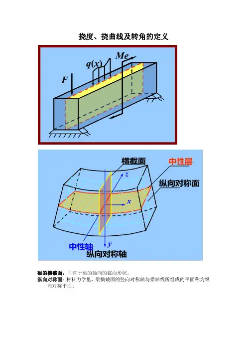
挠度、挠曲线及转角的定义
梁的横截面:垂直于梁的轴向的截面形状。
纵向对称面:材料力学里,梁横截面的竖向对称轴与梁轴线所组成的平面称为纵向对称平面。
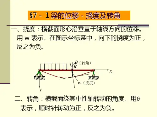
挠度:弯曲变形时横截面形心沿与轴线垂直方向的线位移称为挠度,用 y表示。
挠曲线:如图,平面弯曲时,梁的轴线将变为一条在梁的纵对称面内的平面曲线,该曲线称为梁的挠曲线。
转角:弯曲变形时横截面相对其原来的位置转过的角度称为转角,用θ表示。
挠曲线方程:挠度和转角的值都是随截面位置而变的。
在讨论弯曲变形问题时,通常选取坐标轴x向右为正,坐标轴y向上为正。
选定坐标轴之后,梁各横截面处的挠度y将是横截面位置坐标x的函数,其表达式称为梁的挠曲线方程,即
y = f ( x )
显然,挠曲线方程在截面x处的值,即等于该截面处的挠度。
根据微积分知识,挠曲线的斜率为
因工程实际中梁的转角θ之值十分微小,可近似认为
可见,挠曲线在截面位置坐标x处的斜率,或挠度y对坐标x的一阶导数,等于该截面的转角。
关于挠度和转角正负符号的规定:在如图选定的坐标系中,向上的挠度为正,逆时针转向的转角为正。
挠度仪就是据此原理所做,不过是通过转角在刻度尺上显示杆的软硬度。
综上所述:在一定长度内(X表示)我们所用的箭杆挠度(Y表示)越大,杆子越软。
越小杆子越硬。
在一定范围内适合轻重磅不同的弓所搭配的箭。
传统弓一般在箭的合适重量搭配的情况下,选硬(挠度Y值小)不选软(挠度Y值大)。
无人驾驶车辆_北京理工大学中国大学mooc课后章节答案期末考试题库2023年1.关于相机坐标系、图像物理坐标系、图像像素坐标系的单位,以下正确的是()答案:米,米,像素2.下列属于实时增量式路径规划算法的是()答案:AD*3.求图中,从P0到P6的最短路径长度( )答案:134.已知阿克曼转向车辆运动学公式为则下列描述正确的是( )答案:v是后轮速度,(x,y)是后轮中心位置,φ是车辆方位角。
5.电动助力转向系统的无人化改造方案有()答案:列出的三个方案都可以.6.下列说法正确的有()答案:像素坐标系与图像物理坐标系在同一个平面相机坐标系的坐标与图像物理坐标系的坐标都是连续的7.下面哪些属于传统的机器学习方法()答案:随机森林AdaBoost支持向量机逻辑回归8.关于激光雷达slam,以下描述正确的有()答案:Gmapping 采用粒子滤波的方法,在二维激光雷达slam中使用广泛。
Karto SLAM采用图优化的方法计算更新激光雷达的位姿。
Cartographer以子地图为单位构建全局地图,以消除构图过程中产生的累积误差。
Hector SLAM采用基于扫描匹配的方法,在传感器精度高的情况下,定位建图效果好。
9.视觉里程计的目的是根据拍摄的图像估计相机的运动,其关键步骤包括()答案:特征提取局部优化运动估计特征匹配10.通过卫星播发导航电文的方式可以将电离层时间误差、对流层时间误差、多路径延迟误差和卫星位置j等信息提供给用户。
答案:正确11.物体到透镜远大于透镜焦距时,可以把成像到透镜中心的水平距离当作焦距。
答案:正确12.用RRT方法进行路径搜索,只要环境相同,每次搜索结果就相同。
答案:错误13.相机与激光雷达数据融合主要是指空间数据融合。
()答案:错误14.Adaboost方法的自适应性表现在,根据一定规则自动调整样本的权值以及强分类器的权值。
()答案:错误15.小孔模型公式中负号表示成的像是倒立的。
imu 的加速度、角速度、角度关系嘿,朋友!咱们来聊聊 IMU 里那加速度、角速度和角度的奇妙关系,这可真是个有趣又有点烧脑的话题。
你想啊,加速度就像个急性子的短跑运动员,总是急冲冲地往前冲。
它能告诉我们物体在某个方向上速度变化的快慢。
比如说,当你猛地踩下汽车油门,那一瞬间感受到的那种推背感,就是加速度在起作用啦。
角速度呢,则像个爱转圈的舞者。
它专门描述物体绕着某个轴旋转的快慢。
就好比一个旋转木马,转得快还是慢,角速度说了算。
而角度呢,就像是个记录员,默默地把物体转过的路程都记下来。
这三者的关系,就好比一场精彩的舞蹈表演。
加速度是那激昂的音乐节奏,催促着舞者(物体)动起来;角速度则是舞者优美的旋转动作,时快时慢;角度就是这场舞蹈留下的轨迹,记录着每一个精彩的瞬间。
要是没有加速度,物体的运动就会变得平淡无奇,就像没了调料的饭菜,索然无味。
没有角速度,那物体就没法灵活地旋转,好比不会拐弯的汽车,多无趣呀!而没有角度,我们就没法知道物体到底转了多少,这就像迷失了方向的船只,不知道自己走了多远。
咱们生活里也有好多和这类似的例子。
比如骑自行车,你用力蹬的时候,那产生的就是加速度;车轮快速转动,这就是角速度;而车轮转过的圈数,对应的不就是角度嘛。
再想想游乐场里的摩天轮,它启动加速上升,这是加速度在使劲;缓缓转动的过程,就是角速度在发挥作用;最终它转到的位置,不就是角度的体现吗?所以说,IMU 里这加速度、角速度和角度的关系,那可是紧密相连,缺一不可。
它们共同为我们描绘出物体运动的精彩画卷,让我们能更清楚地了解这个充满活力的世界。
总之,搞清楚这三者的关系,能让我们在科技的海洋里畅游得更自在,也能让我们更好地去探索和理解这个神奇的世界。
你说是不是呢?。
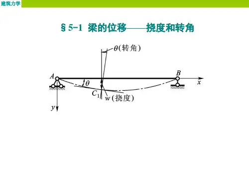
第5章梁弯曲时的位移(Displacement)§ 5-1梁的位移一挠度及转角〃(转角)w (挠度)挠度(Deflection):向下为正转角(Rotation):顺时针为正挠曲线方程:w=f(x)转角方程:0 u tan 3 = w r = f r{x) § 7-2梁的挠曲线近似微分方程及其积分纯弯曲时:因为在小变形情况下:EI P1 + w 2EI叽7El2.取心0___ ) MM>0M #/<0__ X\/^MMvO H ^>0挠曲线的近似微分方程:= -M (x )1 M1.将纯弯曲的公式一=一推广至横力弯曲 p EIAf>0 冶">0EIw = —J | J M (")d"]dx+ Cx+ DEIw =EIw n= -M (x)E/" = -jM (x)dx + C例:弯曲刚度为E/的悬臂梁如图,求梁的挠曲线方程 及其最大挠度Wmn% °解:X 截面处弯矩方程为: M(X )=-*O (/_X )2 梁的挠曲线方程:F/vv^=-M (x) =^(/-x)2EIw r = f^-(/-x)2dx = - —(/-x/ +CJ 2 6EZw = J|--^(/-x)3 + C]d¥ = ^-(/-x)4+Cr + £>曰“」=_¥(/“F+C 利用位移条件确定积分常数:边界条件:I ) x = 0 处w = 0念广+ £> = 024D = 一必24乘=券(1寸+3给2)兀=0处皿=0 -鱼■尸+c = o6当兀=/o£_6EIVV max八吉一敎T+瞥]例:求图示弯曲刚度为£7的简支梁的挠曲线和转角方程,并确定其最大挠度和最大转角。
Fl解:1)求弯矩方程4£)段:M)(x)= -y~x段:A/2(x) = — x - F(x-tz)2)梁的挠曲线方程 AD 段: DB 段: 3)积分 4D 段:段: EIw : = -M| (x) = -F — x EIw ; = —M .(x) = -F yF (兀一aEI W [=- — X 2+C,FhEAv. =- — x'+C.x + D. 16/ ' I, Fh 2 F (x-«)2EIw^ = ------ x + ---------- - + C 7- 2/ 2 - 中 Fb 3 F (x-a^ 厂 c El= ---------- x + ------------- 卜 C^x +- 6/ 6 Ph AD 段:E/vv ;=- —x 2+C fFb EI\v x = ------ x 3+ C.x + D x 1 6/ 1 1沏段:曰以"卫,〜 21 2 -Fb 3 F (x^af 厂 门 --—X -\ k C^X + D,4)确定积分常数位移边界条件:a ) x = 0时,VV, =0P =0EIw. = —+ C.x161 1段:EIw ;=- 2161位移连续条件:FhAD 段:EIw\= ------ 宀 C\21h^lw x = ----- x +1 6/ 1DB 段:曰以=—卫,+ G- 21 2 - 中 _ Fb 3 F (x-ctf EI = --------- x + -------------- + C Q X + D. 26/ 6 2 b)兀=/时,w 2 =0~ — l 3+ F Q _ a)3+C 2l+D^ =0 6/ 6FhAD 段:EIw\= ------ 宀 C\21 EIw } = -^-x y+ C.x16/ 1 Fb 2F (x_d)2厂JT + — -------- 乙 + G2 -------------- K C^x + D, a) x = d 时,w, = w 2Fb + C x ci = ---- a + C^ct + 61 ~ ~C x a = C 、a +D 2空刃刖一6/耐 _ -x 3+ C x x2F (x-a^—JT +------ +C°21 2 -中 _ Fb 3 F (x-a )3 厂 门 EI= ---------- X + ------------ + CryX + D. 26/ 6 2b )兀=幺时,VP 2*Fb 2 Fb 2 ----- a 十 C ] = ----- c i + C21 1 21 2 Q=c 2D } =0Fb^ F (l-a )3厂7 c n / +—^ + CJ + = 0 61 6 2 2 C {a = C 2a + D 】C.=c 2求得:G = G =穿孑一,)6/D {=D 2 =0maxFl2=±-----16E =w c =Fp_48£/AD段:^' = w,} = 2iEI ^2~b ^~X'6/E/ LV 7」沏段:&2 = W2 = -^— y(x-6/)~ +^(/2-h2)-21EI \_b3= Fb_£(X_R)3 + 02-6IEI b' 7 V 7当载荷连续条件:1.关于分段的确定原则:挠曲线微分方程发生了变化,均需分段。
Reference free method for real time monitoring of bridgedeflectionsKarim Helmi a ,Todd Taylor b ,Ali Zarafshan b ,Farhad Ansari b ,⇑a Construction and Building Engineering Department,Arab Academy for Science,Technology and Maritime Transport,Abu Qir,Alexandria,EgyptbCivil and Material Engineering Department,University of Illinois at Chicago,2095Engineering Research Facility,842W.Taylor Street,Chicago,IL 60607,USAa r t i c l e i n f o Article history:Received 9February 2014Revised 31August 2015Accepted 1September 2015Available online 15September 2015Keywords:Bridges Real time DeflectionFiber optic sensors Fiber Bragg gratings Tiltmeter TrucksStructural health monitoringa b s t r a c tMonitoring deflections provides a powerful diagnostic tool for structural health monitoring of bridges.Excessive deflections under service loads may be indicative of structural changes,damage and deteriora-tion.For the real time monitoring of deflections under operating traffic loads,it is often difficult to estab-lish a fixed reference point for displacement transducers either because the bridge crosses over a body of water or a roadway.Moreover,vandalism and environmental conditions disrupt and more than likely alter the fixity of the reference points.The work presented in this study pertains to the development of a method for real time remote monitoring of bridge deflections.From the practical point of view,the primary attribute of the proposed method is its capability for making reference free estimates of bridge deflections.The formulations employ the measured rotations and curvatures of the bridge for this purpose.The feasibility of the approach was tested on two different highway bridges.Both bridges were instrumented with a number of different fiber optic sensors that included tiltmeters and strain gauges.Conventional transducers and displacement measurement devices were also used in parallel in order to evaluate the performance of the proposed method.A series of load tests were conducted at both bridge sites that included use of trucks with known weights.In addition,finite element models were developed and employed for further verification of the proposed approach.Field test measurement results and their correlations with the conventional methods as well as comparison with the finite element models are described in this article.Ó2015Elsevier Ltd.All rights reserved.1.IntroductionBridges are designed to carry the intended design loads and per-form efficiently during their service lives.In-service performance is attributed to structural response in terms of deflections,cracking and inelastic deformations.In general,these performance charac-teristics pertain to serviceability.For example,American Associa-tion of State Highway and Transportation Officials (AASHTO)provides optional limitations on live load deflections as a fraction of the span length (e.g.span length/800).The deflection limitation controls at the design stage are mainly established to accommo-date motorists’comfort.Alternatively,monitoring of deflections provides a powerful diagnostic tool for structural health monitor-ing (SHM)of bridges.Gradual or sudden changes in-service load deflections are indicative of structural changes,damage or deteri-oration.For example crack growth in girders,corrosion of various reinforced concrete elements,support movements,inelastic deformations of steel girders,bearing failures,debonding of steel reinforcement and other phenomena all fall into this category.The measured deflection response can be used in a finite element model of the bridge to back calculate residual capacity,compare the in-service versus designed behavior,or to assess the extent of damage.Linear displacement transducers such as linear variable differ-ential transformers (LVDT)are employed for direct measurement of deflections.They are often used during load tests when the bridge is closed to traffic or when it is possible to use a fixed refer-ence point for the transducers [1,2].For real time monitoring of deflections under operating traffic loads it is often difficult to establish a fixed reference point for displacement transducers,either because the bridge crosses over a body of water or a road-way.Moreover,vandalism and environmental perturbations could dislocate or cause the movement of the reference points.Other methods that have proven to be effective for periodic measurements but not suitable for real time long term monitoring of bridges include laser Doppler vibrometery (LDV),use of total stations,photogrammetry,and microwave radar.Examples include Jauregi et al.’s [3]work on digital close-range terrestrial photogrammetry (DCRTP)in which their laboratory and field tests on steel and prestressed concrete girder bridges indicated close/10.1016/j.engstruct.2015.09.0020141-0296/Ó2015Elsevier Ltd.All rights reserved.⇑Corresponding author.Tel.:+13129963428.E-mail addresses:kareem.helmy@ (K.Helmi),ttaylo20@ (T.Taylor),ali.zarafshan@ (A.Zarafshan),fansari@ (F.Ansari).agreements with total station readings and elastic analysis.While this technique is applicable only to measurements under static loading conditions,more advanced3D studies,including long exposure imagery are being developed for dynamic measurements [4].LDVs have been employed in remote monitoring of transverse dynamic displacements in stay cables[5].Also,LDVs can be used while the bridge is subjected to traffic loads and the scanning ver-sion of LDV(SLDV)is capable of multi-point measurements[6]. Deflection measurements by LDVs however,depend on measuring the speed of vibrations,and they are ineffective when bridges vibrate at low frequencies,i.e.slow speeds during rush hours.In a manner similar to LDV,radar interferometry has been employed for periodic remote monitoring of bridge deflections.Gentile and Bernardini[7]demonstrated the applicability of the microwave based interferometric technique for static as well as dynamic measurements in laboratory experiments andfield applications in bridges.Global Positioning Systems(GPS)have been used for real time monitoring of displacements in a number of applications,including tall buildings[8],towers[9],and bridge decks and pylons[10–12]. The reported activities are promising since over the years the res-olution and error in the measured responses have improved from several centimeters to a few millimeters,and sampling frequencies of up to100Hz[12,13].The disadvantages of GPS systems include errors due to multipath and loss of lock.These errors occur because it is not always possible to maintain a robust geometric configura-tion of satellites in view at all times[10,14].Sanli et al.[15]proposed an indirect method to measure the bridge deflections by a combination of tiltmeters and LVDTs.A con-crete slab on steel girder bridge was employed for testing the method.They used electrolytic tiltmeters with capability for oper-ating under adverse thermal and high humidity environments on the bridge.Their method involved the use of a cubic spline function for computation of deflections from acquired data.Their results on the live load tests of the Drweca River Bridge compared well with the results from LVDT measurements.The drawback with their method was the fact that the computations required direct mea-surement of deflections from LVDTs at the locations of tiltmeters in order to establish reference.A number of methods have been developed based onfiber optic Bragg grating(FBG)sensors[16,17].The use of FBG sensors resulted in higher resolution and lower noise measurements due to the sensitivity and immunity of the optical sensors to electrical and electromagnetic interference.The results have been promising due to the fact that FBG measured strains provided better esti-mates of deflections than the measurements with conventional optic sensors were used for high resolution monitoring of rotations and strains.The elastic curve formulations were programmed into the interrogation units of the sensors at two bridge sites for auto-mated real time remote monitoring operations.The approach described herein does not require ground-reference or the use of displacement sensors for monitoring the deflections.The method is described next,followed by implementation at the bridge sites and comparison of the results with deflections measured by con-ventional methods and those obtained from thefinite element analysis of the bridge.2.Method2.1.Description and formulationFig.1corresponds to a simple beam subjected to an arbitrary load and its response in terms of rotations,u and deflection,d.Assuming that the rotation along the beam at any given point in time could be represented with an n th order polynomial,the rela-tionship can be expressed as:u¼a1x nþa2x nÀ1þÁÁÁþa i x nÀiþ1þÁÁÁþa n xþa nþ1ð1Þwhere u is the rotation,x is the distance along the beam and a i is the polynomial coefficient.The curvature of the beam at any point is calculated by:j¼M=EI¼e=yð2Þwhere j is the curvature,M is the bending moment,E is the mod-ulus of elasticity,I is the moment of inertia,e is the strain and y is the distance of the section from the neutral axis for which the strain is computed.The relation between the rotation and the curvature is given by the following relation[18]:j¼d u=dxð3ÞThe curvature,therefore is calculated by differentiating Eq.(1) with respect to x,resulting in the following relationship:j¼na1x nÀ1þðnÀ1Þa2x nÀ2þÁÁÁþðnÀiþ1Þa i x nÀiþÁÁÁþa nÀ1xþa nð4ÞThe relationship between the rotation and deflection is[18];d¼Zu dxð5Þwhere d is the deflection at any point along the beam.Deflection isFig.1.Schematic view of the deflected shape of a beam.K.Helmi et al./Engineering Structures103(2015)116–124117d¼a1ðnþ1Þxnþ1þa2nx nþÁÁÁþa inþ2Àix nþ2ÀiþÁÁÁþa n2x2þa nþ1xð7ÞDeflection at a given point in time is computed by using Eq.(7) provided that the polynomial coefficients are known.These coeffi-cients are obtained by solving a system of equations,where the curvatures,rotations,deflections or any combination thereof are known or measured at locations along the beam length.Curvatures are obtained from measured strains using Eq.(2).Rotations are either measured using tiltmeters,or known from support condi-tions,e.g.zero rotation atfixed ends.Provided that curvatures, rotations and deflections are known at n+1or more points,a sys-tem of equations can be constructed and solved for the polynomial coefficients as shown below:x n u1x nÀ1u1ÁÁÁx u11...............x n ui x nÀ1u iÁÁÁx u i1nx nÀ1j1ðnÀ1Þx nÀ2j1ÁÁÁ10...............nx nÀ1j j ðnÀ1Þx nÀ2jjÁÁÁ10x nþ1 d1x nd1ÁÁÁx2d1x d1...............x nþ1 d k x nd kx2d k2 6666 66 66 66 66 66 66 66 66 66 4377777777777777777777775a1a2......a na nþ1266666666664377777777775¼u1...u ij1...j jd1...d k266666666666666666664377777777777777777775ð8Þinstrumented withfiber optic FBG tiltmeters and strain gauges.Acubic spline curve was used to represent the deflected shape,requiring at least four points of data to derive its equation.Thebridge in California was instrumented with four tiltmeters andtherefore computation of deflections did not require any additionaldata to derive the equation for the deflected shape.The bridge inIllinois was instrumented with three tiltmeters and therefore,anadditional point of data was required to derive the equation ofthe deflected shape.The additional point was obtained by calculat-ing the curvature from the strain readings of a strain gauge locatedat the midspan using Eq.(2).Field implementation of the proposedmethodology and real time remote monitoring of deflections aredescribed in the following section of this article.3.Test program3.1.Description of the bridgesField tests involved instrumentation of two typical highwaybridges,a prestressed concrete box girder bridge in Elk Grove Cal-ifornia and a concrete slab on steel girder bridge in Elmhurst Illi-nois.The bridges are shown in Figs.2and3.The bridge in California is located30miles south of Sacramento.The bridge consists of two separate sections carrying the north andsouthbound traffic of Interstate5over Lambert Road in the city ofElk Grove.The southbound section of the bridge was instrumentedin this study.The superstructure of the bridge is comprised of acontinuous concrete box girder span with a reinforced concrete Fig.2.Two span concrete box girder bridge in California.Fig.3.Three span concrete deck on steel girder bridge in Illinois.118K.Helmi et al./Engineering Structures103(2015)116–124during the sensor installation activities and load tests in order evaluate the precision of the deflections based on the methodology introduced in this study.Elevation and section views of the I-5Bridge with the locations the four tiltmeters as well as point A where the deflections were measured by LDV are shown in Fig.9.Fig.10shows an elevationFig.4.Strain gauge mounted to lower flange of surface of steel girder.Fig.5.Tiltmeter mounted on the girder web inside the concrete box girder.Fig.6.Site Interrogation unit and processor within NEMA rated enclosure.Fig.7.LDV employed for measurement of California bridge deflections.view of the Salt Creek Bridge with the locations of the three tilt-meters and strain gauge used.3.3.Field test program3.3.1.Concrete box girder bridgeA dump truck with a trailer was employed for the tests.The truck and trailer had a combined weight of 36.08metric ton (79.5kips).Fig.11shows the axle configurations of the truck and the attached trailer.Axle weights are given in Table 1.To minimize the effects of traffic on the controlled tests,live load tests were per-formed at night.Moreover,traffic was stopped prior to the bridge for a period of seven to ten minutes during each truck load test.Live load tests consisted of ten passes at two different truck speeds and at distances away from the western edge of the bridge.Details of the load test runs are given in Table 2.A total of eight passes were conducted at very slow pseudo-static speed over the bridge.The two high speed tests were conducted at normalcomputed through integration.Therefore,the LDV was not suitable for use in monitoring the deflections for lower speed truck tests.Tiltmeters however were able to collect the data corresponding to the slow speed truck loadings.Since it was not possible to use the LDV for the evaluation of the tiltmeter data at slow speeds the finite element model was employed for the evaluation of the sensors’data.In the finite element model,the axle configuration of the truck that was used for the load tests was employed as the simulated moving load at the speed of about 8km/h (5mph).Under the moving load condition,rotations of points on the model corresponding to the exact locations of the installed tiltmeters were recorded.Test run numbers nine and ten were performed at highway speed of 89km/h (55mph).A sampling frequency of 500Hz was selected for both the LDV and the fiber optic sensors.Fig.8.LVDT installed on one of the girders at the Salt Creek Bridge.Fig.9.(a)Elevation view.(b)Cross-section view of I-5Bridge.Fig.10.Elevation view of the Salt Creek Bridge.Fig.11.Truck and trailer axle load configurations.Table 1Test truck axle weight.System Axle 1Axle 2Axle 3Axle 4Axle 5Metric (kg)81887666691773255987fps (lb)18,05016,90015,25016,15013,200Table 2Details of load test runs.3.3.2.Concrete slab on steel girder bridgeA number of live load tests were conducted on the Slab on gir-der bridge at Salt Creek.Tests involved a random selection of weighed trucks from the nearby weigh station and acquisition of data during their passage over the bridge.The Salt Creek Bridge crossed the river and made it difficult to use the LDV as an inde-pendent measure of deflections.Instead,an LVDT was installed at the center of the middle span for this purpose.Also,since there were fewer tiltmeters installed,a strain gauge at the mid span location was used for calculating curvature of the beam.Therefore, in addition to the rotations,the radius of curvature was also employed as a known parameter in the solution of Eqs.(7)and (8)for the computation of the deflections.A sampling frequency of50Hz was selected for data acquisition by thefiber optic sensors and the LVDT.In order to reduce the higher frequency noise com-ponents,data was processed with a low-pass Butterworthfilter of the deflections measured by the method presented in this study. The FE model of the I-5Bridge was developed using the commercial structural analysis program SAP2000[22].Four node shell ele-ments were used to represent the top and bottomflanges,the webs and diaphragms.Eight node solid elements were used to model the beam over the middle pier.Fig.12shows the FE model of the bridge. Material properties and geometry of the structure were modeled using the original design drawings of the bridge.Verification of the FE model was accomplished by comparing the measured tiltmeter rotations to the FE model calculated rotations during slow speed load tests numbers2and7which were conducted on the bridge.The test runs were chosen randomly as representatives of the two extreme load paths that were conducted during the test.The recorded tiltmeter and FEM rotations were in good agreement as demonstrated by the sample comparison curves shown in Figs.13and14.The average differ-Fig.12.FEM model of I-5Bridge.Fig.13.Measured rotations vs FEM calculated rotations for tiltmeter2(test run2).Fig.14.Measured rotations vs FEM calculated rotations for tiltmeter3(test run7).K.Helmi et al./Engineering Structures103(2015)116–124121parison of mid span deflection calculated from tiltmeter data andmodel at pseudo-static truck speed(run2).parison of mid span deflection calculated from tiltmeter data andmodel at pseudo-static truck speed(run4).parison of mid span deflection calculated from tiltmeter data andmodel at pseudo-static truck speed(run7).LDV uses the Doppler Shift of the laser which is only applicableapplications involving dynamics and sufficient change in frequencydue to displacements.Therefore,for the slower speed truck runs,evaluation of the proposed method was achieved by comparingFig.18.Deflection at point A calculated from tiltmeter data compared to LDV readings for runs#9and#10.slight phase shifts between the responses recorded by the two methods.One reason,for this behavior is an insufficient number of sensors for constructing higher order polynomials.The other reason is presence of dynamic effects due to the interaction between the bridge and the truck which is more pronounced in this bridge because of its larger stiffness in comparison to the box girder bridge at I-5.5.Summary and conclusionsThe work presented in this study pertained to the development of a method for real time remote monitoring of bridge deflections. The primary attribute of the proposed method is its capability for making reference free estimates of bridge deflections.The formula-tions employ the measured rotations and curvatures of the bridge for the computation of deflections.In general,installation of either four tiltmeters,or a combination of tiltmeters,strain gauges,and displacement sensors providing information about four points along the span length is sufficient when the deflection shape is rep-resented by cubic splines.The tiltmeters,and the strain gauges employed herein,where based on a common FBG sensing platform with the same precisions and employed the same interrogation unit.Depending on the number of sensors,a polynomial can be for-mulated to estimate the elastic shape of the bridge.Installation of more sensors results in the formulation of higher order polynomi-als and more precise definition of the elastic curve.Field tests involved evaluating the method at two different bridges;a pre-stressed concrete box girder bridge in California and a concrete slab on steel girder bridge in Illinois.The box girder bridge was instrumented with four tilt meters along one of the spans,and the slab on girder bridge was instrumented with three tiltmeters and a strain gauge.In general,field test deflections monitored by the method described herein were in reasonable agreement with the independent measurements acquired by the conventional approaches.However,some of the deflections corresponding to the higher speed truck tests did not correlate with the independent tests.Because of limited number of tests,it is not clear whether the errors associated with the higher speed truck tests for the box gir-der bridge were systematic or random.More research is necessary in order to further evaluate the method in terms of truck speeds, bridge stiffness and types.Moreover,future work needs to also study the minimum quantity and proper spatial distribution of sensors along the span lengths for accurate estimation of deflec-tions.It is further noted that the method presented herein was tested on two bridges with span lengths of14and39m in length. The applicability of the method to longer span bridges has not been verified,and therefore,the application is limited to short to med-ium span bridges.AcknowledgementThis research is based on work supported by the National Science Foundation(PIRE program)grant number0730259. References[1]Cavadas Filipe,Rodrigues Carlos,Felix Carlos,et al.Post-rehabilitationassessment of a centenary steel bridge through numerical and experimental analysis.J Constr Steel Res2013;80:264–77.[2]Ekholm K,Kliger R,Crocetti R.Full-scale ultimate-load test of a stress-laminated-timber bridge deck.J Bridge Eng2012;17(4):691–9.[3]Jauregui David V,White Kenneth R,Woodward Clinton B,et al.Noncontactphotogrammetric measurement of vertical bridge deflection.J Bridge Eng 2003;8(4):212–22./10.1061/(ASCE)1084-0702(2003)8:4 (212).[4]McCarthy DM,Chandler JH,Palmeri A.3D case studies of monitoring dynamicstructural tests using long exposure imagery.ISPRS:Int Arch Photogramm 2014;5:407–11.[5]Tabatabai H.In:Inspection and maintenance of bridge stay cable systems.NCHRP synthesis,vol.353.National Academies Press;2006.[6]Talebinejad I,Fischer C,Ansari F.Simplified technique for remote monitoringof deflection in arch structures.J Exp Tech2013;37(1):68–72.[7]Gentile Carmelo,Bernardini Giulia.An interferometric radar for non-contactmeasurement of deflections on civil engineering structures:laboratory and full-scale tests.Struct Infrastruct Eng2010;6(5):521–34.[8]Celebi M,Sanli A.GPS in pioneering dynamic monitoring of long-periodstructures.Earthq Spect2002;18(1):47–61.[9]Lovse JW,Teskey WF,Lachapelle G,Cannon ME.Dynamic deformationmonitoring of tall structure using GPS technology.J Surv Eng1995;121(1):35–40.[10]Roberts GW,Meng X,Dodson A.Integrating a global positioning system andaccelerometers to monitor the deflection of bridges.J Surv Eng2004;130(2):65–72.[11]Nakamura SI.GPS measurement of wind-induced suspension bridge girderdisplacements.J Struct Eng2000;126(12):1413–9.[12]Watson C,Watson T,Coleman R.Structural monitoring of cable-stayed bridge:analysis of GPS versus modeled deflections.J Surv Eng2007;133(1):23–8. [13]Moschas Fanis,Stiros Stathis.Noise characteristics of high-frequency,short-duration GPS records from analysis of identical,collocated instruments.Measurement2013;46(4):1488–506.[14]Yi Ting-Hua,Li Hong-Nan,Gu Ming.Characterization and extraction of globalpositioning system multipath signals using an improvedparticle-filtering parison of the measured deflection by the tiltmeters and the LVDT.algorithm.J Meas Sci Technol2011;22(7)./10.1088/0957-0233/22/7/075101.[15]Sanli AK et al.Testing bridges by using tiltmeter measurements.Transport ResRec2000;2(1696):111–7.[16]Kim NS,Cho NS.Estimating deflection of a simple beam model usingfiberoptic Bragg-grating sensors.Exp Mech2004;44(4):433–9./10.1177/0014485104045431.[17]Chang SJ,Kim NS.Estimation of displacement response from FBG Strainsensors using empirical mode decomposition technique.Exp Mech2012;52(6):573–89./10.1007/s11340-011-9522-z.[18]Gere James.Mechanics of materials.6th ed.Toronto:Cengage Learning;2006.[19]Ansari F.Practical implementation of opticalfiber sensors in civil structuralhealth monitoring.J Intell Mater Syst Struct2007;18(8):879–89.[20]Meng D,Ansari F.Dampedfiber optic low-frequency tiltmeter for real-timemonitoring of structural displacements.J Meas Sci Technol2013;24(12)./10.1088/0957-0233/24/12/125106.[21]Feng X,Sun CS,Zhang X,Ansari F.Determination of the coefficient of thermalexpansion with embedded long gauge opticalfiber sensor.J Meas Sci Technol 2010;21(6).[22]Computers and Structures Inc.,Structural analysis program,SAP2000version12(Computer Software).124K.Helmi et al./Engineering Structures103(2015)116–124。