
2-71
Microcontroller Instruction Set
For interrupt response time information, refer to the hardware description chapter.
Note:
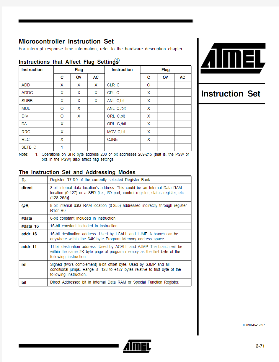
1.Operations on SFR byte address 208 or bit addresses 209-215 (that is, the PSW or
bits in the PSW) also affect flag settings.
Instructions that Affect Flag Settings (1)
Instruction
Flag Instruction
Flag C
OV AC C OV
AC
ADD X X X CLR C O ADDC
X X X CPL C X SUBB X X X
ANL C,bit X MUL O X ANL C,/bit X DIV O X
ORL C,bit X DA X ORL C,/bit X RRC X MOV C,bit X RLC X CJNE X
SETB C 1
The Instruction Set and Addressing Modes
R n Register R7-R0 of the currently selected Register Bank.
direct
8-bit internal data location’s address. This could be an Internal Data RAM location (0-127) or a SFR [i.e., I/O port, control register, status register, etc. (128-255)].
@R i 8-bit internal data RAM location (0-255) addressed indirectly through register R1or R0.
#data 8-bit constant included in instruction.#data 1616-bit constant included in instruction.
addr 1616-bit destination address. Used by LCALL and LJMP . A branch can be anywhere within the 64K byte Program Memory address space.
addr 11
11-bit destination address. Used by ACALL and AJMP . The branch will be within the same 2K byte page of program memory as the first byte of the following instruction.
rel
Signed (two’s complement) 8-bit offset byte. Used by SJMP and all
conditional jumps. Range is -128 to +127 bytes relative to first byte of the following instruction.
bit
Direct Addressed bit in Internal Data RAM or Special Function Register.
Instruction Set
2-72
Instruction Set Summary
Note:Key: [2B] = 2 Byte, [3B] = 3 Byte, [2C] = 2 Cycle, [4C] = 4 Cycle, Blank = 1 byte/1 cycle
12345670
NOP
JBC bit,rel [3B, 2C]JB bit, rel [3B, 2C]JNB bit, rel [3B, 2C]JC rel [2B, 2C]JNC rel [2B, 2C]JZ rel [2B, 2C]JNZ rel [2B, 2C]1
AJMP (P0)[2B, 2C]ACALL (P0)[2B, 2C]AJMP (P1)[2B, 2C]ACALL (P1)[2B, 2C]AJMP (P2)[2B, 2C]ACALL (P2)[2B, 2C]AJMP (P3)[2B, 2C]ACALL (P3)[2B, 2C]2
LJMP addr16[3B, 2C]LCALL addr16[3B, 2C]RET [2C]RETI [2C]ORL dir, A [2B]ANL dir, A [2B]XRL dir, a [2B]ORL C, bit [2B, 2C]3
RR A RRC A RL A RLC A ORL dir, #data [3B, 2C]ANL dir, #data [3B, 2C]XRL dir, #data [3B, 2C]JMP @A + DPTR
[2C]4
INC A DEC A ADD A, #data [2B]ADDC A, #data [2B]ORL A, #data [2B]ANL A, #data [2B]XRL A, #data [2B]MOV A, #data [2B]5
INC dir [2B]DEC dir [2B]ADD A, dir [2B]ADDC A, dir [2B]ORL A, dir [2B]ANL A, dir [2B]XRL A, dir [2B]MOV dir, #data [3B, 2C]6
INC @R0DEC @R0ADD A, @R0ADDC A, @R0ORL A, @R0ANL A, @R0XRL A, @R0MOV @R0, @data
[2B]7
INC @R1DEC @R1ADD A, @R1ADDC A, @R1ORL A, @R1ANL A, @R1XRL A, @R1MOV @R1, #data
[2B]8
INC R0DEC R0ADD A, R0ADDC A, R0ORL A, R0ANL A, R0XRL A, R0MOV R0, #data [2B]9
INC R1DEC R1ADD A, R1ADDC A, R1ORL A, R1ANL A, R1XRL A, R1MOV R1, #data [2B]A
INC R2DEC R2ADD A, R2ADDC A, R2ORL A, R2ANL A, R2XRL A, R2MOV R2, #data [2B]B
INC R3DEC R3ADD A, R3ADDC A, R3ORL A, R3ANL A, R3XRL A, R3MOV R3, #data [2B]C
INC R4DEC R4ADD A, R4ADDC A, R4ORL A, R4ANL A, R4XRL A, R4MOV R4, #data [2B]D
INC R5DEC R5ADD A, R5ADDC A, R5ORL A, R5ANL A, R5XRL A, R5MOV R5, #data [2B]E
INC R6DEC R6ADD A, R6ADDC A, R6ORL A, R6ANL A, R6XRL A, R6MOV R6, #data [2B]F
INC R7
DEC R7
ADD A, R7
ADDC A, R7
ORL A, R7
ANL A, R7
XRL A, R7
MOV R7, #data [2B]
Instruction Set
2-73
Instruction Set Summary (Continued)
Note:Key: [2B] = 2 Byte, [3B] = 3 Byte, [2C] = 2 Cycle, [4C] = 4 Cycle, Blank = 1 byte/1 cycle
8
9A B C D E F 0
SJMP REL [2B, 2C]MOV DPTR,#data 16[3B, 2C]ORL C, /bit [2B, 2C]ANL C, /bit [2B, 2C]PUSH dir [2B, 2C]POP dir [2B, 2C]MOVX A,@DPTR [2C]MOVX @DPTR, A
[2C]1
AJMP (P4)[2B, 2C]ACALL (P4)[2B, 2C]AJMP (P5)[2B, 2C]ACALL (P5)[2B, 2C]AJMP (P6)[2B, 2C]ACALL (P6)[2B, 2C]AJMP (P7)[2B, 2C]ACALL (P7)[2B, 2C]2
ANL C, bit [2B, 2C]MOV bit, C [2B, 2C]MOV C, bit [2B]CPL bit [2B]CLR bit [2B]SETB bit [2B]MOVX A, @R0[2C]MOVX wR0, A [2C]3
MOVC A,@A + PC [2C]MOVC A,@A + DPTR
[2C]INC DPTR [2C]CPL C CLR C SETB C MOVX A, @RI [2C]MOVX @RI, A [2C]4
DIV AB [2B, 4C]SUBB A, #data [2B]MUL AB [4C]
CJNE A,#data, rel [3B, 2C]SWAP A DA A CLR A CPL A 5
MOV dir, dir [3B, 2C]SUBB A, dir [2B]CJNE A, dir, rel [3B, 2C]XCH A, dir [2B]DJNZ dir, rel [3B, 2C]MOV A, dir [2B]MOV dir, A [2B]6
MOV dir, @R0[2B, 2C]SUBB A, @R0MOV @R0, dir [2B, 2C]CJNE
@R0, #data, rel
[3B, 2C]XCH A, @R0XCHD A, @R0MOV A, @R0MOV @R0, A 7
MOV dir, @R1[2B, 2C]SUBB A, @R1MOV @R1, dir [2B, 2C]CJNE
@R1, #data, rel
[3B, 2C]XCH A, @R1XCHD A, @R1MOV A, @R1MOV @R1, A 8
MOV dir, R0[2B, 2C]SUBB A, R0MOV R0, dir [2B, 2C]CJNE R0, #data, rel [3B, 2C]XCH A, R0DJNZ R0, rel [2B, 2C]MOV A, R0MOV R0, A 9
MOV dir, R1[2B, 2C]SUBB A, R1MOV R1, dir [2B, 2C]CJNE R1, #data, rel [3B, 2C]XCH A, R1DJNZ R1, rel [2B, 2C]MOV A, R1MOV R1, A A
MOV dir, R2[2B, 2C]SUBB A, R2MOV R2, dir [2B, 2C]CJNE R2, #data, rel [3B, 2C]XCH A, R2DJNZ R2, rel [2B, 2C]MOV A, R2MOV R2, A B
MOV dir, R3[2B, 2C]SUBB A, R3MOV R3, dir [2B, 2C]CJNE R3, #data, rel [3B, 2C]XCH A, R3DJNZ R3, rel [2B, 2C]MOV A, R3MOV R3, A C
MOV dir, R4[2B, 2C]SUBB A, R4MOV R4, dir [2B, 2C]CJNE R4, #data, rel [3B, 2C]XCH A, R4DJNZ R4, rel [2B, 2C]MOV A, R4MOV R4, A D
MOV dir, R5[2B, 2C]SUBB A, R5MOV R5, dir [2B, 2C]CJNE R5, #data, rel [3B, 2C]XCH A, R5DJNZ R5, rel [2B, 2C]MOV A, R5MOV R5, A E
MOV dir, R6[2B, 2C]SUBB A, R6MOV R6, dir [2B, 2C]CJNE R6, #data, rel [3B, 2C]XCH A, R6DJNZ R6, rel [2B, 2C]MOV A, R6MOV R6. A F
MOV dir, R7[2B, 2C]
SUBB A, R7
MOV R7, dir [2B, 2C]CJNE R7, #data, rel [3B, 2C]
XCH A, R7
DJNZ R7, rel [2B, 2C]
MOV A, R7
MOV R7, A
Instruction Set
2-74
Table 1. AT89 Instruction Set Summary (1)
Note: 1.All mnemonics copyrighted ? Intel Corp., 1980.
Mnemonic
Description
Byte
Oscillator Period
ARITHMETIC OPERATIONS ADD A,R n Add register to Accumulator 112ADD A,direct Add direct byte to Accumulator 212ADD A,@R i Add indirect RAM to Accumulator
112ADD A,#data Add immediate data to Accumulator
212ADDC A,R n Add register to
Accumulator with Carry 112ADDC A,direct Add direct byte to
Accumulator with Carry 212ADDC A,@R i Add indirect RAM to Accumulator with Carry 112ADDC A,#data Add immediate data to Acc with Carry 212SUBB A,R n Subtract Register from Acc with borrow
112SUBB A,direct Subtract direct byte from Acc with borrow 212SUBB A,@R i Subtract indirect RAM from ACC with borrow 112SUBB A,#data Subtract immediate data from Acc with borrow 212INC A Increment Accumulator 112INC R n Increment register 112INC direct Increment direct byte 212INC @R i Increment direct RAM 112DEC A Decrement Accumulator 112DEC R n Decrement Register 112DEC direct Decrement direct byte 212DEC @R i Decrement indirect RAM 112INC DPTR Increment Data Pointer 124MUL AB Multiply A & B 148DIV AB Divide A by B 148DA
A
Decimal Adjust Accumulator
1
12
Mnemonic
Description
Byte
Oscillator Period
LOGICAL OPERATIONS
ANL A,R n AND Register to Accumulator 112ANL A,direct AND direct byte to Accumulator 212ANL A,@R i AND indirect RAM to Accumulator
112ANL A,#data AND immediate data to Accumulator 212ANL direct,A AND Accumulator to direct byte
212ANL direct,#data AND immediate data to direct byte 324ORL A,R n OR register to Accumulator 112ORL A,direct OR direct byte to Accumulator 212ORL A,@R i OR indirect RAM to Accumulator
112ORL A,#data OR immediate data to Accumulator
212ORL direct,A OR Accumulator to direct byte
212ORL direct,#data OR immediate data to direct byte
324XRL
A,R n
Exclusive-OR register to Accumulator
112XRL A,direct Exclusive-OR direct byte to Accumulator 212XRL
A,@R i
Exclusive-OR indirect RAM to Accumulator 112XRL A,#data Exclusive-OR immediate data to Accumulator 212XRL
direct,A
Exclusive-OR
Accumulator to direct byte
2
12
XRL direct,#data Exclusive-OR immediate data to direct byte 324CLR A Clear Accumulator 112CPL A Complement Accumulator
112RL A Rotate Accumulator Left 112RLC
A
Rotate Accumulator Left through the Carry
1
12
LOGICAL OPERATIONS (continued)
Instruction Set
2-75
RR A Rotate Accumulator Right
112RRC A Rotate Accumulator Right through the Carry 112SWAP
A
Swap nibbles within the Accumulator
1
12
DATA TRANSFER MOV A,R n Move register to Accumulator 112
MOV A,direct Move direct byte to Accumulator
212
MOV A,@R i Move indirect RAM to Accumulator
112
MOV A,#data Move immediate data to Accumulator
212
MOV R n ,A Move Accumulator to register
112
MOV R n ,direct Move direct byte to register
224MOV R n ,#data Move immediate data to register
212MOV direct,A Move Accumulator to direct byte
212MOV direct,R n Move register to direct byte
224MOV direct,direct Move direct byte to direct 324MOV direct,@R i Move indirect RAM to direct byte
224MOV direct,#data Move immediate data to direct byte
324MOV @R i ,A Move Accumulator to indirect RAM 112MOV @R i ,direct Move direct byte to indirect RAM
224MOV @R i ,#data
Move immediate data to indirect RAM
212MOV
DPTR,#data16Load Data Pointer with a
16-bit constant
324MOVC A,@A+DPTR Move Code byte relative to DPTR to Acc
124MOVC A,@A+PC Move Code byte relative to PC to Acc
124MOVX
A,@R i
Move External RAM (8-bit addr) to Acc
1
24
DATA TRANSFER (continued)
Mnemonic Description Byte Oscillator Period
MOVX A,@DPTR Move Exernal RAM (16-bit addr) to Acc 124MOVX @R i ,A Move Acc to External RAM (8-bit addr) 124MOVX @DPTR,A Move Acc to External RAM (16-bit addr)124PUSH
direct
Push direct byte onto stack
224POP
direct Pop direct byte from stack
224XCH
A,R n Exchange register with Accumulator
112XCH
A,direct Exchange direct byte with Accumulator 212XCH
A,@R i Exchange indirect RAM with Accumulator 112XCHD
A,@R i Exchange low-order Digit indirect RAM with Acc
1
12
BOOLEAN VARIABLE MANIPULATION CLR C Clear Carry 112CLR bit Clear direct bit 212SETB C Set Carry 112SETB bit Set direct bit 212CPL C Complement Carry 112CPL bit Complement direct bit 212ANL C,bit AND direct bit to CARRY 224ANL C,/bit AND complement of direct bit to Carry 224ORL C,bit OR direct bit to Carry 224ORL C,/bit OR complement of direct bit to Carry
224MOV C,bit Move direct bit to Carry 212MOV bit,C Move Carry to direct bit 224JC rel Jump if Carry is set 224JNC rel Jump if Carry not set 224JB bit,rel Jump if direct Bit is set 324JNB bit,rel Jump if direct Bit is Not set
324JBC
bit,rel
Jump if direct Bit is set & clear bit
3
24
PROGRAM BRANCHING
Mnemonic Description
Byte Oscillator Period
Instruction Set
2-76
ACALL addr11Absolute Subroutine Call 224LCALL addr16Long Subroutine Call 324RET Return from Subroutine 124RETI Return from interrupt 124AJMP addr11Absolute Jump 224LJMP addr16Long Jump
324SJMP rel Short Jump (relative addr)
224JMP @A+DPTR Jump indirect relative to the DPTR
124JZ rel Jump if Accumulator is Zero
224JNZ rel Jump if Accumulator is Not Zero
224CJNE
A,direct,rel
Compare direct byte to Acc and Jump if Not Equal
3
24
CJNE A,#data,rel Compare immediate to Acc and Jump if Not Equal
324
CJNE
R n ,#data,rel
Compare immediate to register and Jump if Not Equal
324
CJNE
@R i ,#data,rel
Compare immediate to indirect and Jump if Not Equal
324
DJNZ R n ,rel Decrement register and Jump if Not Zero 224DJNZ direct,rel Decrement direct byte and Jump if Not Zero 324NOP
No Operation
1
12
Mnemonic Description
Byte Oscillator Period
Instruction Set
2-77
Table 2. Instruction Opcodes in Hexadecimal Order
Hex Code Number of Bytes
Mnemonic Operands
001NOP 012AJMP code addr 023LJMP code addr 031RR A 041INC A 052INC data addr 061INC @R0071INC @R1081INC R0091INC R10A 1INC R20B 1INC R30C 1INC R40D 1INC R50E 1INC R60F 1INC R7
103JBC bit addr,code addr 112ACALL code addr 123LCALL code addr 131RRC A 141DEC A 152DEC data addr 161DEC @R0171DEC @R1181DEC R0191DEC R11A 1DEC R21B 1DEC R31C 1DEC R41D 1DEC R51E 1DEC R61F 1DEC R7
203JB bit addr,code addr 212AJMP code addr 221RET 231RL A 242ADD A,#data 25
2
ADD
A,data addr Hex Code Number of Bytes
Mnemonic Operands 261ADD A,@R0271ADD A,@R1281ADD A,R0291ADD A,R12A 1ADD A,R22B 1ADD A,R32C 1ADD A,R42D 1ADD A,R52E 1ADD A,R62F 1ADD A,R7
303JNB bit addr,code addr 312ACALL code addr
321RETI 331RLC A 342ADDC A,#data 352ADDC A,data addr 361ADDC A,@R0371ADDC A,@R1381ADDC A,R0391ADDC A,R13A 1ADDC A,R23B 1ADDC A,R33C 1ADDC A,R43D 1ADDC A,R53E 1ADDC A,R63F 1ADDC A,R7402JC code addr 412AJMP code addr 422ORL data addr,A 433ORL data addr,#data 442ORL A,#data 452ORL A,data addr 461ORL A,@R0471ORL A,@R1481ORL A,R0491ORL A,R14A
1
ORL
A,R2
Instruction Set
2-78
4B 1ORL A,R34C 1ORL A,R44D 1ORL A,R54E 1ORL A,R64F 1ORL A,R7502JNC code addr 512ACALL code addr 522ANL data addr,A 533ANL data addr,#data 542ANL A,#data 552ANL A,data addr 561ANL A,@R0571ANL A,@R1581ANL A,R0591ANL A,R15A 1ANL A,R25B 1ANL A,R35C 1ANL A,R45D 1ANL A,R55E 1ANL A,R65F 1ANL A,R7602JZ code addr 612AJMP code addr 622XRL data addr,A 633XRL data addr,#data 642XRL A,#data 652XRL A,data addr 661XRL A,@R0671XRL A,@R1681XRL A,R0691XRL A,R16A 1XRL A,R26B 1XRL A,R36C 1XRL A,R46D 1XRL A,R56E 1XRL A,R66F 1XRL A,R770
2
JNZ
code addr
Hex Code Number of Bytes
Mnemonic Operands 712ACALL code addr 722ORL C,bit addr 731JMP @A+DPTR 742MOV A,#data 753MOV data addr,#data 762MOV @R0,#data 772MOV @R1,#data 782MOV R0,#data 792MOV R1,#data 7A 2MOV R2,#data 7B 2MOV R3,#data 7C 2MOV R4,#data 7D 2MOV R5,#data 7E 2MOV R6,#data 7F 2MOV R7,#data 802SJMP code addr 812AJMP code addr 822ANL C,bit addr 831MOVC A,@A+PC 841DIV AB
853MOV data addr,data addr 862MOV data addr,@R0872MOV data addr,@R1882MOV data addr,R0892MOV data addr,R18A 2MOV data addr,R28B 2MOV data addr,R38C 2MOV data addr,R48D 2MOV data addr,R58E 2MOV data addr,R68F 2MOV data addr,R7903MOV DPTR,#data 912ACALL code addr 922MOV bit addr,C 931MOVC A,@A+DPTR 942SUBB A,#data 952SUBB A,data addr 96
1
SUBB
A,@R0
Hex Code Number of Bytes
Mnemonic Operands
Instruction Set
2-79
971SUBB A,@R1981SUBB A,R0991SUBB A,R19A 1SUBB A,R29B 1SUBB A,R39C 1SUBB A,R49D 1SUBB A,R59E 1SUBB A,R69F 1SUBB A,R7A02ORL C,/bit addr A12AJMP code addr A22MOV C,bit addr A31INC DPTR A41
MUL AB
A5reserved A62MOV @R0,data addr A72MOV @R1,data addr A82MOV R0,data addr A92MOV R1,data addr AA 2MOV R2,data addr AB 2MOV R3,data addr AC 2MOV R4,data addr AD 2MOV R5,data addr AE 2MOV R6,data addr AF 2MOV R7,data addr B02ANL C,/bit addr B12ACALL code addr B22CPL bit addr B31CPL C
B43CJNE A,#data,code addr B53CJNE A,data addr,code addr B63CJNE @R0,#data,code addr B73CJNE @R1,#data,code addr B83CJNE R0,#data,code addr B93CJNE R1,#data,code addr BA 3CJNE R2,#data,code addr BB 3CJNE R3,#data,code addr BC
3CJNE
R4,#data,code addr Hex Code Number of Bytes
Mnemonic Operands BD 3CJNE R5,#data,code addr BE 3CJNE R6,#data,code addr BF 3CJNE R7,#data,code addr C02PUSH data addr C12AJMP code addr C22CLR bit addr C31CLR C C41SWAP A
C52XCH A,data addr C61XCH A,@R0C71XCH A,@R1C81XCH A,R0C91XCH A,R1CA 1XCH A,R2CB 1XCH A,R3CC 1XCH A,R4CD 1XCH A,R5CE 1XCH A,R6CF 1XCH A,R7D02POP data addr D12ACALL code addr D22SETB bit addr D31SETB C D41DA A
D53DJNZ data addr,code addr D61XCHD A,@R0D71XCHD A,@R1D82DJNZ R0,code addr D92DJNZ R1,code addr DA 2DJNZ R2,code addr DB 2DJNZ R3,code addr DC 2DJNZ R4,code addr DD 2DJNZ R5,code addr DE 2DJNZ R6,code addr DF 2DJNZ R7,code addr E01MOVX A,@DPTR E12AJMP code addr E2
1
MOVX
A,@R0
Hex Code Number of Bytes
Mnemonic Operands
Instruction Set
2-80
E31MOVX A,@R1E41CLR A
E52MOV A,data addr E61MOV A,@R0E71MOV A,@R1E81MOV A,R0E91MOV A,R1EA 1MOV A,R2EB 1MOV A,R3EC 1MOV A,R4ED 1MOV A,R5EE 1MOV A,R6EF 1MOV A,R7F01MOVX @DPTR,A F12ACALL code addr F21MOVX @R0,A F31MOVX @R1,A F41CPL A
F52MOV data addr,A F61MOV @R0,A F71MOV @R1,A F81MOV R0,A F91MOV R1,A FA 1MOV R2,A FB 1MOV R3,A FC 1MOV R4,A FD 1MOV R5,A FE 1MOV R6,A FF
1
MOV
R7,A
Hex Code Number of Bytes
Mnemonic Operands
Instruction Set
2-81
Instruction Definitions
ACALL addr11
Function:Absolute Call
Description:ACALL unconditionally calls a subroutine located at the indicated address. The instruction increments the PC
twice to obtain the address of the following instruction, then pushes the 16-bit result onto the stack (low-order byte first) and increments the Stack Pointer twice. The destination address is obtained by successively
concatenating the five high-order bits of the incremented PC, opcode bits 7 through 5, and the second byte of the instruction. The subroutine called must therefore start within the same 2 K block of the program memory as the first byte of the instruction following ACALL. No flags are affected.Example:Initially SP equals 07H. The label SUBRTN is at program memory location 0345 H. After executing the following
instruction,
ACALL SUBRTN
at location 0123H, SP contains 09H, internal RAM locations 08H and 09H will contain 25H and 01H, respectively , and the PC contains 0345H.
Bytes:2Cycles:2Encoding:a10
a9
a8
1
1
a7
a6
a5
a4
a3
a2
a1
a0
Operation:ACALL
(PC) ← (PC) + 2(SP) ← (SP) + 1((SP)) ← (PC 7-0)(SP) ← (SP) + 1((SP)) ← (PC 15-8)
(PC 10-0) ← page address
Instruction Set
2-82
ADD A,
Function:Add
Description:ADD adds the byte variable indicated to the Accumulator, leaving the result in the Accumulator. The carry and
auxiliary-carry flags are set, respectively, if there is a carry-out from bit 7 or bit 3, and cleared otherwise. When
adding unsigned integers, the carry flag indicates an overflow occurred.
OV is set if there is a carry-out of bit 6 but not out of bit 7, or a carry-out of bit 7 but not bit 6; otherwise, OV is cleared. When adding signed integers, OV indicates a negative number produced as the sum of two positive operands, or a positive sum from two negative operands.
Four source operand addressing modes are allowed: register, direct, register-indirect, or immediate.
Example:The Accumulator holds 0C3H (1100001lB), and register 0 holds 0AAH (10101010B). The following instruction,
ADD A,R0leaves 6DH (01101101B) in the Accumulator with the AC flag cleared and both the carry flag and OV set to 1.
ADD A,R n
Bytes:1Cycles:1Encoding:
1
1
r
r
r
Operation:ADD
(A) ← (A) + (R n )
ADD A,direct
Bytes:2Cycles:1Encoding:
1
1
1
direct
address
Operation:ADD
(A)
← (A) + (direct)
ADD A,@R i
Bytes:1Cycles:1Encoding:
1
1
1
i
Operation:ADD
(A) ← (A) + ((R i ))
ADD A,#data
Bytes:2Cycles:1Encoding:
1
1
immediate data
Operation:ADD
(A)
← (A) + #data
Instruction Set
2-83
ADDC A,
Function:Add with Carry
Description:ADDC simultaneously adds the byte variable indicated, the carry flag and the Accumulator contents, leaving the result in the Accumulator. The carry and auxiliary-carry flags are set respectively, if there is a carry-out from bit 7 or bit 3, and cleared otherwise. When adding unsigned integers, the carry flag indicates an overflow occurred.
OV is set if there is a carry-out of bit 6 but not out of bit 7, or a carry-out of bit 7 but not out of bit 6; otherwise OV is cleared. When adding signed integers, OV indicates a negative number produced as the sum of two positive operands or a positive sum from two negative operands.
Four source operand addressing modes are allowed: register, direct, register-indirect, or immediate.
Example:The Accumulator holds 0C3H (11000011B) and register 0 holds 0AAH (10101010B) with the carry flag set. The
following instruction,ADDC A,R0
leaves 6EH (01101110B) in the Accumulator with AC cleared and both the Carry flag and OV set to 1.
ADDC A,R n
Bytes:1Cycles:1Encoding:
1
1
1
r
r
r
Operation:ADDC
(A) ← (A) + (C) + (R n )
ADDC A,direct
Bytes:2Cycles:1Encoding:
1
1
1
1
direct
address
Operation:ADDC
(A)
← (A) + (C) + (direct)
ADDC A,@R i
Bytes:1Cycles:1Encoding:
1
1
1
1
i
Operation:ADDC
(A) ← (A) + (C) + ((R i ))
ADDC A,#data
Bytes:2Cycles:1Encoding:
1
1
1
immediate
data
Operation:ADDC
(A) ← (A) + (C) + #data
Instruction Set
2-84
AJMP addr11
ANL
Function:Absolute Jump
Description:AJMP transfers program execution to the indicated address, which is formed at run-time by concatenating the
high-order five bits of the PC (after incrementing the PC twice), opcode bits 7 through 5, and the second byte of the instruction. The destination must therfore be within the same 2 K block of program memory as the first byte of the instruction following AJMP .Example:The label JMP ADR is at program memory location 0123H. The following instruction,
AJMP JMP ADR
is at location 0345H and loads the PC with 0123H.
Bytes:2Cycles:2Encoding:a10
a9
a8
1
a7
a6
a5
a4
a3
a2
a1
a0
Operation:AJMP
(PC) ← (PC) + 2
(PC 10-0) ← page address
Function:Logical-AND for byte variables
Description:ANL performs the bitwise logical-AND operation between the variables indicated and stores the results in the
destination variable. No flags are affected.
The two operands allow six addressing mode combinations. When the destination is the Accumulator, the source can use register, direct, register-indirect, or immediate addressing; when the destination is a direct address, the source can be the Accumulator or immediate data.
Note: When this instruction is used to modify an output port, the value used as the original port data will be read from the output data latch, not the input pins.
Example:If the Accumulator holds 0C3H (1100001lB), and register 0 holds 55H (01010101B), then the following
instruction,
ANL A,R0
leaves 41H (01000001B) in the Accumulator.
When the destination is a directly addressed byte, this instruction clears combinations of bits in any RAM location or hardware register. The mask byte determining the pattern of bits to be cleared would either be a constant contained in the instruction or a value computed in the Accumulator at run-time. The following instruction,
ANL P1,#01110011B
clears bits 7, 3, and 2 of output port 1.
ANL A,R n
Bytes:1Cycles:1Encoding:
1
1
1
r
r
r
Operation:ANL
(A) ← (A) ∧
(R n )
Instruction Set
2-85
ANL A,direct
Bytes:2Cycles:1Encoding:
1
1
1
1
direct address
Operation:ANL
(A) ← (A) ∧
(direct)
ANL A,@R i
Bytes:1Cycles:1Encoding:
1
1
1
1
i
Operation:ANL
(A) ← (A) ∧
((R i ))ANL A,#data
Bytes:2Cycles:1Encoding:
1
1
1
immediate data
Operation:ANL
(A)
← (A) ∧
#data
ANL direct,A
Bytes:2Cycles:1Encoding:
1
1
1
direct
address
Operation:ANL
(direct) ← (direct)
∧ (A)
ANL direct,#data
Bytes:3Cycles:2Encoding:
1
1
1
1
direct address
immediate data
Operation:ANL
(direct) ← (direct)
∧ #data
Instruction Set
2-86
ANL C,
Function:Logical-AND for bit variables
Description:If the Boolean value of the source bit is a logical 0, then ANL C clears the carry flag; otherwise, this instruction
leaves the carry flag in its current state. A slash ( / ) preceding the operand in the assembly language indicates that the logical complement of the addressed bit is used as the source value, but the source bit itself is not affected . No other flags are affected.
Only direct addressing is allowed for the source operand.
Example:Set the carry flag if, and only if, P1.0 = 1, ACC.7 = 1, and OV = 0:
MOV C,P1.0;LOAD CARRY WITH INPUT PIN ST A TE ANL C,ACC.7;AND CARRY WITH ACCUM. BIT 7
ANL C,/OV
;AND WITH INVERSE OF OVERFLOW FLAG
ANL C,bit
Bytes:2Cycles:2
Encoding:
1000
1
bit
address Operation:ANL
(C)
← (C) ∧
(bit)ANL C,/bit
Bytes:2Cycles:2Encoding:
1
1
1
bit
address
Operation:ANL
(C)
← (C) ∧
(bit)
Instruction Set
2-87
CJNE
Function:Compare and Jump if Not Equal.
Description:CJNE compares the magnitudes of the first two operands and branches if their values are not equal. The branch
destination is computed by adding the signed relative-displacement in the last instruction byte to the PC, after incrementing the PC to the start of the next instruction. The carry flag is set if the unsigned integer value of
The first two operands allow four addressing mode combinations: the Accumulator may be compared with any directly addressed byte or immediate data, and any indirect RAM location or working register can be compared with an immediate constant.
Example:The Accumulator contains 34H. Register 7 contains 56H. The first instruction in the sequence,CJNE R7, # 60H, NOT_EQ
;
. . . . . . . . ;R7 = 60H.NOT_EQ: JC REQ_LOW ;IF R7 < 60H.;
. . .
. . . . .
;R7 > 60H.
sets the carry flag and branches to the instruction at label NOT_EQ. By testing the carry flag, this instruction
determines whether R7 is greater or less than 60H.
If the data being presented to Port 1 is also 34H, then the following instruction,WAIT:
CJNE
A, P1,WAIT
clears the carry flag and continues with the next instruction in sequence, since the Accumulator does equal the data read from P1. (If some other value was being input on P1, the program loops at this point until the P1 data changes to 34H.)
CJNE A,direct,rel
Bytes:3Cycles:2Encoding:
1
1
1
1
1
direct address
rel.
address
Operation:(PC)
← (PC) + 3
IF (A) < > (direct )THEN
(PC) ← (PC) + relative offset IF (A) < (direct )THEN
(C) ← 1ELSE
(C) ← 0
Instruction Set
2-88
CJNE A,#data,rel
Bytes:3Cycles:2Encoding:
1
1
1
1
immediate data
rel.
address
Operation:(PC) ← (PC) + 3
IF (A) < > data THEN
(PC) ← (PC) + relative offset IF (A) < data THEN
(C) ← 1ELSE
(C) ← 0
CJNE R n ,#data,rel
Bytes:3Cycles:2Encoding:
1
1
1
1
r
r
r
immediate data
rel. address
Operation:(PC) ← (PC) + 3
IF (R n ) < > data THEN
(PC) ← (PC) + relative offset IF (R n ) < data THEN
(C) ← 1ELSE
(C) ← 0
CJNE @R i ,data,rel
Bytes:3Cycles:2Encoding:
1
1
1
1
1
i
immediate data
rel.
address
Operation:(PC) ← (PC) + 3
IF ((R i )) < > data THEN
(PC) ← (PC) + relative offset IF ((R i )) < data THEN
(C) ← 1ELSE
(C) ← 0
Instruction Set
2-89
CLR A
CLR bit
Function:Clear Accumulator
Description:CLR A clears the Accumulator (all bits set to 0). No flags are affected
Example:The Accumulator contains 5CH (01011100B). The following instruction,CLR Aleaves the Accumulator set to 00H
(00000000B).Bytes:1Cycles:1
Encoding:11100100
Operation:CLR
(A) ← 0
Function:Clear bit
Description:CLR bit clears the indicated bit (reset to 0). No other flags are affected. CLR can operate on the carry flag or any
directly addressable bit.Example:Port 1 has previously been written with 5DH (01011101B). The following instruction,CLR P1.2 leaves the port set
to 59H (01011001B).
CLR C
Bytes:1Cycles:1Encoding:
1
1
1
1
Operation:CLR
(C) ← 0
CLR bit
Bytes:2Cycles:1Encoding:
1
1
1
bit
address
Operation:CLR
(bit)
← 0
Instruction Set
2-90
CPL A
CPL bit
Function:Complement Accumulator
Description:CPLA logically complements each bit of the Accumulator (one’s complement). Bits which previously contained a
1 are changed to a 0 and vice-versa. No flags are affected.Example:The Accumulator contains 5CH (01011100B). The following instruction,
CPL A
leaves the Accumulator set to 0A3H (10100011B).
Bytes:1Cycles:1Encoding:
1
1
1
1
1
Operation:CPL
(A) ← (A)
Function:Complement bit
Description:CPL bit complements the bit variable specified. A bit that had been a 1 is changed to 0 and vice-versa. No other
flags are affected. CLR can operate on the carry or any directly addressable bit.
Note: When this instruction is used to modify an output pin, the value used as the original data is read from the output data latch, not the input pin.
Example:Port 1 has previously been written with 5BH (01011101B). The following instruction sequence,CPL P1.1CPL
P1.2 leaves the port set to 5BH (01011011B).
CPL C
Bytes:1Cycles:1Encoding:
1
1
1
1
1
Operation:CPL
(C) ← (C)
CPL bit
Bytes:2Cycles:1Encoding:
1
1
1
1
bit
address
Operation:CPL
(bit)
← (bit)
51单片机汇编指令集 一、数据传送类指令(7种助记符) MOV(英文为Move):对内部数据寄存器RAM和特殊功能寄存器SFR的数据进行传送; MOVC(Move Code)读取程序存储器数据表格的数据传送; MOVX (Move External RAM) 对外部RAM的数据传送; XCH (Exchange) 字节交换; XCHD (Exchange low-order Digit) 低半字节交换; PUSH (Push onto Stack) 入栈; POP (Pop from Stack) 出栈; 二、算术运算类指令(8种助记符) ADD(Addition) 加法; ADDC(Add with Carry) 带进位加法; SUBB(Subtract with Borrow) 带借位减法; DA(Decimal Adjust) 十进制调整; INC(Increment) 加1; DEC(Decrement) 减1; MUL(Multiplication、Multiply) 乘法; DIV(Division、Divide) 除法; 三、逻辑运算类指令(10种助记符) ANL(AND Logic) 逻辑与; ORL(OR Logic) 逻辑或; XRL(Exclusive-OR Logic) 逻辑异或; CLR(Clear) 清零; CPL(Complement) 取反; RL(Rotate left) 循环左移; RLC(Rotate Left throught the Carry flag) 带进位循环左移; RR(Rotate Right) 循环右移; RRC (Rotate Right throught the Carry flag) 带进位循环右移; SWAP (Swap) 低4位与高4位交换; 四、控制转移类指令(17种助记符) ACALL(Absolute subroutine Call)子程序绝对调用; LCALL(Long subroutine Call)子程序长调用; RET(Return from subroutine)子程序返回; RETI(Return from Interruption)中断返回; SJMP(Short Jump)短转移; AJMP(Absolute Jump)绝对转移; LJMP(Long Jump)长转移; CJNE (Compare Jump if Not Equal)比较不相等则转移;
16位二进制数转换成BCD码的的快速算法-51单片机2010-02-18 00:43在做而论道上篇博文中,回答了一个16位二进制数转换成BCD码的问题,给出了一个网上广泛流传的经典转换程序。 程序可见: http: 32.html中的HEX2BCD子程序。 .说它经典,不仅是因为它已经流传已久,重要的是它的编程思路十分清晰,十分易于延伸推广。做而论道曾经利用它的思路,很容易的编写出了48位二进制数变换成16位BCD码的程序。 但是这个程序有个明显的缺点,就是执行时间太长,转换16位二进制数,就必须循环16遍,转换48位二进制数,就必须循环48遍。 上述的HEX2BCD子程序,虽然长度仅仅为26字节,执行时间却要用331个机器周期。.单片机系统多半是用于各种类型的控制场合,很多时候都是需要“争分夺秒”的,在低功耗系统设计中,也必须考虑因为运算时间长而增加系统耗电量的问题。 为了提高整机运行的速度,在多年前,做而论道就另外编写了一个转换程序,程序的长度为81字节,执行时间是81个机器周期,(这两个数字怎么这么巧!)执行时间仅仅是经典程序的!.近来,在网上发现了一个链接: ,也对这个经典转换程序进行了改进,话是说了不少,只是没有实质性的东西。这篇文章提到的程序,一直也没有找到,也难辩真假。 这篇文章好像是选自某个著名杂志,但是在术语的使用上,有着明显的漏洞,不像是专业人员的手笔。比如说文中提到的:
“使用51条指令代码,但执行这段程序却要耗费312个指令周期”,就是败笔。51条指令代码,真不知道说的是什么,指令周期是因各种机型和指令而异的,也不能表示确切的时间。 .下面说说做而论道的编程思路。;----------------------------------------------------------------------- ;已知16位二进制整数n以b15~b0表示,取值范围为0~65535。 ;那么可以写成: ; n = [b15 ~ b0] ;把16位数分解成高8位、低8位来写,也是常见的形式: ; n = [b15~b8] * 256 + [b7~b0] ;那么,写成下列形式,也就可以理解了: ; n = [b15~b12] * 4096 + [b11~b0] ;式中高4位[b15~b12]取值范围为0~15,代表了4096的个数; ;上式可以变形为: ; n = [b15~b12] * 4000 + {[b15~b12] * (100 - 4) + [b11~b0]} ;用x代表[b15~b12],有: ; n =x * 4000 + {x * (100 - 4) + [b11~b0]} ;即: ; n =4*x (千位) + x (百位) + [b11~b0] - 4*x ;写到这里,就可以看出一点BCD码变换的意思来了。 ;;上式中后面的位:
51单片机汇编指令速查表 指令格式功能简述字节数周期 一、数据传送类指令 MOV A, Rn 寄存器送累加器 1 1 MOV Rn,A 累加器送寄存器 1 1 MOV A ,@Ri 内部RAM单元送累加器 1 1 MOV @Ri ,A 累加器送内部RAM单元 1 1 MOV A ,#data 立即数送累加器 2 1 MOV A ,direct 直接寻址单元送累加器 2 1 MOV direct ,A 累加器送直接寻址单元 2 1 MOV Rn,#data 立即数送寄存器 2 1 MOV direct ,#data 立即数送直接寻址单元 3 2 MOV @Ri ,#data 立即数送内部RAM单元 2 1 MOV direct ,Rn 寄存器送直接寻址单元 2 2 MOV Rn ,direct 直接寻址单元送寄存器 2 2 MOV direct ,@Ri 内部RAM单元送直接寻址单元 2 2 MOV @Ri ,direct 直接寻址单元送内部RAM单元 2 2 MOV direct2,direct1 直接寻址单元送直接寻址单元 3 2 MOV DPTR ,#data16 16位立即数送数据指针 3 2 MOVX A ,@Ri 外部RAM单元送累加器(8位地址) 1 2 MOVX @Ri ,A 累加器送外部RAM单元(8位地址) 1 2 MOVX A ,@DPTR 外部RAM单元送累加器(16位地址) 1 2 MOVX @DPTR ,A 累加器送外部RAM单元(16位地址) 1 2 MOVC A ,@A+DPTR 查表数据送累加器(DPTR为基址) 1 2 MOVC A ,@A+PC 查表数据送累加器(PC为基址) 1 2 XCH A ,Rn 累加器与寄存器交换 1 1 XCH A ,@Ri 累加器与内部RAM单元交换 1 1 XCHD A ,direct 累加器与直接寻址单元交换 2 1 XCHD A ,@Ri 累加器与内部RAM单元低4位交换 1 1 SWAP A 累加器高4位与低4位交换 1 1 POP direct 栈顶弹出指令直接寻址单元 2 2 PUSH direct 直接寻址单元压入栈顶 2 2 二、算术运算类指令 ADD A, Rn 累加器加寄存器 1 1
单片机汇编指令一览表 作者:乡下人 助记符指令说明字节数周期数 (数据传递类指令) MOV A,Rn 寄存器传送到累加器 1 1 MOV A,direct 直接地址传送到累加器 2 1 MOV A,@Ri 累加器传送到外部RAM(8 地址) 1 1 MOV A,#data 立即数传送到累加器 2 1 MOV Rn,A 累加器传送到寄存器 1 1 MOV Rn,direct 直接地址传送到寄存器 2 2 MOV Rn,#data 累加器传送到直接地址 2 1 MOV direct,Rn 寄存器传送到直接地址 2 1 MOV direct,direct 直接地址传送到直接地址 3 2 MOV direct,A 累加器传送到直接地址 2 1 MOV direct,@Ri 间接RAM 传送到直接地址 2 2 MOV direct,#data 立即数传送到直接地址 3 2 MOV @Ri,A 直接地址传送到直接地址 1 2 MOV @Ri,direct 直接地址传送到间接RAM 2 1 MOV @Ri,#data 立即数传送到间接RAM 2 2 MOV DPTR,#data16 16 位常数加载到数据指针 3 1 MOVC A,@A+DPTR 代码字节传送到累加器 1 2 MOVC A,@A+PC 代码字节传送到累加器 1 2 MOVX A,@Ri 外部RAM(8 地址)传送到累加器 1 2 MOVX A,@DPTR 外部RAM(16 地址)传送到累加器 1 2 MOVX @Ri,A 累加器传送到外部RAM(8 地址) 1 2 MOVX @DPTR,A 累加器传送到外部RAM(16 地址) 1 2 PUSH direct 直接地址压入堆栈 2 2 POP direct 直接地址弹出堆栈 2 2 XCH A,Rn 寄存器和累加器交换 1 1 XCH A, direct 直接地址和累加器交换 2 1 XCH A, @Ri 间接RAM 和累加器交换 1 1 XCHD A, @Ri 间接RAM 和累加器交换低4 位字节 1 1 (算术运算类指令) INC A 累加器加1 1 1 INC Rn 寄存器加1 1 1 INC direct 直接地址加1 2 1 INC @Ri 间接RAM 加1 1 1 INC DPTR 数据指针加1 1 2 DEC A 累加器减1 1 1 DEC Rn 寄存器减1 1 1 DEC direct 直接地址减1 2 2
PIC 单片机端口电平变化中断使用必须注意的问题 PICC18使用说明 PIC 单片机常用伪指令 PIC单片机2009-02-19 11:16:40 阅读8 评论0 字号:大中小订阅 3.2.3 MPASM 的伪指令 我们在第一章中已经详细介绍了中档PIC 单片机的35 条指令,源程序的编写主要就是用这些基本的指令实现你的控制任务。但为了增加源程序的可读性和可维护性,我们引入了伪指令的概念。伪指令本身不会产生可执行的汇编指令,但它们可以帮组“管理”你编写的程序,其实用性和必要性绝不亚于35 条正真的汇编指令。我们在此着重介绍最常用的几种 伪指令。 #include 或include #include 伪指令的作用是把另外一个文件的内容全部包含复制到本伪指令所在的位置。 被包含复制的文件可以是任何形式的文本文件,当然文件中的内容和语法结构必须是MPASM 能够识别的。最经常被“include”的是针对PIC 单片机内部特殊功能寄存器定义的包含头文件,在MPLAB 安装后它们全部放在路径“ C:\Program Files\MPLAB IDE\MCHIP_Tools”下,每一个型号的PIC 单片机都有一个对应的预定义包含头文件,扩展名是“.inc”。除了一些符号预定义文件,你也可以把现有的其它程序文件作为一个代码模块直接“包含”进来作为自己程序的一部分。见例3-01。 #include
指令中常用符号说明 Rn当前寄存器区的8个工作寄存器R0~R7(n=0~7) Ri当前寄存器区可作为地址寄存器的2个工作寄存器R0和R1(i=0,1) Direct8位内部数据寄存器单元的地址及特殊功能寄存器的地址 #data表示8位常数(立即数) #data16表示16位常数 Add16表示16位地址 Addr11表示11位地址 Rel8位代符号的地址偏移量 Bit表示位地址 @间接寻址寄存器或基址寄存器的前缀 ( )表示括号中单元的内容 (( ))表示间接寻址的内容 指令系统 数据传送指令(8个助记符) 助记符中英文注释 MOV Move 移动 MOV A , Rn;Rn→A,寄存器Rn的内容送到累加器A MOV A , Direct;(direct)→A,直接地址的内容送A MOV A ,@ Ri;(Ri)→A,RI间址的内容送A MOV A , #data;data→A,立即数送A MOV Rn , A;A→Rn,累加器A的内容送寄存器Rn MOV Rn ,direct;(direct)→Rn,直接地址中的内容送Rn MOV Rn , #data;data→Rn,立即数送Rn MOV direct , A;A→(direct),累加器A中的内容送直接地址中 MOV direct , Rn;(Rn)→direct,寄存器的内容送到直接地址 MOV direct , direct;(direct)→direct,直接地址的内容送到直接地址 MOV direct , @Ri;((Ri))→direct,间址的内容送到直接地址 MOV direct , #data;8位立即数送到直接地址中 MOV @Ri , A;(A)→@Ri,累加器的内容送到间址中 MOV @Ri , direct;direct→@Ri,直接地址中的内容送到间址中 MOV @Ri , #data; data→@Ri ,8位立即数送到间址中 MOV DPTR , #data16;data16→DPTR,16位常数送入数据指针寄存器,高8位送入DPH,低8位送入DPL中(单片机中唯一一条16位数据传送指令) (MOV类指令共16条)
51 单片机汇编指令集 一、数据传送类指令( 7 种助记符) MOV(英文为Move :对内部数据寄存器RAM 和特殊功能寄存器SFR 的数据进行 传送; MOV Q Move Code )读取程序存储器数据表格的数据传送; MOVX (Move External RAM) 对外部 RAM 勺数据传送; XCH (Exchange) 字节交换; XCHD (Exchange low-order Digit) 低半字节交换; PUSH (Push onto Stack) 入栈; POP (Pop from Stack) 出栈; 二、算术运算类指令( 8 种助记符) ADD(Addition) 加法; ADDC(Add with Carry) 带进位加法; SUBB(Subtract with Borrow) 带借位减法; DA(Decimal Adjust) 十进制调整; INC(Increment) 加 1; DEC(Decrement) 减 1; MUL(Multiplication 、Multiply) 乘法; DIV(Division 、Divide) 除法; 三、逻辑运算类指令( 10 种助记符) ANL(AND Logic) 逻辑与; ORL(OR Logic) 逻辑或; XRL(Exclusive-OR Logic) 逻辑异或; CLR(Clear) 清零; CPL(Complement) 取反; RL(Rotate left) 循环左移; RLC(Rotate Left throught the Carry flag) RR(Rotate Right) 循环右移; RRC (Rotate Right throught the Carry flag) SWAP (Swap) 低 4 位与高 4 位交换; 四、控制转移类指令( 17 种助记符) ACALL ( Absolute subroutine Call )子程序绝对调用; LCALL ( Long subroutine Call )子程序长调用; RET ( Return from subroutine )子程序返回; RETI ( Return from Interruption )中断返回; SJMP ( Short Jump )短转移; AJMP ( Absolute Jump )绝对转移; LJMP( Long Jump )长转移; CJNE (Compare Jump if Not Equal) 比较不相等则转移; DJNZ (Decreme nt Jump if Not Zero) 减1后不为0则转移; JZ (Jump if Zero) 结果为0则转移; JNZ (Jump if Not Zero) 结果不为0则转移; JC (Jump if the Carry flag is set) 有进位则转移; JNC (Jump if Not Carry) 无进位则转移; JB (Jump if the Bit is set) 位为1则转移; JNB (Jump if the Bit is Not set) 位为0则转移; 带进位循环左移; 带进位循环右移;
PIC8位单片机汇编语言常用指令的识读(上) 各大类单片机的指令系统是没有通用性的,它是由单片机生产厂家规定的,所以用户必须遵循厂家规定的标准,才能达到应用单片机的目的。 PIC 8位单片机共有三个级别,有相对应的指令集。基本级PIC系列芯片共有指令33条,每条指令是12位字长;中级PIC系列芯片共有指令35条,每条指令是14位字长;高级PIC 系列芯片共有指令58条,每条指令是16位字长。其指令向下兼容。 在这里笔者介绍PIC 8位单片机汇编语言指令的组成及指令中符号的功能,以供初学者阅读相关书籍和资料时快速入门。 一、PIC汇编语言指令格式 PIC系列微控制器汇编语言指令与MCS-51系列单片机汇编语言一样,每条汇编语言指令由4个部分组成,其书写格式如下: 标号操作码助记符操作数1,操作数2;注释 指令格式说明如下:指令的4个部分之间由空格作隔离符,空格可以是1格或多格,以保证交叉汇编时,PC机能识别指令。 1 标号与MCS-51系列单片机功能相同,标号代表指令的符号地址。在程序汇编时,已赋以指令存储器地址的具体数值。汇编语言中采用符号地址(即标号)是便于查看、修改,尤其是便于指令转移地址的表示。标号是指令格式中的可选项,只有在被其它语句引用时才需派上标号。在无标号的情况下,指令助记符前面必须保留一个或一个以上的空格再写指令助记符。指令助记符不能占用标号的位置,否则该助记符会被汇编程序作标号误处理。 书写标号时,规定第一字符必须是字母或半角下划线“—”,它后面可以跟英文和数字字符、冒号(:)制符表等,并可任意组合。再有标号不能用操作码助记符和寄存器的代号表示。标号也可以单独占一行。 2 操作码助记符该字段是指令的必选项。该项可以是指令助记符,也可以由伪指令及宏命令组成,其作用是在交叉汇编时,“指令操作码助记符”与“操作码表”进行逐一比较,找出其相应的机器码一一代之。 3 操作数由操作数的数据值或以符号表示的数据或地址值组成。若操作数有两个,则两个操作数之间用逗号(,)分开。当操作数是常数时,常数可以是二进制、八进制、十进制或十六进制数。还可以是被定义过的标号、字符串和ASCⅡ码等。具体表示时,规定在二进制数前冠以字母“B”,例如B10011100;八进制数前冠以字母“O”,例如O257;十进制数前冠以字母“D”,例如D122;十六进制数前冠以“H”,例如H2F。在这里PIC 8位单片机默认进制是十六进制,在十六进制数之前加上Ox,如H2F可以写成Ox2F。 指令的操作数项也是可选项。 PIC系列与MCS-51系列8位单片机一样,存在寻址方法,即操作数的来源或去向问题。因PIC系列微控制器采用了精简指令集(RISC)结构体系,其寻址方式和指令都既少而又简单。其寻址方式根据操作数来源的不同,可分为立即数寻址、直接寻址、寄存器间接寻址和位寻址四种。所以PIC系列单片机指令中的操作数常常出现有关寄存器符号。有关的寻址实例,均可在本文的后面找到。 4 注释用来对程序作些说明,便于人们阅读程序。注释开始之前用分号(;)与其它部分相隔。当汇编程序检测到分号时,其后面的字符不再处理。值得注意:在用到子程序时应说明程序的入口条件、出口条件以及该程序应完成的功能和作用。 二、清零指令(共4条) 1 寄存器清零指令 实例:CLRW;寄存器W被清零 说明:该条指令很简单,其中W为PIC单片机的工作寄存器,相当于MCS-51系列单片机中的累加器A,CLR是英语Clear的缩写字母。 2 看门狗定时器清零指令。 实例:CLRWDT;看门狗定时器清零(若已赋值,同时清预分频器)
引言 软件设计更多地是一种工程,而不是一种个人艺术。如果不统一编程规范,最终写出的程序,其可读性将较差,这不仅给代码的理解带来障碍,增加维护阶段的工作量,同时不规范的代码隐含错误的可能性也比较大。 分析表明,编码阶段产生的错误当中,语法错误大概占20%左右,而由于未严格检查软件逻辑导致的错误、函数(模块)之间接口错误及由于代码可理解度低导致优化维护阶段对代码的错误修改引起的错误则占了一半以上。 可见,提高软件质量必须降低编码阶段的错误率。如何有效降低编码阶段的错误呢?这需要制定详细的软件编程规范,并培训每一位程序员,最终的结果可以把编码阶段的错误降至10%左右,同时也降低了程序的测试费用,效果相当显著。 本文从代码的可维护性(可读性、可理解性、可修改性)、代码逻辑与效率、函数(模块)接口、可测试性四个方面阐述了软件编程规范,规范分成规则和建议两种,其中规则部分为强制执行项目,而建议部分则不作强制,可根据习惯取舍。 1.排版 规则1 程序块使用缩进方式,函数和标号使用空格缩进,程序段混合使用TAB和空格缩进。缩进的目的是使程序结构清晰,便于阅读和理解。 默认宽度应为8个空格,由于Word中为4个空格,为示范清晰,此处用2个代替(下同)。例如: MOV R1, #00H MOV R2, #00H MOV PMR, #PMRNORMAL MOV DPS, #FLAGDPTR MOV DPTR, #ADDREEPROM read1kloop: read1kpage: INC R1 MOVX A, @DPTR MOV SBUF, A JNB TI, $ CLR TI INC DPTR CJNE R1, #20H, read1kpage INC R2 MOV R1, #00H CPL WDI CJNE R2, #20H, read1kloop ;END OF EEPROM 规则2
常用单片机汇编指令: 1 .MOV A,Rn寄存器内容送入累加器 2 .MOV A,direct 直接地址单元中的数据送入累加器 3 .MOV A,@Ri (i=0,1) 间接RAM中的数据送入累加器 4 .MOV A,#data 立即数送入累加器 5 .MOV Rn,A累加器内容送入寄存器 6 .MOV Rn,direct 直接地址单元中的数据送入寄存器 7 .MOV Rn,#data 立即数送入寄存器 8 .MOV direct,A 累加器内容送入直接地址单元 9 .MOV direct,Rn 寄存器内容送入直接地址单元 10. MOV direct,direct 直接地址单元中的数据送入另一个 直接地址单元 11 .MOV direct,@Ri (i=0,1) 间接RAM中的数据送入直接地址单元 12 MOV direct,#data 立即数送入直接地址单元 13 .MOV @Ri,A (i=0,1) 累加器内容送间接RAM单元 14 .MOV@Ri,direct (i=0,1)直接地址单元数据送入间接RAM 单元 15 .MOV @Ri,#data (i=0,1) 立即数送入间接RAM单元 16 .MOV DPTR,#data16 16 位立即数送入地址寄存器 17 .MOVC A,@A+DPTR以DPTR^基地址变址寻址单元中的数 据送入累加器
18 .MOVC A,@A+PC以PC为基地址变址寻址单元中的数据送入累加器 19 .MOVX A,@Ri (i=0,1) 外部RAM(8位地址)送入累加器 20 .MOVX A,@DPTR外部RAM(16位地址)送入累加器 21 .MOVX @Ri,A (i=0,1) 累计器送外部RAM(8位地址) 22 .MOVX @DPTR,A累计器送外部RAM( 16位地址) 23 .PUSH direct 直接地址单元中的数据压入堆栈 24 .POP direct 弹栈送直接地址单元 25 .XCH A,Rn 寄存器与累加器交换 26 .XCH A,direct 直接地址单元与累加器交换 27 .XCH A,@Ri (i=0,1) 间接RAM与累加器交换 28 .XCHD A,@Ri (i=0,1) 间接RAM的低半字节与累加器交换算术操作类指令: 1. ADD A,Rn 寄存器内容加到累加器 2 .ADD A,direct 直接地址单元的内容加到累加器 3 A.DD A,@Ri (i=0,1) 间接ROM的内容加到累加器 4 .ADD A,#data 立即数加到累加器 5 .ADDC A,Rn寄存器内容带进位加到累加器 6 .ADDC A,direct 直接地址单元的内容带进位加到累加器 7 .ADDC A,@Ri(i=0,1) 间接ROM的内容带进位加到累加器 8 .ADDC A,#data 立即数带进位加到累加器
1)数据传送类指令(7种助记符) MOV(英文为Move):对内部数据寄存器RAM和特殊功能寄存器SFR的数据进行传送; MOVC(Move Code)读取程序存储器数据表格的数据传送; MOVX (Move External RAM) 对外部RAM的数据传送; XCH (Exchange) 字节交换; XCHD (Exchange low-order Digit) 低半字节交换; PUSH (Push onto Stack) 入栈; POP (Pop from Stack) 出栈; (2)算术运算类指令(8种助记符) ADD(Addition) 加法; ADDC(Add with Carry) 带进位加法; SUBB(Subtract with Borrow) 带借位减法; DA(Decimal Adjust) 十进制调整; INC(Increment) 加1; DEC(Decrement) 减1; MUL(Multiplication、Multiply) 乘法; DIV(Division、Divide) 除法; (3)逻辑运算类指令(10种助记符) ANL(AND Logic) 逻辑与; ORL(OR Logic) 逻辑或; XRL(Exclusive-OR Logic) 逻辑异或; CLR(Clear) 清零; CPL(Complement) 取反; RL(Rotate left) 循环左移; RLC(Rotate Left throught the Carry flag) 带进位循环左移; RR(Rotate Right) 循环右移; RRC (Rotate Right throught the Carry flag) 带进位循环右移; SWAP (Swap) 低4位与高4位交换; (4)控制转移类指令(17种助记符) ACALL(Absolute subroutine Call)子程序绝对调用; LCALL(Long subroutine Call)子程序长调用; RET(Return from subroutine)子程序返回; RETI(Return from Interruption)中断返回; SJMP(Short Jump)短转移; AJMP(Absolute Jump)绝对转移; LJMP(Long Jump)长转移; CJNE (Compare Jump if Not Equal)比较不相等则转移; DJNZ (Decrement Jump if Not Zero)减1后不为0则转移; JZ (Jump if Zero)结果为0则转移; JNZ (Jump if Not Zero) 结果不为0则转移;
Rn: 表示当前寄存器区的8个工作寄存器R0~R7 Ri: 表示当前寄存器区的R0或R1,可作地址指针即间址寄存器(i=0或1) @: 为间接寄存器或基址寄存器的前缀. Direct: 表示8位内部数据存储单元的地址.它可以是内部RAM的单元地址0~127.特殊功能 寄存器SFR的地址(128~255)或名称, A: 累加器ACC. B: .特殊功能寄存器B,用于MUL和DIV指令中. C: 进位位Cy. #data: 表示包含在指令中的单字节(8位)立即数.如果用16位进制表示,后缀字母为”H”,数据范围00~0FFH,不得一字母开头;如果用16进制表示无须任何后缀,但必须在0~255之间. #data16: 表示包含在指令中的双字节(16位)立即数. Adda16: 表示16位的目的地址.用于LCALL和LJMP指令中,目的地址范围是从0000H~FFFFH的整个64KB存储地址空间. Adda11: 表示11位的目的地址.用于ACALL和AJMP的指令中,目的地址必须和下一条指令第一个字节同处一页. Rel: 表示8位带符号的相对偏移量.用语SJMP和所有的条件转移指令中.偏移量相对于下一条指令的第一个字节计算,在-128~+127范围内取值. DPTR: 为数据指针,可用作16位的地址寄存器. /: 加在位操作的前面,表示对该位进行非运算. bit: 表示内部可寻址位或特殊功能寄存器中的直接寻址位. “(x):寄存器或地址单元中的内容. ((x)): 有x见解寻址的单元中的内容. <-: 表示将箭头右边的内容传送至箭头的左边. $: 当前指令的地址.
单片机指令系统 (一) 内部数据传送指令 (1) 以累加器A为目的的传送指令: MOV A, #data ;(A)<-data MOV A, direct ;(A)<-(direct) MOV A, Rn ;(A)<-(Rn) MOV A, @Ri ;(A)<- ((Ri)) (2) 以通用寄存器Rn为目的的传送指令: MOV Rn, A ;(Rn)<-(A) MOV Rn, direct ; (Rn)<(direct)- MOV Rn, #data: ; (Rn)<-(data) (3) 以直接地址为目的的传送指令: MOV direct, A ;(direct)<-(A) MOV direct, Rn ; (direct)<-(Rn) MOV direct, direct2 ; (direct)<-(direct2) MOV direct, @Ri ; (direct)<-((Rn)) MOV direct, #data ; (direct)<-data (4) 以寄存器间接地址为目的的传送指令: MOV @Ri, A ;((Ri))<-(A) MOV @Ri, direct ;((Ri))<-(direct) MOV @Ri, #data ;((Ri))<-data (二) 数据指针赋值指令(16位数据传送指令) MOV DPTR, #data16; (三) 片外数据传送指令
单片机汇编指令 单片机汇编指令:为解决某些特定的问题代码中必须嵌入汇编语言以代替C语言完成的单片机的编程,汇编语言对于程序调试是不可或缺的。它包括:数据传送类指令,算术运算类指令,逻辑运算与循环类指令,控制转移类指令,位操作(布尔操作)类指令。 现在单片机的编程大多是C语言完成但有时代码中必须嵌入汇编语言解决某些特定的问题,对于程序调试汇编语言更是不可或缺 一.数据传送类指令: (1)一般传送指令: ①8位传送: 1 MOV A,Rn ;A←(Rn):寄存器内容送入累加器 2 MOV A,direct ;A←(direct):直接地址单元中的数据送入累加器 3 MOV A,@Ri ;A←((Ri)):间接RAM 中的数据送入累加器 4 MOV A,#data ;A←(data):立即数送入累加器 5 MOV Rn,A ;Rn←(A):累加器内容送入寄存器 6 MOV Rn,direct ;Rn←(direct):直接地址单元中的数据送入寄存器 7 MOV Rn,#data ;Rn←(data):立即数送入寄存器 8 MOV direct,A ;direct←(A):累加器内容送入直接地址单元 9 MOV direct,Rn ;direct←(Rn):寄存器内容送入直接地址单元 10 MOV direct,direct;direct←(direct):直接地址单元中的数据送入另一个直接地址单元 11 MOV direct,@Ri ;direct←(@Ri):间接RAM 中的数据送入直接地址单元 12 MOV direct,#data ;direct←(data):立即数送入直接地址单元 13 MOV @Ri,A;Ri←(A):累加器内容送入间接RAM 单元 14 MOV @Ri,direct ;Ri←(direct)直接地址单元数据送入间接RAM 单元 15 MOV @RI,#data ;Ri←(data):立即数送入间接RAM 单元 ②16位传送: 16 MOV DRTR,#data16 ;(DRTR) ←(data16):16 位立即数送入地址寄存器 (2)特殊传送指令: ⑤ ①读取常数表: 17 MOVC A,@A+DPTR ;A←((A)+(DPTR)):以DPTR为基地址变址寻址单元中的数据送入累加器 18 MOVC A,@A+PC;A←((A)+(PC)):以PC 为基地址变址寻址单元中的数据送入累加器 ②读写片外RAM及接口单元数据: 读片外RAM: 19 MOVX A,@Ri ;A←((Ri)):外部RAM(8 位地址)送入累加器 20 MOVX A,@DPTR ;A←((DPTR)):外部RAM(16 位地址)送入累加器
51汇编语言指令集 符号定义表 符号含义 Rn R0~R7寄存器n=0~7 Direct 直接地址,内部数据区的地址RAM(00H~7FH) SFR(80H~FFH) B,ACC,PSW,IP,P3, IE,P2,SCON,P1,TCON,P0 @Ri 间接地址Ri=R0或R1 8051/31RAM地址(00H~7FH) 8052/32RAM地址(00H~FFH) #data 8位常数 #data16 16位常数 Addr16 16位的目标地址 Addr11 11位的目标地址 Rel 相关地址 bit 内部数据RAM(20H~2FH),特殊功能寄存器的直接地址的位 指令介绍 指令字 节周 期 动作说明 算数运算指令 1.ADD A,Rn 1 1 将累加器与寄存器的内容相加,结果 存回累加器 2.ADD A,direct 2 1 将累加器与直接地址的内容相加,结 果存回累加器 3.ADD A,@Ri 1 1 将累加器与间接地址的内容相加,结 果存回累加器 4.ADD A,#data 2 1 将累加器与常数相加,结果存回累加 器 5.ADDC A,Rn 1 1 将累加器与寄存器的内容及进位C相 加,结果存回累加器 6.ADDC A,direct 2 1 将累加器与直接地址的内容及进位C 相加,结果存回累加器 7.ADDC A,@Ri 1 1 将累加器与间接地址的内容及进位C 相加,结果存回累加器 8.ADDC A,#data 2 1 将累加器与常数及进位C相加,结果 存回累加器 9.SUBB A,Rn 1 1 将累加器的值减去寄存器的值减借 位C,结果存回累加器 10.SUBB A,direct 2 1 将累加器的值减直接地址的值减借 位C,结果存回累加器 11.SUBB A,@Ri 1 1 将累加器的值减间接地址的值减借 位C,结果存回累加器 12.SUBB A,0data 2 1 将累加器的值减常数值减借位C,结 果存回累加器 13.INC A 1 1 将累加器的值加1 14.INC Rn 1 1 将寄存器的值加l 15.INC direct 2 1 将直接地址的内容加1 16.INC @Ri 1 1 将间接地址的内容加1 17.INC DPTR 1 1 数据指针寄存器值加1 说明:将16位的DPTR加1,当DPTR的低字节(DPL)从FFH溢出至00H时,会使高字节(DPH)加1,不影响任何标志位 18.DEC A 1 1 将累加器的值减1 19.DEC Rn 1 1 将寄存器的值减1 20.DEC direct 2 1 将直接地址的内容减1 21.DEC @Ri 1 1 将间接地址的内容减1 22.MUL AB 1 4 将累加器的值与B寄存器的值相 乘,乘积的低位字节存回累加器, 高位字节存回B寄存器 说明:将累加器A和寄存器B内的无符号整数相乘,产生16位的积,低位字节存入A,高位字节存入B寄存器。如果积大于FFH,则溢出标志位(OV)被设定为1,而进位标志位为0 23.DIV AB 1 4 将累加器的值除以B寄存器的值,结果 的商存回累加器,余数存回B寄存器 说明:无符号的除法运算,将累加器A除以B寄存器的值,商存入A,余数存入B。执行本指令后,进位位(C)及溢出位(OV)被清除为0 24.DA A 1 1 将累加器A作十进制调整, 若(A) 3-0>9或(AC)=1,则(A) 3-0←(A)3-0+6 若(A) 7-4>9或(C)=1,则(A) 7-4←(A)7-4+6 逻辑运算指令 ANL A,Rn 1 1 将累加器的值与寄存器的值做AND的逻 辑判断,结果存回累加器 ANL A,direct 2 1 将累加器的值与直接地址的内容做AND 的逻辑判断,结果存回累加器 ANL A,@Ri 1 1 将累加器的值与间接地址的内容做AND 的逻辑判断,结果存回累加器 ANL A,#data 2 1 将累加器的值与常数做AND的逻辑判 断,结果存回累加器 ANL direct,A 2 1 将直接地址的内容与累加器的值做AND 的逻辑判断,结果存回该直接地址 ANL direct,#data 3 2 将直接地址的内容与常数值做AND 的逻辑判断,结果存回该直接地址ORL A,Rn 1 1 将累加器的值与寄存器的值做OR的逻 辑判断,结果存回累加器 32.ORL A,direct 2 1 将累加器的值与直接地址的内容做OR 的逻辑判断,结果存回累加器33.ORL 1 1 将累加器的值与间接地址的内容做OR
51汇编指令大全 Rn: 表示当前寄存器区的8个工作寄存器R0~R7 Ri: 表示当前寄存器区的R0或R1,可作地址指针即间址寄存器(i=0或1) @: 为间接寄存器或基址寄存器的前缀. Direct: 表示8位内部数据存储单元的地址.它可以是内部RAM的单元地址0~127.特殊功能 寄存器SFR的地址(128~255)或名称, A: 累加器ACC. B: .特殊功能寄存器B,用于MUL和DIV指令中. C: 进位位Cy. #data: 表示包含在指令中的单字节(8位)立即数.如果用16位进制表示,后缀字母为”H”,数据范围00~0FFH,不得一字母开头;如果用16进制表示无须任何后缀,但必须在0~255之间. #data16: 表示包含在指令中的双字节(16位)立即数. Adda16: 表示16位的目的地址.用于LCALL和LJMP指令中,目的地址范围是从0000H~FFFFH的整个64KB存储地址空间. Adda11: 表示11位的目的地址.用于ACALL和AJMP的指令中,目的地址必须和下一条指令第一个字节同处一页. Rel: 表示8位带符号的相对偏移量.用语SJMP和所有的条件转移指令中.偏移量相对于下一条指令的第一个字节计算,在-128~+127范围内取值. DPTR: 为数据指针,可用作16位的地址寄存器. /: 加在位操作的前面,表示对该位进行非运算. bit: 表示内部可寻址位或特殊功能寄存器中的直接寻址位. “(x): 寄存器或地址单元中的内容. ((x)): 有x见解寻址的单元中的内容. <-: 表示将箭头右边的内容传送至箭头的左边. $: 当前指令的地址. 单片机指令系统 (一) 内部数据传送指令 (1) 以累加器A为目的的传送指令: MOV A, #data ;(A)<-data MOV A, direct ;(A)<-(direct) MOV A, Rn ;(A)<-(Rn) MOV A, @Ri ;(A)<- ((Ri)) (2) 以通用寄存器Rn为目的的传送指令: MOV Rn, A ;(Rn)<-(A) MOV Rn, direct ; (Rn)<(direct)- MOV Rn, #data: ; (Rn)<-(data) (3) 以直接地址为目的的传送指令: MOV direct, A ;(direct)<-(A) MOV direct, Rn ; (direct)<-(Rn) MOV direct, direct2 ; (direct)<-(direct2) MOV direct, @Ri ; (direct)<-((Rn)) MOV direct, #data ; (direct)<-data (4) 以寄存器间接地址为目的的传送指令:
常用单片机汇编指令: 1 MOV A,Rn 寄存器容送入累加器 2 MOV A,direct 直接地址单元中的数据送入累加器 3 MOV A,Ri (i=0,1)间接RAM 中的数据送入累加器 4 MOV A,#data 立即数送入累加器 5 MOV Rn,A 累加器容送入寄存器 6 MOV Rn,direct 直接地址单元中的数据送入寄存器 7 MOV Rn,#data 立即数送入寄存器 8 MOV direct,A 累加器容送入直接地址单元 9 MOV direct,Rn 寄存器容送入直接地址单元 10 MOV direct,direct 直接地址单元中的数据送入另一个直接地址单元 11 MOV direct,Ri (i=0,1)间接RAM 中的数据送入直接地址单元 12 MOV direct,#data 立即数送入直接地址单元 13 MOV Ri,A (i=0,1)累加器容送间接RAM 单元 14 MOV Ri,direct (i=0,1)直接地址单元数据送入间接RAM 单元 15 MOV Ri,#data (i=0,1)立即数送入间接RAM 单元 16 MOV DRTR,#data16 16 位立即数送入地址寄存器 17 MOVC A,A+DPTR 以DPTR为基地址变址寻址单元中的数据送入累加器 18 MOVC A,A+PC 以PC 为基地址变址寻址单元中的数据送入累加器 19 MOVX A,Ri (i=0,1)外部RAM(8 位地址)送入累加器 20 MOVX A,DPTR 外部RAM(16 位地址)送入累加器 21 MOVX Ri,A (i=0,1)累计器送外部RAM(8 位地址) 22 MOVX DPTR,A 累计器送外部RAM(16 位地址) 23 PUSH direct 直接地址单元中的数据压入堆栈 24 POP direct 弹栈送直接地址单元 25 XCH A,Rn 寄存器与累加器交换 26 XCH A,direct 直接地址单元与累加器交换 27 XCH A,Ri (i=0,1)间接RAM 与累加器交换 28 XCHD A,Ri (i=0,1)间接RAM 的低半字节与累加器交换 算术操作类指令: 1 ADD A,Rn 寄存器容加到累加器 2 ADD A,direct 直接地址单元的容加到累加器 3 ADD A,Ri (i=0,1)间接ROM 的容加到累加器 4 ADD A,#data 立即数加到累加器 5 ADDC A,Rn 寄存器容带进位加到累加器 6 ADDC A,direct 直接地址单元的容带进位加到累加器