A unified algorithm for load-balancing adaptive scientific simulations
- 格式:pdf
- 大小:162.04 KB
- 文档页数:11

University of Wisconsin-Madison(UMW)周玉龙1101213442 计算机应用UMW简介美国威斯康辛大学坐落于美国密歇根湖西岸的威斯康辛州首府麦迪逊市,有着风景如画的校园,成立于1848年, 是一所有着超过150年历史的悠久大学。
威斯康辛大学是全美最顶尖的三所公立大学之一,是全美最顶尖的十所研究型大学之一。
在美国,它经常被视为公立的常青藤。
与加利福尼亚大学、德克萨斯大学等美国著名公立大学一样,威斯康辛大学是一个由多所州立大学构成的大学系统,也即“威斯康辛大学系统”(University of Wisconsin System)。
在本科教育方面,它列于伯克利加州大学和密歇根大学之后,排在公立大学的第三位。
除此之外,它还在本科教育质量列于美国大学的第八位。
按美国全国研究会的研究结果,威斯康辛大学有70个科目排在全美前十名。
在上海交通大学的排行中,它名列世界大学的第16名。
威斯康辛大学是美国大学联合会的60个成员之一。
特色专业介绍威斯康辛大学麦迪逊分校设有100多个本科专业,一半以上可以授予硕士、博士学位,其中新闻学、生物化学、植物学、化学工程、化学、土木工程、计算机科学、地球科学、英语、地理学、物理学、经济学、德语、历史学、语言学、数学、工商管理(MBA)、微生物学、分子生物学、机械工程、哲学、西班牙语、心理学、政治学、统计学、社会学、动物学等诸多学科具有相当雄厚的科研和教学实力,大部分在美国大学相应领域排名中居于前10名。
学术特色就学术方面的荣耀而言,威斯康辛大学麦迪逊校区的教职员和校友至今共获颁十七座诺贝尔奖和二十四座普立兹奖;有五十三位教职员是国家科学研究院的成员、有十七位是国家工程研究院的成员、有五位是隶属于国家教育研究院,另外还有九位教职员赢得了国家科学奖章、六位是国家级研究员(Searle Scholars)、还有四位获颁麦克阿瑟研究员基金。
威斯康辛大学麦迪逊校区虽然是以农业及生命科学为特色,但是令人注目,同时也是吸引许多传播科系学子前来留学的最大诱因,则是当前任教于该校新闻及传播研究所、在传播学界有「近代美国传播大师」之称的杰克·麦克劳(Jack McLauld)。
Sigmoid Function Approximation for ANNImplementation in FPGA DevicesDjalal Eddine KHODJA1,Aissa KHELDOUN2,and Larbi REFOUFI2(1)Faculty of Engineering Sciences,University Muhamed Boudiaf of M’silaB.P N°116Ichebilia(28000),Algeria,Tel/Fax:+21335551836,E-mail:******************(2)Signals&Systems LaboratoryInstitute of Electronics and Electrical EngineeringBoumerdes University*******************Abstract-The objective of this work is the implementation of Artificial Neural Network on a FPGA board.This implementation aim is to contribute in the hardware integration solutions in the areas such as monitoring,diagnosis,maintenance and control of power system as well as industrial processes.Since the Simulink library provided by Xilinx,has all the blocks that are necessary for the design of Artificial Neural Networks except a few functions such as sigmoid function.In this work,an approximation of the sigmoid function in polynomial form has been proposed.Then,the sigmoid function approximation has been implemented on FPGA using the Xilinx library.Tests results are satisfactory.Keywords-ANN,FPGA,Xilinx,Sigmoid Function,power system..1IntroductionMonitoring,control and maintenance of any element of wide area power system become an important issue for ensuring the continuity of electric supply and avoiding the black out.It is important to early detect the defects that can occur in these elements by monitoring their operations and then developing methods for applying adaptive control and preventive maintenance[1,2,3].The fast implementation of the developed methods is necessary needs for the industry and the complex(smart)power systems.These methods may be investigated using several techniques that have different characteristics to solve the encountering problems[4,5]The most commonly used techniques are the artificial intelligence-based techniques such as Artificial Neural Networks(ANN)[5,6,7]that they are easier to implement on electronic circuit board such as:Digital Signal Processing(DSP)chips,Application Specific Integrated Circuits(ASICs)or Field programmable gate array(FPGAs)[8,9,10]. The objective of this work is the implementation of artificial neural network on a FPGA.This implementation aim to contribute in hardware integration solutions using FPGA applied to different areas such as monitoring,diagnosis,maintenance and control of power systems.In this study,we begin by adapting ANN to allow optimal implementation.This implementation must ensure efficiency,timeless and a minimum possible space on the FPGA.Then,we schedule the ANN on the System Generator.The System Generator to generate VHDL code.This code is verified and implemented on a FPGA Spartan-like by the ISE software from Xilinx Fondation.2ANN and simulationTo ensure efficiency,timeless and a minimum possible space on the FPGA,we propose a network that contains two hidden layers the first layer has three neurons and the second has two neurons,and output layer has two neurons.We conducted a machine learning using the MATLAB software to where we obtain a smallest squared error(2.7401e-015)for202inputs,(see Fig.1). The design of ANN through the use Simulink is shown in the figure2.2.1Design of ANN in Simulink2.2Test of ANNOnce the ANN that is implemented and learning performance has reached.Satisfactory tests are investigated,their results are presented in table1. Table.1:Simulation(test)Results of ANN for different cases.Outputof ANNSafety case Fault1Fault2 S1 1.2222e-018 1.0000e+000 6.2836e-016 S2 1.0000e+000 1.6661e-007 1.0000e+000From the obtained results in the testing phase,it can be found that almost ANN in accordance(with error E-008)with the desired predetermined outputs.3ANN Review and Simulation of the System GeneratorThe Simulink library provided by Xilinx,works in the same principle as the other elements of Simulink.It contains blocks representing different functions that are subjected and interconnected to form algorithms[8]. These blocks do not only serve to simulation,but can also generate VHDL or Verilog code.In addition,the library provided by Xilinx to Simulink,has all blocks that are necessary for the design of ANN except a few functions such as sigmoid function..For this reason,we suggested an implementation of the sigmoid function through the use of Taylor series [9],the resulting function(of order5)causes an error of0.51%with respect to the continuous model.In our work,the sigmoid function has been approximated in polynomial form as given in the following:function,cxexf-+=11)((1) Equation (1)can be rewritten as follows:2)(axbxcxf++=(2) Where the coefficients c,b,a are given by:first:⎪⎪⎪⎩⎪⎪⎪⎨⎧+=+=+=---321111111aaaeaebecwith:→→→→=⎥⎥⎥⎦⎤⎢⎢⎢⎣⎡=FVawhereaaaa/321Figure2ANN using Simulink libraryFigure1Evolution of average quadratic error of ANN⎥⎥⎥⎦⎤⎢⎢⎢⎣⎡=→212121441221001:a and ,⎥⎥⎥⎦⎤⎢⎢⎢⎣⎡=→420F .Modeling the resulting function is given by Xilinx as shown in Fig.3:Figure 3modelling of sigmoid function .Figure.4shows that the sigmoid function curveobtained by Simulink is in accordance with the curve of sigmoid function obtained by Xilinx.The design of ANN using Simulink is shown in Figure.5According to the construction of ANN in the Simulink/Xilinx the system generator can also generate the VHDL code.4Implementation of ANN in FPGAWeplace the entire contents of the block of ANN in the same subsystem,with a single generator system,then,it generates the VHDL code (see figure.6).This part is devoted to description of the implementation of ANN on FPGA.In order,to do this,we use the Xilinx System Genrator.Synthesizer:you click on Synthesizer to find space resources occupied by the VHDL (see figure.7)The result is displayed in the Synthesizer as given in table.2.From the obtained results shown in the table,we notice that the VHDL code occupies an area of 208%on FPGA,means that the FPGA type Spartan2xc2s200e-6tq does not support this VHDL code.However,the implementation of the code obtained in a system Spartan3gives the results shown in table 3.From this table,we found that the code implemented in Spartan3takes only 63%of storage space of FPGA.5ConclusionIn this work,we proposed a simple algorithm for theimplementation of the ANN.The proposed hardware synthesis algorithm is performed by the System Generator.Routing and implementation in FPGA type Spartan2E was made by ISE Foundation.The use of high-level design tool,System Generator is very beneficial for the verification of the behaviour of the algorithm in Simulink.The simulations for the sigmoid function show that the obtained results using Xilinx give the same performance as the sigmoid function obtained by Simulink.Furthermore,the implementation of the obtained code using two different systems Spartan2and Spartan3leads to the conclusion that the FPGA type Spartan3supported the generated VHDL code gives adequate results.Finally,one can conclude that the implementation of functions in FPGAs is easier because now VHDL code of any circuit can be generated not only by an advanced language but also by the software MATLAB.This gives us the ability to simulate any function in simulink,using the library of Xilinx after that the latter is directly converted into VHDL by System Generator.Figure 4Comparaison of Sigmoid functions of Simulinkand XilinxTable.2:S pace used on FPGAFig .5programming ANN using SIMULINKFig.7Space occupied by the implementation.References [1]G.Zwinngelsten,«Diagnostic des défaillances:théorie et pratique pour les systèmes industriels »,Ed.Hermès Paris.1995.[2]B.Dubuisson ;«Détection et diagnostic des pannes sur processus »,Technique de l’ingénieur.R7597,1992.[3]B.Chetate,DJ.Khodja,«Diagnostic en temps réel des défaillances d’un ensemble Moteur asynchrone-convertisseur électronique en utilisant les réseaux de neurones artificiels »,Journal Electrotekhnika,Moscou 12/2003,pp:16-20Layer1Layer2OutputInputsLayer ofoutputs Figure 6System Generator interface.Table3Summary of used space on the FPGA[4]DJ.Khodja, B.Chetate,«ANN system foridentification and localisation of faillures ofanatomawed electric asynchronous drive»,2ndInternational Symposium on Electrical,Electronic and Computer engineering enExhibition,March,11-13,NEU-CEE2004,NICOSIA,TRNC pp:156-161.[5]DJ.Khodja,B.Chetate,«Development of NeuralNetwork module for fault identification inAsynchronous machine using various types ofreference signals»,2nd International ConferencePHYSICS and CONTROL,August,24-26,Physcon2005,S t Ptersburg,Russia,2005,.pp:537-542.[6]V.A.Tolovka.«Réseaux de neurones:Apprentissage,Organisation et Utilisation»,Ed,Entreprise de rédaction de journal‘Radiotekhnika’Moscou,2001.[7]N.Moubayed,"Detection et Localisation DesDéfauts Dans Les Convertisseurs Statiques",6TH International Conference onElectromechanical and Power Systems,Chişinău,Rep.Moldova,October,2007.[8]K.Roy-Neogi and C.Sechen,"Multiple FPGAPartitioning with Performance Optimization",IEEE Computer Society,Proceedings of theThird International ACM Symposium on Field-Programmable Gate Arrays(FPGA’95),1995.[9]K.Renovell,P.Faure,J.M.Portal,J.Figuerasand Y.Zorian,"IS-FPGA:A New SymmetricFPGA Architecture With Implicit SCAN",IEEEITC International Test Conference,Paper33.1,0-7803-7169-0/2001.[10]Areibi,G.Grewal, D.Banerji and P.Du"Hierarchical FPGA Placement",CAN.J.PUT.ENG.,VOL.32,NO.1,Winter2007.。

Downloading more PAC technical paper andvideo frequency courseHas produced along with many merchants can unify the PC function and the PLC reliable programmable automation controller (PAC), at present the control system gradually started to use PAC. This white paper introduced PAC the origin as well as it with PLC and the PC difference, and had pointed out will use PAC the industry to control the future development direction.Table of contentsPAC will become the future the industry control mode"80-20" principleConstructs a better controllerTwo kind of different softwares solutionPAC vision and survey applicationPAC has avoided to the special hardware needLabVIEW uses in the automated controlNI PAC systemPAC will become the future the industry control mode with compares based on the PC control system, related PLC (programmable logical controller) the superiority and the inferiority intense argument has already continued for ten years. Because PC and PLC are more and more small in the technical difference, and has used the commercialization along with PLC (COTS) the hardware as well as PC can use the real-time operating system, thus appeared one kind of new form controller - PAC. The PAC concept is (ARC) proposes by the automation development facility, it expressed the programmable automated controller, used in describing unified PLC and the PC function new generation of industry controller. The traditional PLC merchant uses PAC the concept to describe their high end system, but PC control merchant then uses for to describe their industrialization to control the platform."80-20" principleIn PLC in 30 years which developed, it passes through develops unceasingly,already could unify simulates I/O, the network corresponds as well as uses new programming standard like IEC 61131-3. However, engineers only must use digital I/O and few simulations I/O number as well as simple programming skill on potential 80% industrial application. Comes from ARC, the unit exploitation company (VDC) as well as on the net PLC training resources PLC. The net expert estimated that, 77% PLC uses in the small application (being lower than 128 I/O)72% PLC I/O is a numeral80% PLC application may use 20 trapezoidal logical sets of instructions to solve Because uses traditional the tool to be possible to solve 80% industrial application, like this intensely needs to have low cost simple PLC; Thus promoted the low cost miniature PLC growth, it has the useful trapezoidal logical programming digital I/O. However, this has also created the discontinuity in the control technology, on the one hand 80% application need to use the simple low cost controller, but on the other hand other 20% application then have surpassed the function which the tradition control system can provide. Engineer is developing these 20% application to need to have the higher circulation speed, the senior control algorithm, the more simulations function as well as can well and the enterprise network integration.In 80 and the 90's, these must develop "20% application" engineers had considered uses PC in the industry control. PC provides the software function may carry out the senior task, provides the rich programming and the user environment, and the PC COTS part enables control engineer the technology which develops unceasingly to use in other applications. These technologies including floating point processor; High speed I/O main line, like PCI and ethernet; Fixed data memory; software development kit. Moreover PC also can provide the incomparable flexibility, highly effective software as well as senior low cost hardware.However, PC is not extremely suitablly uses in controlling the application. Although many engineers in integrated senior function time uses PC, these functions including simulation control and simulation, connection database, network function nf as well as with third party equipment correspondence, but PLC still was at the dominant position in the control domain. Is standard PC is not but designs based on the PC control main question for the strict industry environment.PC mainly faces three major problems:Stability: The usual PC general operating system cannot provide uses in controlling the enough stability. The installment can force the processing system collapse based on the PC control equipment and not expect to again opens.Reliability: Because PC has the magnetic hard disk and the non- reliable part which revolves, like the power source, this makes it to be easier to appear the breakdown.Not familiar programming environment: The factory operator needs to have when maintains and fixes the breakdown restores the system the ability. The use trapezoidal logic, they may manual force the coil to restore to the perfect condition, and can fast patch the code which affects by is fast restored the system. However, the PC system needs the operator to study the new higher paraffin the tool.Although certain engineers use have the firm hardware and the specially operating system special-purpose industry computer, but because Engineer PC reliable aspect question overwhelming majority avoids in the control using PC. In addition, uses in each kind of automated duty equipment in PC, like I/O, correspondence, or movement possible need different development environment.Therefore these must develop "20% application" engineers either use PLC to be unable with ease to realize the function which the system needs, either uses both contains PLC and to contain PC the mix system, they use PLC to carry out the code control section, realizes the higher paraffin function with PC. Thus the present many factories workshops use the system which PLC and PC unifies, in use system PC carries on the data record, the connection bar code scanner, inserts the information in the database as well as issues the data to the net on. Uses this way establishment system the main question is this system with difficulty constructs frequently, fixes the breakdown and the maintenance. System engineer must unify frequently comes from many merchants software and hardware work to puzzle, this is because these equipment are not but design for can the joint operation.Constructs a better controllerBecause does not have suitable PC or the PLC solution, these need development complex application engineer on develops the new product with the control merchantclose cooperation. They need the new product to be able to unify PC the senior software function and the PLC reliability. These important users were PLC and have provided the product development instruction based on the PC control company.Realizes the software function not only to need to have the senior the software, moreover the controller hardware function also needs to have the enhancement. Because in the world scope is dropping to the PC part demand, therefore many semiconductors merchants start for the industrial application redesign their product. At present controls the domain the merchant to start in the industry control product to use the industrialization floating point processor, DRAM, solid state memory like Compact Flash as well as the fast Ethernet chip. This enables the merchant to use based on the PC control system flexibility and the usability develops a more formidable software, moreover this PC control system also may move the real-time operating system by to guarantee the reliability.This kind of new controller is the solution "20%" the application question but designs, it unified PLC and the PC two merits. The ARC industry analyst is called this kind of equipment the programmable automated controller, namely PAC. "The programmable logical controller world looks at in generally" the research in ARC, they have produced the PAC five principal characteristics. These controller characteristics are through define the software the ability to realize its function."Multi-purpose, has in the logic, the movement, the PID control, the actuation and processing in a platform at least two kind of above functions." Except that in order to realize special agreement like SERCOS to have to I/O makes some improvements; Moreover the software also can provide logical, the movement, processing and the PID function. For example, the movement control took the software control circulation, it can reading the digital input from the orthogonal encoder, the execution simulation control circulates and outputs the control device the simulated signal."The sole multi- regulations develop the platform use general label and the sole database visit all parameters and the function." Because PAC is like multi-purpose but designs for more the senior application, they need the senior software. In order to canhighly effective design the system, the software must be the sole integrated software package, but is not the many kinds of separations software tool, these software tools in the project cannot the seamless joint operation."Through unifies IEC61131-3, the user guide and the data management, the software tool can design is surmounting many machines and the processing unit processing flow." The simplification system design on the other hand is has the senior the development kit, uses this tool to be possible to cause engineer very with ease to transform the processing concept for can actual control the machine the code."The opening modular skeleton can solve the industrial application may distribute from the control in the factory machine to processes workshop the operation unit." Because all industrial application all needs to have highly has custom-made the characteristic, therefore the hardware must be the modulation in order to engineers may choose the appropriate part. Moreover, the software also must be able to let engineer increase and the demolition module by the system which designs needs."Uses already the network interface standard which has, the language and so on, like TCPIP, OPC&XML and SQL inquiry language." Can with enterprise's network correspondence regarding the modernization control system be extremely essential. Although PAC contains has the ethernet connection, but in order to must does not have the equipment and the factory other systems the question to integrate in together, corresponds the software is very important.Two kind of different softwares solutionOn the one hand the software is PAC and the PLC main difference, but on the other hand the merchant in provides the senior software in the way also to differ from. Usually they the control software which has have taken the beginning by at present, increases the function, the reliability and the usability unceasingly which the PAC programming needs. In general, some two kinds provide the PAC software the way: Based on PLC control software and based on PC control softwareBased on PLC concept software planThe traditional PLC software merchant take is reliable also Yi Yong scanning type overhead construction software as a beginning, and increases the new function gradually. The PLC software basis general model but establishes: The input scanning,the control code movement, the input renews, as well as conventional function execution. As a result of the input circulation, the output circulation and the conventional circulation all is the hideaway, therefore control engineer only must pay attention to the control code the design. Because the merchant has completed the majority of work, this kind of strict control overhead construction causes the establishment control system to be easier and to be fast. These systems strict also can let control engineer when the development reliable procedure does not need thoroughly to understand PLC the first floor operation. However, also causes its flexible as the PLC main superiority this kind of strict scanning type skeleton being short of. The overwhelming majority PLC merchant through in the scanning type overhead construction which has increased the new function to establish the PAC software, these new functions including ethernet correspondence, movement control and senior algorithm. However, usually they can retain the PLC familiar programming way as well as it in logical and the control aspect inherent characteristic. Therefore this kind of PAC software usually is for suit the special type application but to design, like logic, movement and PID, but regarding the application which has custom-made then lacks the flexibility, like the correspondence, the data record or have custom-made control algorithm.Based on PC concept software planThe traditional PC software merchant take the extremely nimble general programming language as a beginning, can provide to the hardware deep level visit. This kind of software also has the control overhead construction which the reliability, determinism as well as supposes in advance. Although engineer can be the PLC programmers establishes the scanning type skeleton, but it is not based on the PC software inherent. These cause the PC software to be extremely nimble, suits these need senior extremely the overhead construction, the programming skill or the control complex application, but causes originally to be supposed actually the simple application complication.These merchants first must be able to provide the reliability and determinism which general operating system like Windows does not have. They may through use the real-time operating system (RTOS) Tathagata realize from Ardence Phar Lap orWind River VxWorks. These RTOS can control system each stratification plane, from I/O read-write speed to controller on each regulation priority. Then in order to enable engineer easily to develop the reliable control procedure, the merchant increased the abstract level and I/O read-write overhead construction. Thus this kind of nimble software suits extremely in the customized control, data record and correspondence, but discards the PLC programming overhead construction the price is causes the procedure the development difficulty increase.NI has developed can move LabVIEW procedure a series of PAC to deliver the platform. LabVIEW has become tests and surveys the software the fact standard. It has direct-viewing being similar in the flow chart programming way, and through is easy the contact surface which uses to provide all functions which the senior programming language has. Using LabVIEW RT and LabVIEW FPGA, we can unify LabVIEW and the real-time operating system and download directly to FPGA (scene programmable gate array) the platform provide the reliability and determinism.Based on PAC vision and survey applicationNI has the survey the profession background, it caused PAC through the introduction high speed survey and the machine vision to surmount simple I/O. Needs high speed to gather the measurement result in many industrial applications by to use in vibrating or the power quality analysis. Gathers to the data uses for to monitor revolves the machinery condition, determined the maintenance timetable, distinguishes the electrical machinery the attrition degree as well as the adjustment control algorithm. Engineers the usual use special data acquisition system or the independent instrument gather these data and the use correspondence main line the data feeds to the control system. But NI PAC may carry on the high accuracy directly by each second million speed the survey, and transmits directly the data to the control system processes immediately.Engineers also may use the visual function in theirs control system. In the past in ten years the vision obtained in the automated domain swiftly and violently has developed. In the production environment, some many products flaw or the wrong use tradition measuring technique is very difficult to distinguish, but through visual way then can examine. The common application including uses in producing or theassembly examination components examination, like on test circuit board component position is whether correct, the recognition optics character (OCR) inspects the date bar code or carries on the classification to the product, as well as carries on the optical measurement to discover the product the slight defect or carries on the classification to the product according to the quality rank. At present many factories use independent intelligent, it must carry on the correspondence with the production processing controller. The NI PAC introduction has logical and the movement control vision perhaps the high speed survey function, thus causes engineers not to need to integrate other hardware and the software platform.PAC has avoided regarding the special hardware needPAC is representing the programmable controller newest technology, it future will develop the key will be decided in inserts the type technology the introduction. For instance must be able to define the hardware through the software. The electronic merchant often uses the chip which the scene programmable gate array (FPGA) such electronic device develops has custom-made, it may let the new equipment intellectualization. These equipment contain have can carry out the many kinds of functions to be possible to dispose the logical block, connects these function blocks programmable junction association as well as for chip input output data I/O. Through defines these to be possible to dispose the logical block the function, its each other connection as well as corresponding I/O, the electron designs the chip which the personnel namely may develop has custom-made, but does not need to spend produces special ASIC. FPGA is similar to has a computer, its internal circuit can reconnect moves the specific application procedure.Before only then these familiar first floors programming language like VHDL hardware designs the personnel to be able to use the FPGA technology. However, engineers have now been possible to use the control algorithm which LabVIEW FPGA develops has custom-made and it to download to the FPGA chip on. May cause the hardware through this characteristic engineers to have the real-time function, like the limit and approaches the sensor examination and the sensor condition monitoring. Because the control code moves directly on the chip, therefore engineers can fast develop the correspondence agreement or the high speed circulation procedure whichuses has custom-made: The numerical control circulating rate may reach as high as 1 MHz, the simulation control circulation speed may be 200kHz.LabVIEW uses in the automated controlAs a result of LabVIEW (/China/Labview) has the formidable function andthe programming usability, extremely suitablly has the following request based on LabVIEW PAC the application:Because LabVIEW programs the inborn introduction graphical user interface, you may provide the man-machine contact surface for the control system.Survey (high speed data gathering, vision and movement). NI is including visual gathering high speed I/The O aspect has the long-term experience, therefore you may use function and so on vibration or machine vision in yours standard control system.Handling ability: In certain applications, you need to have the special control algorithm, the senior signal processing or the data record. Uses LabVIEW, you may use the control code which NI or the third party tool establishes has custom-made, the realization like JTFA signal processing, or local and long-distance data recording.Platform: Using LabVIEW, you can develop use in each kind of platform code, these platforms include PC, inserts the type controller, the FPGA chip or handhold PDA.Correspondence: Using the LabVIEW database connection, OPC and based on the network browser operation contact surface, you can very easily the data transfer to the enterprise database in.The system of NI PACThe NI provides 5 kinds according to the LabVIEW PAC terrace.The PXI is draw up by several manufacturers of standardize PAC hardware terrace according to the industry of the CompactPCI structure, it can provide a mold piece turn, tightly packed but fastness of industrialization system.Place up the GHz high performance processor inside the built-in controller of PXI system.You can choose to use to come from NI or the third square the manufacturer's PXI and the CompactPCI mold piece.The PXI can provide the most extensive I/O, including an insulation type of have the 1000 Vs emulation an importation, high capacitynumerical I/O, used for the emulation of machine sense of vision/the numerical grab at a machine, uniting many stalk sport a mold piece.The heads of PXI mold piece all install to have convenient electric cable to link of connect.The PXI platform provides an overall diagraph mold a piece, and includes CAN, DeviceNET, RS-232, RS-485, the extensive conjunction of Modbus and Foundation Fieldbus.The product line of Compact FieldPoint's include is hot to replace of emulation and numerical I/O mold piece and controller, and take ether net and string to go total line to connect.Among them, the I/O mold piece can link thermocouple, RTD directly, account in response to the dint, the 4-20 mAs spread the direct current signal of the feeling machine, 5-30 Vs and the exchanges signal of the 0-250 Vs.The network correspondence of the Compact FieldPoint's connecting can pass an ether network transmission data automatically.You can also read and write the I/O out of a few mileses which delivers through the network by reading and write native I/O.Because the software connects very and in brief, you can build up and write the application procedure of the Compact FieldPoint quickly, but again don't lose complications control, data record and correspondence of strong function.The Compact Vision System integrated high performance Intel processor, FPGA, the numerical I/O was 1394 ports with 3.This kind of PAC can pass a FireWire(IEEE1394) technique naturally to use sense of vision function in the control the application, and and permit 80 various industry shoot to be like a head.Make use of CVS of re-usable install FPGA and numerical I/O thoroughfare, you can also carry on the numeral that the low passage count and tread to control into the electrical engineering.While using a LabVIEW plait a distance, you can also install that system to control with step into the electrical engineering by the numerical control of sense of vision and high speed which gets a high performance.CompactRIO is may duplicate based on FPGA disposes controls and gathers the system, it is for needs to have custom-made highly with the high speed control application but designs. This overhead construction uses real-time inserts the type processor, and the union may duplicate disposes I/O (RIO) the FPGA essence realizes the computation which the complex algorithm and has custom-made. The CompactRIO platform may use reaches eight simulations or digital I/O module. Thesemodules may provide by NI or other merchants. The CompactRIO platform suits like the machine to control extremely such is complex and the high speed application, and, usually needs to develop the special hardware regarding these the application, unified FPGA this kind of system also is the extremely good choice。

Energy-Efficient Communication Protocol for Wireless Microsensor Networks Wendi Rabiner Heinzelman,Anantha Chandrakasan,and Hari BalakrishnanMassachusetts Institute of TechnologyCambridge,MA02139wendi,anantha,hari@AbstractWireless distributed microsensor systems will enable the reliable monitoring of a variety of environments for both civil and military applications.In this paper,we look at communication protocols,which can have significant im-pact on the overall energy dissipation of these networks. Based on ourfindings that the conventional protocols of direct transmission,minimum-transmission-energy,multi-hop routing,and static clustering may not be optimal for sensor networks,we propose LEACH(Low-Energy Adap-tive Clustering Hierarchy),a clustering-based protocol that utilizes randomized rotation of local cluster base stations (cluster-heads)to evenly distribute the energy load among the sensors in the network.LEACH uses localized coordi-nation to enable scalability and robustness for dynamic net-works,and incorporates data fusion into the routing proto-col to reduce the amount of information that must be trans-mitted to the base station.Simulations show that LEACH can achieve as much as a factor of8reduction in energy dissipation compared with conventional routing protocols. In addition,LEACH is able to distribute energy dissipation evenly throughout the sensors,doubling the useful system lifetime for the networks we simulated.1.IntroductionRecent advances in MEMS-based sensor technology, low-power analog and digital electronics,and low-power RF design have enabled the development of relatively in-expensive and low-power wireless microsensors[2,3,4]. These sensors are not as reliable or as accurate as their ex-pensive macrosensor counterparts,but their size and cost enable applications to network hundreds or thousands of these microsensors in order to achieve high quality,fault-tolerant sensing networks.Reliable environment monitor-ing is important in a variety of commercial and military applications.For example,for a security system,acoustic, seismic,and video sensors can be used to form an ad hoc network to detect intrusions.Microsensors can also be used to monitor machines for fault detection and diagnosis.Microsensor networks can contain hundreds or thou-sands of sensing nodes.It is desirable to make these nodes as cheap and energy-efficient as possible and rely on their large numbers to obtain high quality work pro-tocols must be designed to achieve fault tolerance in the presence of individual node failure while minimizing en-ergy consumption.In addition,since the limited wireless channel bandwidth must be shared among all the sensors in the network,routing protocols for these networks should be able to perform local collaboration to reduce bandwidth requirements.Eventually,the data being sensed by the nodes in the net-work must be transmitted to a control center or base station, where the end-user can access the data.There are many pos-sible models for these microsensor networks.In this work, we consider microsensor networks where:The base station isfixed and located far from the sen-sors.All nodes in the network are homogeneous and energy-constrained.Thus,communication between the sensor nodes and the base station is expensive,and there are no“high-energy”nodes through which communication can proceed.This is the framework for MIT’s-AMPS project,which focuses on innovative energy-optimized solutions at all levels of the system hierarchy,from the physical layer and communica-tion protocols up to the application layer and efficient DSP design for microsensor nodes.Sensor networks contain too much data for an end-user to process.Therefore,automated methods of combining or aggregating the data into a small set of meaningful informa-tion is required[7,8].In addition to helping avoid informa-tion overload,data aggregation,also known as data fusion, can combine several unreliable data measurements to pro-duce a more accurate signal by enhancing the common sig-nal and reducing the uncorrelated noise.The classificationperformed on the aggregated data might be performed by a human operator or automatically.Both the method of per-forming data aggregation and the classification algorithm are application-specific.For example,acoustic signals are often combined using a beamforming algorithm[5,17]to reduce several signals into a single signal that contains the relevant information of all the individual rge en-ergy gains can be achieved by performing the data fusion or classification algorithm locally,thereby requiring much less data to be transmitted to the base station.By analyzing the advantages and disadvantages of con-ventional routing protocols using our model of sensor net-works,we have developed LEACH(Low-Energy Adaptive Clustering Hierarchy),a clustering-based protocol that min-imizes energy dissipation in sensor networks.The key fea-tures of LEACH are:Localized coordination and control for cluster set-up and operation.Randomized rotation of the cluster“base stations”or “cluster-heads”and the corresponding clusters.Local compression to reduce global communication. The use of clusters for transmitting data to the base sta-tion leverages the advantages of small transmit distances for most nodes,requiring only a few nodes to transmit far distances to the base station.However,LEACH out-performs classical clustering algorithms by using adaptive clusters and rotating cluster-heads,allowing the energy re-quirements of the system to be distributed among all the sensors.In addition,LEACH is able to perform local com-putation in each cluster to reduce the amount of data that must be transmitted to the base station.This achieves a large reduction in the energy dissipation,as computation is much cheaper than communication.2.First Order Radio ModelCurrently,there is a great deal of research in the area of low-energy radios.Different assumptions about the radio characteristics,including energy dissipation in the transmit and receive modes,will change the advantages of different protocols.In our work,we assume a simple model where the radio dissipates nJ/bit to run the transmit-ter or receiver circuitry and pJ/bit/m for the transmit amplifier to achieve an acceptable(see Figure1 and Table1).These parameters are slightly better than the current state-of-the-art in radio design.We also assume an energy loss due to channel transmission.Thus,to trans-mit a-bit message a distance using our radio model,the For example,the Bluetooth initiative[1]specifies700Kbps radios that operate at2.7V and30mA,or115nJ/bit.Operation Energy Dissipated Transmitter Electronics()()Transmit Amplifier()100pJ/bit/m radio expends:(1) and to receive this message,the radio expends:(2) For these parameter values,receiving a message is not a low cost operation;the protocols should thus try to minimize not only the transmit distances but also the number of transmit and receive operations for each message.We make the assumption that the radio channel is sym-metric such that the energy required to transmit a message from node A to node B is the same as the energy required to transmit a message from node B to node A for a given SNR.For our experiments,we also assume that all sensors are sensing the environment at afixed rate and thus always have data to send to the end-user.For future versions of our protocol,we will implement an”event-driven”simulation, where sensors only transmit data if some event occurs in the environment.3.Energy Analysis of Routing ProtocolsThere have been several network routing protocols pro-posed for wireless networks that can be examined in the context of wireless sensor networks.We examine two such protocols,namely direct communication with the base sta-tion and minimum-energy multi-hop routing using our sen-sor network and radio models.In addition,we discuss a conventional clustering approach to routing and the draw-backs of using such an approach when the nodes are all energy-constrained.Using a direct communication protocol,each sensor sends its data directly to the base station.If the base sta-tion is far away from the nodes,direct communication will require a large amount of transmit power from each node (since in Equation1is large).This will quickly drain the battery of the nodes and reduce the system lifetime.How-ever,the only receptions in this protocol occur at the base station,so if either the base station is close to the nodes,or the energy required to receive data is large,this may be an acceptable(and possibly optimal)method of communica-tion.The second conventional approach we consider is a “minimum-energy”routing protocol.There are several power-aware routing protocols discussed in the literature[6, 9,10,14,15].In these protocols,nodes route data des-tined ultimately for the base station through intermediate nodes.Thus nodes act as routers for other nodes’data in addition to sensing the environment.These protocols dif-fer in the way the routes are chosen.Some of these proto-cols[6,10,14],only consider the energy of the transmitter and neglect the energy dissipation of the receivers in de-termining the routes.In this case,the intermediate nodes are chosen such that the transmit amplifier energy(e.g.,)is minimized;thus nodeA would transmit to node C through nodeB if and only if:(3) or(4) However,for this minimum-transmission-energy(MTE) routing protocol,rather than just one(high-energy)trans-mit of the data,each data message must go through(low-energy)transmits and receives.Depending on the rela-tive costs of the transmit amplifier and the radio electronics, the total energy expended in the system might actually be greater using MTE routing than direct transmission to the base station.To illustrate this point,consider the linear network shown in Figure2,where the distance between the nodes is.If we consider the energy expended transmitting a sin-gle-bit message from a node located a distance froma(6) Therefore,direct communication requires less energy than MTE routing if:(7)Using Equations1-6and the random100-node network shown in Figure3,we simulated transmission of data from every node to the base station(located100m from the clos-est sensor node,at(x=0,y=-100))using MATLAB.Figure4 shows the total energy expended in the system as the net-work diameter increases from10m10m to100m100 m and the energy expended in the radio electronics(i.e., )increases from10nJ/bit to100nJ/bit,for the sce-nario where each node has a2000-bit data packet to send to the base station.This shows that,as predicted by our anal-ysis above,when transmission energy is on the same order as receive energy,which occurs when transmission distance is short and/or the radio electronics energy is high,direct transmission is more energy-efficient on a global scale than MTE routing.Thus the most energy-efficient protocol to use depends on the network topology and radio parameters of the system.Figure 3.100-node random network.Figure 4.Total energy dissipated in the 100-node random network using direct commu-nication and MTE routing (i.e.,and ).pJ/bit/m ,and the mes-sages are 2000bits.Figure 5.System lifetime using direct trans-mission and MTE routing with 0.5J/node.It is clear that in MTE routing,the nodes closest to the base station will be used to route a large number of data messages to the base station.Thus these nodes will die out quickly,causing the energy required to get the remaining data to the base station to increase and more nodes to die.This will create a cascading effect that will shorten system lifetime.In addition,as nodes close to the base station die,that area of the environment is no longer being monitored.To prove this point,we ran simulations using the random 100-node network shown in Figure 3and had each sensor send a 2000-bit data packet to the base station during each time step or “round”of the simulation.After the energy dissipated in a given node reached a set threshold,that node was considered dead for the remainder of the simulation.Figure 5shows the number of sensors that remain alive after each round for direct transmission and MTE routing with each node initially given 0.5J of energy.This plot shows that nodes die out quicker using MTE routing than direct transmission.Figure 6shows that nodes closest to the base station are the ones to die out first for MTE routing,whereas nodes furthest from the base station are the ones to die out first for direct transmission.This is as expected,since the nodes close to the base station are the ones most used as “routers”for other sensors’data in MTE routing,and the nodes furthest from the base station have the largest transmit energy in direct communication.A final conventional protocol for wireless networks is clustering,where nodes are organized into clusters that communicate with a local base station,and these local base stations transmit the data to the global base station,where it is accessed by the end-user.This greatly reduces the dis-tance nodes need to transmit their data,as typically the local base station is close to all the nodes in the cluster.Figure6.Sensors that remain alive(circles)and those that are dead(dots)after180rounds with0.5J/node for(a)direct trans-mission and(b)MTE routing.Thus,clustering appears to be an energy-efficient commu-nication protocol.However,the local base station is as-sumed to be a high-energy node;if the base station is an energy-constrained node,it would die quickly,as it is be-ing heavily utilized.Thus,conventional clustering would perform poorly for our model of microsensor networks. The Near Term Digital Radio(NTDR)project[12,16],an army-sponsored program,employs an adaptive clustering approach,similar to our work discussed here.In this work, cluster-heads change as nodes move in order to keep the network fully connected.However,the NTDR protocol is designed for long-range communication,on the order of10s of kilometers,and consumes large amounts of power,on the order of10s of Watts.Therefore,this protocol also does not fit our model of sensor networks.4.LEACH:Low-Energy Adaptive ClusteringHierarchyLEACH is a self-organizing,adaptive clustering protocolthat uses randomization to distribute the energy load evenly among the sensors in the network.In LEACH,the nodesorganize themselves into local clusters,with one node act-ing as the local base station or cluster-head.If the cluster-heads were chosen a priori andfixed throughout the systemlifetime,as in conventional clustering algorithms,it is easy to see that the unlucky sensors chosen to be cluster-headswould die quickly,ending the useful lifetime of all nodesbelonging to those clusters.Thus LEACH includes random-ized rotation of the high-energy cluster-head position suchthat it rotates among the various sensors in order to not drain the battery of a single sensor.In addition,LEACH performslocal data fusion to“compress”the amount of data beingsent from the clusters to the base station,further reducing energy dissipation and enhancing system lifetime.Sensors elect themselves to be local cluster-heads atany given time with a certain probability.These cluster-head nodes broadcast their status to the other sensors inthe network.Each sensor node determines to which clus-ter it wants to belong by choosing the cluster-head that re-quires the minimum communication energy.Once all thenodes are organized into clusters,each cluster-head creates a schedule for the nodes in its cluster.This allows the radiocomponents of each non-cluster-head node to be turned offat all times except during its transmit time,thus minimizing the energy dissipated in the individual sensors.Once thecluster-head has all the data from the nodes in its cluster,thecluster-head node aggregates the data and then transmits the compressed data to the base station.Since the base stationis far away in the scenario we are examining,this is a high energy transmission.However,since there are only a fewcluster-heads,this only affects a small number of nodes.As discussed previously,being a cluster-head drains the battery of that node.In order to spread this energy usageover multiple nodes,the cluster-head nodes are notfixed;rather,this position is self-elected at different time intervals. Thus a set of nodes might elect themselves cluster-headsat time,but at time a new set of nodes elect themselves as cluster-heads,as shown in Figure7.The de-cision to become a cluster-head depends on the amount ofenergy left at the node.In this way,nodes with more en-ergy remaining will perform the energy-intensive functions of the network.Each node makes its decision about whether to be a cluster-head independently of the other nodes in the Note that typically this will be the cluster-head closest to the sensor. However,if there is some obstacle impeding the communication between two physically close nodes(e.g.,a building,a tree,etc.)such that commu-nication with another cluster-head,located further away,is easier,the sen-sor will choose the cluster-head that is spatially further away but“closer”in a communication sense.Figure7.Dynamic clusters:(a)cluster-headnodes=at time(b)cluster-head nodes =at time.All nodes marked with agiven symbol belong to the same cluster,andthe cluster-head nodes are marked with a.network and thus no extra negotiation is required to deter-mine the cluster-heads.The system can determine,a priori,the optimal number of clusters to have in the system.This will depend on sev-eral parameters,such as the network topology and the rela-tive costs of computation versus communication.We sim-ulated the LEACH protocol forthe random network shownin Figure3using the radio parameters in Table1and a com-putation cost of5nJ/bit/message to fuse2000-bit messageswhile varying the percentage of total nodes that are cluster-heads.Figure8shows how the energy dissipation in the system varies as the percent of nodes that are cluster-headsis changed.Note that0cluster-heads and100%cluster-heads is the same as direct communication.From this plot,wefind that there exists an optimal percent of nodes that should be cluster-heads.If there are fewer than cluster-heads,some nodes in the network have to transmit their datavery far to reach the cluster-head,causing the global energyFigure8.Normalized total system energy dis-sipated versus the percent of nodes that arecluster-heads.Note that direct transmissionis equivalent to0nodes being cluster-headsor all the nodes being cluster-heads.in the system to be large.If there are more than cluster-heads,the distance nodes have to transmit to reach the near-est cluster-head does not reduce substantially,yet there are more cluster-heads that have to transmit data the long-haul distances to the base station,and there is less compression being performed locally.For our system parameters and topology,%.Figure8also shows that LEACH can achieve over a fac-tor of7reduction in energy dissipation compared to direct communication with the base station,when using the opti-mal number of cluster-heads.The main energy savings of the LEACH protocol is due to combining lossy compression with the data routing.There is clearly a trade-off between the quality of the output and the amount of compression achieved.In this case,some data from the individual sig-nals is lost,but this results in a substantial reduction of the overall energy dissipation of the system.We simulated LEACH(with5%of the nodes being cluster-heads)using MATLAB with the random network shown in Figure3.Figure9shows how these algorithms compare using nJ/bit as the diameter of the net-work is increased.This plot shows that LEACH achieves between7x and8x reduction in energy compared with di-rect communication and between4x and8x reduction in energy compared with MTE routing.Figure10shows the amount of energy dissipated using LEACH versus using di-rect communication and LEACH versus MTE routing as the network diameter is increased and the electronics energy varies.Thisfigure shows the large energy savings achieved using LEACH for most of the parameter space.Figure9.Total system energy dissipated us-ing direct communication,MTE routing andLEACH for the100-node random network shown in Figure3.nJ/bit,pJ/bit/m,and the messages are2000bits.In addition to reducing energy dissipation,LEACH suc-cessfully distributes energy-usage among the nodes in the network such that the nodes die randomly and at essentially the same rate.Figure11shows a comparison of system lifetime using LEACH versus direct communication,MTE routing,and a conventional static clustering protocol,where the cluster-heads and associated clusters are chosen initially and remainfixed and data fusion is performed at the cluster-heads,for the network shown in Figure3.For this exper-iment,each node was initially given0.5J of energy.Fig-ure11shows that LEACH more than doubles the useful sys-tem lifetime compared with the alternative approaches.We ran similar experiments with different energy thresholds and found that no matter how much energy each node is given, it takes approximately8times longer for thefirst node to die and approximately3times longer for the last node to die in LEACH as it does in any of the other protocols.The data from these experiments is shown in Table2.The ad-vantage of using dynamic clustering(LEACH)versus static clustering can be clearly seen in ing a static clustering algorithm,as soon as the cluster-head node dies, all nodes from that cluster effectively die since there is no way to get their data to the base station.While these simu-lations do not account for the setup time to configure the dynamic clusters(nor do they account for any necessary routing start-up costs or updates as nodes die),they give a goodfirst order approximation of the lifetime extension we can achieve using LEACH.Another important advantage of LEACH,illustrated in Figure12,is the fact that nodes die in essentially a“ran-Figure10.Total system energy dissipated using(a)direct communication and LEACH and(b)MTE routing and LEACH for the ran-dom network shown in Figure 3.pJ/bit/m,and the messages are2000bits. Figure11.System lifetime using direct trans-mission,MTE routing,static clustering,and LEACH with0.5J/node.Table2.Lifetimes using different amounts ofinitial energy for the sensors.Energy Protocol Roundfirst Round last (J/node)node dies node diesDirect551170.25MTE5221Static Clustering4167LEACH394665Direct1092340.5MTE8429Static Clustering80110LEACH9321312Direct217468 1MTE15843Static Clustering106240LEACH18482608 dom”fashion.If Figure12is compared with Figure6,we see that the order in which nodes die using LEACH is much more desirable than the order they die using direct commu-nication or MTE routing.With random death,there is no one section of the environment that is not being“sensed”as nodes die,as occurs in the other protocols.5.LEACH Algorithm DetailsThe operation of LEACH is broken up into rounds, where each round begins with a set-up phase,when the clus-ters are organized,followed by a steady-state phase,when data transfers to the base station occur.In order to mini-mize overhead,the steady-state phase is long compared to the set-up phase.5.1Advertisement PhaseInitially,when clusters are being created,each node de-cides whether or not to become a cluster-head for the current round.This decision is based on the suggested percentage of cluster heads for the network(determined a priori)and the number of times the node has been a cluster-head so far.This decision is made by the node choosing a random number between0and1.If the number is less than a thresh-old,the node becomes a cluster-head for the current round.The threshold is set as:if n Gotherwisewhere the desired percentage of cluster heads(e.g., ),the current round,and G is the set of nodesFigure12.Sensors that remain alive(circles)and those that are dead(dots)after1200rounds with0.5J/node for LEACH.Note thatthis shows the network1020rounds furtheralong than Figure6.that have not been cluster-heads in the last -ing this threshold,each node will be a cluster-head at somepoint within rounds.During round0(),each node has a probability of becoming a cluster-head.The nodesthat are cluster-heads in round0cannot be cluster-heads forthe next rounds.Thus the probability that the remaining nodes are cluster-heads must be increased,since there arefewer nodes that are eligible to become cluster-heads.Af-ter rounds,for any nodes that have not yet been cluster-heads,and after rounds,all nodes are onceagain eligible to become cluster-heads.Future versions ofthis work will include an energy-based threshold to account for non-uniform energy nodes.In this case,we are assum-ing that all nodes begin with the same amount of energy and being a cluster-head removes approximately the same amount of energy for each node.Each node that has elected itself a cluster-head for the current round broadcasts an advertisement message to the rest of the nodes.For this“cluster-head-advertisement”phase,the cluster-heads use a CSMA MAC protocol,and all cluster-heads transmit their advertisement using the same transmit energy.The non-cluster-head nodes must keep their receivers on during this phase of set-up to hear the ad-vertisements of all the cluster-head nodes.After this phase is complete,each non-cluster-head node decides the cluster to which it will belong for this round.This decision is based on the received signal strength of the advertisement.As-suming symmetric propagation channels,the cluster-head advertisement heard with the largest signal strength is the cluster-head to whom the minimum amount of transmittedenergy is needed for communication.In the case of ties,a random cluster-head is chosen.5.2Cluster Set-Up PhaseAfter each node has decided to which cluster it belongs, it must inform the cluster-head node that it will be a member of the cluster.Each node transmits this information back to the cluster-head again using a CSMA MAC protocol.Dur-ing this phase,all cluster-head nodes must keep their re-ceivers on.5.3Schedule CreationThe cluster-head node receives all the messages for nodes that would like to be included in the cluster.Based on the number of nodes in the cluster,the cluster-head node creates a TDMA schedule telling each node when it can transmit.This schedule is broadcast back to the nodes in the cluster.5.4Data TransmissionOnce the clusters are created and the TDMA schedule isfixed,data transmission can begin.Assuming nodes al-ways have data to send,they send it during their allocated transmission time to the cluster head.This transmission uses a minimal amount of energy(chosen based on the received strength of the cluster-head advertisement).The radio of each non-cluster-head node can be turned off un-til the node’s allocated transmission time,thus minimizing energy dissipation in these nodes.The cluster-head node must keep its receiver on to receive all the data from the nodes in the cluster.When all the data has been received, the cluster head node performs signal processing functions to compress the data into a single signal.For example,if the data are audio or seismic signals,the cluster-head node can beamform the individual signals to generate a compos-ite signal.This composite signal is sent to the base station. Since the base station is far away,this is a high-energy trans-mission.This is the steady-state operation of LEACH networks. After a certain time,which is determined a priori,the next round begins with each node determining if it should be a cluster-head for this round and advertising this information, as described in Section5.1.5.5.Multiple ClustersThe preceding discussion describes how the individual clusters communicate among nodes in that cluster.How-ever,radio is inherently a broadcast medium.As such, transmission in one cluster will affect(and hence degrade)toure13A’s transmission,while intended for Node B,corrupts any transmission to Node C.To reduce this type of interference, each cluster communicates using different CDMA codes. Thus,when a node decides to become a cluster-head,it chooses randomly from a list of spreading codes.It informs all the nodes in the cluster to transmit using this spreading code.The cluster-head thenfilters all received energy using the given spreading code.Thus neighboring clusters’radio signals will befiltered out and not corrupt the transmission of nodes in the cluster.Efficient channel assignment is a difficult problem,even when there is a central control center that can perform the necessary ing CDMA codes,while not nec-essarily the most bandwidth efficient solution,does solves the problem of multiple-access in a distributed manner.5.6.Hierarchical ClusteringThe version of LEACH described in this paper can be extended to form hierarchical clusters.In this scenario,the cluster-head nodes would communicate with“super-cluster-head”nodes and so on until the top layer of the hierarchy, at which point the data would be sent to the base station. For larger networks,this hierarchy could save a tremendous amount of energy.In future studies,we will explore the de-tails of implementing this protocol without using any sup-port from the base station,and determine,via simulation, exactly how much energy can be saved.In fact,the authors in[13]assert that it is NP-complete.。
Smoothed-particle hydrodynamicsFrom Wikipedia, the free encyclopediaJump to: navigation, searchSmoothed-particle hydrodynamics (SPH)is a computational method used for simulating fluid flows. It has been used in many fields of research, including astrophysics, ballistics, volcanology, and oceanography. It is a mesh-free Lagrangian method(where the co-ordinates move with the fluid), and the resolution of the method can easily be adjusted with respect to variables such as the density.Contents[hide]∙ 1 Method∙ 2 Uses in astrophysics∙ 3 Uses in fluid simulation∙ 4 Uses in solid mechanics∙ 5 References∙ 6 External links∙7 Software[edit] MethodThe smoothed-particle hydrodynamics (SPH) method works by dividing the fluid into a set of discrete elements, referred to as particles. These particles have a spatial distance (known as the "smoothing length",typically represented in equations by h), over which their properties are "smoothed" by a kernel function. This means that the physical quantity of any particle can be obtained by summing the relevant properties of all the particles which lie within the range of the kernel. For example, using Monaghan's popular cubic spline kernel the temperature at position depends on the temperatures of all the particles within a radial distance2h of .The contributions of each particle to a property are weighted according to their distance from the particle of interest, and their density.Mathematically, this is governed by the kernel function (symbol W). Kernel functions commonly used include the Gaussian function and the cubic spline. The latter function is exactly zero for particles further away than two smoothing lengths (unlike the Gaussian, where there is a small contribution at any finite distance away). This has the advantage of saving computational effort by not including the relatively minor contributions from distant particles.The equation for any quantity A at any point is given by the equation where m j is the mass of particle j, A j is the value of the quantity A for particle j, ρj is the density associated with particle j, denotes position and W is the kernel function mentioned above. For example, the density of particle i (ρi) can be expressed as:where the summation over j includes all particles in the simulation.Similarly, the spatial derivative of a quantity can be obtained by using integration by parts to shift the del () operator from the physical quantity to the kernel function,Although the size of the smoothing length can be fixed in both space and time, this does not take advantage of the full power of SPH. By assigning each particle its own smoothing length and allowing it to vary with time, the resolution of a simulation can be made to automatically adapt itself depending on local conditions. For example, in a very dense region where many particles are close together the smoothing length can be made relatively short, yielding high spatial resolution. Conversely, in low-density regions where individual particles are far apart and the resolution is low, the smoothing length can be increased, optimising the computation for the regions of interest. Combined with an equation of state and an integrator, SPH can simulate hydrodynamic flows efficiently. However, the traditional artificial viscosity formulation used in SPH tends to smear out shocks and contact discontinuities to a much greater extent than state-of-the-art grid-based schemes.The Lagrangian-based adaptivity of SPH is analogous to the adaptivity present in grid-based adaptive mesh refinement codes, though in the lattercase one can refine the mesh spacing according to any criterion selected by the user. Because it is Lagrangian in nature, SPH is limited to refining based on density alone.Often in astrophysics, one wishes to model self-gravity in addition to pure hydrodynamics. The particle-based nature of SPH makes it ideal to combine with a particle-based gravity solver, for instance tree gravity[1], particle mesh, or particle-particle particle-mesh.[edit] Uses in astrophysicsThe adaptive resolution of smoothed-particle hydrodynamics, combined with its ability to simulate phenomena covering many orders of magnitude, make it ideal for computations in theoretical astrophysics.Simulations of galaxy formation, star formation, stellar collisions, supernovae and meteor impacts are some of the wide variety of astrophysical and cosmological uses of this method.Generally speaking, SPH is used to model hydrodynamic flows, including possible effects of gravity. Incorporating other astrophysical processes which may be important, such as radiative transfer and magnetic fields is an active area of research in the astronomical community, and has had some limited success.[citation needed][edit] Uses in fluid simulationFig. SPH simulation of ocean waves using FLUIDS v.1Smoothed-particle hydrodynamics is being increasingly used to model fluid motion as well. This is due to several benefits over traditionalgrid-based techniques. First, SPH guarantees conservation of mass without extra computation since the particles themselves represent mass. Second, SPH computes pressure from weighted contributions of neighboringparticles rather than by solving linear systems of equations. Finally, unlike grid-base technique which must track fluid boundaries, SPH creates a free surface for two-phase interacting fluids directly since the particles represent the denser fluid (usually water) and empty space represents the lighter fluid (usually air). For these reasons it is possible to simulate fluid motion using SPH in real time. However, both grid-based and SPH techniques still require the generation of renderable free surface geometry using a polygonization technique such as metaballs and marching cubes, point splatting, or "carpet" visualization. For gas dynamics it is more appropriate to use the kernel function itself to produce a rendering of gas column density (e.g. as done in the SPLASH visualisation package).One drawback over grid-based techniques is the need for large numbers of particles to produce simulations of equivalent resolution. In the typical implementation of both uniform grids and SPH particle techniques, many voxels or particles will be used to fill water volumes which are never rendered. However, accuracy can be significantly higher with sophisticated grid-based techniques, especially those coupled with particle methods (such as particle level sets). SPH for fluid simulation is being used increasingly in real-time animation and games where accuracy is not as critical as interactivity.[edit] Uses in solid mechanicsWilliam G. Hoover has used SPH to study impact fracture in solids. Hoover and others use the acronym SPAM (smooth-particle applied mechanics) to refer to the numerical method. The application of smoothed-particle methods to solid mechanics remains a relatively unexplored field.[edit] References1.^"The Parallel k-D Tree Gravity Code"; "PKDGRAV (Parallel K-D treeGRAVity code" use a kd-tree gravity simulation.∙[1] J.J. Monaghan, "An introduction to SPH," Computer Physics Communications, vol. 48, pp. 88–96, 1988.∙[2] Hoover, W. G. (2006). Smooth Particle Applied Mechanics: The State of the Art, World Scientific.∙[3] Impact Modelling with SPH Stellingwerf, R. F., Wingate, C. A., Memorie della Societa Astronomia Italiana, Vol. 65, p. 1117 (1994).∙[4] Amada, T., Imura, M., Yasumuro, Y., Manabe, Y. and Chihara, K.(2004) Particle-based fluid simulation on GPU, in proceedings ofACM Workshop on General-purpose Computing on Graphics Processors (August, 2004, Los Angeles, California).∙[5] Desbrun, M. and Cani, M-P. (1996). Smoothed Particles: a new paradigm for animating highly deformable bodies. In Proceedings of Eurographics Workshop on Computer Animation and Simulation (August 1996, Poitiers, France).∙[6] Harada, T., Koshizuka, S. and Kawaguchi, Y. Smoothed Particle Hydrodynamics on GPUs. In Proceedings of Computer GraphicsInternational (June 2007, Petropolis Brazil).∙[7] Hegeman, K., Carr, N.A. and Miller, G.S.P. Particle-based fluid simulation on the GPU. In Proceedings of International Conference on Computational Science (Reading, UK, May 2006). Proceedingspublished as Lecture Notes in Computer Science v. 3994/2006(Springer-Verlag).∙[8] M. Kelager. (2006) Lagrangian Fluid Dynamics Using Smoothed Particle Hydrodynamics, M. Kelagar (MS Thesis, Univ. Copenhagen).∙[9] Kolb, A. and Cuntz, N. (2005) ] Dynamic particle coupling for GPU-based fluid simulation, A. Kolb and N. Cuntz. In Proceedings of the 18th Symposium on Simulation Techniques (2005) pp. 722–727.∙[10] Liu, G.R. and Liu, M.B. Smoothed Particle Hydrodynamics: a meshfree particle method. Singapore: World Scientific (2003).∙[11] Monaghan, J.J. (1992). Smoothed Particle Hydrodynamics. Ann.Rev. Astron. Astrophys (1992). 30 : 543-74.∙[12] Muller, M., Charypar, D. and Gross, M. ] Particle-based Fluid Simulation for Interactive Applications, In Proceedings ofEurographics/SIGGRAPH Symposium on Computer Animation (2003), eds.D. Breen and M. Lin.∙[13] Vesterlund, M. Simulation and Rendering of a Viscous Fluid Using Smoothed Particle Hydrodynamics, (MS Thesis, Umea University, Sweden).SPH方法光滑粒子流体动力学方法SPH (Smoothed Particle Hydrodynamics)光滑粒子流体动力学方法SPH (Smoothed Particle Hydrodynamics)是近20多年来逐步发展起来的一种无网格方法,该方法的基本思想是将连续的流体(或固体)用相互作用的质点组来描述,各个物质点上承载各种物理量,包括质量、速度等,通过求解质点组的动力学方程和跟踪每个质点的运动轨道,求得整个系统的力学行为。
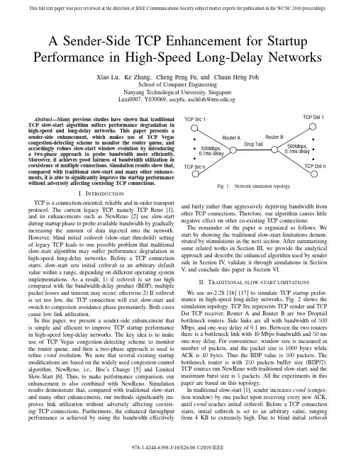
A Sender-Side TCP Enhancement for Startup Performance in High-Speed Long-Delay Networks Xiao Lu,Ke Zhang,Cheng Peng Fu,and Chuan Heng FohSchool of Computer EngineeringNanyang Technological University,SingaporeLuxi0007,Y030069,ascpfu,aschfoh@.sgAbstract—Many previous studies have shown that traditionalTCP slow-start algorithm suffers performance degradation in high-speed and long-delay networks.This paper presents a sender-side enhancement,which makes use of TCP Vegas congestion-detecting scheme to monitor the router queue,and accordingly refines slow-start window evolution by introducing a two-phase approach to probe bandwidth more efficiently. Moreover,it achieves good fairness of bandwidth utilization in coexistence of multiple connections.Simulation results show that, compared with traditional slow-start and many other enhance-ments,it is able to significantly improve the startup performance without adversely affecting coexisting TCP connections.I.I NTRODUCTIONTCP is a connection-oriented,reliable and in-order transport protocol.The current legacy TCP,namely TCP Reno[1], and its enhancements such as NewReno[2]use slow-start during startup phase to probe available bandwidth by gradually increasing the amount of data injected into the network. However,blind initial ssthresh(slow-start threshold)setting of legacy TCP leads to one possible problem that traditional slow-start algorithm may suffer performance degradation in high-speed long-delay networks.Before a TCP connection starts,slow-start sets initial ssthresh to an arbitrary default value within a range,depending on different operating system implementations.As a result,1)if ssthresh is set too high compared with the bandwidth-delay product(BDP),multiple packet losses and timeout may occur;otherwise2)If ssthresh is set too low,the TCP connection will exit slow-start and switch to congestion avoidance phase prematurely.Both cases cause low link utilization.In this paper,we present a sender-side enhancement that is simple and efficient to improve TCP startup performance in high-speed long-delay networks.The key idea is to make use of TCP Vegas congestion-detecting scheme to monitor the router queue,and then a two-phase approach is used to refine cwnd evolution.We note that several existing startup modifications are based on the widely used congestion control algorithm,NewReno,i.e.,Hoe’s Change[5]and Limited Slow-Start[6].Thus,to make performance comparison,our enhancement is also combined with NewReno.Simulation results demonstrate that,compared with traditional slow-start and many other enhancements,our methods significantly im-proves link utilization without adversely affecting coexist-ing TCP connections.Furthermore,the enhanced throughput performance is achieved by using the bandwidth effectivelyTCP Dst 1work simulation topology.and fairly rather than aggressively depriving bandwidth from other TCP connections.Therefore,our algorithm causes little negative effect on other co-existing TCP connections.The remainder of the paper is organized as follows.We start by showing the traditional slow-start limitations demon-strated by stimulations in the next section.After summarizing some related works in Section III,we provide the analytical approach and describe the enhanced algorithm used by sender side in Section IV,validate it through simulations in Section V,and conclude this paper in Section VI.II.T RADITIONAL SLOW-START LIMITATIONSWe use ns-2.28[16][17]to simulate TCP startup perfor-mance in high-speed long-delay networks.Fig.2shows the simulation topology.TCP Src represents TCP sender and TCP Dst TCP receiver.Router A and Router B are two Droptail bottleneck routers.Side links are all with bandwidth of500 Mbps,and one-way delay of0.1ms.Between the two routers there is a bottleneck link with40Mbps bandwidth and50ms one-way delay.For convenience,window size is measured in number of packets,and the packet size is1000bytes while ACK is40bytes.Thus the BDP value is500packets.The bottleneck router is with250packets buffer size(BDP/2). TCP sources run NewReno with traditional slow-start,and the maximum burst size is5packets.All the experiments in this paper are based on this topology.In traditional slow-start[1],sender increases cwnd(conges-tion window)by one packet upon receiving every new ACK, until cwnd reaches initial ssthresh.Before a TCP connection starts,initial ssthresh is set to an arbitrary value,ranging from4KB to extremely high.Due to blind initial ssthresh978-1-4244-6398-5/10/$26.00 ©2010 IEEE0 100 200 300 400 500 600 700800 0246810W i n d o w (p k t )Time (second)NewReno with SS (large ssth):NewReno with SS (small ssth):NewReno with Enhanced Start:BDP line:0 20 40 60 80 100 120 140 02 4 6 8 10B u f f e r (p k t )Time (second)Estimated queue at sender:Actual queue at router:Fig.2.Comparison of slow-start and Enhanced Start cwnd evolutions.setting,TCP suffers from low startup performance,especially in high-speed long-delay networks.Fig.2shows two typical cases where initial ssthresh mismatches the BDP.In the first case,ssthresh is set to 800packets,which is higher than the BDP represented by the dot line.We observe that the TCP connection,shown in the semi-dashed line,suffers many packets losses and long recovery time.In the second case,ssthresh is set to 32packets,which is much below the BDP.It shows that the TCP connection,expressed by the dashed line,exits slow-start and switches to congestion avoidance phase prematurely,resulting in a low bandwidth utilization.III.RELATED WORKOne critical reason of traditional slow-start performance suffering is that,sender lacks the ability to estimate the network condition properly.In recent years,various senderside modifications have been proposed to improve TCP startup performance.Some approaches aim to solve arbitrary ssthresh setting problem by setting ssthresh to some estimation value.In [5],Hoe proposed to set initial ssthresh to the estimated value of BDP obtained by using packet pair measurement.This method avoids the slow-start limitations,mentioned above,of enter-ing the congestion avoidance phase prematurely.However,attribute to cwnd increasing too fast towards the estimated BDP,Hoe’s Change may suffer temporary queue overflow and multiple losses when the bottleneck buffer is not big enough compared to the BDP.In [10],a measurement improves Hoe’s method by making use of multiple packet pairs to iteratively improve the estimate of ssthresh during startup progress.Nev-ertheless,simply using packet pairs cannot estimate available bandwidth paratively,Early Slow Start Exit (ESSE)[15]is robust against estimation errors.It adopts several approximations of pipesize estimation,based on the observation of few ACK arrival times,to set the initial ssthreshvalue and drastically reduces the packet drop rate.Another modified slow-start mechanism,called Adaptive Start [8],is proposed to make use of eligible rate estimation (ERE)mechanism [7],repeatedly resetting the slow-start ssthresh to a more appropriate value.This endues sender with the ability to grow cwnd efficiently without packet overflows.Agile Probing [4]uses a similar idea.However,an early transition form slow-start to Congestion Avoidance may occur to affect the throughput performance.Another approach improves startup performance by modify-ing the cwnd evolution.Smooth-Start [14]splits the slow-start into slow and fast phases to adjust the congestion window in different ways.It is capable of reducing packet loss during startup,however,it still does not address the question of how the ssthresh and the threshold that distinguishes the two phases should be set.Limited Slow-Start [6]introduces an additional threshold max ssthresh and modifies cwnd increase ly,when cwnd ≤max ssthresh ,cwnd doubles per RTT,the same as slow-start.When max ssthresh <cwnd ≤ssthresh ,cwnd is increased by a fixed amount of max ssthresh/2packets per RTT.This method reduces the number of drops during the startup,especially for TCP connections that is able to reach very large congestion window.However,max ssthresh is statically set before the TCP connection starts.IV.E NHANCEMENTSIn this section,we provide the analytical approach that is the fundamental scheme of our measurement.Then,the two-phase approach is introduced,followed by the description of the pseudo code.A.Analytical ApproachOur proposal,making use of TCP Vegas congestion-detecting scheme to monitor the router queue,attributes to that the congestion avoidance mechanism is based on changes in the estimated amount of extra data in the network rather than only on dropped segments.Past research work [3][12]has shown this detection,in terms of how many extra buffers the connection is occupying,leads to a more accurate estimation of network traffic condition.In Vegas,the throughput difference is calculated by:Diff =(Expected −Actual )=(cwndBaseRT T −cwnd RT T)where BaseRTT is the minimum of all measured RTT,and RTT is the actual round trip time of a tagged packet.Denote the backlog at router queue by N ,we have,RT T =BaseRT T +N/Actual.Rearrange the above equation,we deduce that,N =(cwndBaseRT T −cwnd RT T)×BaseRT T.(1)We note the Rerouting problem [11]this estimation method of TCP Vegas faces.Rerouting a path may change the prop-agation delay of the connection.More specifically,if a new route for the connection has a longer propagation delay,theconnection will not be able to tell whether the increase in the round trip delay is due to a congestion in the network or a change in the route.However,based on the fact that startup phase only last for a few seconds.Thus,Rerouting does not necessarily affect the startup performance.Therefore,during startup progress we can use(1)to estimate the backlog at router queue.This forms the basis to our enhancement of TCP startup behavior.B.Startup EnhancementThe key idea here is to detect the backlog status of the bot-tleneck routers with TCP Vegas congestion detection detecting schemefirst,and then modify the startup algorithm to properly react to the backlog.We propose a two-phase approach to adjust probing rate reacting to the changes of buildup queue in the router.A certain threshold of queue length can be used as a signal of queue being building up.The two phases of our measurement are for the queue buildup and non-buildup situation,respectively.After a certain threshold is set,changes of the estimated backlog can be used as a trigger to switch between two phases.Now,from(1),if N,the estimation of backlog at router queue,exceeds a certain threshold ofβpackets,we can assume that the router queue is building up and here we call it a congestive event.Each occurring times of congestion event is recorded as a new parameter at TCP sender every time the estimated backlog is greater than the threshold.Next,the two-phase approach is described in detail as follows.In Linear Increase Phase,when a TCP connection starts,the sender increases cwnd by one packet for every ACK received which the same as traditional slow-start.This process con-tinues until the queue length exceeds the thresholdβ,which marks a congestive event.Such a congestive event may due to either the exponential growth of cwnd being too fast for the bottleneck to cope with[4],or bandwidth fully utilization.For the both causes,network bottleneck capacity can be assumed reached.Thus,increasing cwnd in a conservative linear manner is more appropriate.We design cwnd to increment one packet every round-trip time in this phase.In the former cause of congestion event detection,by switching to increase linearly, sender can quickly drain the temporary queue to avoid buffer overflow and multiple losses.In the latter one,sender can assume that cwnd has already met the available bandwidth. Switching to linear increase actually have the same effect as congestion avoidance.This skillfully solves the ssthresh setting problem.In Adjustive Increase Phase,upon sensing that the router queue is drained,a sender enters this phase with the aim to adjust probing rate more intelligently.That is,every time the queue length draw back below the thresholdβ,implying under-utilization of bottleneck bandwidth,sender should speed up again its sending rate to probe the available bandwidth. However,the increase speed should be reduced because the spared bandwidth is less than before.Therefore,in this phase, the cwnd increase speed is set to half of that before the last congestive event.The startup phase exits when a packet loss event occurs. The pseudo code of our proposed scheme,which we called Enhanced Start,is given in the following.Algorithm1Enhanced Startthenssthresh=cwnd/2;/*switch to Congestion Avoidance Phase*/elseif(N≥β)thencwnd+=1/cwnd;for every ACK/*Linear Increase Phase*/elsecwnd+=max(1/cwnd,1/2exp{Congestion Event No});for every ACK/*Adjustive Increase Phase*/end ifend ifIn the above pseudo code,Congestion Event No indicates the number of congestion events occurred with its initial value set to0.Note that our algorithm is to probe eligible bandwidth intelligently during startup phase,when connection has no information about the network to set ssthresh.It is not executed after a timeout as ssthresh is no longer blindly set.V.P ERFORMANCE EVALUATIONIn this section,we present numerical results of Enhanced Start,compared with the tradition slow-start and other variant modifications,given different network environments with dis-similar parameter settings.We show the cwnd evolutions of Enhanced Start,and then comparisons of throughput achieve-ment.We also show the fairness and friendliness of our enhanced approach.A.Enhanced Start cwnd EvolutionFig.2shows Enhanced Start queue estimation and cwnd evolution.We see that the estimated queue at sender and the actual queue at router match quite well.By correctly estimat-ing the router queue,the sender increases cwnd in exponential-linear cycles,allowing cwnd to adaptively converge to the BDP in a timely manner.Our method also prevents the temporary queue from overflow when the buffer size is small.In Fig.3,we vary the value of threshold,β,to study the sensitivity of our algorithm.As can be seen from thefigure, surprisingly,varying the value does not cause much difference in cwnd evolutions.This means that the setting ofβis not a mainly decisive factor in the performance.However,as adopted in[9],we setβas3to be the test value for the remaininng experiments.To assess the capability of our measurement in the network with heterogenous stacks,we add a burst UDP cross-traffic set to10Mbps starting at thefirst second and stopping at the fifth second.Fig.4shows Enhanced Start queue estimation0 100 200 300 400 500 600 700800 0246810W i n d o w (p k t )Time (second)β= 2:β= 3:β= 5:β=10:β=15:β=20:BDP line:Fig.3.Enhanced Start cwnd evolution under different values of β.0 100 200 300 400 500600 0246810300250200 150 100 50 0W i n d o w (p k t )B u f f e r (p k t )Time (second)NewReno with Enhanced Start:Estimated queue at sender:Actual queue at router:BDP and full buffer line:Fig.4.Enhanced Start cwnd evolution under burst UDP cross-traffic (10Mbps starts at 1sec and stops at 5sec).and cwnd evolution under this scenario.We see that the queue estimation is accurate in approaching the actual queue.The cwnd evolution reveals that during the first second,the exponential growth behavior is just as traditional slow start.After the burst of UDP traffic,the sender detects the decrease of available bandwidth quickly through the backlogged queue,and accordingly,halves cwnd growth rate each time con-gestion event happens.After reaching the spared bandwidth,cwnd tends to maintain its value by growing smoothly.Then,right after the termination of UDP traffic flow,cwnd grows exponentially again to reach the BDP swiftly.Eventually,cwnd seizes the BDP quite accurately.This shows that Linear Increase Phase is able to avoid buffer overflow as the sudden decrease of available bandwidth,and avoid congestion when BDP is reached.While,Adjustive Increase Phase plays the main role in speeding up cwnd growth again when more available bandwidth is released.B.Throughput PerformanceThis subsection shows that the Enhanced Start significantly improves startup performance with regards to various band-width,one-way delay,and buffer size.To focus on the startup performance,we only calculate the throughput in the first 20seconds.Fig.5shows NewReno throughput with different startup algorithms under bottleneck bandwidth varying from 10Mbps to 150Mbps.We fix the bottleneck one-way delay to 50ms and buffer size to BDP/2.We compare NewReno with20 40 60 80 100 120 140T h r o u g h p u t (M b p s )Bandwidth (Mbps)Fig.5.NewReno (NR)throughput versus bottleneck bandwidth (first 20s).0 5 10 15 20 25 30 35 40102030405060708090100T h r o u g h p u t (M b p s )One-way delay (ms)Fig.6.NewReno (NR)throughput versus delay (first 20s).Enhanced Start (ES),Hoe’s Change (HC),Limited Slow-Start (LSS),slow-start with small ssthresh (32packets),slow-start with large ssthresh (extremely high),and TCP Vegas.It is shown that,NewReno with Enhanced Start and Hoe’s Change scale well with bandwidth.Other algorithms lack the ability to adapt to network bandwidth effectively,leading to poor throughput.Fig.6shows the throughput comparison under bottleneck one-way delay varying from 10ms to 100ms.We fix the bandwidth to 40Mbps and buffer size to BDP/2.The subtle changes in the throughput of NewReno with Enhanced Start and Hoe’s Change shows their ability to scale well with delay,while other startup algorithms suffer from performance degradation as delay increases.In Fig.7,we fix the bandwidth to 40Mbps and delay to 50ms,and vary the buffer size from 100packets to 300packets.It is evident that the only desirable throughput is achieved by Enhanced Start which keeps high throughput in all test cases.Also as is shown,when the buffer size is small,Hoe’s Change and Limited Slow-Start suffer severe performance degradation,while other startup algorithms fail to obtain a high throughput even with the help of increasing buffer size.C.Enhanced Start Fairness and FriendlinessFig.8shows the coexistence of multiple Enhanced Start and slow-start connections.We consider five NewReno con-nections,in which connections 1and 2are NewReno with slow-start (ssthresh 32packets)and connections 3,4,5are300280 260 240 220 200 180 160 140 120 100T h r o u g h p u t (M b p s )Buffer size (pkt)Fig.7.NewReno (NR)throughput versus buffer size (first 20s).NewReno with Enhanced Start.Connections 1,2,3,4start at 0second to investigate the effect of Enhanced Start and slow-start startup at the same time.Connection 5starts at 30th second to estimate the effect of Enhanced Start on existing TCP connections.It is shown that,comparatively NewReno behavior is more aggressive at the very beginning,while Enhanced Start starts up to make better use of the network bandwidth left unused by other connections.As time proceeds,the window sizes of the connections incline to approach to each ter,the presence of connection 5does not adversely affect coexisting TCP connections.After a burst,it joins the underway evolutions of the others.Finally,five connections converge to the same window size,which is around 100packet sizes,one fifth of the BDP.Each link shares its own part fairly.Enhanced Start shows good fairness to connections with same stack and friendliness to connections with NewReno stack.VI.C ONCLUSIONSIn this paper,we present a sender-side enhancement to improve TCP startup performance in high-speed long-delay networks by introducing a two-phase approach in startup process.It makes use of TCP Vegas congestion-detecting scheme to monitor the router queue,and refines congestion window evolution to quickly reach the eligible window sizes,meanwhile avoids multiple packet losses.Simulation results demonstrated that it is capable of significantly improving TCP startup performance without adversely affecting coexisting TCP connections and it is robust to small buffer size and long delay.Moreover,the performance improvement is achieved by making better use of the link bandwidth,and therefore,our algorithm causes little negative effect on other co-existing connections.R EFERENCES[1]V .Jacobson,“Congestion avoidance and control”,in Proc.SIG-COMM’88,Stanford,CA,pp.314-329.[2]S.Floyd,and T.henderson,“Newreno modification to TCP’s FastRecovery”,RFC 2582,April 1999.[3]L.S.Brakmo,S.W.O’Malley,et al.,“TCP Vegas:New Techniques forCongestion Detection and Avoidance”,in Proc.SIGCOMM’94,London,U.K.,Oct.1994,pp.24-35.0 50 100 150 200 250 300 350 40010203040 50 60 70W i n d o w s i z e (p k t )Time (second)NewReno 1 with SS:NewReno 2 with SS:NewReno 3 with ES:NewReno 4 with ES:NewReno 5 with ES:Fig.8.Co-existence of multiple Enhanced Start and slow-start connections.[4]R.Wang,K.Yamada,et al.,“TCP with Sender-Side Intelligence toHandle Evolution,Large,Leaky Pipes”,IEEE Journal on Selected Areas in Communications.V ol.23,No.2,February 2005.[5]J. C.Hoe,“Improving the startup behavior of a congestion controlscheme for TCP”,in Proc.SIGCOMM’96,pp.270-280.[6]S.Floyd,“Limited Slow-Start for TCP with Large Congestion Win-dows”,RFC 3742,March 2004.[7] C.Casetti,M.Gerla,S.Mascolo,M.Y .Sanadidi,and R.Wang,“TCP West-wood:bandwidth estimation for enhanced transport over wireless links”,In Proceedings of Mobicom 2001,Rome,Italy,July 2001.[8]Ren Wang Giowanni Pau,Kenshin Yamada,M.Y .Sanadidi,and MarioGerla,“Tcp startup Performance in Large Bandwidth Delay Networks”,in COM,April 2004.[9] C.P.Fu and S.C.Liew,“TCP Veno:TCP enhancement for transmissionover wireless access networks”,IEEE (JSAC)Journal of selected Areas in Communications,Feb 2003.[10]M.Aron and P.Druschel,“TCP:Improving startup dynamics by adaptivetimers and congestion control”,Technical Report (TR98-318),Depart-ment of Computer Science,Rice University,1998.[11]Richard ,Jean Walrand,and Venkat Anantharam,“Issues in TCPVegas”,Available at /hyongla,July 1998[12]Lawrence S.Brakmo,and Larry L.Peterson,“TCP Vegas:End to EndCongestion Avoidance on a Global Internet”,IEEE (JSAC)Journal of selected Areas in Communications,VOL.13,NO.8,OCTOBER 1995.[13]G.Hengartner,J.Bolliger,and T.Gross,“TCP Vegas revisited”,in Proc.IEEE INFOCOM,Mar 2000,pp.1546-1555.[14]Haining Wang and Care L.Williamson,“A New TCP congestion controlscheme:Smooth-start and dynamic recovery”,In Proceedings of IEEE MASCOTS98,Montreal,Canada,1998.[15]S.Giordano,G.Procissi,F.Russo,and Raffaello Secchi,“On the Use ofPipesize Estimators to Improve TCP Transient Behavior”,Proccedings of the IEEE International Conference on Communications ICC2005,V ol.1,pp.16-20,May 2005.[16]K.Fall and K.Varadhan,“The ns Manual”,/nsnam/ns/ns-documentation.html.[17]work Simulator./nsnam/ns。

adaptive_filters_theory_and_applications_2ndBrochureMore information from /doc/e9d77d4fdd3383c4ba4cd292.html /reports/2379637/Adaptive Filters. Theory and Applications. 2nd EditionDescription:This second edition of Adaptive Filters: Theory and Applications has been updated throughout to reflect the latest developments in this field; notably an increased coverage given to the practical applications of thetheory to illustrate the much broader range of adaptive filters applications developed in recent years. Thebook offers an easy to understand approach to the theory and application of adaptive filters by clearlyillustrating how the theory explained in earlier chapters of the book is modified for the various applications discussed in detail in later chapters. This integrated approach makes the book a valuable resource forgraduate students; and the inclusion of more advanced applications including antenna arrays and wireless communications makes it a suitable technical reference for engineers, practitioners and researchers.Key features:- Offers a thorough treatment of the theory of adaptive signal processing; incorporating new material ontransform domain, frequency domain, subband adaptive filters, acoustic echo cancellation and active noisecontrol.- Provides an in–depth study of applications which now includes extensive coverage of OFDM, MIMO andsmart antennas.- Contains exercises and computer simulation problems at the end of each chapter.- Includes a new companion website hosting MATLAB? simulation programs which complement thetheoretical analyses, enabling the reader to gain an in–depth understanding of the behaviours andproperties of the various adaptive algorithms.Contents:Preface xviiAcknowledgments xxi1 Introduction 11.1 Linear Filters 11.2 Adaptive Filters 21.3 Adaptive Filter Structures 31.4 Adaptation Approaches 71.5 Real and Complex Forms of Adaptive Filters 91.6 Applications 92 Discrete–Time Signals and Systems 282.1 Sequences and z–Transform 282.2 Parseval s Relation 322.3 System Function 332.4 Stochastic Processes 35Problems 443 Wiener Filters 483.1 Mean–Squared Error Criterion 483.2 Wiener Filter Transversal, Real–Valued Case 503.3 Principle of Orthogonality 553.4 Normalized Performance Function 573.5 Extension to Complex–Valued Case 583.6 Unconstrained Wiener Filters 613.7 Summary and Discussion 79Problems 804 Eigenanalysis and Performance Surface 904.1 Eigenvalues and Eigenvectors 904.2 Properties of Eigenvalues and Eigenvectors 914.3 Performance Surface 104Problems 1125 Search Methods 1195.1 Method of Steepest Descent 1205.2 Learning Curve 1265.3 Effect of Eigenvalue Spread 1305.4 Newton s Method 1315.5 An Alternative Interpretation of Newton s Algorithm 133 Problems 1356 LMS Algorithm 1396.1 Derivation of LMS Algorithm 1396.2 Average Tap–Weight Behavior of the LMS Algorithm 141 6.3 MSE Behavior of the LMS Algorithm 144 6.4 Computer Simulations 1566.5 Simplified LMS Algorithms 1676.6 Normalized LMS Algorithm 1706.7 Affine Projection LMS Algorithm 1736.8 Variable Step–Size LMS Algorithm 1776.9 LMS Algorithm for Complex–Valued Signals 1796.10 Beamforming (Revisited) 182Problems 190Appendix 6A: Derivation of Eq. (6.39) 2057 Transform Domain Adaptive Filters 2077.1 Overview of Transform Domain Adaptive Filters 2087.2 Band–Partitioning Property of Orthogonal Transforms 2107.3 Orthogonalization Property of Orthogonal Transforms 2117.4 Transform Domain LMS Algorithm 2137.5 Ideal LMS–Newton Algorithm and Its Relationship with TDLMS 2157.6 Selection of the Transform T 2167.7 Transforms 2297.8 Sliding Transforms 2307.9 Summary and Discussion 242Problems 2438 Block Implementation of Adaptive Filters 2518.1 Block LMS Algorithm 2528.2 Mathematical Background 2558.3 The FBLMS Algorithm 2608.4 The Partitioned FBLMS Algorithm 2678.5 Computer Simulations 276Problems 279Appendix 8A: Derivation of a Misadjustment Equation for the BLMS Algorithm 285 Appendix 8B: Derivation of Misadjustment Equations for the FBLMS Algorithms 288 9 Subband Adaptive Filters 2949.1 DFT Filter Banks 2959.2 Complementary Filter Banks 2999.3 Subband Adaptive Filter Structures 3039.4 Selection of Analysis and Synthesis Filters 3049.5 Computational Complexity 3079.6 Decimation Factor and Aliasing 3089.7 Low–Delay Analysis and Synthesis Filter Banks 3109.8 A Design Procedure for Subband Adaptive Filters 3139.9 An Example 316Problems 31910 IIR Adaptive Filters 32210.1 Output Error Method 32310.2 Equation Error Method 32710.3 Case Study I: IIR Adaptive Line Enhancement 33210.4 Case Study II: Equalizer Design for Magnetic Recording Channels 343 10.5 Concluding Remarks 349 Problems 35211 Lattice Filters 35511.1 Forward Linear Prediction 35511.2 Backward Linear Prediction 35711.3 Relationship Between Forward and Backward Predictors 35911.4 Prediction–Error Filters 35911.5 Properties of Prediction Errors 36011.6 Derivation of Lattice Structure 36211.7 Lattice as an Orthogonalization Transform 36711.8 Lattice Joint Process Estimator 36911.9 System Functions 37011.10 Conversions 37011.11 All–Pole Lattice Structure 37611.12 Pole–Zero Lattice Structure 37611.13 Adaptive Lattice Filter 37811.14 Autoregressive Modeling of Random Processes 38311.15 Adaptive Algorithms Based on Autoregressive Modeling 385 Problems 400Appendix 11A: Evaluation of E[ua(n)xT(n)K(n)x(n)uTa (n)] 407Appendix 11B: Evaluation of the parameter 40812 Method of Least–Squares 41012.1 Formulation of Least–Squares Estimation for a Linear Combiner 411 12.2 Principle of Orthogonality 41212.3 Projection Operator 41512.4 Standard Recursive Least–Squares Algorithm 41612.5 Convergence Behavior of the RLS Algorithm 421Problems 43013 Fast RLS Algorithms 43313.1 Least–Squares Forward Prediction 43413.2 Least–Squares Backward Prediction 43513.3 Least–Squares Lattice 43713.4 RLSL Algorithm 44013.5 FTRLS Algorithm 453Problems 46014 Tracking 46314.1 Formulation of the Tracking Problem 46314.2 Generalized Formulation of LMS Algorithm 46414.3 MSE Analysis of the Generalized LMS Algorithm 46514.4 Optimum Step–Size Parameters 46914.5 Comparisons of Conventional Algorithms 47114.6 Comparisons Based on Optimum Step–Size Parameters 475 14.7 VSLMS: An Algorithm with Optimum Tracking Behavior 477 14.8 RLS Algorithm with Variable Forgetting Factor 48514.9 Summary 486Problems 48815 Echo Cancellation 49215.1 The Problem Statement 49215.2 Structures and Adaptive Algorithms 49515.3 Double–Talk Detection 51215.4 Howling Suppression 52115.5 Stereophonic Acoustic Echo Cancellation 524Appendix 15A: Multitaper method 542Appendix 15B: Derivation of the Two–Channel Levinson Durbin Algorithm 54916 Active Noise Control 55116.1 Broadband Feedforward Single–Channel ANC 55316.2 Narrowband Feedforward Single–Channel ANC 55916.3 Feedback Single–Channel ANC 57316.4 Multichannel ANC Systems 577Appendix 16A: Derivation of Eq. (16.46) 582Appendix 16B: Derivation of Eq. (16.53) 58317 Synchronization and Equalization in Data Transmission Systems 584 17.1 Continuous Time Channel Model 585 17.2 Discrete Time Channel Model and Equalizer Structures 58917.3 Timing Recovery 59317.4 Equalizers Design and Performance Analysis 60617.5 Adaptation Algorithms 61717.6 Cyclic Equalization 61817.7 Joint Timing Recovery, Carrier Recovery, and Channel Equalization 628 17.8 Maximum Likelihood Detection 629 17.9 Soft Equalization 63117.10 Single–Input Multiple–Output Equalization 64317.11 Frequency Domain Equalization 64517.12 Blind Equalization 649Problems 65418 Sensor Array Processing 65918.1 Narrowband Sensor Arrays 66018.2 Broadband Sensor Arrays 67818.3 Robust Beamforming 683Problems 69219 Code Division Multiple Access Systems 69519.1 CDMA Signal Model 69519.2 Linear Detectors 69919.3 Adaptation Methods 707Problems 70920 OFDM and MIMO Communications 71120.1 OFDM Communication Systems 71120.2 MIMO Communication Systems 73020.3 MIMO OFDM 743Problems 743References 746Index 761Ordering:Order Online - /doc/e9d77d4fdd3383c4ba4cd292.html /reports/2379637/ Order by Fax - using the form belowOrder by Post - print the order form below and send toResearch and Markets,Guinness Centre,Taylors Lane,Dublin 8,Ireland.Fax Order FormTo place an order via fax simply print this form, fill in the information below and fax the completed form to 646-607-1907 (from USA) or +353-1-481-1716 (from Rest of World). If you have any questions please visit/doc/e9d77d4fdd3383c4ba4cd292.html /contact/Order Information Please verify that the product information is correct.Product Format Please select the product format and quantity you require:* Shipping/Handling is only charged once per order.Contact InformationPlease enter all the information below in BLOCK CAPITALSProduct Name:Adaptive Filters. Theory and Applications. 2nd Edition Web Address:/doc/e9d77d4fdd3383c4ba4cd292.html /reports/2379637/Office Code:SCLIZ46G QuantityHard Copy (HardBack):USD 128 + USD 28 Shipping/HandlingTitle:MrMrsDrMissMsProf First Name:Last Name:Email Address: *Job Title:Organisation:Address:City:Postal / Zip Code:Country:Phone Number:Fax Number:* Please refrain from using free email accounts when ordering (e.g. Yahoo, Hotmail, AOL)Payment InformationPlease indicate the payment method you would like to use by selecting the appropriate box.Please fax this form to:(646) 607-1907 or (646) 964-6609 - From USA+353-1-481-1716 or +353-1-653-1571 - From Rest of World Pay by credit card:You will receive an email with a link to a secure webpage to enter yourcredit card details.Pay by check:Please post the check, accompanied by this form, to:Research and Markets,Guinness Center,Taylors Lane,Dublin 8,Ireland.Pay by wire transfer:Please transfer funds to:Account number833 130 83Sort code98-53-30Swift codeULSBIE2D IBAN numberIE78ULSB98533083313083Bank Address Ulster Bank,27-35 Main Street,Blackrock,Co. Dublin,Ireland.If you have a Marketing Code please enter it below:Marketing Code:Please note that by ordering from Research and Markets you are agreeing to our Terms and Conditions at/doc/e9d77d4fdd3383c4ba4cd292.html /info/terms.asp。
非均匀区域油藏模拟负载平衡的分区并行算法
舒继武;赵金熙;周维四;张德富
【期刊名称】《软件学报》
【年(卷),期】1999(10)2
【摘要】基于分布式并行计算机系统,对一类非均匀区域的油藏数值模拟问题,采用了区域分解方法并行求解,给出了并行求解的负载平衡模型及区域负载平衡的一种有效分区算法,从而将这类油藏数值模拟问题均衡映射到并行环境中,高效地并行求解.在黑油油藏数值模拟并行软件的研究中,实验结果表明,该算法有利于提高加速比.【总页数】6页(P187-192)
【作者】舒继武;赵金熙;周维四;张德富
【作者单位】南京大学计算机软件新技术国家重点实验室,南京,210093;南京大学计算机科学与技术系,南京,210093;南京大学计算机软件新技术国家重点实验室,南京,210093;南京大学计算机科学与技术系,南京,210093;胜利油田地质科学研究院,东营,257000;南京大学计算机软件新技术国家重点实验室,南京,210093;南京大学计算机科学与技术系,南京,210093
【正文语种】中文
【中图分类】TP301
【相关文献】
1.云计算环境下基于非均匀窗口蚁群行为的负载平衡算法 [J], 张少辉;崔仲远;韩秋英
2.动态负载平衡的二维非结构网格DSMC并行算法研究 [J], 王学德;伍贻兆;夏健
3.解非均匀区域油藏模拟问题的一种有效并行计算方法 [J], 刘青昆;归丽忠;范建平;赵金熙;张德富
4.多层油藏模拟并行计算与负载平衡 [J], 刘青昆;舒继武;归丽忠;张德富
5.关于热传导方程有限差分区域分解并行算法精度的注记 [J], 万正苏;方春华;张再云
因版权原因,仅展示原文概要,查看原文内容请购买。
中图分类号:TN915.1 文献标识码:A 文章编号:1009-2552(2006)04-0053-03数字通信系统中自适应均衡技术的研究孙永梅,李 晖(大连交通大学电气信息学院,大连116028)摘 要:克服数字通信系统码间干扰的有效方法就是在接收端采用均衡技术。
文中给出了均衡问题的数学描述,综述了实现均衡的方法,讨论了基于LMS和基于RLS的自适应均衡算法,并通过MATLAB仿真比较了两类算法的性能。
关键词:数字通信;均衡;码间干扰;L MS算法;RLS算法The study of adaptive equalization in digital com munication system sSUN Yong mei,LI Hui(School of Electric and Information,Dalian Jiaotong University,Dalian116028,China) Abstract:Equalization in receivers is the effective method to reduce intersymbol interference.Mathe matical description of equalization is proposed,and equalization methods are summarized.Adaptive equalization algo rithms based on LMS and RLS are discussed,furthermore the performances of the algorithms are compared through MATLAB simulations.Key w ords:digital communication;equalization;intersymbol interference;LMS algorithm;RLS algorithm0 引言数字通信系统中,由于多径传输、信道衰落等影响,在接收端会产生严重的码间干扰(InterSymbol In terference,简称ISI),增大误码率。
AUnifiedAlgorithmforLoad-balancingAdaptiveScientificSimulations
KirkSchloegelandGeorgeKarypisandVipinKumar(kirk,karypis,kumar)@cs.umn.eduArmyHPCResearchCenterDepartmentofComputerScienceandEngineeringUniversityofMinnesota,Minneapolis,MN55455
August16,2000
AbstractAdaptivescientificsimulationsrequirethatperiodicrepartitioningoccurdynamicallythroughoutthecourseofthecomputation.Therepartitioningsshouldbecomputedsoastominimizeboththeinter-processorcommunicationsincurredduringtheiterativemesh-basedcomputationandthedatare-distributioncostsrequiredtobalancetheload.Recentlydevelopedschemesforcomputingrepartitioningsprovidetheuserwithonlyalimitedcontrolofthetradeoffsamongtheseobjectives.ThispaperdescribesanewUnifiedRepartitioningAlgorithmthatcantradeoffoneobjectivefortheotherdependentuponauser-definedparameterdescribingtherelativecostsoftheseobjectives.WeshowthattheUnifiedRepartitioningAlgorithmisabletoreducethepreciseoverheadsassociatedwithrepartitioningaswellasorbetterthanotherrepartitioningschemesforavarietyofproblems,regardlessoftherelativecostsofperforminginter-processorcommunicationanddataredistribution.Ourexperimentalresultsshowthatthisschemeisextremelyfastandscalabletolargeproblems.
Keywords:UnifiedRepartitioningAlgorithm,DynamicGraphPartitioning,MultilevelDiffusion,
Scratch-remap,AdaptiveMeshComputations
1IntroductionForlarge-scalescientificsimulations,thecomputationalrequirementsoftechniquesrelyingongloballyrefinedmeshesbecomeveryhigh,especiallyasthecomplexityandsizeoftheproblemsincrease.Bylocallyrefiningandde-refiningthemesheithertocaptureflow-fieldphenomenaofinterest[1]ortoaccountforvariationsinerrors[14],adaptivemethodsmakestandardcomputationalmethodsmorecosteffective.Theefficientexecutionofsuchadaptivescientificsimulationsonparallelcomputersrequiresaperiodicrepartitioningoftheunderlyingcomputationalmesh.Theserepartitioningsshouldminimizeboththeinter-processorcommunicationsincurredintheiterativemesh-basedcomputationandthedataredistributioncostsrequiredtobalancetheload.Recentlydevelopedschemesforcomputingrepartitioningsprovidetheuserwithonlyalimitedcontrolofthetradeoffsamongthesetwoobjectives.ThispaperdescribesanewUnifiedRepartitioningAlgorithmthatcantradeoffoneobjectivefortheotherdependentuponauser-definedparameterdescribingtherelativecostsoftheseobjectives.
Figure1illustratesthestepsinvolvedintheexecutionofadaptivemesh-basedsimulationsonparallelcom-puters.Initially,themeshisdistributedamongtheprocessors.Anumberofiterationsofthesimulation
0-7803-9802-5/2000/$10.00(c)2000IEEE.
1Compute a New PartitioningIterative Mesh-based ComputationRedistribute DataMesh Adaptation
Figure1:Adiagramillustratingtheexecutionofadaptivescientificsimulationsonhighperformanceparallelcomputers.
areperformedinparallel,afterwhichmeshadaptationoccurs.Here,eachprocessorrefinesandde-refinesitslocalregionsofthemeshresultinginsomeamountofloadimbalance.Anewpartitioningbasedontheadaptedmeshiscomputedtore-balancetheload,andthenthemeshisredistributedamongtheprocessors,respectively.Thesimulationcanthencontinueforanothernumberofiterationsuntileithermoremeshadaptationisrequiredorthesimulationterminates.
Ifweconsidereachroundofexecutinganumberofiterationsofthesimulation,meshadaptation,andload-balancingtobeanepoch,thentheruntimeofanepochcanbedescribedby
(tcomp+f(|Ecut|))n+trepart+g(|Vmove
|)(1)
wherenisthenumberofiterationsexecuted,tcompisthetimetoperformthecomputationforasingle
iterationofthesimulation,f(|Ecut
|)isthetimetoperformthecommunicationsrequiredforasingleiteration
ofthesimulation,andtrepartandg(|Vmove
|)representthetimesrequiredtocomputethenewpartitioning
andtoredistributethedataaccordingly.Here,theinter-processorcommunicationtimeisdescribedasafunctionoftheedge-cutofthepartitioningandthedataredistributiontimeisdescribedasafunctionofthetotalamountofdatathatisrequiredtobemovedinordertorealizethenewpartitioning.
AdaptiverepartitioningaffectsallofthetermsinEquation1.Howwellthenewpartitioningisbalancedinfluencestcomp.Theinter-processorcommunicationstimeisdependentontheedge-cutofthenewpar-
titioning.Thedataredistributiontimeisdependentonthetotalamountofdatathatisrequiredtobemovedinordertorealizethenewpartitioning.Recentlydevelopedadaptiverepartitioningschemes[4,5,11,12,13,14,15,16,17,20,21,22,23,24,25]tendtobeveryfast,especiallycomparedtothetimerequiredtoperformevenasingleiterationofatypicalscientificsimulation.Theyalsotendtobalancethenewpartitioningtowithinafewpercentofoptimal.Hence,wecanignorebothtrepartandtcomp