外文翻译--汽车转向系统
- 格式:doc
- 大小:104.00 KB
- 文档页数:12
附录A 外文文献Electric Power Steering system1.HistoryIn automobile development course, Steering system experienced four stages of development: from the initial mechanical Steering system (for your DNS setting Steering, abbreviation ) development for Hydraulic Steering system (Hydraulic Power Steering, abbreviation HPS), then again appeared electronically controlled Hydraulic Steering system (Electro Hydraulic Power Steering, abbreviation EHPS) and Electric Power Steering system (Steering, room Power as EPS). Assemble mechanical steering system of car parking and low-speed driving, when the driver's steering control burden too heavy, in order to solve this problem, the American GM in the 1950s took the lead in the car hydraulic steering system. But, hydraulic steering system can't juggle vehicles to speed portability and high speed, so the steering stability Koyo in Japan in 1983, with the company introduced the application of speed sensing function of hydraulic steering system. This new type of steering system can provide speed increased with the decreasing steering, but complicated structure, cost is higher, and cannot overcome hydraulic system itself has many shortcomings, is a cross between a hydraulic steering and electric power steering the transition between the products. In 1988, Japan Suzuki company first in small cars equipped with Cervo Koyo company development on the steering column, power type electric power steering system; In 1990, Japan Honda NSX in sports car company adopted self-developed rack power type electric power steering system, henceforth unveils the electric power steering in cars applications history2.Working principleElectric power steering system are as follows: first, the working principle, torque sensor measured on steering wheel drivers on the manipulation of the moment, the wheel speed sensors detect the vehicle driving speed, then present the two signals to ECU; According to the built-in control strategy: ECU, calculates the ideal target booster torque, into current instructions to motor; Then, the power generated by the torque motor slowdown institutions amplification on steering system in mechanical manipulation of the moment, and the driver together to overcome resistance torque, realize to the vehicle steering.3. Working processElectric power steering system as traditional hydraulic system alternative products has entered into the auto manufacturing. And had predicted instead, EPS not only applicable to small cars, and some for 12V medium vehicle installed electric system.EPS system includes the following components:The torque sensor: detection steering wheel motion and vehicle motion situation;Electronic control units: according to provide the torque sensor the size of the signal computing power;Motor: according to the electronic control units; turn power output value generation Reduction gear: improve motor power, and produce turn it sends to steering mechanism.Other vehicle system control algorithm input information is provided by the car CAN bus (for example steering Angle and bus speed, etc.). Motor drive also need other information, such as motor rotor position and the three-phase motor sensor (current sensor provided). Motor control by four MOSFET, due to micro controller cannot direct drive of large gate capacitance, MOSFET using drive IC form needed the interface, for safety, complete motor control system must implement monitoring, motor control system integration in PCB, usually contains a relay, the relay use, as the main switch under the condition of the fault detection, disconnect motor and electronic control units.Micro control device must control EPS system and have brushless motor. Micro control device according to the torque sensor provide needed the steering wheel torque information, forming a current control loop. In order to improve the security of the system level, the micro control device should have an on-board oscillator, so even in external oscillator malfunction case, also ensure micro control device performance, also should have chip watchdog. Infineon XC886 integration of the company all the important micro control device component, other safety features for through the software to realize, if must implement safety standards IEC61508 industries, you have to finish all kinds of diagnosis and self-inspection task and increase micro control device work load. At present different customers use of torque sensor and rotor position sensor difference is very big. They use different measuring principle, such as decomposing machine, magnetic resonance device, based on the integration of giant magnet or stance sensor.The role of power levels is switch electric current. The power level has two main functions: drive IC control and protection MOSFET, MOSFET itself and to be responsible for switch currents. MOSFET and partition.Micro control device PWM output port provides driver current and voltage is too low, can't directly connected with MOSFET screen realization. Drive IC role is to provide enough current, the grid to charge for MOSFET, so that in the and discharge 20kHz conditions, and ensure the normal realization switch for discretion side provides the high bar source voltage MOSFET, ensure that you get the low conduction resistance. If the high side MOSFET in open state, to source potential close battery level. Want to make MOSFET arrived at nominal conduction resistance, gate to higher than 8V source voltage. MOSFET completely conduction needed the most ideal voltage is required, therefore 10V or above a grid of potential than battery voltage 10V is higher. Charge pump is to ensure that the function to the largest extent reduce MOSFET power (even if low battery voltage conditions) circuit.The other key charge pump design according to different characteristics that can be PWM pattern request, achieve extremely low (low to 1%) and high rate of 390v (high to 100%). Drive IC another important function is testing, avoid damage to short-circuit mosfets, affected MOSFET will be closed, diagnosis submitted to micro control device.附录B 外文文献的中文翻译电动助力转向系统1.发展历史在汽车的发展历程中,转向系统经历了四个发展阶段:从最初的机械式转向系统(Manual Steering,简称MS)发展为液压助力转向系统(Hydraulic Power Steering,简称HPS),然后又出现了电控液压助力转向系统(Electro Hydraulic Power Steering,简称EHPS)和电动助力转向系统(Electric Power Steering,简称EPS)。
附录A 外文文献Overview ofDevelopment on Vehicle EPS SystemAbstractThe currentdevelopment of an electric power steering(EPS) system in an automobile is explicated. The structure, types and characteristics of electric power steering system are introduced. The modeling technologies for electric power steering system and control strategies are analyzed and compared. The development trend of electric power steering system in an automobile is also discussed. It is pointed that the electric power steering technology is one orientation ofpower steering technologies in the future, and whichwill occupy a predominantposition in power steering field.Key words:Automobile; Electric power steering system; Development trend1EPS system types and characteristics1.1EPS system classificationThe early development of EPS system is low in steering type car。
Automobile Transmissions and Power Steering Automobiles, trucks, buses, and tractors all depend on transmissions to deliver power from the engine to the wheels, The gasoline and diesel engines that power these vehicles cannot be connected directly to the wheels, because the engines must keep turning at a certain seed to keepfrom stalling. Also, different amount of torque (turning force) must be delivered to the wheels atdifferent times. A large amount of force is needed to get a car moving from a standstill. Less force is needed to keep the car moving once it is rolling. Going up a hill of driving at high speed requires still other amount of force. It is the job of the transmission to deliver the particularamount of force that is needed. The transmission also allows a motor vehicle to back up-----gasoline and diesel engines can run in only one direction, but the transmission can reverse thedirection of the force. And when a car stops, the transmission lets the engine keep running without moving the wheels.The heart of any transmission——even an automatic one—is a set of gears. Gears do notchange the power of an engine, but they can increase the torque by decreasing the speed. They canalso increase the speed by decreasing the torque.The automobile transmission uses a series of gears which enables the engine to continue tovehicle’’s speed is altered. Setting an automobile in operate at maximum efficiency when the vehiclevehicle’’s weight. This motion requires a large amount of power to overcome the inertia of the vehicleprocess requires high engine speed, needed for high power, and a gradual increase in a vehicle’sspeed to avoid a jerky start. To do this, a low gear ratio is allows the crankshaft to revolve several times in order to turn the real axle once. The low gear ratio is used for starting, climbing steep slops, and other situations in which maximum power is required .As power needs are reduced, a second, higher gear ratio is used which rotates the rear axle with fewer revolutions of the crankshaft. As the car’s speed increases, successively higher gear ratios are used until the drive from the engine to the rear wheels passes through the transmission without reduction. Two principle types of transmission are used, manual and automatic.The manual transmission system permits the driver to select the desired gear ratio bymanipulating a shift lever. Besides the forward speed gears, additional gearing is incorporated topermit the vehicle to operate in reverse. Manually operated passenger car transmission used in the United States and Canada usually have there speeds forward and one in reverse. Trucks, tractors, buses, and other heavy-duty vehicles have as many as 10 forward speeds and 2 in reverse. These units are basically five-speed transmissions with a two-speed auxiliary gearbox. Transmission that are to be shifted with the vehicle in motion incorporate synchromesh units to prevent gears from clashing as they are meshed. The synchromesh unit synchronizes the speed of the gears so that they revolve at the same speed as they slide into engagement.The automatic transmission system changes gear ratios automatically in response to changesin engine speed or throttle setting. The use of automatic transmissions increased tremendouslyafter World War Ⅱ, and they are installed in more than half of the automobile produced in the United States. Automobiles equipped with an automatic transmission have a control lever which allows the driver to select neutral, low, drive, and reverse. The engine is started in neutral, and the lever is moved to “drivedrive”” position the drive”” for normal operation when moving forward. In “drivevehicles can accelerate from rest to maximum speed by simply depressing the accelerator. Thelow”” position prevent the transmission from shifting out of the lower gear ratios.“lowIt is used for climbing steep grades, in mud, or at other tomes when maximum power ispark”” position, which locks the transmission to prevent a parked car needed. Some units have a “parkfrom rolling. The automatic transmission makes it easier to drive a car, but it is less efficient than a manually shifted unit and increase gasoline consumption. For this reason, the automatic transmission is not as common in Europe, where economy of operation is a prime sales factor.Four basic types of automatic transmissions have been developed to the point where they have been installed in production vehicles. The first consists of a standard mechanical transmission and clutch which is automatically shifted by pneumatic, hydraulic or electric power units. The second type uses a hydraulic torque converter plus a planetary gear system to increase engine torque. The third system combines a hydraulic coupling with an automatically shifted mechanical gearbox to provide torque amplification. The fourth type uses one or more stages of hydraulic torque conversion to provide torque multiplication.Automatic transmission shift in response to signals from speed sensing and throttle position sensors. The units incorporating hydraulic torque converters use the hydraulic fluid, under pressure, to engage and disengage planetary gear trains.Power steering system 也是汽车重要的一部分,The car of today is larger and heavier than earlier cars; the tyres are wider, further apart and inflated to lower pressures .In addition, the trend of development has been to place more than half the weight on the front wheels, especially the weight of the engine , which itself is larger and heavier than in the early days.To make cars easier to steer, the gear ratio in the steering box at the end of the steering column was changed to that turning the wheel required less torque, but this increased the number of turns of the steering wheel required on modern cars without power steering compared to 2.5 or 3 turns for cars built before 1940. Modern cars with power steering only require about three turns.Power assisted steering was first developed in the 1920s; one of the first devices was developed by an engineer at Pierce Arrow, an American make of luxury cars. The Cadillac division of General Motors was going to offer power steering as optional equipment on some models in the early 1930s, but the depression interfered with development. During World War Ⅱ power steering was fitted to military vehicles; in 1952 Chrysler began offering it , and it is now standard equipment on many of the biggest American cars .Electric devices were tried , but power steering today is always hydraulic , with oil pressure of perhaps 1000 psi (70kg/cm2) maintained by a pump driven by the engineer of the car . The system is a servomechanism, or servo loop, which makes a correction to compensate for the torque applied to the steering wheel by the driver. It consists of an actuator and a control valve. The actuator is a hydraulic cylinder with a piston, or ram, which is free to travel in either direction from the center. The function of the control valve is to respond to the torque from the steering wheel by actuating smaller valves at each end of the cylinder. The system is designed to assist the steering linkage, rather than to replace it, and it does not do all of the work of steering , but leaves some of it for the driver. Thus if the hydraulics fail the car can still be steered , though with greater effort, and at all times the feel of the road is mechanically transmitted from the front wheels to the hands of the hands of the driver on the steering wheel, an essential element of safe driving. The power steering makes a positive contribution to safe driving in that if the driver hits a small obstacle in the road or has a flat tyre at speed, the power unit makes it easier to keep the car under control. Many large cars fitted with wide, stiff radial ply tyres would be nearly impossible to steerat parking speeds without power steering.Hydrostatic systems, designed for off-the-road vehicles, are exception to some of this, because they dispense with the steering column and the steering box , and the steering wheel and the steered wheels are connected only by hydraulic tubes or hoses.The power steering system includes a reservoir to hold the oil. Oil pressure is always provided when the engine is running, but when the system is at rest, that is when the steering wheel is not being turned, equal pressure is available to each side of the piston in the actuator, so that it does not move.There are basically two types of power steering system: those which have the control valve located within the steering box, in which case it is usually a rotary valve, and those in which the valve is integral with actuator, when it is an axial spool valve.汽车传动系与动力转向装置轿车、卡车、公交车以及拖拉机都靠汽车传动系将动力从发动机输送到车轮上。
The Mazda Speed Sensing Computerised 4-Wheel Steering System.Three and a half decades ago, two young Mazda designers arrived at a far-sighted andwell-calculated conclusion that was quite revolutionary for the time. In their technical presentation at the October 26, 1962 Japanese Automotive Engineers' Society Technical Conference, Dr Tadashi Okada and engineer Toshiaki summarised their arduous research concerning vehicle dynamics as follows.1. The basic difference in the characteristics of oversteer and understeer lies in themagnitude of time delay and response.2. a vehicle that is stable under high speed must possess understeer characteristics3. the rear wheel tyre reflects heavily on the stability and4. a major improvement on control and stability may be anticipated by means of theautomatic rear wheel steering system.The conclusions and formulations presented by these two engineers established the foundation for Mazda's present-day reputed suspension technology. Over years of dedicated research and development expertise, their original discoveries and theories have contributed to some of the most significant achievements within the recent history of automotive chassis engineering, incorporated by Mazda within its series production products. These developments include the twin trapezoidal link rear suspension, first employed in the original front-wheel drive Mazda 323 (1980) and the Mazda 626 (1982), and then perfected within the updated Mazda 626; the award winning Dynamic Tracking Suspension System of the second generation Mazda RX-7 (1985); and the elaborate E-link rear suspension of the new Mazda 929 (1987).While various external forces and loads are exerted to the rear wheels of a vehicle as it combats the elements of the law of motion as defined by Sir Isaac Newton, these new suspension systems convert those forces into "4WS effects" which positively aid in vehicle stability and agility.The Mazda designers' and engineers' ultimate goal was still a positive measure to generate forces for positive controls; a Four-Wheel Steering system.In 1983, Mazda astonished the automotive world with the introduction of an engineering concept car, the MX-02, exhibited at the Tokyo Motor Show. This four-door Sedan, with generous passenger accommodation on an unusually long wheelbase, incorporated among its numerous advanced features a true 4WS system that aided high-speed stability as well as its low-speed manoeuvring. The degree of rear wheel steering was determined by the measurement of both front wheel steering angle and vehicle speed, by means of a central computer unit.The MX-02 was followed by another exciting concept car; the MX-03, first exhibited at the Frankfurt Motor Show in September 1985. This sleek four seat futuristic coupe of the 1990s combined a refined electronically-controlled 4WS system with a continually varyingtorque-split, four-wheel drive system and a powerful three-rotary engine.Mazda Electronically -Controlled Four-Wheel Steering System:A Beneficial TechnologyMazda's electronically-controlled, vehicle-speed-sensing Four-Wheel Steering System (4WS) steers the rear wheels in a direction and to a degree most suited to a corresponding vehicle speed range. The system is mechanically and hydraulically actuated, producing greatly enhanced stability, and within certain parameters, agility.The driver of a Mazda 4WS-equipped car derives five strategic benefits, over and above the conventional vehicle chassis.1. Superior cornering stability2. Improved steering responsiveness and precision3. High-speed straightline stability4. Notable improvement in rapid lane-changing manoeuvres5. Smaller turning radius and tight-space manoeuvrability at low vehicle speed rangeThe most outstanding advantage of the Mazda 4WS is that it contributes to a notable reduction in driver fatigue over high-speed and extended travelling. This is achieved by optimally:1. reducing the response delay to steering input and action and2. eliminating the vehicle's excessive reaction to steering inputIn essence, by providing the optimum solution to the phenomena researched by the two young Mazda engineers in the early sixties - by the method advocated by them - the 4WS system has emerged as a fully beneficial technology.Strategic ConstructionThe Mazda 4WS consists of a rack-and-pinion front steering system that is hydraulically assisted by a twin-tandem pump main power source, with an overall steering ratio of 14.2:1. The rear wheel steering mechanism is also hydraulically assisted by the main pump and electronically controlled - according to the front steering angle and vehicle speed. The rear steering shaft extends from the rack bar of the front steering gear assembly to the rear steering-phase control unit.The rear steering system is comprised of the input end of the rear steering shaft, vehicle speed sensors, a steering-phase control unit (determining direction and degree), a power cylinder and an output rod. A centering lock spring is incorporated, which locks the rear system in a neutral (straightforward) position in the event of hydraulic failure. Additionally, a solenoid valve that disengages hydraulic assist (thereby activating the centering lock spring) in case of anelectrical failure is included.The 4WS system varies the phase and ratio of the rear-wheel steering to the front wheels, according to the vehicle speed. It steers the rear wheels toward the opposite phase (direction) of the front wheel during speeds less than 35km/h (22mph) for a tighter turn and "neutralizes" them (to a straightforward direction, as in a conventional two-wheel steering principle) at35km/h (22mph). Above that speed, the system steers toward the same phase-direction as the front wheels, thereby generating an increased cornering force for stability. The maximun steering angle of the rear wheels extends 5 degrees to either left or right, a measurement that Mazda has determined to be optimally effective and natural to human sensitivity.Primary Components1. Vehicle speed sensors Interpret speedometer shelf revolutions and send signal to theelectronic computer unit. two sensors, one within the speedometer and the other atthe transmission output, are used to crosscheck the other for accuracy and failsafemeasures.2. Steering phase control unit* Conveys to the power steering cylinder booster valve thedirection and stroke of rear wheel steering by the combined movement of the control yoke angle and bevel gear revolutions.3. Electric stepper motor Performs altering of the yoke angle and bevel gear phasing4. Rear steering shaft Transmits front wheel steering angle by turning the small bevelgear in the steering phase control unit, which rotates the main bevel gear in theassembly.5. Control valve Feeds hydraulic pressure to the steering actuator, according to thephase and stroke required for appropriate rear wheel steering.6. Hydraulic power cylinder Operates the output rod by hydraulic pressure and steersthe rear wheels. It locks the rear wheels in a "neutral" (straightforward) position withthe centering lock spring, which is activated by a solenoid valve in case of failure toensure a normal 2WS function for the vehicle.7. Hydraulic pump. Provides hydraulic pressure to both the front and rear steeringsystems.Details of Steering Phase Control UnitThe steering phase control unit alters the direction and degree of rear wheel steering. It consists of a stepper motor that controls the rear steering ratio, a control yoke, a swing arm, a main bevel gear engaged to the rear steering shaft via a small bevel gear, and a control rod connected to the control valve. It operates:a. Opposite phase (direction) steering under 35km/h (22mph)1. Control Yoke is at an angle activated by the stepper motor2. Front wheels are steered to the right. The small bevel gear is rotated in direction X bythe rotation of the rear steering shaft. The small bevel gear, in turn, rotates the mainbevel gear.3. Rotation of the main bevel gear causes movement of the control rod toward thecontrol valve.4. Input rod of the control valve is pushed to the right, according to the degree of thecontrol rod's movement (determined by the disposition of the swing arm), which ispositioned to move in an upward direction, to the right. The rear wheels are thussteered to the left, in an opposite direction to the front wheels.5. As the angle of the control yoke is increased in direction A as vehicle speeddecreases, the rear-to-front steering ratio proportionately increases and the vehicle'ssteering lock tightens.b. Same phase (direction) over 35km/h (22mph)The operation of this phase is the reverse of the opposite phase one, because the control yoke is angled toward "positive" in this vehicle speed range, as illustrated. The phasing of the swing arm, yoke rod and bevel gear steers the rear wheels toward the right-the same direction as the front wheels.c. Neutral phase, at 35km/h (22mph) The control yoke's angle is horizontal (neutral). Thus, the input rod is not affected, even if the control rod is moved with the rotation of the bevel gear unit. As a result, the rear wheels are not steered in this mode.Power CylinderThe movement of the input rod of the control valve unit is transmitted to the power cylinder'sspool. The spool's displacement to the sleeve causes a pressure difference between the right and left side chambers in the hydraulic power cylinder. The pressure difference overcomes the output shaft load and initiates sleeve movement. The sleeve-power rod assembly is moved in the direction of the input rod by a proportionate degree. The output rod transmits steering action to the tie rod on either end of the rear wheel steering control-mechanism unit, thereby steering the rear wheels.Fail-Safe MeasuresThe system automatically counteracts possible causes of failure, both electronic and hydraulic. In either case, the centering lock spring housed in the steering system unit returns the output rods in the "neutral" straightforward position, essentially alternating the entire steering system to a conventional 2WS principle.Specifically, if a hydraulic defect should render a reduction in pressure level (by a movement malfunction or a broken driving belt), the rear wheel steering mechanism is automatically locked in a neutral position, activating a low-level warning light.In the event of an electrical failure, such would be detected by a self-diagnostic circuit integrated within the 4WS control unit, which stimulates a solenoid valve and then neutralizes hydraulic pressure and return lines, thereby alternating the system again to that of a 2WS principle. Henceforth, the warning light referencing the 4WS system within the main instrument display is activated, indicating a system failure.翻译马自达公司的速度感应四轮转向系统三十五年前,两个马自达设计师提出了一个远见的、有计算认为是相当革命性的结论。
汽车零部件英语
发动机Engine
作用:提供动力,驱动汽车运动。
变速箱Transmission
作用:控制发动机的输出转速,使汽车在不同速度下行驶。
刹车系统Brake System
作用:控制汽车的速度和停车。
转向系统Steering System
作用:控制汽车的转向方向。
悬挂系统Suspension System
作用:保证车身平稳行驶,减少震动。
电气系统Electrical System
作用:为汽车提供电力,驱动灯光、音响、电动窗等设备。
供油系统Fuel System
作用:将燃料输送到发动机,保证发动机正常燃烧。
冷却系统Cooling System
作用:保持发动机在适宜的温度范围内工作。
排气系统Exhaust System
作用:将发动机燃烧后产生的废气排出。
点火系统Ignition System
作用:提供火花点燃混合气体。
传动系统Drive Train
作用:将发动机的动力传输到车轮上。
轮胎与制动片Tires and Brakes
作用:提供与路面的接触,同时制动片负责刹车。
燃油系统Fuel Injection System
作用:将燃油以适当的量喷射到发动机内部。
空调与暖气系统Air Conditioning and Heating System 作用:调节车内温度,提供舒适的乘坐环境。
排放控制系统Emission Control System
作用:控制和减少尾气排放,保护环境。
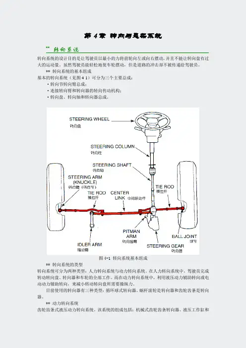
第4章转向与悬架系统** 转向系统转向系统的设计目的是让驾驶员以最小的力将前轮向左或向右摆动,并且不能让转向盘有过大的运动量。
虽然驾驶员能轻松地使车轮摆动,但是道路的冲击却不被传递给驾驶员。
** 转向系统的基本组成基本的转向系统(见图4-1)可分为三个主要总成:·转向节转向臂总成;·连接转向臂和转向器的转向传动机构;·转向盘、转向轴和转向器总成。
图4-1 转向系统基本组成** 转向系统的类型转向系统可分为两种类型:人力转向系统与动力转向系统。
在人力转向系统中,驾驶员完成转动转向盘、转向器和车轮的全部工作。
而在动力转向系统中,利用液压动力辅助转向或电动动力辅助转向,来减小转动转向盘所需要操纵力。
目前使用的转向器有三种类型:循环球式转向器、蜗杆滚轮是转向器和齿轮齿条是转向器。
** 动力转向系统齿轮齿条式液压动力转向系统。
该系统的组成包括:机械式齿轮齿条转向器、液压工作缸和活塞、旋转滑阀、油泵、限压阀和储液罐(见图4-2)。
图4-2一种带有旋转滑阀的齿轮齿条式液压动力转向系统电控液压动力转向系统——Servotronic。
Servotronic是一种液压助力会随着行车速度而变化的的电子控制齿轮齿条动力转向系统。
在低速时,可获得最大助力。
随着车速的增加液压助力减小。
因此,Servotronic是一种速敏式动力转向系统。
Servotronic的组成部件有:车速表、ECU、齿轮传统式液压转向器、储液罐、电控液压变换器和油泵(见图4-3)。
图4-3 Servotronic——一种电控液压动力转向系统电动转向——Servoletric。
使用Servoletric电动转向系统(见图4-4),转向助力由电子控制的电动机所产生。
只有在需要时,才接通电动机。
通过一根带有力矩传感器的扭杆来测量驾驶员所加的转向力矩,另外还通过车速传感器来测量车速。
这两个信号被送往ECU。
ECU利用程序图计算所需的转向力矩和力的传递方向,然后给电动机发送相关输出信号。
S¯a dhan¯a V ol.33,Part5,October2008,pp.581–590.©Printed in IndiaDSP-based electric power assisted steering using BLDC motorR MURUGAN,S NANDAKUMAR and M S MOHIYADEENBharat Electronics Limited,Nandambakkam,Chennai600089e-mail:muruganr@bel.co.in;nandakumars@bel.co.in;mohiyadeenms@bel.co.inAbstract.This paper introduces a design and implementation of electricallyassisted power steering(EAS)using BLDC motor for a vehicle.The control archi-tecture consists of two layers of control,namely the vehicle speed associated controland the torque assist control.In the higher level of control architecture,the vehiclespeed controller works as an assistance level controller for the steering effort.Inthe lower level,the torque controller gives the effort level control.This has beenrealized by torque sensor and vehicle sensor interfaced in the DSP.For implement-ing in the system,a DSP-based BLDC motor controller with three-phase invertermodule is specially designed using Hall-effect sensor feedback and a single dc-linkcurrent sensor.This work is implemented in a Light Commercial Vehicle havinga recirculating ball type gear.This is for thefirst time(EAS)being implementedfor this type of vehicle any where in the world.Generally,EAS having clutch todisconnect the motor in high speed or abnormal conditions from the gear box.Inthis implementation the motor is directly coupled to gearbox without clutch and allabnormalities are handled by the processor.This is implemented without modify-ing the vehicle supply system like changing the existing alternator or rating of thebattery and using the existing sensors.The design is such a way that the feel of thedriver assistance can be varied easily at any time.The performance of the controlsystem is experimentally verified and it is tested in one of the Light CommercialVehicle(LCV).Keywords.BLDC motor;EAS;steering.1.IntroductionPower steering is a system for reducing the steering effort on vehicles by using external source to assist in turning the wheels.Most new generation vehicles now have power steering, owing to the trends toward greater vehicle mass and wider tires,all increase the steering effort needed.Modern vehicles would be difficult to maneuver at low speeds(e.g.when parking) without assistance.Most power steering systems work by using a belt-driven pump to provide hydraulic pressure to the system.This hydraulic pressure is generated by a pump which is driven by the vehicle’s engine.While the power steering is not used,i.e.driving in a straight line,twin hydraulic lines provide equal pressure to both sides of the steering wheel gear.581582R Murugan,S Nandakumar and M S MohiyadeenWhen torque is applied to the steering wheel,the hydraulic lines provide unequal pressures and hence assist in turning the wheels in the intended direction.Electric Power Steering systems use electric components with no hydraulic systems at all.Sensors detect the motion and torque of the steering column and a computer module applies assistive power via an electric motor coupled directly to either the steering gear or steering column.This allows varying amounts of assistance to be applied depending on driving conditions.In the event of component failure,a mechanical linkage such as a rack and pinion serves as a back-up in a manner similar to that of hydraulic systems.Electric systems have an advantage in fuel efficiency because there is no hydraulic pump constantly running. Their other big advantage is the elimination of a belt-driven engine accessory,and several high-pressure hydraulic hoses between the hydraulic pump,mounted on the engine,and the steering gear,mounted on the chassis.This greatly simplifies manufacturing.The demand of electrically assisted power steering(EAS)has rapidly increased in past few years because of energy savings compared to Hydraulic Power Steering(HPS).Alternating current(ac)motors are designed to be highly efficient and easily controlled with modern power circuitry.Because of the developments in switching techniques,it is quite feasible to use ac motors with a battery supply as source.The traditional worm gear driven dc motor system is constrained by the limitations of the dc motor brushes and size of the motor for the same torque of BLDC.In this case BLDC motor has been used as an actuator in the application for electric power steering.The BLDC motor provides high torque and easy control(Chan &Fang2002;Chu et al2001;Desai&Emadi2005;Jun-Uk Chu et al2004;Kevin Brown et al1990;NamhunKim et al2007).The basic mechanical properties of the vehicle are essentially invariant among all of the available brands.The electrically assisted power steering system consists of BLDC motor mounted to the frame of the steering column and coupled to the wheels through a worm speed reducer.Electrically assisted power steering is shown in figure1.An electrically assisted power steering is composed of several parts such as torque sensor, engine speed sensor,vehicle speed sensor,steering column,torsion bar and electronic control unit.Figure1.Electrically assisted power steering.DSP-based electric power assisted steering using BLDC motor583 Torque sensor output gives the torque difference to be developed by the motor to reduce the effort required by the driver while he is steering.Engine speed signal is required to start the assistance only when the engine is ON in order to save the battery life.Vehicle speed signal is required to control the assistance developed by the motor(for the same level of torque signal)at various vehicle speed,as assistance requirement comes down as speed of the vehicle increases.The control architecture consists of two layers of control,namely the assistance level control and the torque control.In the higher level of control architecture,vehicle speed signal works as a reference for controlling the assistance to be developed by the motor.In the inner layer torque sensor signal performs generation of torque.The torque output from motor is a function of torque sensor signal and it depends on the torque difference between the steering wheel and the wheel.The vehicle speed signal and engine speed signals are pulses with variable frequency.For system implementation,a DSP-based BLDC motor controller with three-phase inverter module is specially designed using Hall-effect sensor feedback and a single dc-link current sensor.The torque and Back EMF equations of BLDC motor are similar to that of dc motor.The current sensing is ensured by a low cost shunt resistor and used for over-current protection and current feedback.The current control is achieved by PID controller and pulse width modulation(PWM) signals with varying duty rates.Hall-effect sensors are available to detect rotor shaft position, used for electronic commutation,motor speed and direction of rotation.2.Hardware architectureA block diagram of the power assisted steering is illustrated infigure2.The electrically assisted power steering system in a vehicle consists of the following parts.a.Digital signal processorb.Driver and protection cardc.Three phase inverterd.BLDC motor with Hall sensore.Reduction gear and sensors.Figure2.Block diagram of EAS.584R Murugan,S Nandakumar and M S MohiyadeenFigure3.DSP and protection card.2.1ProcessorThe DSP used for control and computation is TMS320F24XX.The processor is a single chip solution based on40MIPS,16bitfixed point DSP core with several associated peripherals such as Pulse Width Modulation generator(PWM)and Analog to Digital Converter(ADC) BPRA0551997;SPRU160C1999;SPRU161C1999.2.2Driver and protection circuitThe selected MOSFET Driver is from IR family.The PWM signals coming from the DSP are combined with protection logics and connected to MOSFET driver.The output of the driver is directly connected to the MOSFET switches through series gate resistor.The current sensing is done by the low cost shunt resistor.The voltage drop is processed with analog amplifier and connected to ADC module and used for current feedback and over-current protection.The protection card used here is shown in thefigure3.2.3Three phase inverter moduleThe three phase inverter module is developed by using MOSFETs with low ON state drop and high switching frequency.The three-phase inverter card used is shown infigure4.Figure4.MOSFET card.DSP-based electric power assisted steering using BLDC motor585Figure5.BLDC motor equivalent circuit.2.4BLDC motor with Hall sensorThe equivalent circuit of a BLDC motor is shown infigure5.The BLDC motor used here has8magnetic pole pairs on the rotor and a three-phase star connected windings on stator. The voltage equation of BLDC motor can be represented as⎡⎣V aV bV c⎤⎦=⎡⎣R000R000R⎤⎦⎡⎣i ai bi c⎤⎦+⎡⎣L000L000L⎤⎦ddt⎡⎣i ai bi c⎤⎦+⎡⎣e ae be c⎤⎦(1)R=Phase resistanceL=Phase inductanceV a,V b,V c=Phase voltagesI a,i b,i c=Phase currentse a,e b,e c=Back EMFs.The generated motor torque is given byT=e a i a+e b i b+e c i cω,(2)whereωis motor angular velocity.The motor is equipped with three Hall effect sensors.The Hall sensors produce three180◦(electrical)overlapping signals as shown in thefigure6.Thus it is providing six mandatory commutation points.The Hall sensor outputs are directly connected to processor and it generate the necessary switching sequence as per commutation.2.5Gear box and sensing circuitsThe BLDC motor is connected to a reduction gear system as shown infigure7.It drives the wheel.The torque difference between the steering wheel and wheel is sensed by a torsion bar.The output of the torsion bar is sensed by the torque sensor.The output of the torque sensor is directly connected to ADC for processing.586R Murugan,S Nandakumar and M S MohiyadeenFigure6.Hall sensor wave form.3.Controller design3.1Effort level controlThe electrically assisted power steering(EAS)incorporates a brushless electric motor located on the steering column,on the pinion that assists the driver when rmation like engine speed,and torque required are transmitted in real time to a DSP which deter-mines the optimal degree of assistance the electric motor should apply.Figure8shows the effort required by the driver without assistance and with assistance for a vehicle at static.Electrically assisted power steering eliminates the need for hydraulicfluids and complicated mechanical components(such as servo pumps),hydraulic lines,belts and pulleys,which add weight and volume.By eliminating the hydraulic pump,the EAS can operate without the help of the engine.Unlike a conventional hydraulic system,the EAS consumes energy only when providing assistance.The control algorithm for the electrically assisted steering system is shown infigure9.The effective torque and velocity control of a BLDC motor is based on relatively simple torque and Back EMF equations,which are similar to those of the DC motor.Figure7.Gear box with motor.DSP-based electric power assisted steering using BLDC motor587Figure8.Effort curve. During any120degree interval of phase current,I the instantaneous power(P)being converted from electrical to mechanical isP=ωT e=2EI(3)T e=Electromagnetic torqueE=Induced EMF per phase.The‘2’in this equation arises from the fact that two-phase are conducting.E=2NphB g Lrω,per phase induced emf.(4)Nph=Number of winding turns per phaseB g=Rotor magneticfield densityL=Length of the rotorr=Internal radius of rotor.Figure9.Control algorithms.588R Murugan,S Nandakumar and M S MohiyadeenUsing the above expression the electromagnetic torque is given by,T e=4NphBgLrI=KφI(5)K=Torque constantφ=Flux per pole pair.The system takes torque reference(I−ref)and feedback line current(Ifb)as input,produces duty-cycle reference as output.This is actually a PI controller.The following equation is implementedD−cycle=K p(I−ref−If b)+K pT i(I−ref−If b)dt,(6)Kp=Proportional constantT i=Time constant.Limiters are there atfinal controller output.Duty cycle reference is clamped to the peak of the saw tooth carrier wave.Current control is achieved by Pulse Width Modulation(fixed frequency20kHz)signals with varying duty cycles.PWM width is determined by comparing the measured actual current with the desired reference current.To sum up,the Back EMF is directly proportional to the motor velocity and the torque production is almost directly proportional to the phase current.In this control scheme,torque production follows the principle that current shouldflow in only two of the three phases at a time.Only one current at a time needs to be controlled so that only one current sensor is necessary.The positioning of the current sensor allows the use of a low cost resistor as a shunt.3.2Assistance level controlFigure10shows the effort required to be produced by the motor for various vehicle speeds.Variable steering assistance(higher at low vehicle speed and lower at high vehiclespeed),Figure10.Boost curve for various speeds.DSP-based electric power assisted steering using BLDC motor589Figure11.Driving effort outputfrom EAS.which improves drivability and active safety.This has been implemented by sensing the vehicle speed and accordingly modifies the effort to be produced by the electric motor by controlling reference to the controller.4.Experimental resultsIn this section,the result is presented(figure11)to ensure the validity of the proposed method at static driving.From the abovefigure,we can see that the effort required by the driver is almost constant entire steering wheel rotation.The effort reduction comes around75%.The motor is selected such that the cogging torque is very less.The maximum peak cogging torque of the motor used at10rpm is0·0056Nm compared to peak torque of2·45Nm.The acceleration and deceleration of the motor is done in such a way that the driver does not feel the torque ripple in his hand.The torque ripple generally felt at low speed,here the system in a loop such that the system is always in acceleration/deceleration phase,so feel of torque ripple is less.Further to above,the mechanical system itself is in variable gear ratio and it has inherent torque variation more than the motor torque ripple produced by the motor.Hence the driver is not able to feel the torque ripple compared with EAS ON mode and EAS OFF mode.From this result,it is seen that the proposed EAS has performed as expected.Maximum torque required(manual):32NmTorque required during power assistance:8NmPercentage assistance provided:75%Average current consumption:8A5.ConclusionFor equivalent power steering efficiency,electrically assisted power steering improves fuel consumption by4percent or more compared to conventional hydraulic systems.The elimina-tion of hydraulicfluids is also more environmentally friendly for End of Life Vehicle(ELV) consideration.Electronic data management(wheel angle,vehicle speed,etc.)can be used to fine-tune the power steering parameters,enhancing the car drivability.Variable steering assis-tance improves drivability and active safety.Steering force feedback incorporates controlled re-centre positioning of the steering wheel and active damping of highway vibration.590R Murugan,S Nandakumar and M S MohiyadeenReferencesBPRA055March1997DSP Solutions for BLDC motors.Literature number:Texas Instruments Europe Chan Lie-Tong Yan F,Shao-Yuan Fang2002In-Wheel permanent-magnet brushless dc motor drive for an electric bicycle.IEEE Trans.Energy Conversion17(2):229–232Chu C L,Tsai M C,Chen H Y2001Torque control of brushless DC motors applied to electric vehicles.IEEE Trans.on1–5Desai,Ali Emadi2005A novel digital control technique for brushless DC motor drives:Current control.IEEE Trans.326–331Jun-Uk Chu,In-Hyuk Moon,Gi-Won Choi,Jei-Cheong Ryu,Mu-Seong Mun2004Design of BLDC motor controller for electric power wheelchair.IEEE Trans.94–95Kevin E Brown,Rafael M Inigo,Barry W Johnson1990Design,implementation,and testing of an adaptable optimal controller for an electric wheelchair.IEEE Trans.on Industry Application26(6): 1144–1157NamhunKim,Hamid A Toliyat,Issa M Panahi,Min-Huei Kim2007BLDC motor control algorithm for low-cost industrial applications.IEEE Trans.1400SPRU160C June1999TMS320F/C24x DSP Controllers reference guide CPU and instruction set.Literature number:Texas Instruments EuropeSPRU161C June1999TMS320F/C240DSP controllers reference guide—Peripheral library and spe-cific devices.Literature number:Texas Instruments Europe。
附录A 外文文献Electric Power Steering system1.HistoryIn automobile development course, Steering system experienced four stages of development: from the initial mechanical Steering system (for your DNS setting Steering, abbreviation ) development for Hydraulic Steering system (Hydraulic Power Steering, abbreviation HPS), then again appeared electronically controlled Hydraulic Steering system (Electro Hydraulic Power Steering, abbreviation EHPS) and Electric Power Steering system (Steering, room Power as EPS). Assemble mechanical steering system of car parking and low-speed driving, when the driver's steering control burden too heavy, in order to solve this problem, the American GM in the 1950s took the lead in the car hydraulic steering system. But, hydraulic steering system can't juggle vehicles to speed portability and high speed, so the steering stability Koyo in Japan in 1983, with the company introduced the application of speed sensing function of hydraulic steering system. This new type of steering system can provide speed increased with the decreasing steering, but complicated structure, cost is higher,and cannot overcome hydraulic system itself has many shortcomings, is a cross between a hydraulic steering and electric power steering the transition between the products. In 1988, Japan Suzuki company first in small cars equipped with Cervo Koyo company development on the steering column, power type electric power steering system; In 1990, Japan Honda NSX in sports car company adopted self-developed rack power type electric power steering system, henceforth unveils the electric power steering in cars applications history2.Working principleElectric power steering system are as follows: first, the working principle, torque sensor measured on steering wheel drivers on the manipulation of the moment, the wheel speed sensors detect the vehicle driving speed, then present the two signals to ECU; According to the built-in control strategy: ECU, calculates the ideal target booster torque, into current instructions to motor; Then, the power generated by the torque motor slowdown institutions amplification on steering system in mechanical manipulation of the moment, and the driver together to overcome resistance torque, realize to the vehicle steering.3. Working processElectric power steering system as traditional hydraulic system alternative products has entered into the auto manufacturing. And had predicted instead, EPS not only applicable to small cars, and some for 12V medium vehicle installed electric system.EPS system includes the following components:The torque sensor: detection steering wheel motion and vehicle motion situation;Electronic control units: according to provide the torque sensor the size of the signal computing power;Motor: according to the electronic control units; turn power output value generationReduction gear: improve motor power, and produce turn it sends to steering mechanism.Other vehicle system control algorithm input information is provided by the car CAN bus (for example steering Angle and bus speed, etc.). Motor drive also need other information, such as motor rotor position and the three-phase motor sensor (current sensor provided). Motor control by four MOSFET, due to micro controller cannot direct drive of large gate capacitance, MOSFET using drive IC form needed the interface, for safety, complete motor control system must implement monitoring,motor control system integration in PCB, usually contains a relay, the relay use, as the main switch under the condition of the fault detection, disconnect motor and electronic control units.Micro control device must control EPS system and have brushless motor. Micro control device according to the torque sensor provide needed the steering wheel torque information, forming a current control loop. In order to improve the security of the system level, the micro control device should have an on-board oscillator, so even in external oscillator malfunction case, also ensure micro control device performance, also should have chip watchdog. Infineon XC886 integration of the company all the important micro control device component, other safety features for through the software to realize, if must implement safety standards IEC61508 industries, you have to finish all kinds of diagnosis and self-inspection task and increase micro control device work load. At present different customers use of torque sensor and rotor position sensor difference is very big. They use different measuring principle, such as decomposing machine, magnetic resonance device, based on the integration of giant magnet or stance sensor.The role of power levels is switch electric current. The power level has two main functions: drive IC control andprotection MOSFET, MOSFET itself and to be responsible for switch currents. MOSFET and partition.Micro control device PWM output port provides driver current and voltage is too low, can't directly connected with MOSFET screen realization. Drive IC role is to provide enough current, the grid to charge for MOSFET, so that in the and discharge 20kHz conditions, and ensure the normal realization switch for discretion side provides the high bar source voltage MOSFET, ensure that you get the low conduction resistance. If the high side MOSFET in open state, to source potential close battery level. Want to make MOSFET arrived at nominal conduction resistance, gate to higher than 8V source voltage. MOSFET completely conduction needed the most ideal voltage is required, therefore 10V or above a grid of potential than battery voltage 10V is higher. Charge pump is to ensure that the function to the largest extent reduce MOSFET power (even if low battery voltage conditions) circuit.The other key charge pump design according to different characteristics that can be PWM pattern request, achieve extremely low (low to 1%) and high rate of 390v (high to 100%). Drive IC another important function is testing, avoid damage toshort-circuit mosfets, affected MOSFET will be closed, diagnosis submitted to micro control device.附录B 外文文献的中文翻译电动助力转向系统1.发展历史在汽车的发展历程中,转向系统经历了四个发展阶段:从最初的机械式转向系统(Manual Steering,简称MS)发展为液压助力转向系统(Hydraulic Power Steering,简称HPS),然后又出现了电控液压助力转向系统(Electro Hydraulic Power Steering,简称EHPS)和电动助力转向系统(Electric Power Steering,简称EPS)。
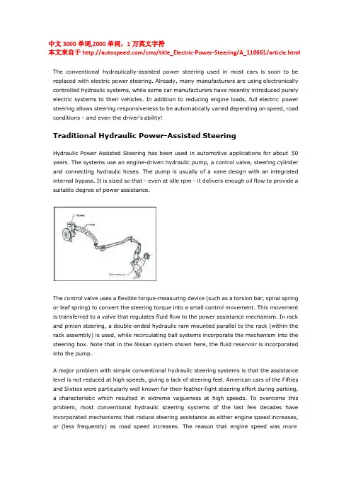
中文3000单词,2000单词,1万英文字符本文来自于/cms/title_Electric-Power-Steering/A_110661/article.htmlThe conventional hydraulically-assisted power steering used in most cars is soon to be replaced with electric power steering. Already, many manufacturers are using electronically controlled hydraulic systems, while some car manufacturers have recently introduced purely electric systems to their vehicles. In addition to reducing engine loads, full electric power steering allows steering responsiveness to be automatically varied depending on speed, road conditions - and even the driver's ability!Traditional Hydraulic Power-Assisted SteeringHydraulic Power Assisted Steering has been used in automotive applications for about 50 years. The systems use an engine-driven hydraulic pump, a control valve, steering cylinder and connecting hydraulic hoses. The pump is usually of a vane design with an integrated internal bypass. It is sized so that - even at idle rpm - it delivers enough oil flow to provide a suitable degree of power assistance.The control valve uses a flexible torque-measuring device (such as a torsion bar, spiral spring or leaf spring) to convert the steering torque into a small control movement. This movement is transferred to a valve that regulates fluid flow to the power assistance mechanism. In rack and pinion steering, a double-ended hydraulic ram mounted parallel to the rack (within the rack assembly) is used, while recirculating ball systems incorporate the mechanism into the steering box. Note that in the Nissan system shown here, the fluid reservoir is incorporated into the pump.A major problem with simple conventional hydraulic steering systems is that the assistance level is not reduced at high speeds, giving a lack of steering feel. American cars of the Fifties and Sixties were particularly well known for their feather-light steering effort during parking, a characteristic which resulted in extreme vagueness at high speeds. To overcome this problem, most conventional hydraulic steering systems of the last few decades have incorporated mechanisms that reduce steering assistance as either engine speed increases, or (less frequently) as road speed increases. The reason that engine speed was morecommonly used as is that such a system can remain purely hydraulic, whereas using road speed as the control variable requires the use of an electronic system.Electronically-Controlled Hydraulic SteeringThe introduction of electronic speedometers - and subsequently, full engine management - meant that an electronic road speed signal became available, allowing the widespread use of electronically-controlled hydraulic steering systems. These vary steering effort depending on road speed and also, in some cases, other factors as well.A number of different hydraulic approaches to regulating steering assistance are used. These are:Flow ControlA solenoid valve is located on the discharge port of the hydraulic pump. Electronic control is used to control the solenoid valve opening, so regulating the fluid flow. The flow is reduced at high road speeds, reducing the degree of assistance provided.Cylinder BypassA solenoid valve and associated bypass line is located between the two chambers of the hydraulic cylinder, allowing the reduction of the pressure difference between them. The solenoid valve opening is controlled electronically, its opening being greater at high road speeds. This reduces the degree of assistance that is provided.Hydraulic Reaction ForceA hydraulic force is enabled that works against the power assistance. As speed increases, the reaction force is increased. Since fluid flow to the power cylinder is not affected, the steering response rate can remain high without reductions occurring in feel.In their electronically-controlled hydraulic steering system, Hyundai use an ECU equipped with an 8-bit microprocessor. Two major inputs - vehicle speed and the speed of steering wheel movement - are used. From these inputs, the ECU determines the driving condition and via a 3-dimensional look-up map, provides the appropriate current flow to a hydraulic solenoid valve.Three different driving conditions are recognised:Parking - maximum current is supplied to the solenoid valve, resulting in maximum steering assistance.High Speed - minimum current is supplied to the solenoid valve, resulting in minimum steering assistance.Evasive Steering - a large and sudden steering input causes the ECU to supply a current to the solenoid proportional to the speed of the steering input.There are plenty of speed-sensitive hydraulic steering systems around. This diagram shows the layout of a Mazda MX6 system where the degree of assistance is based on road speed and steering angle. (1) steering wheel; (2) steering shaft; (3) intermediate shaft; (4) steering gear assembly; (5) pressure hose; (6) return hose; (7) oil pump; (8) solenoid valve; (9) ECU;(10)reserve tank; (11) steering angle sensor; (12) check connector.Hybrid Hydraulic/Electric Power Steering SystemsHybrid hydraulic steering systems use an electric motor to drive the hydraulic pump, rather than having the pump driven directly by the engine. This approach allows the steering effort to be easily controlled by varying the pump speed. Because flow can be better matched to actual requirements, the power drain is reduced - fuel economy savings of up to 0.2 litres/100 km are possible.The control approach that is taken can be of three types -Driving Mode - where driving conditions (such as city, country, highway, etc) are automatically judged with appropriate levels of assistance then provided.Steering Wheel Input Mode- where the speed of the steering wheel movement is used to determine the degree of assistance required.Steering Load Mode - where demand for power assistance is indicated by the counter-pressure of the hydraulic fluid, sensed through variations in the motor current load.The General Motors hybrid hydraulic steering system shown here uses Steering Load Mode to determine the actual steering loads and so the degree of assistance that needs to be provided. The 3-phase brushless DC motor (12) is supplied power by the Motor Power Circuit. The EHPS control provides a control signal to the Motor Power Circuit in response to input signals fromthe motor angle sensor, motor current sensor and battery current sensor as well as operating system voltage. The temperature of the hydraulic fluid is also monitored.Electric Power-Assisted SteeringElectric Power-Assisted Steering completely replaces the hydraulic system that previously has always been associated with power steering. Electric power steering systems assist driver effort by the use of an electric motor which acts through a reversible gearbox and in some cases, also an electromagnetic clutch. An electronic control unit determines the degree of assistance that is rendered.Electric power steering has some significant advantages over any form of conventional hydraulic steering, both for the owner of the car and its manufacturer. The reduction in engine load of an electric power steering system (it can be as low as 4 watts when the car is being driven in a straight line) means that the fuel economy of a car equipped with electric power steering is very similar to that of a car with no form of power steering. Analyses provided by manufacturers of electric power steering systems indicate potential fuel savings of 4-8 per cent over cars equipped with conventional hydraulic steering, with the lighter mass of an electric power steering also having an impact here. The independence of the system from engine operation also means that should the engine stall, steering assistance does not change.From a manufacturer's perspective, using electric power steering reduces assembly line time, allows the easy software tuning of the steering assistance characteristics to suit a variety of cars (eg a sports car or a limousine - more on this in a minute), and has the potential to improve reliability - 53 per cent of all power steering warranty claims are from pump and hose problems. Environmental gains are also possible from the decreased production and disposal of hydraulic fluid (worldwide, an estimated 40 million litres of power steering fluid was in use in 1995) and from the decreased requirement for the non-recyclable polymers used in hydraulic hoses.Features BenefitsEngine independence Reduced engine power drainImproved fuel economy andaccelerationInstant-on power steeringAssistance available even should theengine stallSimplified packagingElimination of pump, hoses, fluid, drivebeltand pulleyEnvironmental compatibilityReduced massModular design and integrated controller Reduced assembly timeDesign and packaging flexibility Multi vehicle use Design and packaging flexibilitySoftware tuning Wide assistance rangeIn-vehicle laptop PC tuningTuning process reduced from monthsto hoursCost-effective advanced features Variable effort steering,Assisted return to centreSteering damping capabilityDepending on the location of the electric assist unit, the electric drive assistance can be transmitted to the steering mechanism by a number of means. These are:Method Electric Assist UnitLocationPower TransmissionPinion assist Under the dashboard on thesteering columnMotor > worm gear > column shaft >pinion shaftOn the steering rack inputpinionMotor > gear train > pinion shaftRack assist On the steering rack Motor > ball screw > rack shaftOn a second pinion on thesteering rackMotor > planetary geartrain > anothershaft pinion > rack shaftSo, How Good is Your Driving?One of the most interesting aspects of electric power steering is the ability that the manufacturer has to tune the system's responsiveness. As indicated earlier, this allows the easy software matching of a single electric power steering to applications as diverse as a two-seater sports car or luxury sedan, but it also means that system responsiveness can be made to vary in different driving situations in the one car. When this approach is taken, the input by the driver of a certain amount of steering lock does not always result in the same degree of assistance - should the ECU determine that such a steering movement is notappropriate for the conditions, the steering assistance may be reduced or the steering input even actively resisted!As an indication of the far-reaching implications of this, Honda has very recently developed an electric power steering system that estimates the skill of the driver and provides steering assistance to match. In the Honda system, a 'driver skill estimation device' is used, having inputs from:• a GPS system(!);• a vehicle speed sensor;• a steering sensor that provides information on steering angular speed, angular acceleration and torque input;• a brake pedal sensor that detects braking stroke, speed and force;• a throttle pedal sensor that detects accelerator stroke and speed;• a yaw rate sensor;• a road friction estimate input.The road friction estimate is determined by the undertaking of an audio frequency analysis of the sound of the tyres on the road! From this it is determined whether the road is dry, wet, snowy, powdery snow or icy. (Note that while the GPS and yaw rate inputs are included in the Honda patent of the system, Honda state that the system can still work effectively without them.)The 'driver skill estimation device' analyses the actual path taken by the vehicle and compares this with a computed target trajectory. Using this and data on the vehicle wheelbase, the distance that the front and rear wheels are from the vehicle centre of gravity (and other factors), the system awards the driver an ability that varies on five levels from "very poor" to "very good". A very good driver is rewarded with very little steering force resistance (the driver gets what he or she asks for), while a poor driver will encounter steering that actively does not allow major steering inputs to be made at high speed.According to Honda, this allows the skilled driver to "positively control the turning behaviour of the vehicle so as to briskly manoeuvre the vehicle. Conversely, if the vehicle operator is not skilled, the control system produces a reaction which prevents the vehicle operator from over-reacting to the vehicle response, and (so) stabilises the vehicle."But you have to wonder what happens when a 'very poor' driver suddenly needs to swerve around a child that runs out onto the road.... However, the Honda system does provide a very strong indication of the direction that electric power steering systems can be expected to follow in the future.在大量车上使用传统的液压助力转向系统很快将被电子控制转向系统代替。
转向英文名词Steering (control)system转向系统Manual steering system 机械转向系Parallelogram steering linkage平行四边形转向传动机构Rack and pinion steering system 齿轮齿条式转向系Steering system for independent suspension 独立悬架转向系统Steering system for nonindependent suspension 非独立悬架转向系统Steering linkage转向传动机构Tie rod linkage/Ackerman geometry梯形机构Single tie rod type tie rod linkage整体式梯形机构PS system=power steering system, power-assisted steering system动力转向系统Integral PS system 整体式动力转向系统Booster type power steering system助力式动力转向系统Semi-integral power steering system半整体式动力转向系统Ackerman Jeantaud steering 阿克曼-金特式转向Steering (knuckle)arm转向节臂Tie rod(转向)横拉杆Idler arm随动臂Steering idler arm转向随动臂Relay rod, center rod 中继杆Rack 齿条Steering wheel 转向盘Steering shaft 转向轴Steering control mechanism 转向操纵机构Steering gear, steering gearbox, steering mechanism 转向器Pitman arm 转向摇臂Steering knuckle, steering (axle) swivel, steering (axle)stub,axle stub 转向节Drag link, drag rod 直拉杆PS pump=power steering pump 动力转向油泵Integral power steering gear 整体式动力转向器Power steering gear 动力转向器Power cylinder转向动力缸转向传动机构Steering Linkage(Mechanism) Parallelogram steering linkage 平行四边形转向传动机构Rack and pinion steering linkage 齿轮齿条式转向传动机构Boll joint 球节Steering (knuckle) arm 转向节臂Steering gear 转向器Pitman arm, drop arm, steering gear arm, steering lever转向节臂Inner tie rod 内横拉杆Inner tie rod end joint 横拉杆内接头Idler arm随动臂Bracket(所动臂)支架Mounting bracket 安装支架Relay rod, center link, centre link, connecting rod 中继杆Adjusting sleeve, adjusting tube(横拉杆)调节臂Outer tie rod 外横拉杆Outer tie rod end joint 横拉杆外接头Steering knuckle转向节Tie rod, tie bar, track横拉杆Steering tie rod 转向横拉杆Tie rod clamp 横拉杆夹Grease fitting 滑脂嘴Bearing 轴承Ball cup, ball socket, ball cap球碗,球头座Ball stud ,ball pivot, ball pin 球头消Full-ball stud 全球式球头销Joint housing 接头壳Compression spring 压缩弹簧Steering shock absorber 转向减振器转向操纵机构Steering Control(Mechanism) Intermediate shaft 中间轴Dust cover 防尘罩Universal joint 万向节Steering universal joint 转向万向节Steering column 转向管柱Upper column cover 管柱上罩Lower column cover 管柱下罩Combination switch 组合开关Steering wheel 转向盘4-spoke wheel 四辐条转向盘3-spoke wheel 三辐条转向盘Rim 盘缘,盘辐Spoke 辐条Ignition/starter switch 点火/起动机开关Air bag module 安全气囊组件Wheel pad with SRC airbag带安全气囊的转向盘盖Steering wheel pad, wheel pad 转向盘盖Upper bracket 上支架Key cylinder 钥匙筒 Column tube 管柱管Clamp 固定夹Bushing 衬套Main shaft 主轴Steering inner articulated shaft 转向传动轴可倾斜式转向管柱Tilt Steering Column Manual tilt手动倾斜Power tile 电动倾斜Upper column tube 上管柱管Lower column tube 下管柱管Main shaft (转向轴)主轴Pawl stopper 棘爪止动器Tilt lever retainer 倾斜度调整手柄保持板Tension spring 拉簧Tilt lever 倾斜度调整手柄Pawl wheel, ratchet wheel 棘轮Steering bolt 转向螺栓Compression spring 压紧弹簧Tilt switch 倾斜开关Tilt motor 倾斜电动机Tilt ECU 倾斜电子控制模块Unlock warning switch 锁开启警告开关Control gear assembly 控制机构总成车轮定位Wheel AlignmentSteering axis 转向轴线SAI=steering axis inclination 转向轴线内倾Kingpin inclination 主销内倾Vertical axis 垂线Central plane of the wheel 车轮中心平面Camber angle 车轮外倾角Positive camber angle 车轮正外倾角Kingpin offset, steering offset, scrub radius, swiveling offset, wheel offset 主销偏置距,转向轴线偏置距Positive scrub radius 主销正偏置距Kingpin caster angle 主销后倾角Caster offset, castor offset 主销后倾距Positive caster offset 主销正后倾距Toe in, wheel toe, toe 前束Toe out 后束,负前束基本转向器Standard Steering GearCam and lever steering gear, cam and peg steering gear 蜗杆指销式转向器Worm and roller steering gear, Gemmer steering gear蜗杆滚轮式转向器Rack and pinion steering gear 齿轮齿条式转向器Recirculating ball steering gear, ball and nut steering gear, ball nut type steering gear循环球式转向器Recirculating ball-rack and sector steering gear循环球齿扇式转向器Steering shaft 转向轴Steering worm 转向蜗杆Sector gear 齿扇Pitman arm shaft, sector shaft 摇臂轴,齿扇轴Stud, peg 指销Lever 曲柄Sector shaft adjusting screw 摇臂轴调整螺钉Roller 滚轮Pinion 小齿轮Ball guide 钢球导管Steering nut, ball nut 转向螺母Steel ball, ball 钢球Pitman arm 转向摇臂Drop arm, steering arm 转向摇臂齿轮齿条式转向器Rack and Pinion Steering GearLock nut 锁止螺母Dust cover 防尘罩Pinion shaft 小齿轮轴Steering gear input shaft 转向器输入轴Oil seal 油封Adjusting screw 调节螺母Plug 罗塞Bearing 轴承Steering rack 转向齿条Rack guide 齿条导块Rack support, rack retainer 齿条支撑Rack slipper 齿条滑履Steering gear housing 转向器壳Rack housing 齿条衬套Tie rod 横拉杆Rack boot 齿条防尘套Inner tie rod end 横拉杆内接头outer tie rod end 横拉杆外接头Tab washer, claw washer舌片止动垫圈齿轮齿条式动力转向器Rack and Pinion Power Steering Gear O-ring O形圈Oil seal 油封Spacer 隔套Bearing guide nut 轴承导向螺母Control valve 控制阀Valve/pinion assembly 阀/小齿轮总成Union seat 接头座Turn pressure tube 转向压力油泵Pressure line 压力油管Control valve housing 控制阀体Conical spring 锥形弹簧垫Cylinder end stopper 动力缸端止动器齿轮齿条式动力转向系Power Rack and Pinion Steering System Rotary valve type control valve 转阀式转向控制阀Rotary distribution cross-section 旋转分配器横断面Oil supply unit 供油装置Vane pump 滑片泵Power cylinder 动力油缸Rack housing 齿条壳体Steering pinion 转向齿轮Steering rack 转向齿条Torsion bar 扭杆Steering spindle, steering gear input shaft 转向输入轴Control port 控制口Control valve 控制阀,转向控制阀Rotary valve type control valve转阀控制阀Rotary distributor 旋转分配器Control valve housing 控制阀体Return line 回油管Oil reservoir, reservoir tank 储油罐Pressure and flow-limiting valve 压力和流量控制阀Pressure line 压力油管Vane-type pump 滑片泵Cylinder piston 油缸活塞循环球式转向器Recirculating Ball Steering Gear Ball guide 钢球导管Adjuster bolt 调节螺栓Preload bolt 预紧调节器Worm shaft 蜗杆轴Upper worm bearing 蜗杆上轴承Lock nut 锁紧螺母Adjuster plug 调节螺塞Worm bearing adjusterPitman arm 转向摇臂Worm thrust bearing 蜗杆止推轴承Lower worm bearing 蜗杆下轴承Ball nut 转向螺母Pitman shaft 摇臂轴循环球式动力转向器(转阀式)Power Recirculating Ball Steering Gear Steering limit valve stem 转向限制阀杆Drain plug 放油螺塞Dust cover 防尘罩Steering limit valve ball 转向限制阀钢球Ball nut 转向螺母,球螺母Hole for ball return guide, hole for guide 钢球导管孔Plug 螺塞Pressure relief [limiting]valve stem 卸[限]压阀杆Valve body 阀体Dust seal 防尘密封圈Retaining ring 卡环,挡圈Seal 油封Valve nut 阀螺母Ball bearing 球轴承Rotary valve assembly 转阀总成Side cover 侧盖Steering gear housing 转向器壳体Bearing roller 轴承滚子Sector gear 齿扇,扇形齿轮Adjusting screw 调整螺钉Pin hole 销孔Left-turn outlet 左转向出油口Valve outer element 阀门外侧元件Right- turn outlet 右转向出油口Fluid under pressure inlet 压力油入口Steering stop spline 转向限制器花键Return slot 回油槽口Return to pump 流回液压泵Spline to steering shaft 接转向轴花键Valve inner element 阀门内侧元件Torsion bar 扭杆循环球式动力转向器系Power Recirculating Ball Steering System Rotary valve type control valve 转阀式转向控制阀Rotary distribution cross-section 旋转分配器横断面Oil supply unit 供油装置Vane pump 滑片泵Housing 壳体Piston 活塞Ball nut转向螺母Torsion bar 扭杆Splined to steering shaft 接转向轴的花键Control valve/ worm 控制阀/蜗杆Rotary valve 转阀Sector shaft 齿扇轴Pressure limiting valve 限[卸]压阀Replenishing valve 供油阀,补给阀Inlet slot 进油槽口Return slot 回油槽口Axial groove 回油槽口Vane-type pump叶片泵Flow-limiting valve 流量限制阀Oil reservoir 储油罐车速感应式动力转向及转向油泵怠速提升装置Speed-Sensitive Power steering and Idle-Up De vice for Power Steering Pump Speed sensitive power steering, power steering with speed-dependent assistance, variable poIdle-up device for power steering pump 转向油泵怠速提升装置Oil pump 液压泵Solenoid(acting)valve 电磁阀Electrohydraulic converter 电液转换器Steering housing 转向器壳体ECM=electronic control module电子控制模块Electronic speedometer 电子车速表Battery 蓄电池Air flow meter 空气流量计Throttle 节气门Surge tank 稳压阀Air control valve 空气控制阀滑片式转向油[液压]泵Vane Power Steering Pump Pump cover 泵盖O-ring O 形密封圈Cam ring 凸轮盘Vane 叶片Cam case 凸轮盘外壳Pressure hose connector[fitting]压力(油)软管接头Flow control valve 流量控制阀Spring 弹簧Outlet port 出口Pump body 泵体Seal 油封Spline to rotor 接转子的花键Pulley 带轮Pulley shaft 带轮轴Piston rod 活塞杆Plunger 柱塞Insulator 绝缘垫Snap ring 卡环Fluid inlet port 油液入口Dowel pin 定位销Crossover hole 穿过孔Spline to pulley shaft 装带轮轴的花键Rotor 转子Suction hose connector[fitting]进[吸]油软管接头Fluid passage 油液通道Fluid chamber 油液腔机械式四轮转向Mechanical 4WS*systemLayout 布置图Rear steering gear 后转向器Center shaft 中间轴Front steering gear 前转向器Stroke rod 行程拉杆Steering gear housing 转向器壳体Offset pinion gear 偏心小齿轮Offset shaft 偏心轴Internal gear 内齿轮Slider 滑块Guide 导轨Steering gear cover 转向器盖电子控制四轮转向系Electronically Controlled 4WS*System Layout 布置图Rear steering actuator 后转向执行器Main rear wheel angle sensor 后轮转角主传感器Sub rear wheel angle sensor 后轮转角副传感器Vehicle speed sensor 车速传感器Rear wheel sensor 后轮传感器Rear sub steering angle sensor 后转向角副传感器Rear steering actuator 后转向执行器Rear steering gear 后转向器Rear main steering angle sensor 后转向角主传感器4WS control unit 四轮转向控制模块Front sub steering angle sensor 前副转向角传感器Steering shaft screw 转向轴螺杆Stator 定子Actuator housing 执行器壳体Return spring 回位弹簧Commutator 换向器Brush 电刷Rotor 转子Recirculating ball screw 循环球螺杆Magnetic rotor 电磁转子Integrated 集成电路MR element=magneto-resistive element 磁阻元件Tapered shaft 锥形轴Rear actuator spring cover 后执行器弹簧盖电子动力转向Electronic Power Steering System Interface circuit 接口电路Pinion shaft 小齿轮轴Steering sensor 转向传感器Torque sensor 扭矩传感器Rack 齿条Recirculating ball nut 循环球螺母Ball screw 球面螺杆Helical gear 斜齿圆柱齿轮Electric assist steering gear 电动转向器Control unit 控制模块Battery 蓄电池VSS= vehicle speed sensor 车速传感器Torsion bar 扭杆Spiral groove 螺旋槽Guide pin 导向槽Wing 翼板Slider 滑动套Pinion gear 小齿轮Transformer 互感器Ball screw section 球面螺杆部电动液压式齿轮齿条式转向器Electric Hydraulic Power and Pinion Steering Gear Electric oil pump assembly 电动油[液]泵总成Return line 回油管Pressure line 压力油管Wire 线束Mount bracket 安装支架。
HOW CAR STEERING WORKSYou know that when you turn the steering wheel in your car, the wheels turn. Cause and effect, right? But a lot of interesting stuff goes on between the steering wheel and the tires to make this happen.In this article, we'll see how the two most common types of car steering systems work: rack-and-pinion and recirculating-ball steering. Then we'll examine power steering and find out about some interesting future developments in steering systems, driven mostly by the need to increase the fuel efficiency of cars. But first, let's see what you have to do turn a car. It's not quite as simple as you might think! recirculating ball.You might be surprised to learn that when you turn your car, your front wheels are not pointing in the same direction.For a car to turn smoothly, each wheel must follow a different circle. Since the inside wheel is following a circle with a smaller radius, it is actually making a tighter turn than the outside wheel. If you draw a line perpendicular to each wheel, the lines will intersect at the center point of the turn. The geometry of the steering linkage makes the inside wheel turn more than the outside wheel.There are a couple different types of steering gears. The most common are rack-and-pinion andRack-and-pinion steeringRack-and-pinion steering is quickly becoming the most common type of steering on cars, small trucks and SUVs. It is actually a pretty simple mechanism. A rack-and-pinion gearset is enclosed in a metal tube, with each end of the rack protruding from the tube. A rod, called a tie rod, connects to each end of the rack.The pinion gear is attached to the steering shaft. When you turnthe steering wheel, the gear spins, moving the rack. The tie rod at each end of the rack connects to the steering arm on the spindle (see diagram above).The rack-and-pinion gearset does two things: It converts the rotational motion of the steering wheel into the linear motion needed to turn the wheels. It provides a gear reduction, making it easier to turn the wheels.On most cars, it takes three to four complete revolutions of the steering wheel to make the wheels turn from lock to lock (from far left to far right).The steering ratio is the ratio of how far you turn the steering wheel to how far the wheels turn. For instance, if one complete revolution (360 degrees) of the steering wheel results in the wheels of the car turning 20 degrees, then the steering ratio is 360 divided by 20, or 18:1.A higher ratio means that you have to turn the steering wheel more to get the wheels to turn a given distance. However, less effort is required because of the higher gear ratio. Generally, lighter, sportier cars have lower steering ratios than larger cars and trucks. The lower ratio gives the steering a quicker response -- you don't have to turn the steering wheel as much to get the wheels to turn a given distance -- which is a desirable trait in sports cars. These smaller cars are light enough that even with the lower ratio, the effort required to turn the steering wheel is not excessive.Some cars have variable-ratio steering, which uses a rack-and-pinion gearset that has a different tooth pitch (number of teeth per inch) in the center than it has on the outside. This makes the car respond quickly when starting a turn (the rack is near the center), and also reduces effort near the wheel's turning limits.Power Rack-and-pinionWhen the rack-and-pinion is in a power-steering system, the rack has a slightly different design. Part of the rack contains a cylinder witha piston in the middle. The piston is connected to the rack. There are two fluid ports, one on either side of the piston. Supplying higher-pressure fluid to one side of the piston forces the piston to move, which in turn moves the rack, providing the power assist.We'll check out the components that provide the high-pressure fluid, as well as decide which side of the rack to supply it to, later in the article. First, let's take a look at another type of steering.Recirculating-ball SteeringRecirculating-ball steering is used on many trucks and SUVs today. The linkage that turns the wheels is slightly different than on a rack-and-pinion system.The recirculating-ball steering gear contains a worm gear. You can image the gear in two parts. The first part is a block of metal with a threaded hole in it. This block has gear teeth cut into the outside of it, which engage a gear that moves the pitman arm (see diagram above). The steering wheel connects to a threaded rod, similar to a bolt, that sticks into the hole in the block. When the steering wheel turns, it turns the bolt. Instead of twisting further into the block the way a regular bolt would, this bolt is held fixed so that when it spins, it moves the block, which moves the gear that turns the wheels.Instead of the bolt directly engaging the threads in the block, all of the threads are filled with ball bearings that recirculate through the gear as it turns. The balls actually serve two purposes: First, they reduce friction and wear in the gear; second, they reduce slop in the gear. Slop would be felt when you change the direction of the steering wheel -- without the balls in the steering gear, the teeth would come out of contact with each other for a moment, making the steering wheel feel loose.Power steering in a recirculating-ball system works similarly to a rack-and-pinion system. Assist is provided by supplying higher-pressure fluid to one side of the block.Now let's take a look at the other components that make up a power-steering system.Power SteeringThere are a couple of key components in power steering in addition to the rack-and-pinion or recirculating-ball mechanism.PumpThe hydraulic power for the steering is provided by a rotary-vane pump (see diagram below). This pump is driven by the car's engine via a belt and pulley. It contains a set of retractable vanes that spin inside an oval chamber. As the vanes spin, they pull hydraulic fluid from the return line at low pressure and force it into the outlet at high pressure. The amount of flow provided by the pump depends on the car's engine speed. The pump must be designed to provide adequate flow when the engine is idling. As a result, the pump moves much more fluid than necessary when the engine is running at faster speeds. The pump contains a pressure-relief valve to make sure that the pressure does not get too high, especially at high engine speeds when so much fluid is being pumped.Rotary ValveA power-steering system should assist the driver only when he is exerting force on the steering wheel (such as when starting a turn). When the driver is not exerting force (such as when driving in a straight line), the system shouldn't provide any assist. The device that senses the force on the steering wheel is called the rotary valve.The key to the rotary valve is a torsion bar. The torsion bar is a thin rod of metal that twists when torque is applied to it. The top of the bar is connected to the steering wheel, and the bottom of the bar is connected to the pinion or worm gear (which turns the wheels), so the amount of torque in the torsion bar is equal to the amount of torque thedriver is using to turn the wheels. The more torque the driver uses to turn the wheels, the more the bar twists.The input from the steering shaft forms the inner part of a spool-valve assembly. It also connects to the top end of the torsion bar. The bottom of the torsion bar connects to the outer part of the spool valve. The torsion bar also turns the output of the steering gear, connecting to either the pinion gear or the worm gear depending on which type of steering the car has.As the bar twists, it rotates the inside of the spool valve relative to the outside. Since the inner part of the spool valve is also connected to the steering shaft (and therefore to the steering wheel), the amount of rotation between the inner and outer parts of the spool valve depends on how much torque the driver applies to the steering wheel.When the steering wheel is not being turned, both hydraulic lines provide the same amount of pressure to the steering gear. But if the spool valve is turned one way or the other, ports open up to provide high-pressure fluid to the appropriate line.It turns out that this type of power-steering system is pretty inefficient. Let's take a look at some advances we'll see in coming years that will help improve efficiency.The Future of Power SteeringSince the power-steering pump on most cars today runs constantly, pumping fluid all the time, it wastes horsepower. This wasted power translates into wasted fuel. You can expect to see several innovations that will improve fuel economy. One of the coolest ideas on the drawing board is the "steer-by-wire" or "drive-by-wire" system. These systems would completely eliminate the mechanical connection between the steering wheel and the steering, replacing it with a purely electronic control system. Essentially, the steering wheel would work like the one you can buy foryour home computer to play games. It would contain sensors that tell the car what the driver is doing with the wheel, and have some motors in it to provide the driver with feedback on what the car is doing. The output of these sensors would be used to control a motorized steering system. This would free up space in the engine compartment by eliminating the steering shaft. It would also reduce vibration inside the car.General Motors has introduced a concept car, the Hy-wire, that features this type of driving system. One of the most exciting things about the drive-by-wire system in the GM Hy-wire is that you can fine-tune vehicle handling without changing anything in the car's mechanical components -- all it takes to adjust the steering is some new computer software. In future drive-by-wire vehicles, you will most likely be able to configure the controls exactly to your liking by pressing a few buttons, just like you might adjust the seat position in a car today. It would also be possible in this sort of system to store distinct control preferences for each driver in the family.In the past fifty years, car steering systems haven't changed much. But in the next decade, we'll see advances in car steering that will result in more efficient cars and a more comfortable ride. For more information on steering systems and related topics, check out the links on the next page.汽车转向装置是怎样工作的当你转动汽车的方向盘时,为什么车轮会转动呢?我们可以在方向盘和使之转动的车轮之间发现一些有意思的东西。
转向系统转向系统是驾驶员按自己的意愿操纵汽车或者卡车,通过转动前轮在路面上实现左右转动。
转向系统有两种形式,机械式和动力式。
1.动力转向系统动力转向系统中增加了一对重要的机构齿轮齿条机构和循环球机构。
2.泵叶片泵为转向系统提供液压动力(见下面的图表),泵是由汽车的发动机通过皮带传动的动力而运动的。
泵的内腔中有一组可旋转的叶片当叶片快速旋转时,他们从低压口内吸入液压油同时从高压口排出。
油泵提供的流量与汽车的发动机转速有关。
在发动机不转的时候叶片泵必须提供足够的油液。
结果,当发动机以快速运转时泵必须提供更多的液压油。
泵里有卸压装置来实现泵里压力不是太高,尤其在发动机高速运转时油液的进出很多时。
3. 滑阀驾驶员通过操纵动力转向系统来实现车轮的转向(仅仅当开始转动时)。
当驾驶员没有施加压力时,转向系统是不工作的。
滑阀时驾驶员在操纵中有路感。
旋转的关键是转向轴。
转向轴是一个金属杆,当对它施加扭矩时开始运动。
当驾驶员旋转方向盘时,转向轴传递扭矩到车轮,使车轮旋转。
驾驶员为了使车轮旋转的角度增大就需要有更大的扭矩。
转向阀关键是一根扭力杆。
扭力杆是细金属杆,在传递扭矩是运动。
扭力杆的顶端被连接到方向盘,而且它的底部被连接到齿轮或蜗杆上( 转轮子) ,因此,它传递的力矩跟驾驶员操纵方向盘所施加的扭矩相等。
为了是车轮的转动角度增大就需要增加扭矩。
从输入轴输入的扭矩部分进入伺服阀。
并且它连接到扭力杆的最底端。
扭力杆的底端连接到伺服阀的外部。
在其他的汽车转向中扭力杆也从转向传动装置输出, 连接到其他的转向齿轮或蜗杆上。
当扭力杆旋转时它是从伺服阀的内部向外部传递动力。
由于伺服阀的内部也连接在转向轴 ( 或直接到方向盘) ,在伺服阀的内部和外部之间的力矩大小以来于驾驶员作用于方向盘多少转力矩。
在伺服阀中的转动方向来自于方向盘的转动。
当方向盘没有被旋转的时候,两边的液体是相通的内部压力相当。
但是当它从一个位置旋转到另一个位置时,内部两端的压力将会改变。
汽车专业术语大全-SSS-速度感应式转向系统
SSS-Speed-Sensitive Steering速度感应式转向系统, 此套系统亦是属於增进车辆行驶的主动安全, 转向系统是整部车辆的龙头, 控制整部车的车行方向, 因此对安全来说是非常重要的系统, 在碰撞的安全方面我门已为各为介绍了可溃缩式方向机柱, 现在我们再为各位介绍可增进行车主动安全的的速度感应式转向系统, 此种转向系统会随着车行速度调整动力辅助油压, 在低速时有较大的辅助油量, 提供较大的辅助力使转向力较轻巧, 随车速的提升为使行车更为安全起见, 其转向力必须相对的提升, 才不至於由於转向力太轻造成高速时转向太灵敏, 至使车行不稳的现象, 而速度感应式转向系统则可随着车速的变化提供适当的辅助力, 使车辆有更好的操控稳定性, 提升行驶的安全。
此种动力转向系统比起传统引擎转速式动力转向系统有更精确的转向力的控制, 而更适当转向力控制使得行驶的安定性更佳。
附录A译文随着汽车电子技术的迅猛发展,人们对汽车转向操纵性能的要求也日益提高。
汽车转向系统已从传统机械转向、液压助力转向(Hydraulic Power Steering ,简称HPS) 、电控液压助力转向( Elect ric Hydraulic PowerSteering ,简称EHPS) , 发展到电动助力转向系统(Elect ric Power Steering ,简称EPS) ,最终还将过渡到线控转向系统(Steer By Wire ,简称SBW)。
机械转向系统是指以驾驶员的体力作为转向能源,其中所有传力件都是机械的,汽车的转向运动是由驾驶员操纵方向盘,通过转向器和一系列的杆件传递到转向车轮而实现的。
机械转向系由转向操纵机构、转向器和转向传动机械3大部分组成。
通常根据机械式转向器形式可以分为:齿轮齿条式、循环球式、蜗杆滚轮式、蜗杆指销式。
应用最广的两种是齿轮齿条式和循环球式(用于需要较大的转向力时) 。
在循环球式转向器中,输入转向圈与输出的转向摇臂摆角是成正比的;在齿轮齿条式转向器中,输入转向圈数与输出的齿条位移是成正比的。
循环球式转向器由于是滚动摩擦形式,因而正传动效率很高,操作方便且使用寿命长,而且承载能力强,故广泛应用于载货汽车上。
齿轮齿条式转向器与循环球式相比,最大特点是刚性大,结构紧凑重量轻,且成本低。
由于这种方式容易由车轮将反作用力传至转向盘,所以具有对路面状态反应灵敏的优点,但同时也容易产生打手和摆振等现象,且其承载效率相对较弱,故主要应用于小汽车及轻型货车上,目前大部分低端轿车采用的就是齿轮齿条式机械转向系统。
随着车辆载重的增加以及人们对车辆操纵性能要求的提高,简单的机械式转向系统已经无法满足需要,动力转向系统应运而生,它能在驾驶员转动方向盘的同时提供助力,动力转向系统分为液压转向系统和电动转向系统2 种。
其中液压转向系统是目前使用最为广泛的转向系统。
液压转向系统在机械系统的基础上增加了液压系统,包括液压泵、V 形带轮、油管、供油装置、助力装置和控制阀。
它借助于汽车发动机的动力驱动液压泵、空气压缩机和发电机等,以液力、气力或电力增大驾驶员操纵前轮转向的力量,使驾驶员可以轻便灵活地操纵汽车转向,减轻了劳动强度,提高了行驶安全性。
液压助力转向系统从发明到现在已经有了大约半个世纪的历史,可以说是一种较为完善的系统,由于其工作可靠、技术成熟至今仍被广泛应用。
它由液压泵作为动力源,经油管道控制阀向动力液压缸供油,通过活塞杆带动转向机构动作,可通过改变缸径及油压的大小来改变助力的大小,由此达到转向助力的作用。
传统液压式动力转向系统一般按液流的形式可以分为:常流式和常压式2 种类型,也可根据控制阀形式分为转阀式和滑阀式。
随着液压动力转向系统在汽车上的日益普及,人们对操作时的轻便性和路感的要求也日益提高,然而液压动力转向系统却存在许多的缺点: ①由于其本身的结构决定了其无法保证车辆在任何工况下转动转向盘时,都有较理想的操纵稳定性,即无法同时保证低速时的转向轻便性和高速时的操纵稳定性; ②汽车的转向特性受驾驶员驾驶技术的影响严重; ③转向传动比固定,使汽车转向响应特性随车速、侧向加速度等变化而变化,驾驶员必须提前针对汽车转向特性幅值和相位的变化进行一定的操作补偿,从而控制汽车按其意愿行驶。
这样增加了驾驶员的操纵负担,也使汽车转向行驶中存在不安全隐患;而此后出现了电控液压助力系统,它在传统的液压动力转向系统的基础上增加速度传感器,使汽车能够随着车速的变化自动调节操纵力的大小,在一定程度上缓和了传统的液压转向系统存在的问题。
目前我国生产的商用车和轿车上采用的大多是电控液压助力转向系统,它是比较成熟和应用广泛的转向系统。
尽管电控液压助力装置从一定程度上缓解了传统的液压转向中轻便性和路感之间的矛盾,然而它还是没有从根本上解决HPS 系统存在的不足,随着汽车微电子技术的发展,汽车燃油节能的要求以及全球性倡导环保,其在布置、安装、密封性、操纵灵敏度、能量消耗、磨损与噪声等方面的不足已越来越明显,转向系统向着电动助力转向系统发展。
电动助力转向系统是现在汽车转向系统的发展方向,其工作原理是:EPS 系统的ECU 对来自转向盘转矩传感器和车速传感器的信号进行分析处理后,控制电机产生适当的助力转矩,协助驾驶员完成转向操作。
近几年来,随着电子技术的发展,大幅度降低EPS的成本已成为可能,日本的大发汽车公司、三菱汽车公司、本田汽车公司、美国的Delphi 汽车系统公司、TRW公司及德国的ZF 公司都相继研制出EPS。
Mercedes2Benz 和Siemens Automotive 两大公司共同投资6500万英镑用于开发EPS ,目标是到2002 年装车,年产300 万套,成为全球EPS 制造商。
到目前为止,EPS 系统在轻微型轿车、厢式车上得到广泛的应用,并且每年以300 万台的速度发展。
转向是一个专业术语,适用于采集部件,联系等,其中允许一艘(舰船)或汽车(轿车)按照预期的方向行驶. 一个例外的情况是铁路运输由路轨组合在一起铁路道岔提供转向功能。
许多现代轿车使用齿轮齿条式转向器,在方向盘末端有转动齿轮;该齿轮带动齿条移动,它是一种线性的齿轮紧密配合,从一边到一边。
这种运动把转矩通过转向横拉杆和一种叫做转向节臂的短形臂传递给转向轮的主销。
以前的设计往往采用循环球式转向器,而这种转向器仍然应用在卡车和多用途车辆。
这是一种老式的螺母和齿扇设计,该转向管柱转动大螺丝("蜗轮"),它与一个齿扇齿轮啮合,当蜗轮转动时,齿扇也随之转动,一个安装在齿扇轴上且与转向联动有关的摇臂带动转向节臂,从而使车轮转动. 循环球式转向器通过安装滚珠减少螺母和螺杆之间的摩擦;两根导管和螺母内的螺旋管状通道组合成两条各自独立的封闭的钢球“流到”。
齿轮齿条式转向器设计具有很大程度的反馈和直接转向"路感";它也通常不会有任何反弹,或呆滞。
缺点是,它是不可调的,因此当它磨损唯一的解决办法更换。
循环球式转向器的优点是机械优势,因此,它被使用在较大较重的车辆,而齿轮齿条式原本仅限于较小和较轻;由于几乎普遍采用动力转向系统,不过,这已不再是一个重要的优势,导致越来越多地在新型汽车应用齿轮齿条式转向器。
循环球式转向器设计在中心也有明显的冲击,或"死点"。
凡一分钟交替方向盘出不来并不移动转向机构;这是很容易可调螺杆的端部来减少磨损,但它并不能完全消除或机制开始磨损很快。
这项设计目前仍在使用中,在卡车和其他大型车辆,也应用于迅速转向,路感与稳健性,可维护性,和机械的优势相比不太重要的场合。
较小程度的反馈,这样的设计也有时是一种优点;当前轮碰撞时,使用齿轮齿条转向的司机只有自己的大拇指受伤,造成方向盘揭开一边突然(因为驾驶教练告诉学生把自己的大拇指在前面的方向盘,而非放在左右的内边缘). 这种效果在像卡车一样的重型汽车更为明显;循环球式转向防止这种程度的反馈,只是因为它可以在正常情况下防止可取反馈。
转向连锁连接转向器和车轮通常符合一个阿克曼转向几何的变化,它交代了一个事实:当转向是,内轮转过的半径比外轮小得多,因此适合驾驶的直路,是不适合曲折。
由于车辆已成为较重而改用前轮驱动,为了扭转方向盘,通常的,主要的是体力。
为了解决这一问题,汽车业发展的动力转向系统。
有两种类型的助力转向系统-液压和电气/电子。
还有一种液压-电动混合系统。
液压助力转向系统(hps)利用油压供应的一个发动机驱动泵,以协助将方向盘转转动。
电动助力转向系统(EPS)方式,是较有效率的液压助力转向系统,由于电动助力转向汽车只需要提供协助时,方向盘被转动,而液压泵必须不断运行。
在EPS的帮助下是很容易调节车型,最高车速,甚至驾驶的喜好。
另外一个好处是,通过泄漏和处置动力转向液消除对环境构成危险。
动力转向的分支是速度可调转向而转向是大量辅助以低速行驶,稍微协助高速。
汽车制造商认为,当要停车时驾驶人可能需要做出大量转向投入,但当时高速行驶时则不然。
第一辆有这特点的汽车,是雪铁龙与其diravi,虽然改变了现代汽车转向系统资金的投入,但它改变了定心凸轮的压力,使得方向盘尽力去回到原来的位置。
现代速度可调式动力转向系统,当速度增长时减少了活塞的压力,给予更直接的感受。
这一特点在所有新车正逐渐成为司空见惯。
四轮转向(或全轮转向)是一种系统,当高速行驶时能增加车辆稳定型,而在低速行驶时可以减小转弯半径。
大多数的四轮转向系统,后轮转向通过单片机和驱动器实现。
后轮一般不能反过来,有几个系统,包括Delphi的quadrasteer,该系统在本田的生产前线,当前轮低速时,允许后轮在相反方向转向。
这使得车辆转弯半径较小,有时应用于大型卡车车辆及挂车。
附录B外文文献Along with automobile electronic technology swift and violent development, the people also day by day enhance to the motor turning handling quality request. The motor turning system changed, the hydraulic pressure boost from the traditional machinery changes (Hydraulic Power Steering, is called HPS), the electrically controlled hydraulic pressure boost changes (Elect ric Hydraulic Power Steering, is called EHPS), develops the electrically operated boost steering system (Elect ric Power Steering, is called EPS), finally also will transit to the line controls the steering system (Steer By Wire, will be called SBW).The machinery steering system is refers by pilot's physical strength achievement changes the energy, in which all power transmission all is mechanical, the automobile changes the movement is operates the steering wheel by the pilot, transmits through the diverter and a series of members changes the wheel to realize. The mechanical steering system by changes the control mechanism, the diverter and major part changes the gearing 3 to be composed.Usually may divide into according to the mechanical diverter form: The gear rack type, follows round the world -like, the worm bearing adjuster hoop type, theworm bearing adjuster refers sells the type. Is the gear rack type and follows using the broadest two kinds round the world -like (uses in needing time big steering force).In follows round the world -like in the diverter, the input changes the circle and the output steering arm pivot angle is proportional; In the gear rack type diverter, the input changes the turn and the output rack displacement is proportional. Follows round the world -like the diverter because is the rolling friction form, thus the transmission efficiency is very high, the ease of operation also the service life are long, moreover bearing capacity, therefore widely applies on the truck. The gear rack type diverter with follows round the world -like compares, the most major characteristic is the rigidity is big, the structure compact weight is light, also the cost is low. Because this way passes on easily by the wheel the reacting force to the steering wheel, therefore has to the pavement behavior response keen merit, but simultaneously also easy to have phenomena and so on goon and oscillation, also its load bearing efficiency relative weak, therefore mainly applies on the compact car and the pickup truck, at present the majority of low end passenger vehicle uses is the gear rack type machinery steering system.Along with the vehicles carrying capacity increase as well as the people to the vehicles handling quality request enhancement, the simple mechanical type steering system were already unable to meet the needs, the power steering system arise at the historic moment, it could rotate the steering wheel while the pilot to provide the boost, the power steering system divides into the hydraulic pressure steering system and the electrically operated steering system 2kinds.Hydraulic pressure steering system is at present uses the most widespread steering system.The hydraulic pressure steering system increased the hydraulic system in the mechanical system foundation, including hydraulic pump, V shape band pulley, drill tubing, feed installment, boost installment and control valve. It with the aid of in the motor car engine power actuation hydraulic pump, the air compressor and the generator and so on, by the fluid strength, the physical strength or the electric power increases the pilot to operate the strength which the front wheel changes, enables thepilot to be possible nimbly to operate motor turning facilely, reduced the labor intensity, enhanced the travel security.The hydraulic pressure boost steering system from invented already had about half century history to the present, might say was one kind of more perfect system, because its work reliable, the technology mature still widely is applied until now. It takes the power supply by the hydraulic pump, after oil pipe-line control valves to power hydraulic cylinder feed, through the connecting rod impetus rotation gear movement, may changes the boost through the change cylinder bore and the flowing tubing head pressure size the size, from this achieved changes the boost the function. The traditional hydraulic pressure type power steering system may divide into generally according to the liquid flow form: Ordinary flow type and atmospheric pressure type 2 kind of types, also may divide into according to the control valve form transfers the valve type and the slide-valve type.Along with hydraulic pressure power steering system on automobile daily popularization, the people to operates when the portability and the road feeling request also day by day enhance, however the hydraulic pressure power steering system has many shortcomings actually: ①Because its itself structure had decided it is unable to guarantee vehicles rotates the steering wheel when any operating mode, all has the ideal operation stability, namely is unable simultaneously to guarantee time the low speed changes the portability and the high speed time operation stability;②The automobile changes the characteristic to drive the pilot technical the influence to be serious; ③The steering ratio is fixed, causes the motor turning response characteristic along with changes and so on vehicle speed, transverse acceleration to change, the pilot must aim at the motor turning characteristic peak-to-peak value and the phase change ahead of time carries on certain operation compensation, thus controls the automobile according to its wish travel. Like this increased pilot's operation burden, also causes in the motor turning travel not to have the security hidden danger; But hereafter appeared the electrically controlled hydraulic booster system, it increases the velocity generator in the traditional hydraulic pressure power steering system foundation, enables the automobile along with the vehicle speedchange automatic control force size, has to a certain extent relaxed the traditional hydraulic pressure steering system existence question.At present our country produces on the commercial vehicle and the passenger vehicle uses mostly is the electrically controlled hydraulic pressure boost steering system, it is quite mature and the application widespread steering system. Although the electrically controlled hydraulic servo alleviated the traditional hydraulic pressure from certain degree to change between the portability and the road feeling contradiction, however it did not have fundamentally to solve the HPS system existence insufficiency, along with automobile microelectronic technology development, automobile fuel oil energy conservation request as well as global initiative environmental protection, it in aspect and so on arrangement, installment, leak-proof quality, control sensitivity, energy consumption, attrition and noise insufficiencies already more and more obvious, the steering system turned towards the electrically operated boost steering system development.The electrically operated boost steering system is the present motor turning system development direction, its principle of work is: EPS system ECU after comes from the steering wheel torque sensor and the vehicle speed sensor signal carries on analysis processing, controls the electrical machinery to have the suitable boost torque, assists the pilot to complete changes the operation. In the last few years, along with the electronic technology development, reduces EPS the cost to become large scale possibly, Japan sends the car company, Mitsubishi Car company, this field car company, US's Delphi automobile system company, TRW Corporation and Germany's ZF Corporation greatly all one after another develops EPS.Mercedes2Benz 和Siemens Automotive Two big companies invested 65,000,000 pounds to use in developing EPS, the goal are together load a car to 2002, yearly produce 300 ten thousand sets, became the global EPS manufacturer. So far, the EPS system in the slight passenger vehicle, on the theater box type vehicle obtains the widespread application, and every year by 300 ten thousand speed development.Steering is the term applied to the collection of components, linkages, etc. which allow for a vessel (ship, boat) or vehicle (car) to follow the desired course. Anexception is the case of rail transport by which rail tracks combined together with railroad switches provide the steering function.The most conventional steering arrangement is to turn the front wheels using a hand–operated steering wheel which is positioned in front of the driver, via the steering column, which may contain universal joints to allow it to deviate somewhat from a straight line. Other arrangements are sometimes found on different types of vehicles, for example, a tiller or rear–wheel steering. Tracked vehicles such as tanks usually employ differential steering — that is, the tracks are made to move at different speeds or even in opposite directions to bring about a change of course.Many modern cars use rack and pinion steering mechanisms, where the steering wheel turns the pinion gear; the pinion moves the rack, which is a sort of linear gear which meshes with the pinion, from side to side. This motion applies steering torque to the kingpins of the steered wheels via tie rods and a short lever arm called the steering arm.Older designs often use the recirculating ball mechanism, which is still found on trucks and utility vehicles. This is a variation on the older worm and sector design; the steering column turns a large screw (the "worm gear") which meshes with a sector of a gear, causing it to rotate about its axis as the worm gear is turned; an arm attached to the axis of the sector moves the pitman arm, which is connected to the steering linkage and thus steers the wheels. The recirculating ball version of this apparatus reduces the considerable friction by placing large ball bearings between the teeth of the worm and those of the screw; at either end of the apparatus the balls exit from between the two pieces into a channel internal to the box which connects them with the other end of the apparatus, thus they are "recirculated".The rack and pinion design has the advantages of a large degree of feedback and direct steering "feel"; it also does not normally have any backlash, or slack. A disadvantage is that it is not adjustable, so that when it does wear and develop lash, the only cure is replacement.The recirculating ball mechanism has the advantage of a much greater mechanical advantage, so that it was found on larger, heavier vehicles while the rackand pinion was originally limited to smaller and lighter ones; due to the almost universal adoption of power steering, however, this is no longer an important advantage, leading to the increasing use of rack and pinion on newer cars. The recirculating ball design also has a perceptible lash, or "dead spot" on center, where a minute turn of the steering wheel in either direction does not move the steering apparatus; this is easily adjustable via a screw on the end of the steering box to account for wear, but it cannot be entirely eliminated or the mechanism begins to wear very rapidly. This design is still in use in trucks and other large vehicles, where rapidity of steering and direct feel are less important than robustness, maintainability, and mechanical advantage. The much smaller degree of feedback with this design can also sometimes be an advantage; drivers of vehicles with rack and pinion steering can have their thumbs broken when a front wheel hits a bump, causing the steering wheel to kick to one side suddenly (leading to driving instructors telling students to keep their thumbs on the front of the steering wheel, rather than wrapping around the inside of the rim). This effect is even stronger with a heavy vehicle like a truck; recirculating ball steering prevents this degree of feedback, just as it prevents desirable feedback under normal circumstances.The steering linkage connecting the steering box and the wheels usually conforms to a variation of Ackermann steering geometry, to account for the fact that in a turn, the inner wheel is actually traveling a path of smaller radius than the outer wheel, so that the degree of toe suitable for driving in a straight path is not suitable for turns.As vehicles have become heavier and switched to front wheel drive, the effort to turn the steering wheel manually has increased - often to the point where major physical exertion is required. To alleviate this, auto makers have developed power steering systems. There are two types of power steering systems—hydraulic and electric/electronic. There is also a hydraulic-electric hybrid system possible.A hydraulic power steering (HPS) uses hydraulic pressure supplied by an engine-driven pump to assist the motion of turning the steering wheel. Electric power steering (EPS) is more efficient than the hydraulic power steering, since the electricpower steering motor only needs to provide assist when the steering wheel is turned, whereas the hydraulic pump must run constantly. In EPS the assist level is easily tunable to the vehicle type, road speed, and even driver preference. An added benefit is the elimination of environmental hazard posed by leakage and disposal of hydraulic power steering fluid.An outgrowth of power steering is speed adjustable steering, where the steering is heavily assisted at low speed and lightly assisted at high speed. The auto makers perceive that motorists might need to make large steering inputs while manoeuvering for parking, but not while traveling at high speed. The first vehicle with this feature was the Citroën SM with its Diravi layout, although rather than altering the amount of assistance as in modern power steering systems, it altered the pressure on a centring cam which made the steering wheel try to "spring" back to the straight-ahead position. Modern speed-adjustable power steering systems reduce the pressure fed to the ram as the speed increases, giving a more direct feel. This feature is gradually becoming commonplace across all new vehicles.Four-wheel steering (or all wheel steering) is a system employed by some vehicles to increase vehicle stability while maneuvering at high speed, or to decrease turning radius at low speed.In most four-wheel steering systems, the rear wheels are steered by a computer and actuators. The rear wheels generally cannot turn as far as the Alternatively, several systems, including Delphi's Quadrasteer and the system in Honda's Prelude line, allow for the rear wheels to be steered in the opposite direction as the front wheels during low speeds. This allows the vehicle to turn in a significantly smaller radius — sometimes critical for large trucks or vehicles with trailers.。