Avid推出VENUESC48远程数字现场扩声系统
- 格式:pdf
- 大小:351.15 KB
- 文档页数:1
FOD Receiver User’s Guide Rev 3, 07/18/2013General DescriptionThe AVID FOD (Foreign Object Detection) Receiver is a standard WPC V1.1 wireless power receiver (5.0W) that has been calibrated and characterized to accurately measure and report received power information. This RX device is useful for testing transmitter devices, for characterizing and optimizingV1.1 (and newer) transmitter’s FOD functionality, and for doing Qi pre-compliance testing.Here are the main features of the AVID FOD Receiver:- Fully functional V1.1 Qi Receiver- Uses “naked” RX coil as specified for TPR#5 in the WPC Part 3 spec. Coil is isolated from the electronics and mounted in plastic frame that mates with the foreign object holders for good alignment - Factory calibrated and characterized using calibrated AVID FOD Transmitter- Accurately measures and reports PPR (received power) values per WPC V1.1 spec- Calculates and sends additional 16-bit PPR values (proprietary packet 0x28) that can be decoded and reported using the AVID FOD Transmitter and AVID V1.1 Sniffer- Programmable PPR offset and internal loads (DIP switch settings)- External load board (included) has minimum, maximum and in-between loads for testing and characterizing transmitters and for running Qi pre-compliance tests- Supports internal loads up to 2.0 Watts in 0.25 Watt increments (DIP switch settings) and external loads up to 5.0 Watts maximum.AVID FOD Receiver, Top ViewAVID FOD Receiver, Side and Bottom ViewsAVID Receiver Load BoardBasic Setup and OperationTo operate the FOD Receiver, first set the DIP switches on top of the unit to program the internal loadand the PPR offset values (see below) as desired. The FOD receiver can be operated using internalloads up to 2.0 Watts, but AVID recommends leaving the Load DIP switches all off and connecting the external load board to the output screw terminals for testing because this will isolate the load from the receiver and keep the electronics at a more even temperature. Next, place the FOD Receiver on any Qi transmitter for characterization and testing.The “Power” and “Status” LEDs on top of the FOD Receiver indicate the operational state of the receiver. The Power LED will light solid blue as long as the receiver is receiving enough power from the transmitterto power up its internal electronics. The Status LED will light solid green when the receiver is receiving enough power to supply the internal or external load and to regulate its output voltage to +5.0V. Whenthe FOD Receiver is first placed on a transmitter, it connects a minimum internal load of 100 ohms (to ensure robust communications). Next the receiver adjusts its bridge voltage to about 5.8V and then connects the internal or external load and disconnects the minimum 100 ohm load. If an external load is connected to the terminal block on the receiver and current flow is detected through the output, all internal loads are disconnected otherwise the internal load programmed on the DIP switches is left connected.Once the load is connected, the receiver will send error messages to regulate the output to +5.0V +/- 5%. The FOD Receiver should operate normally on any Qi transmitter (base station). If the FOD Receiver is powered up and regulating its output voltage, the status LED will remain green or amber. If the FOD Receiver cannot regulate its output voltage the status LED will turn off. If an error occurs (see below) the status LED will blink red. To maintain good power measurement accuracy, always make sure theFOD Receiver is not operated on or near metal desks or other large metal objects during testing.Below are brief descriptions of the functionality supported by the FOD Receiver: Function DescriptionPower LED Solid blue when FOD Receiver receives sufficient power from the transmitter to power its internal circuitryStatus LED Solid green when FOD Receiver receives sufficient power from the transmitter to power its internal load and regulate to +5.0V +/-5% Solid amber when FOD Receiver receives sufficient power from the transmitter to power an external load and regulate to +5.0V +/-5% Blinking red indicates various error codes (see quick start guide below)VBRIDGE Pin Rectified bridge voltage measurement test point COMM Pin Communication modulator digital signal test point GND Pins Internal circuitry ground referenceTEST DIP Switches PPR offset multiplier (6 bits) 0 to 63. This value is multiplied by the PPR offset step size to get the resulting PPR offset value in mWCOMM DIP Switches PPR step size (2 bits). This value is multiplied by the PPR offset multiplier to get the resulting PPR offset value in mW00 = -5 mW, 01 = -10 mW, 10 = +5 mW, 11 = +10 mWLOAD DIP Switches Internal load (4 bits) 0 to 8 (positions 9-15 reserved)This value is multiplied by 0.25 to get the resulting internal load in Watts If external load >= 0.25W is sensed, all internal loads are switched offTerminal Block For connecting external loads. When operating properly the FOD Receiver will provide +5.0V +/- 5% at this outputExternal Load Board Can be used to connect and switch on/off various external loads for characterizing V1.1 transmitters and running FOD pre-compliance testsV1.1 Transmitter (Base Station) FOD CharacterizationV1.1 QI compliant transmitter (base station) product developers can use the AVID FOD Receiver tool and the AVID external load board (or user supplied load) to characterize and adjust the transmitter power measurements. The FOD Receiver has been characterized using the AudioDev WPC approved V1.1 Test Transmitter and the results show good correlation between transmitted power and received power to within about 50 mW accuracy over a 0.25 W to 6.0 W load range.If the transmitter under test has a means of providing an indication of its transmitted power values during power transfer, then it is possible to use the AVID FOD Receiver to characterize the transmitter’s power loss measurements and FOD thresholds.To use the AVID FOD Receiver to characterize a transmitter, use the following procedure:1) Connect the external load board to the FOD Receiver terminal block and switch on the 0.25 Wload only. The on position for the switches is toward the edge of the load board.2) Place the FOD Receiver on the transmitter, center aligned, and record the transmitted power andreceived power values. If the transmitter does not already provide the received power values to the user, the AVID Qi Sniffer V1.1 can be used to capture the received power values including16-bit high resolution values reported by the AVID FOD Receiver.3) Repeat step 2 at several external load points such as at 1.0 W increments up to 5.0 W.4) Plot the received power vs. transmitted power values for each load point. The data should showgood correlation. If the difference is greater than 100 mW at any of the load points, makeadjustments to the transmitter to improve the power measurements.Base Station Qi Pre-Compliance TestingV1.1 QI compliant transmitter (base station) product developers can use the AVID FOD Receiver tool, the AVID external load board (or electronic load), and a set of WPC defined Foreign Objects to run Qi FOD Part 3 pre-compliance tests. AVID Technologies supplies (separately) the WPC defined foreign objects with an alignment frame and spacers that can be used for this testing.The Part 3 Base Station FOD compliance tests use two test receivers: TPR#5 and TPR#6. These receivers use a low-loss coil with no shield to minimize parasitic losses.TPR#5 is configured to output 5.0V +/-20% and to use a received power window size of 64 ms and a window offset size of 16 ms. TPR#5 is also configured to over report its received power values by 235 mW. During the WPC interim extension period in effect until May 2014, TPR#5 shall instead over report its received power values by 35 mW:TPR#5 PPR = (PPM+235)TPR#5 (INT) PPR = (PPM+35) ** Use this equation during the WPC interim periodPPM is the actual received power determined by the test receiver by measuring its load power and adding estimated parasitic power losses.TPR#6 is identical to TPR#5 except TPR#6 is configured to under report its received power values by 15 mW. During the WPC interim extension period in effect until May 2014, TPR#6 shall instead under report its received power values by 115 mW.TPR#6 PPR = (PPM-15)TPR#6 (INT) PPR = (PPM-115) ** Use this equation during the WPC interim periodBase Station Thermal Compliance TestingThe Part 3 Base Station FOD thermal compliance tests consist of measurements that check the temperature rise (at +25 deg C ambient) of four different WPC defined foreign objects while they are placed between the test receiver (TPR#5) and the base station during power transfer. Each object has an allowed temperature limit as defined in the table below.WPC Defined Foreign Objects:LimitObject Configuration Temperature#1 Steel disc centered 60 deg C#2 Aluminum ring centered 60 deg C#3 Aluminum foil centered 80 deg C#4 Steel disc offset 15.5 mm 60 deg CIf any of the foreign objects reaches or exceeds the temperature limits above during testing, the transmitter’s FOD measurements, thresholds, or reaction time may need to be adjusted to meet compliance.To use the AVID FOD Receiver to emulate TPR#5 and run the foreign object thermal pre-compliance tests on a base station, use the following procedure:1) Set the DIP switches on the AVID FOD Receiver to emulate TPR#5 as follows:TEST = 000111 (PPR offset multiplier = 7)COMM = 10 (PPR offset step = +5 mW)LOAD = 0000 (no internal load)2) Connect the external load board to the FOD Receiver and switch on the 0.25W (100 ohm) loadonly on the far left of the load board near the terminal block connector.3) Connect foreign object #1 (steel disc) K-type thermocouple connector to a suitable thermometeror DMM that can measure temperature of a K-type thermocouple.4) Fit the clear plastic alignment frame on top of the foreign object holder.5) Place the foreign object and alignment frame on the base station under test and align the centerof the foreign object holder with the center of the base station transmitter coil. The AVID foreign object holders have score marks that indicate the center lines.6) Place the AVID FOD Receiver in the alignment frame on top of the foreign object and make surethe receiver and foreign object are still center aligned with the transmitter coil.7) Increase the load on the external load until the transmitter hits its power loss (FOD) threshold andterminates (or lowers) its transmitted power. If you are using the AVID supplied external loadboard, leave the 0.25W load switched on, switch on the variable (0.24 W to 1.38 W) load, andslowly adjust the potentiometer until right at the point the power loss threshold is hit.8) Reduce the external load by 50 mA. If you are using the AVID supplied external load board thiscan be accomplished by switching off the 0.25W (100 ohm) load.9) Run the transmitter for 10 minutes (or until the transmitter terminates power transfer) and recordthe temperature of the foreign object.If the transmitter terminates power transfer before 10 minutes during any of these tests, repeat steps 6 and 7 above and reduce the load slightly until the transmitter runs for 10 minutes OR until the minimum load of 0.25 W (50.0 mA) is reached. At the minimum load, if the transmitter still terminates power before 10 minutes, the temperature of the object is recorded at the point where power transfer was terminated. The steps above are repeated as follows:- Using object #1 with 2.0 mm spacer placed between the foreign object and the AVID FOD receiver- Using object #1 with 5.0 mm spacer placed between the foreign object and the AVID FOD receiver- Using foreign object #2- Using foreign object #3- Using foreign object #4The steel disc objects present lower power losses and temperature rises than the other objects. For the steel objects, the thermal test may run for the full 10 minutes. The transmitter FOD power loss threshold should be set to keep the temperature of the objects below the limit at the end of the 10 minute test.The aluminum foil and ring objects present higher power losses and temperature rises than the steel discs. For these objects, even at the minimum 50 mA load the thermal test may not run the full 10 minutes before the transmitter reaches its FOD power loss threshold. In this case the transmitter FOD threshold and reaction time should be adjusted to keep the foreign object temperature below the limit when the threshold is reached and the transmitter either terminates or reduces power.If the transmitter can be adjusted to keep the foreign objects below the temperature limits for all of the above tests, then the product will likely pass the FOD thermal compliance tests at an approved Qi compliance lab. If not, adjust the transmitter FOD power loss thresholds and reaction time accordingly.Base Station Guaranteed Power Compliance TestingThe Part 3 Base Station FOD guaranteed power compliance test consists of a measurement that checks to make sure the base station under test can deliver 5.0 Watts to a test receiver (TPR#6) that has no foreign object present, but is simulating power loss into a foreign object by under reporting its received power.To use the AVID FOD Receiver to emulate TPR#6 and run the guaranteed power pre-compliance tests on a base station, use the following procedure:1) Set the DIP switches on the AVID FOD Receiver to emulate TPR#6 as follows:TEST = 010111 (PPR offset multiplier = 23)COMM = 00 (PPR offset step = -5 mW)LOAD = 0000 (no internal load)2) Connect the external load board to the FOD Receiver and switch on the 0.25W load only.3) Place the FOD Receiver on the base station and make sure it is center aligned with thetransmitter coil. Wait until the base station begins power transfer.4) Switch on the 1W load on the external load board. Allow the base station to continue powertransfer for 10 seconds.5) Switch on the 2W load on the external load board. Allow the base station to continue powertransfer for 10 seconds.6) Switch on the 3W load and switch off the 0.25W and 1W loads on the external load board (total =5W load). Allow the base station to continue power transfer for 5 minutes.7) Measure the voltage at the terminal block output on the FOD Receiver and make sure it isbetween 4.75V and 5.25V (regulation tolerance of the FOD Receiver).If the voltage measured in step 7 is between 4.75V and 5.25V, then the product will likely pass the FOD guaranteed power compliance tests at an approved Qi compliance lab. If the voltage is not between4.75V to5.25V, make adjustments to the base station device to improve the power transfer performance and repeat the tests above.NOTE: AVID FOD TOOLS ARE NOT APPROVED FOR FINAL QI COMPLIANCE TESTING. THEY ARE DESIGNED TO BE USED FOR DEVELOPMENT AND PRE-COMPLIANCE TESTING BY CUSTOMERS DESIGNING and PROTOTYPING WPC V1.1 WIRELESS POWER PRODUCTS.AVID FOD Receiver Quick Start Guide:Quick Start Guide ***************************SYSTEM MONITORING:VBRIDGE: (5.0V +/-0.5V)Receiver DC Bridge VoltageCOMM. (0 -3.3V Logic)Modulation Signal5V, 0-1A OUTPUT:Internal load is disabledwhen external load (>0.25W)is connected.CONFIGURATION SWITCHES:TEST Position 1-6PPR offset multiplierLOAD Position 1-4Selects internal load0-2W, in 0.25W StepsCOMM Position 5PPR offset polarityPosition 6PPR offset step sizeAll switches can be changedduring run time.STATUS LED:©2013 AVID Technologies, Inc. All rights reserved.FOD Receiver。
AV Surround ReceiverSR5013操作说明书附件9安装电池10遥控器的操作范围10特点11高音效11高性能12简易操作16部件名称与功能17前面板17显示屏20后面板22遥控器26连接方法扬声器安装30连接扬声器37连接扬声器之前37扬声器配置和“放大器分配”设置41连接5.1声道扬声器42连接7.1声道扬声器43连接5.1声道扬声器:前置扬声器的双功放连接49连接5.1声道扬声器:第二对前置扬声器50连接多区域扬声器51连接电视机53连接1:配备了HDMI端子并兼容ARC(Audio Return Channel)的电视机54连接2:配备了HDMI端子且不兼容ARC(Audio Return Channel)的电视机55连接3 : 未配备HDMI端子的电视机56连接播放设备57连接机顶盒(卫星调谐器/有线电视)58连接DVD播放机或蓝光碟片播放机59连接摄像机或游戏机60连接电唱机61使用多声道输出端子连接设备62将USB存储设备连接至USB端口63连接FM/AM天线64连接至家庭网络(LAN)66有线LAN66无线局域网67连接外部控制设备68 REMOTE CONTROL插孔68直流输出(DC OUT)插孔69连接电源线70播放基本操作72开启电源72选择输入源72调节音量73暂时关闭声音(静音)73播放DVD播放机/蓝光碟片播放机73播放USB存储设备74播放储存在USB存储设备上的文件75在蓝牙设备上收听音乐78从蓝牙设备播放音乐79与其他蓝牙设备配对80从蓝牙设备重新连接至本机81收听FM/AM广播82收听FM/AM广播83通过输入频率来进行调谐(直接调谐)84更改调谐模式(调谐模式)85自动调谐到电台并进行预设(自动预设记忆)85预设当前广播电台(预设记忆)86收听预设电台86指定预设广播电台的名称(预设名称)87跳过预设的广播电台(跳过预设)88取消跳过预设89收听网络电台90收听网络电台91播放存储在计算机或NAS中的文件92播放存储在计算机或NAS中的文件93获取 HEOS App96 HEOS账户97从流媒体音乐服务播放98在多个房间聆听相同的音乐101AirPlay功能105从iPhone、iPod touch或iPad播放歌曲106从iTunes播放歌曲106使用本机的遥控器进行iTunes的播放操作107在多个同步设备上播放iPhone、iPod touch或 iPad上的曲目 (AirPlay 2)108 QPlay功能109在本机上播放QQ音乐曲目109便捷功能110添加到HEOS最爱收藏111播放HEOS最爱收藏111删除HEOS最爱收藏112调节各声道的音量以与输入源相符(声道电平调节)113调节音调(音调)114音频播放过程中播放所需视频(视频选择)115根据您的观看环境调节图片质量(画面模式)116在所有区域中播放相同的音乐(所有区域立体声)117选择声音模式118选择声音模式119直通播放120纯直通播放120自动环绕播放121声音模式类型介绍122可为每个输入信号选择的声音模式126HDMI控制功能130设置步骤130智能菜单功能131睡眠定时器功能133使用睡眠定时器134智能选择功能135调用设置136更改设定137面板锁定功能138禁用所有键的按键操作138禁用除VOLUME之外的所有按键操作138取消面板锁定功能139远程锁定功能140禁用遥控器的感应窗功能140启用遥控感应窗功能140网络控制功能141通过网络控制对本机进行控制141 ZONE2(区域2)(另一房间)中播放143连接ZONE2(区域2)143 ZONE2(区域2)播放145设置菜单图147菜单操作151音频152中置电平调节152低音炮音量调节152环绕参数153 M-DAX156音频延迟157音量158 Audyssey®159图形 EQ161视频163画质调整163 HDMI设置165输出设置170屏幕显示174 4K信号格式175 TV格式176输入177输入分配177源重命名179隐藏源179输入源电平179输入选择180扬声器181 Audyssey®设置181扬声器的设定步骤(Audyssey®设置)183出错信息189检索Audyssey®设置设定190手动设置191放大器分配191扬声器配置192距离197电平198交叉199低音200前置扬声器201网络202信息202连接202 Wi-Fi设置203设置205网络控制207友好名称207诊断208HEOS账户209您尚未登录209您已经登录209常规210语言210 ECO210区域2设置214区域重命名215智能选择名称215触发器输出216前显示屏216固件217信息220使用率数据221保存和读取222设置锁定222重置223使用遥控器限制操作区域224提示提示226故障诊断228电源无法开启 / 电源关闭229使用遥控器无法执行操作230本机显示屏不显示内容230不发出声音231所需声音没有发出232声音中断或出现噪音234电视机上不显示视频235菜单屏幕不显示在电视机上237电视机上所显示菜单画面和操作内容的颜色与正常时不同237 AirPlay无法播放238USB存储设备无法播放239无法播放蓝牙设备240网络电台无法播放241计算机或NAS上的音乐文件无法播放242无法播放各种在线服务243 HDMI控制功能无效243无法连接至无线LAN网络244更新/升级错误消息245恢复出厂设置246恢复网络设置247保修和修理248附录关于HDMI249视频转换功能252播放USB存储设备254播放蓝牙设备255播放保存在计算机或NAS中的文件256播放网络收音机257个人记忆附加功能257最新功能记忆257声音模式和声道输出258声音模式和环绕参数260输入信号的类型和对应的声音模式263术语解释266商标信息275规格277索引282感谢您选购此Marantz产品。
2019年第三期 总第157期 月刊演艺科技ENTERTAINMENT TECHNOLOGY No. 3, 2019 monthly No. 15772中国演艺设备技术协会演艺工程企业综合技术能力和项目经理培训在郑州举办3月3日~15日,中国演艺设备技术协会(以下简称“协会”)第二十七期演艺工程企业综合技术能力等级评定技术培训班和第十五期演艺设备工程企业项目经理培训班在郑州举办。
来自全国各地的600余名技术人员参加此次培训。
协会演出场馆设备专业委员会执行主任赵同华向学员介绍培训的基本情况,并对协会开展演艺制作企业技术能力等级评定的相关情况等进行了说明。
原中央电视台音频部主任朱慰中、中央戏剧学院教授冯德仲、原中国艺术科技研究所高工苏培义等分别讲授专业音响、专业灯光、舞台机械的课程。
参与教学的各位老师以自身丰富的国家重大活动经验、深厚的理论功底和艺术底蕴为学员带来启迪。
(技术与评定部)《室外演出扩声系统设计规范》项目在京启动3月18日,《室外演出扩声系统设计规范》项目启动会在北京召开。
全国剧场标准化技术委员会(以下简称“标委会”)领导闫贤良、该项目负责人劳伟杰,参编专家电子会议创新技术联盟(中国)(以下简称“联盟”)张宜、刘芳,万达文旅规划研究院罗斐,中国煤炭文工团马昕,原北京电视电声研究所崔广中,以及参编单位的代表共同出席会议。
该项目是由联盟向标委会报送,由标委会统一上报文化和旅游部科技教育司,于2018年12月成功立项,联盟与文旅部科教司和标委会签订了关于完成《室外演出扩声系统设计规范》推荐标准制定的《文化和旅游行业标准项目合同》,完成时限24个月。
(杜 青) 中国演艺设备技术协会河北省办事处成立大会在石家庄召开3月21日,中国演艺设备技术协会(以下简称“协会”)河北省办事处成立大会暨演艺设备技术交流会在石家庄召开。
协会理事长朱新村,副理事长闻克俭、熊英,演出场馆设备专业委员会执行主任赵同华,常务副秘书长黄增光,各办事处、专业分会领导以及河北省会员单位代表300余人参加大会。
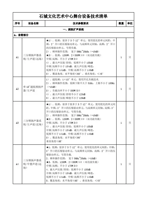
B5 二通道数字功率放大器/配接超低频声道★2)、功率:4欧姆不小于2500W,8欧姆不小于1300W,4欧姆桥接不小于5000W,8欧姆桥接不小于4800W;3)、很多于2端口的AESOP以太网/AES3接口,可自动切换至模拟备份信号;★4)、阻尼系数:>5000 @20-200 Hz;5)、总谐波失真+噪音:<0.3% 从 1W 到全功率;6)频率响应:20Hz-20KHz (+/-0.5dB)于 1W @ 8Ω;7)信噪比:> 106 dB/A (20-20K Hz A 加权) ;★8)DSP与以太网参数;模/数转换器:双24bit 96 kHz Tandem®结构,127 dBA的动态范围,9)、总谐波失真<0.005% (20 Hz - 20 kHz);数/模转换器:双24bit 96 kHz Tandem®结构,122 dBA的动态范围,10)、数字音频输入:AES3 (可选择自动切换至模拟备份音频);11)、可远程操纵开关机与监控工作状态;内置DSP处理模块;功率可升级;★12)、液晶操作面板,方便设置与储存、调用调节参数;外部尺寸:1 标准机架单位,★13)、提供产品国家强制3C认证证书复印件;2 台B6 二通道数字功率放大器/配接超低频声道1)、2通道数字功放;★2)、功率:4欧姆不小于2500W,8欧姆不小于1300W,4欧姆桥接不小于5000W,8欧姆桥接不小于4800W;3)、很多于2端口的AESOP以太网/AES3接口,可自动切换至模拟备份信号;★4)、阻尼系数:>5000 @20-200 Hz;5)、总谐波失真+噪音:<0.3% 从 1W 到全功率;6)频率响应:20Hz-20KHz (+/-0.5dB)于 1W @ 8Ω;7)信噪比:> 106 dB/A (20-20K Hz A 加权) ;★8)DSP与以太网参数;模/数转换器:双24bit 96 kHz Tandem®结构,127 dBA的动态范围,9)、总谐波失真<0.005% (20 Hz - 20 kHz);数/模转换器:双24bit 96 kHz Tandem®结构,122 dBA的动态范围,10)、数字音频输入:AES3 (可选择自动切换至模拟备份音频);11)、可远程操纵开关机与监控工作状态;内置DSP处理模块;功率可升级;★12)、液晶操作面板,方便设置与储存、调用调节参数;外部尺寸:1 标准机架单位,★13)、提供产品国家强制3C认证证书复印件;1 台。
AVC-X8500H INTEGRATED NETWORK AV AMPLIFIER 操作说明书附件9安装电池10遥控器的操作范围10特点11高音效11高性能14简易操作18部件名称与功能19前面板19显示屏23后面板25遥控器29连接方法扬声器安装34连接扬声器43连接扬声器之前43扬声器配置和“放大器分配”设置47连接5.1声道扬声器49连接7.1声道扬声器50连接9.1声道扬声器55连接13.1声道扬声器64连接15.1声道扬声器69双功放连接75连接11.1声道扬声器:第二对前置扬声器77连接多区域扬声器78连接电视机83连接1 : 配备了HDMI端子并兼容ARC(Audio Return Channel)/ eARC(Enhanced Audio Return Channel)的电视机84连接2 : 配备了HDMI端子且不兼容ARC(Audio Return Channel)/ eARC(Enhanced Audio Return Channel)的电视机86连接3 : 未配备HDMI端子的电视机87连接播放设备88连接机顶盒(卫星调谐器/有线电视)89连接DVD播放机或蓝光碟片播放机90连接兼容Denon Link HD功能的蓝光碟片播放机91连接摄像机或游戏机92连接电唱机93使用多声道输出端子连接设备94将USB存储设备连接至USB端口95连接至家庭网络(LAN)96有线LAN96无线局域网97连接外部控制设备98 REMOTE CONTROL插孔98 TRIGGER OUT 插口99连接电源线100播放基本操作102开启电源102选择输入源102调节音量103暂时关闭声音(静音)103播放DVD播放机/蓝光碟片播放机103播放USB存储设备104播放储存在USB存储设备上的文件105在蓝牙设备上收听音乐108从蓝牙设备播放音乐109与其他蓝牙设备配对111从蓝牙设备重新连接至本机112收听网络电台113收听网络电台114播放存储在计算机或NAS中的文件115播放存储在计算机或NAS中的文件116获取 HEOS App119 HEOS账户120从流媒体音乐服务播放121在多个房间聆听相同的音乐124 AirPlay功能128从iPhone、iPod touch或iPad播放歌曲129从iTunes播放歌曲129使用本机的遥控器进行iTunes的播放操作130在多个同步设备上播放iPhone、iPod touch或 iPad上的曲目 (AirPlay 2)131 QPlay功能132在本机上播放QQ音乐曲目132便捷功能133添加到HEOS最爱收藏134播放HEOS最爱收藏134删除HEOS最爱收藏135调节对话框和声乐的可听度(对话增强器)135调节各声道的音量以与输入源相符(声道电平调节)136调节音调(音调)137音频播放过程中播放所需视频(视频选择)138根据您的观看环境调节图片质量(画面模式)139在所有区域中播放相同的音乐(所有区域立体声)140选择声音模式141选择声音模式142直通播放143纯直通播放143自动环绕播放144声音模式类型介绍145可为每个输入信号选择的声音模式150 HDMI控制功能156设置步骤156智能菜单功能157睡眠定时器功能159使用睡眠定时器160快速选择附加功能161调用设置162更改设定163 ZONE2(区域2)/ ZONE3(区域3)(分开的房间)中播放164连接区域164 ZONE2 (区域2) / ZONE3 (区域3)播放169设置菜单图171菜单操作175音频176低音炮音量调节176低音同步176环绕参数177 Restorer184音频延迟185音量186 Audyssey®187图形 EQ190视频192画质调整192 HDMI设置194输出设置199模拟视频输出203屏幕显示203 4K信号格式204 TV格式206输入207输入分配207源重命名209隐藏源210输入源电平210输入选择211扬声器212 Audyssey®设置212扬声器的设定步骤(Audyssey®设置)214出错信息220检索Audyssey®设置设定222手动设置223放大器分配223扬声器配置233距离239电平240交叉241低音242前置扬声器243双声道回放243网络246信息246连接246 Wi-Fi设置247设置249网络控制251友好名称251诊断252 HEOS账户253您尚未登录253您已经登录253常规254语言254 ECO254区域2设置 / 区域3设置258区域重命名260快速选择名称260触发器输出1 / 触发器输出2261前显示屏261固件262信息265遥控ID266使用率数据267保存和读取267设置锁定268通过遥控器操作外部设备269注册预设代码270操作设备273操作学习功能276操作宏功能279指定使用遥控器的区域283设置远程ID284设置遥控器显示的显示时间长度284设置背景光285将遥控器的所有设置恢复为默认设置285提示提示287故障诊断289电源无法开启 / 电源关闭290使用遥控器无法执行操作291本机显示屏不显示内容291不发出声音292所需声音没有发出293声音中断或出现噪音296电视机上不显示视频297菜单屏幕不显示在电视机上299电视机上所显示菜单画面和操作内容的颜色与正常时不同299 AirPlay无法播放300USB存储设备无法播放301无法播放蓝牙设备302网络电台无法播放303计算机或NAS上的音乐文件无法播放304无法播放各种在线服务305 HDMI控制功能无效305无法连接至无线LAN网络306使用HDMI ZONE2时,设备无法正确运行307更新/升级错误消息308恢复出厂设置309恢复网络设置310保修和修理311附录关于HDMI312视频转换功能315播放USB存储设备317播放蓝牙设备318播放保存在计算机或NAS中的文件319播放网络收音机320个人记忆附加功能320最新功能记忆320声音模式和声道输出321声音模式和环绕参数323输入信号的类型和对应的声音模式326术语解释330商标信息340规格343索引348感谢您选购本款Denon产品。
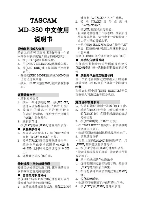
TASCAM MD-350中文使用说明书(控制)监视输入信息录音之前你可以监视(控制)和每一个输入终端相联结的输入信息的组成部分。
1、按[EJECT]键可推出光盘。
2、用[INPUT SELECTOR]选择输入源。
3、接[REC ORD]键(显示出“控制状态”)。
·既使把[REC MODE]键调成[MONO]输出的仍是双声道。
·插入一张MD或按[STOP]键取消控制状态。
调整录音电平·录制相同信号1、插入一张可录制的MD,按[REC ORD]键进入录音准备状态(“REC”灯亮)2、放节目的最高电平片断并转向[INPUT]控制键,以不致于使顶峰的“OVER”部分发亮。
3、重新放节目。
·按[PLAY]键或[READY]键就开始录音。
■录制数字信号1、在录音录音状态下,按[EDIT/NO]键直到“D-LEV 0.0DB”出现。
2、转动[TRACK]拨号盘调整录音电平,录音电平在变动范围是-6.0DB和+6.0DB之间时可选择设定在0.5DB上。
3、调整好之后按[YES]键。
录制过程中指定轨道号码特殊接点处指定轨道号码,使后来的再回放和编辑功能更简便快健。
■自动指定轨道号码把[AUTO TRACK FUNCTION]键打开可以在录音时自动指定轨道号码。
1、在录音或录音准备状态,按[EDIT/NO]键直到“A-TRACK>×××”出现。
2、转动[TRACK]拨号盘选择“A-TRACK>ON”。
3、按[YES]键完成设定功能。
·自动轨道功能牌工作状态时,在新轨道号码被提高前,信号电平一定保持在4或大于4秒的很低水平。
·一旦“AUTO TRACK FUNCTION”处于“ON”状态,既使在关掉电源之后这种状态也不会回复。
选择[A-TRACK>OFF]键回复之后按[YES] ■用手指定轨道号码在任意你想指定轨道号码的接点处按[RECORD]键,每一次按键都将提高轨道号码。
EAW KF740线性阵列音箱用于布雷登礼堂
佚名
【期刊名称】《演艺科技》
【年(卷),期】2015(0)8
【摘要】美国伊利诺伊州大学布雷登礼堂最近升级了扩声系统,采用了性价比极
高的EAWKF740线性阵列音箱。
系统采用一套左右构成的线性阵列——每侧8只KF740,加上由4只SB1001组成的中央音箱组以心形配置提供额外的低频表现。
阵列和低频音箱组悬挂得很高,保证观众视线不受阻碍。
主系统覆盖了管弦乐团和楼厅层坐席区域。
【总页数】1页(P73-73)
【关键词】音箱;线性;布雷;扩声系统;伊利诺伊州;管弦乐团;性价比
【正文语种】中文
【中图分类】J62
【相关文献】
1.OP4924L双12″线性阵列全频音箱 [J],
2.EAW推出JFL210型常曲率线性阵列 [J],
3.“先歌”推出EAW全新QX系列音箱 [J],
4.EAW Otto自适应超低频音箱 [J],
5.EAW阵列音箱助力常州金海岸演艺大舞台 [J],
因版权原因,仅展示原文概要,查看原文内容请购买。
SB LIVE!系列这是创新当年的高档产品,现在已经伦为中低端,但其品质还是不容置疑的.无论是玩游戏,看电影,听音乐还是录音,这块卡都能满足你的需要,喜欢在UC 里唱现场的朋友更是有非买不可的理由,因为这个卡能够实时的为你的歌声加上混响效果,这是其他公司的声卡所办不到的,LIVE!是一个庞大的系列,有超过20种不同型号的产品。
价格也非常便宜了,在100——300之间,所以我强烈推荐。
大体上分为以下几类:4.1声道的LIVE!,型号以CT开头,5.1的以SB开头,论坛上流行说的创新5.1就是指的SB LIVE!5.1,但是不要认为5.1就一定比4.1的好,看电影当然是5.1的好,但是录音恰恰相反,很多4.1的live!卡音质好于5.1系列,LIVE!卡越老的版本音质越好,新出的产品都是做了简化的。
A>LIVE!标准版-------主卡型号为CT4620,镀金接口,这是最早的SB LIVE!,用料最猛,所以音质是LIVE!系列里最好的,现在已经很难买到。
B>LIVE!白金版——主卡型号CT4760, 镀金接口,功能强大,有LIVE!DRIVER 扩展,音质次于标准版。
C>LIVE!超值版——型号包括CT4670,CT4780,CT4830,CT4831,CT4832等等其中CT4670音质最接近标准版,CT4780也不错,CT48XX的是数码版,是LIVE!系列中音质最差的版本。
D>LIVE!5.1——型号包括SB0060,SB0100,SB0220等等,支持5.1声道,杜比解码,功能较强,音质只强于数码版。
E>LIVE!OEM版——包括CT4790(SB PCI512),SB0200,其中CT4790是4.1声道也叫PCI512,是很罕见的版本,我也收藏了一片。
SB0200是最差的,严格的说这个不算是LIVE!卡,因为它采用了不同的芯片,也不能用公版驱动。
所以千万别买这种卡,其特点是一般的LIVE!是正方形芯片,这个版本是长方形。
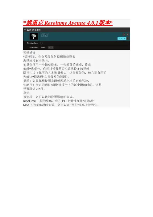
*挑重点Resolume Avenue 4.0.1版本*视频捕捉“源”标签,你会发现任何视频捕获设备您已连接到电脑上。
如果你使用一个捕获设备,一些额外的选项,将在剪辑“选项卡。
你可以设置是否应该从设备的视频隔行扫描(你不为大多数摄像头,这需要做的,但它是有用的为解决“锯齿形”与摄像头的问题)。
提示!如果你想使用来源或现场相机的自动驾驶,你能行!指定为通过剪辑“选项卡上的每个源的时间。
这是设置默认为5秒。
喜好首选项,您可以访问设置影响的方式,resolume工程的整体。
你在PC上通过打开“首选项”Mac上的菜单项叫大道,您可以在“视图”菜单上找到它。
一般偏好在这里,你还可以设置Resolume将使用的目录(文件夹)商店的录音,您是否记录视频和音频。
看到这是如何工作的细节记录后面的章节。
此外,您可以选择是否Resolume更新剪辑面板剪辑时被触发。
当你是你想将其关闭例如使用外部源触发片段序列(通过例如midi,OSC或DMX),而你申请的另一个影响夹在同一时间。
剪辑的开始偏移允许你让一个剪辑开始金额毫秒进一步剪辑的时间轴,以弥补延误与MIDI触发和/或长电缆。
Audio Preferences音频首音频“选项卡上列出的选项控制音频应该从Resolume输出:Audio Output Device音频输出设备Resolume应该使用音频输出设备。
如果ASIO设备被选中,将显示一个额外的按钮ASIO的设置,使访问。
Master Output Channels主输出通道应为主要输出渠道Resolume Preview Output Channels(resolume预览输出通道)音频监控,应使用的通道预览选定的剪辑或层。
您将需要一个音频设备支持超过2个通道,以便使用单独监控的预览。
Sample Rate采样率更高的采样率提供更高质量的音频,但需要更多的处理,特别是如果音频效果使用。
默认情况下通常会好起来的。
B5 二通道数字功率放大器/配接超低频声道★2)、功率:4欧姆不小于2500W,8欧姆不小于1300W,4欧姆桥接不小于5000W,8欧姆桥接不小于4800W;3)、不少于2端口的AESOP以太网/AES3接口,可自动切换至模拟备份信号;★4)、阻尼系数:>5000 20-200 Hz;5)、总谐波失真+噪音:<0.3% 从 1W 到全功率;6)频率响应:20Hz-20KHz (+/-0.5dB)于 1W 8Ω;7)信噪比:> 106 dB/A (20-20K Hz A 加权) ;★8)DSP和以太网参数;模/数转换器:双24bit 96 kHz Tandem®结构,127 dBA的动态围,9)、总谐波失真<0.005% (20 Hz - 20 kHz);数/模转换器:双24bit 96 kHz Tandem®结构,122 dBA的动态围,10)、数字音频输入:AES3 (可选择自动切换至模拟备份音频);11)、可远程控制开关机和监控工作状态;置DSP处理模块;功率可升级;★12)、液晶操作面板,方便设置和保存、调用调节参数;外部尺寸:1 标准机架单位,★13)、提供产品国家强制3C认证证书复印件;2 台B6 二通道数字功率放大器/配接超低频声道1)、2通道数字功放;★2)、功率:4欧姆不小于2500W,8欧姆不小于1300W,4欧姆桥接不小于5000W,8欧姆桥接不小于4800W;3)、不少于2端口的AESOP以太网/AES3接口,可自动切换至模拟备份信号;★4)、阻尼系数:>5000 20-200 Hz;5)、总谐波失真+噪音:<0.3% 从 1W 到全功率;6)频率响应:20Hz-20KHz (+/-0.5dB)于 1W 8Ω;7)信噪比:> 106 dB/A (20-20K Hz A 加权) ;★8)DSP和以太网参数;模/数转换器:双24bit 96 kHz Tandem®结构,127 dBA的动态围,9)、总谐波失真<0.005% (20 Hz - 20 kHz);数/模转换器:双24bit 96 kHz Tandem®结构,122 dBA的动态围,10)、数字音频输入:AES3 (可选择自动切换至模拟备份音频);11)、可远程控制开关机和监控工作状态;置DSP处理模块;功率可升级;★12)、液晶操作面板,方便设置和保存、调用调节参数;外部尺寸:1 标准机架单位,★13)、提供产品国家强制3C认证证书复印件;1 台。