博世——汽车毫米波雷达状态及趋势
- 格式:pdf
- 大小:353.23 KB
- 文档页数:4
双碳战略下我国汽车产业的变革及发展智能网联汽车注册咨询师考试一、判断题(每题4 分,共10 题,总分40 分)1、汽车产业与交通融合发展,智能汽车与智慧城市建设协同发展,将同时给智能交通、车联网等新兴产业和我国汽车产业带来空前的机遇。
A、对B、错A正确2、车辆控制一般分为纵向控制和横向控制。
纵向控制就是对方向盘的调节控制,横向控制就是对智能汽车的档位、油门和刹车的控制。
A、对B、错错误正确答案B3、随着车载传感器的智能化,传感数据也将飞速增加。
A、对B、错A正确4、双碳战略下我国汽车产业将产生重大变革,梯度性人才需求是这场变革胜出的关键。
A、对B、错A正确5、全球毫米波雷达市场竞争格局中,博世、大陆处于全球领跑地位。
A、对B、错A正确6、未来我国的燃油汽车只能是并跑,没有领跑的机会。
A、对B、错错误正确答案B7、目前,国际芯片厂商布局全自动驾驶超级计算平台,自动驾驶决策芯片完全被外资巨头垄断。
A、对B、错A正确8、机械式激光雷达将成趋势。
A、对B、错错误正确答案B9、单目摄像头仍然是当下和未来的主流。
A、对B、错A正确10、安全需求是汽车电子电气架构当中首要的需求。
A、对B、错A正确二、单选题(每题4 分,共10 题,总分40 分)11、DSP的厂商中,()的EyeQ图像处理芯片系列在2018年车载领域占比超70%,已经与全球27家汽车厂商达成合作。
A、TIB、MobileyeC、华为海思D、AmbarellaB正确12、预计2030年软件将占整车内容的()。
A、10%B、30%C、50%D、70%B正确13、目前,V2X通信系统以美国主导的()和中国主导的()为主。
A、DSRC标准,LTE-V2X标准B、DSRC标准,5G-V2X标准C、LTE-V2X标准,DSRC标准D、5G-V2X标准,DSRC标准错误正确答案A14、()是智能汽车的基础,是智能汽车的“眼睛”。
A、决策系统B、感知系统C、执行系统D、调度系统B正确15、2018年,全球CIS市场规模为155亿美元,2019年同比增长10%,达到170亿美元。
汽车域控制器的类型目录核心 (1)1 .动力域(安全) (1)2 .底盘域(车辆运动) (3)2.1.线控制动是未来汽车制动系统的发展趋势 (4)2.2.智能化的发展催促线控转向的产生 (5)2.3.EPS与SBW系统结构 (6)2.4.电助动力系统(EPS)主要供应商及客户 (6)2 .5.线控转向系统(SBw)主要供应商及产品现状 (7)3 .6.座舱域/智能信息域(娱乐信息) (7)4 .自动驾驶域(辅助驾驶) (9)5 .典型自动驾驶域控制器厂商及相应域控制器性能介绍 (10)6 .车身域(车身电子) (10)核心以博世经典的五域分类拆分整车为动力域(安全)、底盘域(车辆运动)、座舱域/智能信息域(娱乐信息)、自动驾驶域(辅助驾驶)和车身域(车身电子),这五大域控制模块较为完备的集成了13及以上级别自动驾驶车辆的所有控制功能。
1.动力域(安全)动力域控制器是一种智能化的动力总成管理单元,借助CAN/F1EXRAY实现变速器管理、引擎管理、电池监控、交流发电机调节。
其优势在于为多种动力系统单元(内燃机、电动机\发电机、电池、变速箱)计算和分配扭矩、通过预判驾驶策略实现CO2减排、通信网关等,主要用于动力总成的优化与控制,同时兼具电气智能故障诊断、智能节电、总线通信等功能。
未来主流的系统设计方案如下:1)以AUriX2G(387∕397)为核心的智能动力域控制器软硬件平台,对动力域内子控制器进行功能整合,集成ECU的基本功能,集成面向动力域协同优化的VCU,Inverter,TCU,BMS和DCDC等高级的域层次算法。
2)以ASI1-C安全等级为目标,具备SOTA,信息安全,通讯管理等功能。
3)支持的通讯类型包括CAN/CAN-FD,GigabitEthernet并对通讯提供SHA-256加密算法支持。
4)面向CPU∖GPU发展,需要支持AdapativeAutosar环境,主频需要提高到2G,支持1inux系统,目前支持POSIX标准接口的操作系统。

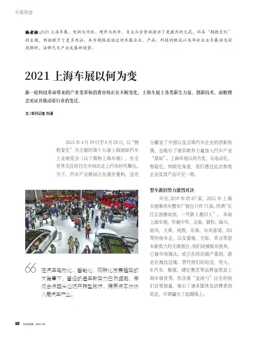
车展报道2021上海车展以何为变文 /本刊记者 刘通新一轮科技革命带来的产业变革和消费市场正在不断变化,上海车展上各类新生力量、创新技术、前瞻理念见证并推动着行业的变迁。
2021年4月19日至4月28日,以“拥抱变化”为主题的第十九届上海国际汽车工业展览会(以下简称上海车展),在全世界关注的目光中再次走上汽车时代舞台。
当下,汽车产业格局正在逐步重构,这充:编者按:2021上海车展,创新与传统、硬件与软件、自主与合资碰撞出了更激烈的火花,而其“拥抱变化”的主题,则被赋予了更多内涵。
本专题报道通过对参展企业、产品、科技的概述以及部分企业车展动态深度解析,诠释汽车产业发展新趋势。
分激发了中国以及全球汽车企业的创新热情,也吸引了诸多跨界力量加入汽车产业“战局”。
上海车展以何为变, 从电动化、智能化、网联化角度,我们透过此次参展企业及其产品可见一斑。
整车新旧势力激烈对决对比2019年的87家,2021年上海车展乘用车整车厂展台只有75家。
所谓“长江后浪推前浪,一代新人换旧人”。
本届上海车展,华晨中华、众泰、猎豹、海马、陆风、大乘、观致、东南、东风雷诺、DS 等传统车企,以及爱驰、天际、奇点等造车新势力均无缘展台。
他们或被股东放弃,已被市场淘汰;或正在经历破产重组,游走在淘汰边缘。
替代他们的坦克、恒大、R 汽车、极氪、捷尼赛思等品牌虽然是上海车展首秀,但含着“金汤勺”出生的他们自带流量,吸引了诸多媒体及消费者的驻足,可谓赢在了起跑线上。
在汽车电动化、智能化、网联化发展趋势的大背景下,曾经的造车新势力已然崛起,传统合资巨头也迈开转型脚步,跨界资本纷纷入局汽车产业。
车展报道虽然从参展整车企业数量上来看,2021上海车展规模有所缩水,但其“技术含量”却远远超过了往届。
以蔚来、小鹏为代表的第一代造车新势力已经站稳脚跟,并且持续用智能座舱、自动驾驶技术等领先科技巩固自己在纯电智能汽车领域的头部位置。
本届车展上,搭载蔚来最新驾驶技术NAD的蔚来ET7首发亮相。
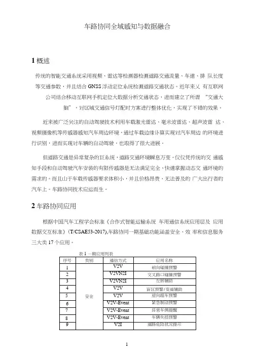
车路协同全域感知与数据融合1概述传统的智能交通系统采用视频、雷达等检测器检测道路交通流量、车速、排队长度等交通参数,并且结合GNSS浮动定位系统检测道路交通状态。
近年来乂有互联网公司结合移动互联网手机定位大数据分析交通状态,进而建立了所谓“交通大脑”,对区域交通信号灯配时方案进行整体优化,实现了不错的效果。
近来被广泛关注的自动驾驶技术利用车载激光雷达、毫米波雷达、超声波雷达、视频摄像机等传感器感知汽车周边环境,通过车载边缘讣算实现对汽车周边的环境进行识别,进而实现对车辆的自动驾驶,也取得了很大进展。
但道路交通是异常复杂的巨系统,道路交通环境瞬息万变。
仅仅凭传统的交通感知手段和自动驾驶汽车安装的有限传感器是无法满足完全、快速掌握动态交通环境的需求的。
而且山于车载传感器要求体积小,并且价格昂贵,无法普及的广大出行者的汽车上。
车路协同技术应运而生。
2车路协同应用根据中国汽车工程学会标准《合作式智能运输系统车用通信系统应用层及应用数据交互标准》(T/CSAE53-2017),车路协同一期基础功能涵盖安全、效率和信息服务三大类17个应用。
3车路协同感知体系3.1车路协同感知体系车路协同感知在结合现有的智能交通感知设备的基础上,增加了更加精密的路侧感知设备、车载感知设备和5G移动大数据。
路侧感知设备包括激光雷达、毫米波雷达和带LI标识别功能的视频摄像机:车载感知则是包括自动驾驶车辆能够感知到的数据,需要通过路侧单元RSU实时上传到边缘讣算节点。
图1车路协同感知体系3.2交通感知传感器32.1激光雷达激光雷达的测距精度非常高,基本上可以达到正负一两厘米,其至到了毫米级,分辨率也非常高。
机械激光雷达可以360度旋转,同时角分辨率也比别的雷达高。
但是LI前的机械旋转激光雳达的成本比较高,而且容易受到阳光雨雾和互干扰的影响。
它跟毫米波雷达一样是属于主动传感器。
U前的机械激光雷达也会受到工作温度以及工作环境震动的影响,它的工作温度一般是在零下10°到零上60°左右。
海外ADAS 执行层布局领先,国内厂商应用场景更加丰富通信行业1、本周推荐 通信(申万)板块估值目前已经跌到PE 32倍左右,行业估值层面已经逼近2013、2014年估值低点;中长期看中国5G 建设维持平稳,当前时间点我们认为市场对5G 投资悲观预期已经反映的较为充分。
由于2020年一季度受疫情因素影响上市公司业绩普遍偏低,看好子板块主设备商、光模块、电信运营商等一季度通信板块估值及业绩双升。
主设备商受益标的包括:紫光股份、中兴通讯、烽火通信、星网锐捷;光模块受益标的:中际旭创、光迅科技、天孚通信、新易盛; 电信运营商受益标的:中国移动、中国联通(港股)、中国电信;以及其他低估值标的:朗新科技、光环新网、金卡智能、航天信息等。
2、ADAS 专题:海外ADAS 执行层布局领先,国内厂商应用场景更加丰富目前ADAS 供应商主要以Tier1厂商为主,主要在感知层、决策层和执行层三大领域布局,海外厂商大多布局全面,国内厂商在执行层面仍有待突破;但其在应用场景和V2X 方面布局更加深入,包括无人清扫、无人农机、无人接驳、RoboTaxi 、无人送货、无人大巴、自动驾驶卡车、AVP 等,而海外集中在高速公路、城市道路、自主泊车三大场景。
我们认为,随着高级别自动驾驶的推广以及政策电子架构的集中域控制的转变,汽车电子基础架构对芯片算力、通信能力及软件复杂程度要求不断提升,ADAS 系统中决策层和执行层的重要性不断提高。
目前海外厂商依靠传统行业优势在执行层占据优势地位,国内厂商接下来的在执行层的相关收并购和业务布局值得关注;同时集中域控制器和复杂的电子电气结构也为产业合作模式和供应商带来重新洗牌,行业相关整车厂合作和软硬件分离的新势力与代工的战略合作值得关注,比如沃尔沃与Veoneer 、现代与安波福、华为与长安汽车、德赛西威与小鹏汽车等合作。
2021年02月07日此外,国内更多应用场景和V2X、车路协同领域布局也为相关硬件厂商带来一定市场机遇,包括高精度地图、惯导、激光雷达、毫米波雷达和车联网相关模块等。
商用车底盘线控技术研究现状及应用进展摘要:线控底盘技术是国内主机厂和零部件厂商在突破“卡脖子”瓶颈,掌握汽车核心技术和提升产品竞争力的重要关键之一。
同时线控底盘是实现新能源智能汽车、自动驾驶SAEL3的“执行”基石和重要技术基础。
在线控底盘四大技术系统中,线控油门和线控换挡技术发展较为成熟,技术门槛相对较低,且渗透率稳定。
线控制动技术成熟度提升较快,且由于线控制动技术解决了新能源汽车真空助力缺失的问题,在新能源汽车中渗透率将快速提升。
关键词:商用车;底盘线控技术;应用引言当今全球汽车产业面临前所未有的百年变局,在国家“双碳”目标指引下,中国汽车产业正在向着电动化、智能化和网联化(简称“三化”)快速发展,辅助驾驶和自动驾驶技术大量涌现。
线控底盘技术作为支撑实现辅助驾驶和自动驾驶的关键基础技术,也是被行业公认的“卡脖子”技术,亟需突破解决。
因此,线控底盘技术已成为商用车行业技术的研发热点。
1线控底盘的工作原理线控底盘包含了线控转向系统、线控制动系统、线控驱动系统、线控悬架系统等,各个系统与车辆VCU的信息传输与控制由CAN总线完成,当摄像头、毫米波雷达、激光雷达、超声波雷达等环境传感器采集到环境信息后,通过运算平台的计算,将车辆的控制信息通过CAN总线传输至车辆的整车控制器,整车控制器对控制信息再次分析处理,并通过CAN总线发送至线控底盘的各个模块,从而根据实际道路环境实现转向、制动、加速、换挡等动作。
2线控底盘技术框架和发展方向概述新能源汽车变革是中国汽车产业链弯道超车的历史性机遇。
传统燃油车时代欧美日整车厂占据主导地位,涌现出博世、采埃孚、麦格纳、大陆等零部件巨头;而在新能源汽车时代,中国品牌有望实现弯道超车,带动产业链协同成长,叠加中国速度和性价比优势,必将诞生领先全球的自主零部件巨头。
新能源智能汽车需求驱动底盘线控化升级,传统燃油车的底盘系统由驱动、传动、转向、制动等组成,机械、液压零部件繁多,且结构复杂,无法满足新能源和自动驾驶对车辆操控性和主动安全的需求;而通过线束传输信号+电机直接驱动能实现对执行机构高效、精准的控制,底盘控制系统的智能化升级驱动线控转向、线控制动等线控系统的技术发展和应用。
[Table_ReportType] [Table_StockAndRank][Table_Author]138****0611********************91100031[Table_Title]理想L9上市,具备爆款潜质,关注产业链机遇[Table_ReportDate] 2022年06月23日[Table_Summary][Table_Summary]➢2022年6月21日,理想汽车发布第二款车型,全尺寸家庭智能旗舰增程式电动SUV ——L9(X01)。
L9售价45.98万元,长宽高5,218 x 1,998 x 1,800 mm,轴距3,105 mm。
L9 Max在智能座舱、智能驾驶、动力系统、内外饰方面均有突出表现。
我们预计,L9 Max作为引领行业“第三智能空间”打造的现象级产品,有望接棒理想ONE,成为月销过万的爆款车型,助力理想在新能源高端市场实现份额突破。
➢理想L9有什么亮点?➢智能座舱:重磅打造“移动游戏&影音空间”。
1)车载屏幕:除中控屏、副驾娱乐屏之外,还配备了后舱可折叠娱乐屏,三屏皆采用15.7 英寸3K高清分辨率OLED屏幕,可互相投屏,支持触控、语音(基于6颗麦克风)、手势交互(基于3DToF传感器)。
2)车载声学:搭配21个扬声器+7.3.4全景声音响,采用杜比全景声技术和4D沉浸式影音系统,功放最大功率达到2160W,着力打造影院级别的影音体验。
3)车载仪表:L9取消了仪表板,用超大尺寸彩色AR-HUD+位于方向盘上部的触控驾驶交互屏替代仪表,提供导航、车速、动力模式等车辆行驶的各项信息。
4)算力平台:标配2颗高通骁龙8155芯片,24G内存和256G储存芯片。
➢智能驾驶:L9搭载理想全栈自研的AD Max智能驾驶系统。
算力方面,2颗英伟达Orin-X处理器提供508TOPS的总算力,支持自动泊车、城市智能驾驶、远程召唤、OTA升级等场景和功能。
自动驾驶芯片:GPU的现在和ASIC的未来——自动驾驶系列报告三:车载芯片篇行业观点⏹自动驾驶系列报告第三篇,我们将按时间顺序梳理车载芯片的发展历程,探讨未来发展方向。
汽车电子发展初期以分布式ECU架构为主流,芯片与传感器一一对应,随着汽车电子化程度提升,传感器增多、线路复杂度增大,中心化架构DCU、MDC逐步成为了发展趋势;随着汽车辅助驾驶功能渗透率越来越高,传统CPU算力不足,难以满足处理视频、图片等非结构化数据的需求,而GPU同时处理大量简单计算任务的特性在自动驾驶领域取代CPU成为了主流方案;从ADAS向自动驾驶进化的过程中,激光雷达点云数据以及大量传感器加入到系统中,需要接受、分析、处理的信号大量且复杂,定制化的ASIC芯片可在相对低水平的能耗下,将车载信息的数据处理速度提升更快,并且性能、能耗和大规模量产成本均显著优于GPU和FPGA,随着自动驾驶的定制化需求提升,ASIC专用芯片将成为主流。
⏹目前出货量最大的驾驶辅助芯片厂商Mobileye、Nvidia形成“双雄争霸”局面,Xilinx则在FPGA的路线上进军,Google、地平线、寒武纪在向专用领域AI芯片发力,国内四维图新、全志科技等也在自动驾驶芯片领域积极布局。
Mobiley e的核心优势是EyeQ 系列芯片,可以处理摄像头、雷达等多种传感器融合产生的大量数据,在L1-L3自动驾驶领域具有极大的话语权,目前出货量超过了2700万颗;NVIDIA在GPU领域具有绝对的领导地位,芯片算力强大且具备很强的灵活性,但功耗高、成本高,AI机器学习并不太适合GPU的应用;此外Google、地平线、寒武纪、四维图新等更聚焦在针对不同场景下的具体应用,芯片设计也开始增加硬件的深度学习设计,自动驾驶上AI的应用已经成为未来的趋势。
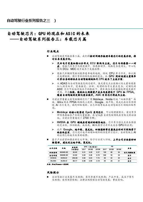
⏹基于产业前景和潜在的巨大市场,给予行业买入评级,上市公司方面看好四维图新,建议关注地平线、寒武纪。
公司名称代码收盘价(元/美元)EPS (元/美元)PE业务来源:Wind/Thomson一致预测风险提示⏹自动驾驶行业发展不及预期;装车渗透不及预期;产品开发、成本下降不及预期;使用场景限制;法律法规限制自动驾驶发展;事故影响。

2022年10月17日行业研究高级自动驾驶必备传感器——激光雷达行业跟踪报告系列之一电子行业买入(维持)分析师:刘凯执业证书编号:S0930517100002分析师:石崎良执业证书编号:S0930518070005分析师:何昊执业证书编号:S0930522090002300资料来源:Wind相关研报Pico4发布会召开,内容生态全面发力——VR/AR行业跟踪报告之三(2022-09-30)Pico Neo4和小鹏G9重磅发布,关注XR与汽车智能化投资机会——光大证券通信电子行业周观点第40期(20220924)(2022-09-26)Pico即将发布新机Pico 4,SiFive推出车用RISC-V内核系列——光大证券通信电子行业周观点第39期(20220918)(2022-09-18)激光雷达:高级自动驾驶必备传感器。
激光雷达是高级自动驾驶的核心传感器,主要利用光波获取并处理信息,起到测距、避障、定位和导航等对驾驶的辅助作用。
它的基本原理是通过发射器向目标发射探测信号(激光束)和传感器接受目标反射回来的信号来测量与目标之间的距离、分析目标反射回来的信息得到目标的距离和物理属性等信息,用于避障,于此同时结合地图,便于实现定位以及导航功能。
图表1:激光雷达基本原理图资料来源:SlidePlayer,光大证券研究所以此方法,激光雷达收集的数据是离散的,被叫做点云数据,点云数据描述了目标物体的物理属性和位置,包括三维坐标X,Y,Z、颜色值和强度值等,通过处理点云数据来获得目标的信息。
图表2:激光雷达点云图资料来源:禾赛科技,光大证券研究所激光雷达发展历程:从科研到智能驾驶核心部件。
激光雷达诞生于1960-1970年代,最初用于科研与测绘领域;2000年以前逐渐走向商业化,出现了单线扫描式2D激光雷达产品;2000-2015年进入车辆应用的初期,高线数激光雷达开始应用于无人驾驶的避障与导航,以国外厂商为主;2015-2019年无人驾驶和高级辅助驾驶领域蓬勃发展,成为技术热点,国内厂商开始跟进研究并陆续取得突破;2019年至今,随着智能驾驶的迅速发展,作为感知层重要的一部分,激光雷达也加快了发展的脚步,技术更迭层出不穷,产品性能持续优化,激光雷达向着芯片化和阵列化发展。
驾驶台盲距计算公式随着科技的不断发展以及相关政策的不断推出,自动驾驶汽车得到了快速的发展及强有力的保障。
但是自动驾驶汽车的发展始终离不开一个重要的目标,那就是保障自身的安全。
为了确保自动驾驶汽车的安全,即意味着自动驾驶汽车在行驶过程中不会撞到任何人或物,所以在汽车行驶过程中需要知道其周边物体和车辆本身之间的距离。
为了实现这一目标,需要提前测量车辆前方障碍物与车辆之间的距离,从而保证自动驾驶汽车的安全性。
实现自动驾驶汽车距离估计的方法有多种,它们必须遵循以下原则:①该方法具有准确性和稳定性;②基于不同的硬件和软件解决方案;③使用不同工作原理的传感器;④在做研究时,先验假设要尽可能的少。
自动驾驶汽车实现距离估计的主要方法是使用传感器(如摄像头、雷达等)对车辆周边物体进行距离检测,从而实现距离估计的目的。
其方法有如下几种:1.基于毫米波雷达的距离估计毫米波雷达在技术上已经非常成熟,最早开始应用于自适应巡航领域。
在英飞凌推出24GHZ单片雷达方案之后,毫米波雷达被应用到了ADAS的各个模块中,在全球范围内,毫米波雷达的出货量达到了千万级。
在自动驾驶汽车的距离估计中都使用了毫米波雷达作为传感器,来进行周边障碍物的识别和测距等工作。
如今,全球市场范围内的毫米波雷达份额主要被国外第一梯队的供应商垄断,如博世、大陆等,而随着国内市场的发展,像国内的华域汽车这样的供应商也都在布局发力毫米波雷达。
据数据显示,2018年国内毫米波雷达的市场规模约为70亿,比2017年增长了一倍,而到今年2020年预计约为240亿,到2025年预计约为320亿。
毫米波雷达,即工作在毫米波波段探测的雷达,其实质是电磁波,波长约为1-10mm,毫米波雷达通过将毫米波发射出去,然后接受回波,根据发射和接收的时间差来测得前方障碍物的位置和距离。
基于毫米波雷达的距离估计方法,主要以FMCW调制方法来进行测量距离,其原理图如下所示:其原理是通过振荡器来形成连续变化的信号,对于发出的信号和接收的信号,它们之间会形成频率差,而该频率差值与毫米波的发射时间和接收时间的差值之间呈线性相关,只需要测量频率差,就可以实现车辆与前方物体距离的测量估计。
adas法规ADAS是Advanced Driver Assistance System的简称,翻译成中文的意思就是高级驾驶辅助系统,简单来讲就是紧急情况下在驾驶员主观反应之前作出主动判断和预防措施,来达到预防和辅助的作用。
我们可以称它为自动驾驶的简化版——ADAS高级辅助驾驶系统。
ADAS确切来说并不是自动驾驶,可以说这两者的研究重点完全不同。
ADAS是辅助驾驶,核心是环境感知,而自动驾驶则是人工智能,体系有很大差别。
不过ADAS也可以视作自动驾驶汽车的前提,判断一个系统是ADAS系统还是自动驾驶系统,关键看该系统是否有决策部分。
ADAS采用的传感器主要有摄像头、雷达、激光和超声波等,可以探测光、热、压力或其它用于监测汽车状态的变量,通常位于车辆的前后保险杠、侧视镜、驾驶杆内部或者挡风玻璃上。
早期的ADAS技术主要以被动式报警为主,当车辆检测到潜在危险时,会发出警报提醒驾车者注意异常的车辆或道路情况。
近年来ADAS市场增长迅速,原来这类系统局限于高端市场,而现在正在进入中端市场,与此同时,许多低技术应用在入门级乘用车领域更加常见,经过改进的新型传感器技术也在为系统布署创造新的机会与策略。
驾驶辅助系统主要由GPS和CCD相机探测模块、通信模块和控制模块等组成。
其中,GPS和CCD相机探测模块通过GPS接收机接收GPS 卫星信号,求出该车的经纬度坐标、速度、时间等信息,利用安装在汽车前部和后部的CCD相机,实时观察道路两旁的状况;通信模块可以发送检测到的相关信息并在相互靠近的汽车之间实时地传输行驶信息;控制模块可以在即将出现事故的时候做出主动控制,从而避免事故的发生。
ADAS通常包括以下系统:1、导航系统;2、实时交通系统TMC(Traffic Message Channel);3、电子警察系统ISA(Intelligent Speed Adaptation或Intelligent Speed Advice);4、车联网系统VSA(Vehicular Communication Systems);5、车辆检测VD(Vihicle Detection):在仅基于视觉的模式下,VD目前要能检测70米远的车辆,并能持续跟踪到100米开外。
2021款比亚迪唐DM-i◆文/深圳李明权汽车维修技能大师工作室 蒋烈溪 李明权故障现象一辆2021款比亚迪唐D M-i混合动力汽车,搭载B Y D476Z Q C型1.5T发动机,行驶里程为31533k m,VIN码为LCOC74C48M111****。
车主反映该车启动后仪表台上提示“车道偏离功能受限”(图1),行车过程中无法使用车道保持功能。
图1 故障车仪表台上的故障提示故障诊断与排除接车时了解到,该车由于发生交通事故,车辆前部受损,在外面修理店更换了前保险杠、中冷器、水箱护罩、前毫米波雷达等。
装复后发现无法对新更换的前毫米波雷达(副厂件)进行编程及标定。
期间去过其他几家修理店进行检修,但均未能排除故障。
后来经人介绍,将故障车开到我店进行检修。
接车后,使用比亚迪原厂诊断电脑VDS2100对全车进行诊断扫描,发现前毫米波雷达系统存有历史故障码U014086-BCM数据故障(图2),可以正常删除该故障码,但是删除后再次启动时,故障码会再次出现。
导致该故障的可能原因有:系统软件故障;前毫米波雷达自身故障;多功能视频控制器故障;相关线路故障等。
车辆在事故维修中,前保险杠线束有部分受损,修理厂已经重新修复。
前毫米波雷达由于碰撞损坏,更换了新的雷达。
按照作业要求,更换新的前毫米波雷达后需要重新对系统进行配置写入及标定操作。
修理厂使用某品牌的通用诊断仪多次进行配置及标定,均未能排除故障。
通过比亚迪TIS系统查询该车的车型配置,使用VDS2100进入前毫米波雷达系统,写入正确的车型配置,然后进入前毫米波雷达系统,进行路面动态标定程序。
上路标定大概15min后,VDS显示校准进度为100%(图3),说明已经标定成功。
标定完成后,故障车可以正常使用定速巡航功能,但是车道偏离功能依然无法使用。
重新检查受损的前保险杠线束,发现连接前毫米波雷达的线束有多处线束被挤压破损后又重新修复的痕迹。
查阅故障车型毫米波雷达电路图(图4)得知,前毫米波雷达插头有6根线,共有图2 故障车内存储的历史故障码图3 前毫米波雷达标定界面Copyright©博看网. All Rights Reserved.372023/06·汽车维修与保养38-CHINA ·June栏目编辑:桂江一 ********************维修实例2组网络,其中2、3号脚连接底盘网。
Automotive Radar – Status and TrendsMartin SchneiderRobert Bosch GmbH, Corporate Research, PO box 77 77 77, D-31132 Hildesheim, Germany, +49 5121 49 2543,Schneider.Martin@Abstract — The paper gives a brief overview of automo-tive radar. The status of the frequency regulation for short and long range radar is summarized because of its impor-tance for car manufacturers and their sensor suppliers. Front end concepts and antenna techniques of 24 GHz and 77 GHz sensors are briefly described. Their impact on the sensor’s field of v iew and on the angular measurement capability is discussed. Esp. digital beamforming concepts are considered and promising results are presented.I. I NTRODUCTIONFirst experiments in the field of automotive radar took place already in the late 50’s. I n the 70’s, more or less intensive radar developments started at microwave fre-quencies. The activities of the last decades were concen-trated mainly on developments at 17 GHz, 24 GHz, 35 GHz, 49 GHz, 60 GHz, and 77 GHz. Even from the early beginning in automotive radar the key driver of all these investigations has been the idea of collision avoidance; this idea has spent enormous motivation for many engi-neers all over the world to develop smart vehicular radar units. During this quite long period a lot of know-how has been gained in the field of microwaves and in radar signal processing. Accompanied by the remarkable pro-gress in semiconductor microwave sources (esp. Gunn sources and GaAs MMI Cs) and in available computing power of microcontrollers and digital signal processing units, the commercialization of automotive radar became feasible in the 90’s.Competing and complementing technologies in vehicu-lar surround sensing and surveillance are Lidar, ultrason-ics, and video cameras (based on CCD or CMOS chips including near-infrared sensitivity). Car manufacturers and suppliers are developing optimized sensor configura-tions for comfort and safety functions wrt. functionality, robustness, reliability, dependence on adverse weather conditions etc. Last but not least the total system costs have to meet the marketing targets to be attractive for the end customers. First applications with surround sensing technologies were parking aid (based on ultrasonics), collision warning, and Adaptive Cruise Control (ACC). For instance, collision warning systems were successfully introduced in the US in the 90’s. Greyhound installed more than 1600 radar systems (24 GHz) in their bus lines yielding a reduction of accidents of 21 percent in 1993 compared to the year before.ACC was commercialized for the first time in Japan in 1995. Whereas Lidar-ACC has been favored esp. in Ja-pan, European and US companies have been focused mainly on radar based ACC. I n 1999, Mercedes intro-duced the 77 GHz “Distronic” into the S class, followed by other premium models equipped optionally with an ACC, such as BMW 7 series, Jaguar (XKR, XK6), Cadil-lac (STS, XLR), Audi A8, and VW Phaeton. ACC is also available in Mercedes E, CL, CLK, SL class, BMW 5 and 6 series, Audi A6, Nissan (Cima, Primera), Toyota (Harrier, Celsior), Lexus (LS, GS), and Honda (Accord, nspire, Odyssey). Furthermore, ACC will become an option in the new BMW 3 series and in the new VW Passat, both with start of production in 2005.Whereas European car manufacturers offer 77 GHz systems only for ACC systems so far, their Japanese competitors Honda and Toyota already introduced an active brake assist for collision mitigation (additionally to ACC) in 2003 based on 77 GHz long range radar (LRR) technology. I n contrast to the only smooth deceleration capability of an ACC system (because ACC is only mar-keted as a comfort feature), the active brake assist pro-vides much higher braking forces for deceleration, when a threatening situation is identified and the driver starts braking, but maybe not as strong as it would be necessary to avoid a crash.This shows the trend from “comfort only” functions to active safety systems with radar sensing technologies that serve both the comfort and the safety domain. Within the next few years these active safety systems will be intro-duced in Europe. Mercedes started with the first genera-tion of their Presafe system in the S class in 2003, which isn’t based on surround sensing techniques yet but (only) on the data of the electronic stability program (ESP) and the antilock braking system (ABS). If these control units identify an imminent accident due to the car’s dynamics, electronic seat belt tensioners will be activated, seat ori-entations will be adapted, and the sunroof will be closed. The next step in this evolutionary process will be to gain some more milliseconds in advance for reaction and for automatic activation of suitable protection measures. Bosch names this system “Predictive Safety System (PSS)”, which will have mainly three stages. The first one (PSS1, to be introduced in 2005) is a preset of the brake system. As soon as a threat will be identified by the 77 GHz LRR, the brake system will be pre-filled, but this won’t be noticed by the driver. But when the driver pushes the brake pedal in such a situation, maximum braking forces will be available without any latency. I n the second stage (PSS2, 2006) the driver will be notified in a hazardous situation with an automatic, very short but intensive brake activation, accompanied by optical or acoustic signals. I n the third stage (PSS3) an automatic emergency brake will be initiated if otherwise a crash couldn’t be avoided. Bosch was recently awarded for its PSS with the “Gelber Engel (Yellow Angel)” from theGerman auto club ADAC (similar to AAA in the US) in the category “Innovation”.Short range radar (SRR) sensors for passenger cars will be mounted first in premium class models for pre-crash sensing, ACC support, parking assistance, and blind spot surveillance. Preferred microwave technology is 24 GHz in ultra wideband (UWB) operation with high range resolution in the range of cm.II. F REQUENCY R EGULATIONA lot of progress has been made during the last years in the frequency regulation for automotive radar. The 76 – 77 GHz band was regulated already in the 90’s fol-lowed by a standardization in Europe (ETSI EN 301 091). Now, this band is allocated for Intelligent Transport Services (ITS) in Europe, North America, and Japan.For short range applications UWB sensors are widely preferred because of their low cost perspectives and their high resolution in the range cm. The Federal Communi-cations Commission (FCC) regulated UWB for the North American market (NAFTA) already in 2002. For auto-motive UWB short range radar systems the FCC allo-cated the band 22 – 29 GHz with a maximum mean power density of -41.3 dBm/MHz.In 2002, more than 30 mainly European car manufac-turers and suppliers founded the Short range Automotive Radar frequency Allocation consortium (SARA). SARA’s main objective is to support UWB regulation for automotive radar in the 24 GHz range in Europe. Be-cause of strong objections of the telecom industry and earth observation institutions, a lot of effort was dedi-cated to find a compromise and to enable automotive UWB radar systems. On 17 January 2005 the commis-sion of the European Community finally decided to allo-cate the range of 21.65 – 26.65 GHz for UWB short range radar. The marketing of these systems is allowed from 07/2005 till 06/2013. The penetration rate is re-stricted to 7 percent of all cars in each country of the European Community. It is expected that this time frame of eight years will be sufficient to develop inexpensive short range radar sensors operating at a new frequency without impairing other commercial, scientific or military systems and services. Hence, in March 2004 the Euro-pean commission allocated the frequency range 77 – 81 GHz for UWB SRR with permitted usage from 2005 onwards. Anticipating the allocation of this band also in Japan and North America, the SRR suppliers will proba-bly shift their UWB developments from 24 GHz to 79 GHz in the medium term.III. F RONT E ND T ECHNIQUES AND A NTENNA C ONCEPTS Functional requirements, limited space for the sensors’ mounting, regulatory issues, components’ and fabrication costs, and marketing schedules mainly determine the choice of sensor concepts. One main requirement for long range radar is a range capability up to 150 .. 200m. With regard to the radar equation of a monostatic radarwe have in mind that the maximum range R max is propor-tional to the square root of the effective antenna aperture size A and to the square root of the frequency. V denotes the reflectivity of the target, P Tx the transmitted power and P min the minimum power necessary for detection. Therefore, highest frequencies should be preferred to get small box volumes. But this demand is contrary to the availability of cost saving microwave technologies. The antenna size of 77 GHz LRR sensors may decrease to approx. 50 x 50 mm 2. But even when the sensitivity would be sufficient, high antenna directivity and low sidelobes would still be necessary to cope with the effects of guard rails and irrelevant surroundings besides the road lanes.A. 24 GHz SensorsSRR sensors do not require long range capability. Hence, lower frequencies are preferred, enabling the use of available microwave components also used in the telecom industry. The 24 GHz technology seems to be the best compromise between today’s component costs and sensor size. Typically, SRR sensors do not measure the angle of detected objects and they have a very broad lateral coverage. Therefore, single antenna elements are sufficient. Only vertically the beams are directed to in-crease antenna gain and to minimize clutter effects from the road surface [1]. SRR sensors are typically operated in pulsed mode (pulse, pulse Doppler) or in continuous wave mode (CW, FMCW, FSK, FMCW & FSK). Also coded radar with spread spectrum techniques (pulsed, CW, pseudo-noise) is a common technique. For instance, Delphi’s 17 GHz radar is a phase coded CW radar with a pseudo-noise (PN) BPSK modulation. The M/A-Com sensor is a pulsed radar. Hella is developing a 24 GHz UWB radar for short range applications and a narrow-band FMCW radar operating in the license free 24 GHz ISM band with a maximum range of 70m [2].To measure not only targets’ distances but also their angular positions, several adjacent sensors can be used. Their measurements of the targets’ distances are fused in a trilateration algorithm yielding also the angular posi-tions. Valeo-Raytheon is developing a multibeam phased array SRR that provides angular information itself. B. 77 GHz SensorsMain manufacturers of 77 GHz LRR sensors are ADC (subsidiary of Continental Temic in cooperation with M/A-Com), Bosch, Delphi, Denso, TRW (Autocruise), Fujitsu Ten, and Hitachi. Fig. 1 shows Bosch’s LRR in its 2nd generation, production has been started in 2004. The system has a box size of only 74 x 70 x 58 mm 3 (H x W x D) and contains all sensing and ACC functionality. The 77 GHz circuitry contains 4 feeding elements (poly-rods) directly attached to 4 patch elements on the RF board, illuminating a dielectric lens. The monostatic analog beamforming approach results in a broad illumi-nating transmit beam and four single receiving beams which partially overlap in azimuth yielding a total azi-muthal coverage of ±8 degrees, see Fig. 2. The modula-tion is FMCW with a triangular shape [3].,442min 2maxO S VP A P R Tx (1)Fig. 1. Bosch ACC, 2nd generationFig 2. Receive beam pattern of Bosch ACC, 2nd generationTRW also uses the dielectric lens concept whereasADC (resp. M/A-Com) takes advantage of a folded struc-ture with a very low profile resulting in a sensor depth of5cm. Other companies (Delphi, Fujitsu Ten, Mitsubishielectric, Celsius Tech) use mechanical mechanisms tosteer the beam in azimuth. Although mechanical radarscanners yield quite good detection performance, theymight be sensitive in their mechanical reliability overlifetime. Moreover, they are limited concerning furtherminiaturization. Delphi’s and Fujitsu Ten’s mechanicalradar are in series production.IV. D IGITAL B EAMFORMIMG C ONCEPTS77 GHz radar sensors with digital beamforming (DBF)front ends were introduced into the market by Japanesecompanies in 2003. Denso built a bistatic LRR with pla-nar patch antennas with a range capability up to 150mand a field of view of approx. ±10 degrees [4]. The ninereceiving antennas are multiplexed with four 77 GHzSP3T switches to only one base band channel, see Fig. 3.Fig. 3. Denso’s 77 GHz DBF sensor [4]The Toyota CRDL 77GHz LRR radar (Fig. 4, [5])switches 3 equal transmitting antennas and 3 receivingantennas resulting also in one base band channel, and,after demultiplexing in the digital domain, nine digitalreceiver channels for DBF.Fig. 4. Toyota CRDL Radar with DBF, 77 GHz, [5]A. Direction of Arrival EstimationAll conventional direction of arrival (DOA) estimationmethods as monopulse techniques (comparison of thereceived signals in partially overlapping beams) or spatialpower spectrum measurement techniques (mechanicalscanning, phased array) do have an angular resolution inthe range of the half-power beamwidth. Hence, the angu-lar resolution directly depends on the aperture size, be-cause the 3 dB beamwidth of an antenna with diameter Dand constant illumination is approx.Therefore, the angular resolution of long range 77 GHzsensors is typically in the range of 2 .. 5 degrees. Toovercome this limitation, parameter estimation methodsbased on subspace techniques can be applied. Thesemethods rely on a subspace decomposition of the noisyreceived signals of an array of multiple antenna elements.With an eigenvalue decomposition of the autocorrelationmatrix of the received signals of a uniform linear array(ULA) the noise and the signal subspace can be deter-mined. Knowing these subspaces, the DOA’s of the tar-gets can be estimated. Well known in array signal proc-essing theory are the Music and Esprit algorithms [6, 7].We applied these techniques to a 24 GHz SRR with digi-tal beamforming and published very promising results in2002 [8].In our further work we started to transfer this approachto the 77 GHz domain. The main objectives of our cur-rent research activities are to gain know-how about 77GHz DBF concepts and their benefits in combinationwith parameter estimation techniques and to investigatetheir impact on development efforts. Fig. 5 shows one ofour 77 GHz DBF front ends with a ULA consisting ofeight parallel receiving columns. The transmit antennaconsists out of 4 columns with a tapered power distribu-tion yielding a low sidelobe level of approx. -27 dB. The3 dB beamwidth of the transmit antenna is approx. 26degrees and the antenna gain is 20.5 dB..593DdBOT q|(2)Another front end with extended arrays for long range operation was put into a water-resistant housing and was mounted on our test vehicle, see Fig 6. First results of our implementation of parameter estimation techniques on a 77 GHz DBF demonstrator are shown in Fig. 7. Themarkings no. 1 and 2 indicate the estimation of the Esprit algorithm. Although the half power beamwidth of the virtual beams of the DBF sensor is approx. 8.5 degrees, both cars with their angular separation of less than 4 degrees are detected and no ghost target between both objects does appear.Fig. 6. Test vehicle with 77 GHz DBF demonstrator (also insert in right bottom corner)Fig. 7. Angular measurement of two cars at the same dis-tance (60 m radial distance and 4 m lateral separation)V.C ONCLUSIONShort range radar in ultra wideband operation at 24 GHz and at 79 GHz from 2013 at the latest will be used first in premium and later on in upper class models. Main applications will be ACC support, pre-crash detection, parking assistance, and blind spot surveillance. Market introduction of 24 GHz SRR will start in 2005. SRR sensors won’t have angular measurement capabilities in the first generation (except the Valeo-Raytheon sensor), but future generations will also be able to provide angu-lar information. Although these sensors will be more expensive, they will contribute to the minimization of the total number of sensors and therefore they will reduce overall system costs.77 GHz ACC systems will be extended to be opera-tional at low speeds including full stop capability. This will provide increased customer benefits and it will con-tribute significantly to the market success of ACC sys-tems. In the same manner the 77 GHz sensor will be used not only for comfortable driving (ACC stop & go) but also for predictive and active safety systems. Active safety systems up to an automatic emergency braking in unavoidable crash situations will be the key for a consid-erable reduction of the total number of crashes and fatali-ties.The detection performance of 77 GHz sensors will be further improved, for instance wrt. false alarm rate and reaction time. Also sensor costs will be lowered. Planar antennas in combination with digital beamforming pro-vide interesting front end concepts for 77 GHz radar. These techniques might become feasible for high volume production as far as costs of 77 GHz components and powerful digital signal processing units will further de-crease.R EFERENCES[1] I. Gresham, A. Jenkins, “Ultra-wideband radar: Regula-tions, Applications, and Challenges,” Int. Microwave Sym-posium 2003, Philadelphia, Penn., June 2003[2] Th. Wixforth, W. Ritschel, “Multimode-Radar-Technolo-gie für 24 GHz,“ auto & elektronik , vol. 3/2004, pp. 56-58[3] G. Kühnle, H. Mayer, H. Olbrich et al, “Low-Cost Long-Range Radar for Future Driver Assistance Systems,” Auto Technology , vol. 4/2003, pp. 2-5, 2003[4] A. Kawakubo, S. Tokoro et al., “Electronically-ScanningMillimeter-Wave RADAR for Forward Objects detection,” SAE Congress 2004, pp. 127-134, Detroit, 2004[5] Y. Asano, S. Ohshima et al, “Proposal of Millimeter-WaveHolographic Radar with Antenna Switching,” Int. Micro-wave Symposium 2001, Phoenix, Az, May 2001[6] R. O. Schmidt, “Multiple emitter location and signal para-meter estimation,”, Proc. RADC Spectrum Estimation Workshop , RADC-TR-79-63, Rome Air Development Center, Rome, NY, Oct. 1979, p. 243 (reprinted in I EEE Trans. Antennas Propag., vol. AP-34, pp. 276-280, 1986) [7] R. Roy and T. Kailath, “ESPRI T – Estimation of signalparameters via rotation invariance techniques,“ IEEE Trans. Acoust., Speech , Signal Processing , vol. 37, pp. 984-995, July 1989[8] M. Schneider, V. Groß et al, “ Automotive 24 GHz ShortRange Radar Sensors with Smart Antennas,” German Ra-dar Symposium 2002, Bonn, September 200277 GHz DBF radar12Fig. 5. Bistatic 77 GHz DBF front end with 8 patch antenna columns for receive and 4 columns (fed by a power splitter) for transmitRxTx。