外文翻译-[播种机历史及简介]
- 格式:doc
- 大小:50.00 KB
- 文档页数:6
中国农业机械发展史中国农业机械的发展史可以追溯到远古时期的人类文明。
在早期,人们使用简单的工具如木耒、犁、耙等进行耕作,随着科技的进步,农业机械也在不断地发展和改进。
在古代,中国已经有了一些精巧的农业机械,例如水车、风车等,这些机械大大提高了农业生产的效率。
随着工业革命的到来,农业机械的发展也进入了一个新阶段。
蒸汽机的发明为农业机械的发展提供了强大动力,各种新型的农业机械如收割机、播种机、灌溉机等相继问世。
这些机械不仅提高了农作物的产量,同时也减轻了农民的体力劳动,提高了农业生产的效率。
20世纪初,中国农业机械的发展史进入了一个新阶段。
随着国内外农业科技的快速发展,更多先进的农业机械被引进到中国。
中国相关部门也积极支持农业机械化的发展,出台了一系列来推动农业机械化进程,为农业生产提供更好的技术支持。
在新中国成立后,中国农业机械发展史迎来了一个新的高潮。
中国相关部门始终将农业机械化作为国家农业现代化的重要方向和战略,大力引进和研发各类农业机械设备,广泛推广农业机械化技术,加快推进农业现代化进程。
在新型农业机械的推动下,中国农业生产取得了长足的发展,实现了由粗放型农业向现代化农业的转变。
近年来,随着科技的不断进步和社会经济的快速发展,中国农业机械的发展进入了新的时代。
传统的机械设备已不能满足现代化农业生产的需求,智能化、自动化农业机械设备开始逐渐应用于农业生产中,大大提高了农业生产的效率和质量,助力实现现代农业的全面发展。
在未来,中国农业机械的发展仍将面临着许多挑战和机遇。
随着农业生产方式的不断转变和消费需求的不断升级,农业机械将继续发挥着重要作用。
中国农业机械发展史的探索仍在不断深入,我们期待着在未来的道路上继续探索创新,为中国农业的现代化发展助力。
![小型收获机外文翻译译文[精品]](https://uimg.taocdn.com/56c42bfc846a561252d380eb6294dd88d0d23da9.webp)
毕业设计(论文)译文英文题目:アフリカ・サブサハラ地域に適合した小型農業機械の改良開発汉语题目:适合撒哈拉沙漠以南小型农机械的改良开发学院:机械工程学院专业年级:机械设计制造及其自动化06 姓名:朴虎男班级学号:3-8 指导教师:李海连二O一O年三月二十日适合撒哈拉沙漠以南的小型农业机械的改良开发姓名(籍贯):辻本壽之(东京)学位记录号码:博乙第2252号学位授予日:平成19 年1 月31 日学位授予的必要条件:学位规则第4条第2项审查研究科:生命环境科学院研究科主审筑波大学教授農学博士佐竹隆顕副审筑波大学教授博士(農学)山口智治副审筑波大学教授農学博士久島繁副审筑波大学教授 Ph. D. 渡邉和男从1950年到1960年代非洲各国独立后,新出台的政府从先进国家引进了大型农业机械从而推进了近代化农业政策。
而现在,许多非洲国家的农业方面的机械并没有顺利的管理,在这种没有解决经济、技术问题的前提下为了使用欧美型机械化的农业生产,有很多欧美型机械化的农业生产出现崩溃现象。
在其中也有使用拖拉机,拖拉机的利使得天水地区的小规模务农者变成了农田借租合同的情况,小规模务农者被经济所严加管束,从而导致务农者的工作环境无法得到改善。
虽然先进国家扩大了对非洲各国经济的合作及援助的投资,但是如果没有对实际承担农业生产的小规模务农者的支援可想而知非洲各国是无法得到真正的发展。
本研究是以改善非洲撒哈拉沙漠以南地区的小规模务农者的工作环境为目标,农业状态调查是把正确的技术转移到农业经营生产规模的前提,把它在同地区进行的农业调查的同时,通过以改良和开发的方式期待能够得到减轻经济负担和劳动承受力的小型农业机械,本研究归纳了开发改良的小型农业机械技术正确转移的提议。
首先,核实非洲各国独立后执行的欧美农业机械化政策,非洲撒哈拉沙漠以南地区的所包含的社会背景,各国政府基于急早的开发计划导入近代的农业技术引发的问题点,致力于农业机械化的倾向与从先进国家引进的拖拉机在农业方面的利用情况,及表示出了小规模务农者的营农情况,概括的讨论了非洲各国一般性的小规模务农者所承担的问题点。
农机发展史
农机发展史
随着科技的进步和人民生活水平的提高,农业生产方式不断更新
换代,农机作为农业生产的重要工具也在不断发展壮大。
经历了数千
年的演变,今天的农业机械已经成为农村生产中不可或缺的重要物资。
下面就让我们来了解一下农机发展史吧。
1.原始时期:原始人类使用石锤和石斧来种植庄稼和狩猎。
2.农业时期:在农业时期,人们开始使用手扶犁、耙子和镰刀等
简单的农具,以便更高效地种田。
3.工业革命时期:工业革命给农田耕作带来了重大变革。
1800年
代末,发展出了蒸汽耕作机,1860年代出现了马桶式的铁翻(即刨土机)。
亨利•福特的福特牌汽车公司推出了第一批现代农用拖拉机(也
叫“福特棕人”,Fordson Tractor)。
4.现代农机时期:自二十世纪七十年代以来,随着科技的迅速发展,农田耕作方式发生了巨大的变革。
电子计算机、GPS和精细农业设备等高科技产品被广泛应用于农业生产。
气助式播种机、化肥喷施机、收割机、联合收割机等现代农机已经日益成为了现代农业生产的重要
工具。
农机的发展对于农业生产的提高具有重要意义,但是也带来了一
定的负面影响,例如农村劳动力稀缺、农机的高成本等问题也日益凸
显。
总体而言,适度引进新式农机,提高农业生产效益是十分有必要的。
在未来的农业生产中,人们将继续探索更高效可持续的农业生产方式,以期创造更为有利的生产环境和更为高产的农业产业。
The History of Crane1. OverviewThe first construction cranes were invented by the Ancient Greeks and were powered by men or beasts of burden, such as donkeys. These cranes were used for the construction of tall buildings. Larger cranes were later developed, employing the use of human treadwheels, permitting the lifting of heavier weights. In the High Middle Ages, harbor cranes were introducedto load and unload ships and assist with their construction – some were built into stone towers for extra strength and stability. The earliest cranes were constructed from wood, but cast iron and steel took over with the coming of the Industrial Revolution.For many centuries, power was supplied by the physical exertion of men or animals, although hoists in watermills and windmills could be driven by the harnessed natural power. The first 'mechanical' power was provided by steam engines, the earliest steam crane being introducedin the 18th or 19th century, with many remaining in use well into the late 20th century. Modern cranes usually use internal combustion engines or electric motors and hydraulic systems to provide a much greater lifting capability than was previously possible, although manual cranes are still utilized where the provision of power would be uneconomic.Cranes exist in an enormous variety of forms – each tailored to a specific use. Sizes range from the smallest jib cranes, used inside workshops, to the tallest tower cranes, used for constructing high buildings. For a while, mini - cranes are also used for constructing high buildings, in order to facilitate constructions by reaching tight spaces. Finally, we can find larger floating cranes, generally used to build oil rigs and salvage sunken ships. This article also covers lifting machines that do not strictly fit the above definition of a crane, but are generally known as cranes, such as stacker cranes and loader cranes.2. History(1)Ancient GreeceThe crane for lifting heavy loads was invented by the Ancient Greeks in the late 6th century BC. The archaeological record shows that no later than c.515 BC distinctive cuttings for both lifting tongs and lewis irons begin to appear on stone blocks of Greek temples. Since these holes point at the use of a lifting device, and since they are to be found either above the center of gravity of the block, or in pairs equidistant from a point over the center of gravity, they are regarded by archaeologists as the positive evidence required for the existence of the crane.The introduction of the winch and pulley hoist soon lead to a widespread replacement of ramps as the main means of vertical motion. For the next two hundred years, Greek building sites witnesseda sharp drop in the weights handled, as the new lifting technique made the use of several smaller stones more practical than of fewer larger ones. In contrast to the archaic period with its tendencyto ever-increasing block sizes, Greek temples of the classical age like the Parthenon invariably featured stone blocks weighing less than 15-20 tons. Also, the practice of erecting large monolithic columns was practically abandoned in favor of using several column drums.Although the exact circumstances of the shift from the ramp to the crane technology remain unclear, it has been argued that the volatile social and political conditions of Greece were moresuitable to the employment of small, professional construction teams than of large bodies of unskilled labor, making the crane more preferable to the Greek polis than the more labor-intensive ramp which had been the norm in the autocratic societies of Egypt or Assyria.The first unequivocal literary evidence for the existence of the compound pulley system appears in the Mechanical Problems (Mech. 18, 853a32-853b13) attributed to Aristotle (384-322 BC), but perhaps composed at a slightly later date. Around the same time, block sizes at Greek temples began to match their archaic predecessors again, indicating that the more sophisticated compound pulley must have found its way to Greek construction sites by then.Ancient RomeThe heyday of the crane in ancient times came during the Roman Empire, when construction activity soared and buildings reached enormous dimensions. The Romans adopted the Greek crane and developed it further. We are relatively well informed about their lifting techniques, thanks to rather lengthy accounts by the engineers Vitruvius (De Architectura 10.2, 1-10) and Heron of Alexandria (Mechanica 3.2-5). There are also two surviving reliefs of Roman treadwheel cranes, with the Haterii tombstone from the late first century AD being particularly detailed.The simplest Roman crane, the Trispastos, consisted of a single-beam jib, a winch, a rope, and a block containing three pulleys. Having thus a mechanical advantage of 3:1, it has been calculated that a single man working the winch could raise 150 kg (3 pulleys x 50 kg = 150), assuming that 50 kg represent the maximum effort a man can exert over a longer time period. Heavier crane types featured five pulleys (Pentaspastos) or, in case of the largest one, a set of three by five pulleys (Polyspastos) and came with two, three or four masts, depending on the maximum load. The Polyspastos, when worked by four men at both sides of the winch, could already lift 3000 kg (3 ropes x 5 pulleys x 4 men x 50 kg = 3000 kg). In case the winch was replaced by a treadwheel, the maximum load even doubled to 6000 kg at only half the crew, since the treadwheel possesses a much bigger mechanical advantage due to its larger diameter. This meant that, in comparison to the construction of the Egyptian Pyramids, where about 50 men were needed to move a 2.5 ton stone block up the ramp (50 kg per person), the lifting capability of the Roman Polyspastos proved to be 60 times higher (3000 kg per person).However, numerous extant Roman buildings which feature much heavier stone blocks than those handled by the Polyspastos indicate that the overall lifting capability of the Romans went far beyond that of any single crane. At the temple of Jupiter at Baalbek, for instance, the architrave blocks weigh up to 60 tons each, and one corner cornice block even over 100 tons, all of them raised to a height of about 19 m. In Rome, the capital block of Trajan's Column weighs 53.3 tons, which had to be lifted to a height of about 34 m (see construction of Trajan's Column).It is assumed that Roman engineers lifted these extraordinary weights by two measures (see picture below for comparable Renaissance technique): First, as suggested by Heron, a lifting tower was set up, whose four masts were arranged in the shape of a quadrangle with parallel sides, not unlike a siege tower, but with the column in the middle of the structure (Mechanica 3.5). Second, a multitude of capstans were placed on the ground around the tower, for, although having a lower leverage ratio than treadwheels, capstans could be set up in higher numbers and run by more men (and, moreover, by draught animals). This use of multiple capstans is also described by AmmianusMarcellinus (17.4.15) in connection with the lifting of the Lateranense obelisk in the Circus Maximus (ca. 357 AD). The maximum lifting capability of a single capstan can be established by the number of lewis iron holes bored into the monolith. In case of the Baalbek architrave blocks, which weigh between 55 and 60 tons, eight extant holes suggest an allowance of 7.5 ton per lewis iron, that is per capstan. Lifting such heavy weights in a concerted action required a great amount of coordination between the work groups applying the force to the capstans.Middle AgesDuring the High Middle Ages, the treadwheel crane was reintroduced on a large scale after the technology had fallen into disuse in western Europe with the demise of the Western Roman Empire. The earliest reference to a treadwheel (magna rota) reappears in archival literature in France about 1225, followed by an illuminated depiction in a manuscript of probably also French origin dating to 1240. In navigation, the earliest uses of harbor cranes are documented for Utrecht in 1244, Antwerp in 1263, Brugge in 1288 and Hamburg in 1291, while in England the treadwheel is not recorded before 1331.Generally, vertical transport could be done more safely and inexpensively by cranes than by customary methods. Typical areas of application were harbors, mines, and, in particular, building sites where the treadwheel crane played a pivotal role in the construction of the lofty Gothic cathedrals. Nevertheless, both archival and pictorial sources of the time suggest that newly introduced machines like treadwheels or wheelbarrows did not completely replace more labor-intensive methods like ladders, hods and handbarrows. Rather, old and new machinery continued to coexist on medieval construction sites and harbors.Apart from treadwheels, medieval depictions also show cranes to be powered manually by windlasses with radiating spokes, cranks and by the 15th century also by windlasses shaped like a ship's wheel. To smooth out irregularities of impulse and get over 'dead-spots' in the lifting process flywheels are known to be in use as early as 1123.The exact process by which the treadwheel crane was reintroduced is not recorded, although its return to construction sites has undoubtedly to be viewed in close connection with the simultaneous rise of Gothic architecture. The reappearance of the treadwheel crane may have resulted from a technological development of the windlass from which the treadwheel structurally and mechanically evolved. Alternatively, the medieval treadwheel may represent a deliberate reinvention of its Roman counterpart drawn from Vitruvius' De architectura which was available in many monastic libraries. Its reintroduction may have been inspired, as well, by the observation of the labor-saving qualities of the waterwheel with which early treadwheels shared many structural similarities.Structure and placementThe medieval treadwheel was a large wooden wheel turning around a central shaft with a treadway wide enough for two workers walking side by side. While the earlier 'compass-arm' wheel had spokes directly driven into the central shaft, the more advanced 'clasp-arm' type featured arms arranged as chords to the wheel rim, giving the possibility of using a thinner shaft and providing thus a greater mechanical advantage.Contrary to a popularly held belief, cranes on medieval building sites were neither placed on the extremely lightweight scaffolding used at the time nor on the thin walls of the Gothic churches which were incapable of supporting the weight of both hoisting machine and load. Rather, cranes were placed in the initial stages of construction on the ground, often within the building. When a new floor was completed, and massive tie beams of the roof connected the walls, the crane was dismantled and reassembled on the roof beams from where it was moved from bay to bay during construction of the vaults. Thus, the crane ‘grew’ and ‘wandered’ with the building with the result that today all extant construction cranes in England are found in church towers above the vaulting and below the roof, where they remained after building construction for bringing material for repairs aloft.Less frequently, medieval illuminations also show cranes mounted on the outside of walls with the stand of the machine secured to putlogs.Mechanics and operationIn contrast to modern cranes, medieval cranes and hoists - much like their counterparts in Greece and Rome - were primarily capable of a vertical lift, and not used to move loads for a considerable distance horizontally as well. Accordingly, lifting work was organized at the workplace in a different way than today. In building construction, for example, it is assumed that the crane lifted the stone blocks either from the bottom directly into place, or from a place opposite the centre of the wall from where it could deliver the blocks for two teams working at each end of the wall. Additionally, the crane master who usually gave orders at the treadwheel workers from outside the crane was able to manipulate the movement laterally by a small rope attached to the load. Slewing cranes which allowed a rotation of the load and were thus particularly suited for dockside work appeared as early as 1340. While ashlar blocks were directly lifted by sling, lewis or devil's clamp (German Teufelskralle), other objects were placed before in containers like pallets, baskets, wooden boxes or barrels.It is noteworthy that medieval cranes rarely featured ratchets or brakes to forestall the load from running backward. This curious absence is explained by the high friction force exercised by medieval treadwheels which normally prevented the wheel from accelerating beyond control. Harbor usageAccording to the "present state of knowledge" unknown in antiquity, stationary harbor cranes are considered a new development of the Middle Ages. The typical harbor crane was a pivoting structure equipped with double treadwheels. These cranes were placed docksides for the loading and unloading of cargo where they replaced or complemented older lifting methods like see-saws, winches and yards.Two different types of harbor cranes can be identified with a varying geographical distribution: While gantry cranes which pivoted on a central vertical axle were commonly found at the Flemish and Dutch coastside, German sea and inland harbors typically featured tower cranes where the windlass and treadwheels were situated in a solid tower with only jib arm and roof rotating. Interestingly, dockside cranes were not adopted in the Mediterranean region and the highly developed Italian ports where authorities continued to rely on the more labor-intensive method ofunloading goods by ramps beyond the Middle Ages.Unlike construction cranes where the work speed was determined by the relatively slow progressof the masons, harbor cranes usually featured double treadwheels to speed up loading. The two treadwheels whose diameter is estimated to be 4 m or larger were attached to each side of the axle and rotated together. Today, according to one survey, fifteen treadwheel harbor cranes from pre-industrial times are still extant throughout Europe.[28] Beside these stationary cranes, floating cranes which could be flexibly deployed in the whole port basin came into use by the 14th century.RenaissanceA lifting tower similar to that of the ancient Romans was used to great effect by the Renaissance architect Domenico Fontana in 1586 to relocate the 361 t heavy Vatican obelisk in Rome. From his report, it becomes obvious that the coordination of the lift between the various pulling teams required a considerable amount of concentration and discipline, since, if the force was not applied evenly, the excessive stress on the ropes would make them rupture.Early modern ageCranes were used domestically in the 17th and 18th century. The chimney or fireplace crane was used to swing pots and kettles over the fire and the height was adjusted by a trammel.4. Types of the cranesMobileMain article: Mobile craneThe most basic type of mobile crane consists of a truss or telescopic boom mounted on a mobile platform - be it on road, rail or water.FixedExchanging mobility for the ability to carry greater loads and reach greater heights due to increased stability, these types of cranes are characterized that they, or at least their main structure does not move during the period of use. However, many can still be assembled and disassembled.外文翻译起重机的历史1. 概况第一台具有机械结构的起重机是由古希腊人发明的,并且由人或者是牲畜比如驴,作为动力源。
农业机械化及其自动化英语
随着农业现代化的发展,农业机械化和自动化变得越来越重要。
下面是一些相关的英语词汇和短语。
1. Agriculture machinery - 农业机械
2. Tractor - 拖拉机
3. Harvester - 收割机
4. Seeder - 播种机
5. Irrigation system - 灌溉系统
6. Fertilizer spreader - 施肥机
7. Plow - 犁
8. Cultivator - 耕种机
9. Crop rotation - 种植轮作
10. Precision farming - 精准农业
11. Smart agriculture - 智能农业
12. Agricultural automation - 农业自动化
13. Agricultural robots - 农业机器人
14. GPS technology - 全球定位系统技术
15. Sensor technology - 传感器技术
16. Remote sensing - 遥感技术
17. Data analysis - 数据分析
以上词汇和短语可以帮助你更好地理解农业机械化及其自动化
的相关内容。
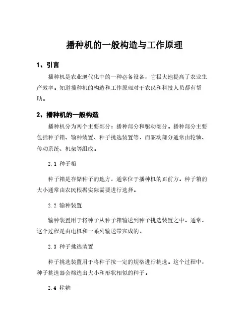
播种机的一般构造与工作原理1、引言播种机是农业现代化中的一种必备设备,它极大地提高了农业生产效率。
知道播种机的构造和工作原理对于农民和科技人员都有帮助。
2、播种机的一般构造播种机分为两个主要部分:播种部分和驱动部分。
播种部分主要包括种子箱、输种装置、种子挑选装置等,而驱动部分通常由轮轴、传动系统、机架等组成。
2.1种子箱种子箱是存储种子的地方,通常位于播种机的正前方。
种子箱的大小通常由农民根据实际需要进行选择。
2.2输种装置输种装置用于将种子从种子箱输送到种子挑选装置之中。
通常,这个过程是由电机和一系列输送带完成的。
2.3种子挑选装置种子挑选装置用于将种子按一定的规格进行挑选。
这个过程中,种子挑选器会筛选出大小和形状相似的种子。
2.4轮轴轮轴是播种机的驱动装置。
它的作用是将机器向前移动。
2.5传动系统传动系统是连接轮轴和电机的部分。
传动系统通常由皮带、齿轮和链条组成。
2.6机架机架是播种机的主体部件。
它是由灰铸铁或者钢板加强而成的,负责连接播种部分和驱动部分。
3、播种机的工作原理播种机的工作原理主要分为两个步骤:挑选种子和播种。
3.1种子挑选在播种之前,种子必须经过挑选。
通常,种子挑选是由一系列运转的轻微振动产生的。
通过振动,农民可以筛选出大小和形状相似的种子,并通过集中到种子挑选装置的筛子之中完成挑选。
3.2播种当种子通过挑选之后,它们将移动到输种装置之中,供播种使用。
通常,这个过程是由电机驱动的输送带完成的。
当种子到达播种位置时,农民按下一个光电控制开关启动播种。
在这个过程中,种子挑选装置会将已经挑选好的种子分配到排好的位置上。
一旦所有的种子都已经播种,播种机将自动停止。
4、总结播种机是农业生产中不能或缺的设备。
了解播种机的构造和工作原理有助于农民和科技人员更好地使用和改进播种机的性能。
这篇文章简要介绍了播种机的一般构造和工作原理,为读者进一步学习和了解相关知识提供了有价值的信息。

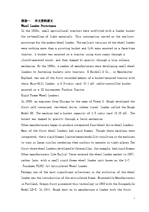
附录一外文资料原文Wheel Loader PrototypesIn the 1920s, small agricultural tractors were outfitted with a loader bucket for re-handling of light materials. This contraption served as the earliest prototype for the modern wheel loader. The earliest versions of the wheel loader were nothing more than a pivoting bucket and lift arms mounted on a farm-type tractor. A bucket was mounted on a tractor using wire ropes through aclutch-operated winch, and then dumped by gravity through a trip release mechanism. By the 1930s, a number of manufacturers were developing small wheel loaders by fastening buckets onto tractors. E.Boydell & Co., in Manchester England, was one of the first recorded makers of a bucket-mounted tractor with their Muir-Hill loader, a 0.5-cubic yard (0.4 m3) cable-controlled bucket mounted on a 28 horsepower Fordson Tractor.Rigid Frame Wheel LoadersIn 1939, an engineer from Chicago by the name of Frank G. Hough developed the first self contained, two-wheel drive, rubber tired, loader called the Hough Model HS. The machine had a bucket capacity of 1/3 cubic yard (0.25 m3). The bucket was dumped by gravity through a latch mechanism.Other manufacturers began to produce integrated four-wheel drive wheel loaders. Many of the first wheel loaders had rigid frames. Though these machines were integrated, their rigid frames limited maneuverability resulting in the machines to turn in large circles rendering them useless to operate in tight places.The first three wheel loaders developed by Caterpillar, for example, had rigid frames. Other manufacturers like Euclid/ Terex entered the wheel loader market in 1957, rather late, with a small rigid frame wheel loader unit known as the L-7.Furukawa FL35I 4x4 Articulated Wheel LoaderPerhaps one of the most significant milestones in the evolution of the wheel loader was the introduction of the articulated frame. Mixermobile Manufacturers in Portland, Oregon first pioneered this technology in 1953 with the Scoopmobile Model LD-5, In 1944, Hough went on to manufacture a loader with the firsthydraulically actuated bucket tilt. This gave the machine the ability to control dumping and the operator could approach a bank in low gear and scoop a full bucket by tilting the bucket back during loading. In 1947, Hough would advance wheel loader development once again when the company developed the world's first four-wheel drive hydraulic wheel loader the HM Model. The model is still considered the forerunner for the modern wheel loader.Mixermobile Manufacturing can be credited with introducing the first wheel loaders with hydraulic motors when it developed the Model H wheel loader in 1952 and the Model HP wheel loader in 1957. These loaders had a single centrally mounted bucket arm.The Tractomotive Corp., founded by Van Dobeus, was another company to introduce the hydraulic wheel loader to the U.S. market. This involved fastening a hydraulic wheel mechanism with hydraulic power to the bucket crowd. This development transformed the wheel loader virtually from a re-handling machine to a digging machine.Front Pivot ArmAs wheel loaders increased in size through the 1950s, concern for safety arose, particularly in the positioning of the loader arm pivot. Positioned behind the operator, the loader arms, as they moved up and down, were in close proximity to the operator. This posed problems. First, the moving arms presented an accident just waiting to happen. Second, the moving parts limited the operators' side visibility, particularly when in a raised position. In the late 1950s, a number of American wheel loader manufacturers were working in collaboration with the National Safety Council to reposition the arm pivot to be in front of the operator rather than behind. Hough was one of the first manufacturers to come up with a new, safer design with the production of their Model HO wheel loader.Other manufacturers quickly followed suit in adopting the front mounted pivot including Caterpillar in 1958, Case in 1959, Allis-Chalmers in 1961 and Michigan in 1962.Large-sized Wheel LoadersAs the 1960s arrived, the trend in wheel loader production focused on larger machines with greater payload capacity. After Caterpillar launched theirsix-cubic yard (4.6-m3) Model 998 in 1963, a number of industry surveys revealed a need for loaders to be much larger than the standard size of five to six cubic yards (3.8 to 4.6 m3). The market was demanding more rugged mobility from loading tools and larger wheel loaders were deemed the solution. Manufacturers began to flood the market with larger sized wheel loaders. Hough Division of International Harvester built the H-400, a wheel loader with a 10-cubic yard (7.6-m3) bucket. Other manufacturers responded by producing loaders with10-cubic yard (7.6-m3) buckets including Caterpillar's 992, the Scoopmobile 1200 and Michigan's 475.Over the years, the industry has continued to push the boundaries in terms of payload capacity. In the 1970s, a number of wheel loaders were showcased at 1975 CONEXPO with increased payload capacity not otherwise seen before in the industry including Hough's 21-cubic yard (16-m3) 580 Payloader and Clark-Michigan's massive 675 wheel loader with a 24-cubic yard (18.3-m3) capacity.[15]In 1986, the record in payload capacity was broken when Kawasaki Heavy Industries Ltd., developed the largest wheel loader with a 25-cubic yard (19-m3) capacity for Japan's Surface Mining Equipment for Coal Technology Research Association. Eventually, other manufacturers including Caterpillar, Komatsu, and LeTourneau would delve into making loaders with capacities of 20 cubic yards (15.3 m3). LeTourneau's Legacy1988 Komatsu WA600-1L Wheel LoaderLeTourneau is a manufacturer that has a reputation of building record-breaking heavy equipment. The company developed and still manufacturers the largest wheel loader in the world, the L-2350.This loader is primarily used in surface mining and boasts a 2300 horsepower machine and an 80-ton, 53-cubic yard (40.5-m3) capacity rock bucket and a breakout force of 266,000 pounds. The height, to the top of the cab and bucket fully raised, is a staggering 43 feet and nine inches (13.23 m). The machine was designed to load 300- to 400-ton plus mining trucks in four to five passes.Le Tourneau's wheel loaders feature diesel-electric drive with DC electric motors in each wheel, a concept developed by LeTourneau himself. In the 1960s, the company started producing very large electric loaders with power to the hoist and bucket tilt transmitted through a rack-and-pinion drive. At first, these huge rack-and-pinion motors were not very commercially successful because the advantage of articulated steering was diminished due to the loader's industrial strength. As a result, few were actually built. One such model was the SL-40 model nicknamed the Monster and measuring 52 feet (16 m) long.The present day line of LeTourneau wheel loaders is derived from the L-700 series electrical drive model first produced in 1968. The L-700 was the forerunner to a series of successful loaders produced in large amounts to this day. The machines have departed from the rack-and-pinion motors but retain the electric drive wheels. Though the rack-and-pinion motor wheel loaders where not big sellers, they did prove to work hard and had a life cycle of more than 20 years. New DevelopmentsToday, electrical loaders exist on the market and function with much the same capacity and versatility as diesel engine or gasoline engine wheel loaders. Wheel loaders also come with a range of attachments such as grapples, forks, and buckets in varying sizes that expand their tasking to include light demolition and tunneling.[21] Some wheel loaders come equipped with ride control, which allows for greater operating speeds on bumpy surfaces.New breakthroughs in adopting hybrid technology to reduce fuel transmissions are underway. In March 2008, Volvo unveiled at CONEXPO, a pre-production prototype of its L220F Hybrid wheel loader. The loader will offer a 10 percent reduction in fuel consumption. The technology has been developed within the Volvo Group and remains confidential and subject to patents. Slated for production in late 2009, the L220F will be the industry's first commercially available hybrid wheel loader.Volvo also has come up with a design concept for a wheel loader called the Gryphin. It is the company's futuristic vision of what a wheel loader may look like wellinto the year 2020. The Gryphin has a hybrid diesel and electric power motor. Replacing the standard transmissions, drivelines, and axles, the Gryphin will feature electrical motors inside each wheel which will make it run quieter than current models. The cab of the Gryphin is also unique and entirely composed of glass that will provide the operator with a greater range of visibility on all sides.How it WorksA wheel loader today is comprised of a pivoted frame, usually articulated, with the engine mounted over the rear wheels, and a cab or canopy resting over the front or rear end frame. The pivot arrangement of the machine is key in giving the wheel loader the capability to maneuver and work in small turning circles. 1974 W14 Wheel LoaderWheel loaders are segmented in the market according to their horsepower. Compact wheel loaders are loaders with 80 horsepower or less, and then the classification is broken down accordingly from 80 to 150 horsepower, 150 to 200 horsepower and 200 to 250 horsepower.Power is supplied from a diesel engine through a torque converter and power shift gears to drive the wheels. Most wheel loaders are now four-wheel drive requiring that all wheels be of the same size but the machines can be operated in two-wheel drive too. Rear wheel drive enhances the machine's digging capability while front wheel drive enables better traction when carrying a full bucket. SpecificationsIn the equipment industry a set of specification criteria are used to measure a wheel loader's performance capacity and usefulness for handling certain construction applications. These include bucket features including the size of the bucket and cutting edges or teeth, tires and their ability to provide traction, tipping load and counterweight, speed, and breakout force. Breakout force is the most-quoted specification for wheel loaders and provides an indication of a wheel loader's digging ability.HistoryGeneral Services and Workshop FacilitiesGough Gough & Hamer has operated Engineering and Manufacturing divisions since the mid 1950's. Since the 1960's and up to 1989, engineering work was carried out primarily by the Gough Gough & Hamer Manufacturing Division, which specialised in the assembly of Hyster and Caterpillar machines. In the 1980's the role was expanded to include in house steel fabrication of frames for Hyster and Caterpillar machines. This included all aspects of production, from cutting plate to machining. This work was made possible by innovative weld fixtures designed by Andrew Gallington, who later established systems and planning for the computerised manufacturing management system. Machines assembled during this period include Hyster Electric Lift Trucks, H40XL up to H275H machines. Caterpillar machines built under the Fieldchief name ranged from 910 to 966 Wheel Loaders, 518 Log Skidders and 120G/130G Graders.In 1988 Bill Cannell was employed by Gough Gough & Hamer's Christchurch branch to manage the production of Transmix Concrete Mixers. Gough Gough and Hamer now accounts for 70% of the New Zealand market in Transit Concrete Mixer. At about this time, Hyster and Caterpillar machines were able to be imported into New Zealand fully built up. This lead to the close of Gough Gough & Hamer's Manufacturing Division and the engineering resources where then passed over to Gough Gough & Hamer's Christchurch branch. The Manufacturing Division's key staff were transferred to Christchurch branch, and a number of new staff were employed with specialised knowledge of the Transmix Range. the new staff included Charlie Greatbatch, Gough Engineering's Works Manager, and Neil Seales, the Machine Shop Forman.In 1990 Gough Gough & Hamer added Fieldchief Logging Forks designed by Andrew Gallington to its range of products, as well as a number of other custom designed products. In 1994 Gough Engineering was established as a business unit of Gough, Gough & Hamer to specialise in the design and manufacture of existing Gough Gough & Hamer products such as Fieldchief Buckets and Log Forks, Transmix Concrete mixers and Concrete Batch Plants. As well as its own designed products, Gough Engineering also established itself as a project steel fabricator buildingconveyers, bins and screw conveyors.In 1995 Gough Engineering included a 3D CAD program to its resources and Solid Modelling in 1998. The introduction of CAD improved Gough Engineering's product design flexibility and resulted in an ever increasing range of products, such as Automatic Batching Plants, Cement Silos, wheel loader and excavator buckets as well as custom design and build projects.In 1996 Gough Engineering established a site in Auckland, which quickly expanded and required a new workshop to be built in 2000.In 1999 Gough Engineering installed the largest CNC Profile cutter in the South Island to cut its ever increasing product range.Fieldchief ProductsGough Gough and Hamer has built a wide range of products under the Fieldchief brand name for the earthmoving, processing and construction industries for over fifty years. From the early 1970's to 1989 Gough Gough & Hamers Manufacturing Division assembled Caterpillar machines and manufactured a number of components due to import regulations on wheeled machines. During this period Fieldchief became synonymous Caterpillar performance and quality. In the early 1980's Manufacturing Division began in-house steel fabrication of Wheel Loader, Log Skidder and Grader frames. As import regulations were dropped the Fieldchief name was applied to Buckets, Log Forks and attachments currently manufactured by Gough Engineering.The oldest Fieldchief product that we know of is a Fieldchief Swamp Plough serial number GH5000/5 which is located at Brayshaw Historical Park near Blenheim. We still have a copy of the blue prints should you need one. The plough was manufactured in the 1950's and is in excellent condition and no doubt will remain that way. Brayshaw Historical Park is well worth a visit for machinery enthusiasts as the collection includes engines of all types most of which are in working order.Rippers and Blades were first produced in 1966 followed in 1972 with the assembly of 950A and 966C wheel loaders. In 1981 930 and 920 wheel loaders were added.During this period a number of different wheel loader buckets were produced. Other parts that were made locally include hydraulic rams, pins and bushes and a wide range of castings. Up until the 1980's most of the steel fabrication was supplied by local steel fabricators, the assembly of machines being the main activity. As new models were released the Manufacturing Division established its own steel fabrication workshop. The 950B was the first of the new design Caterpillar machines to be made in 1984; major fabrications built included the bucket, lift arm, loader frame, ROPS Cab and engine frame. Other wheel loaders produced included 966D,E, 950E, 936,926,916. In 1981 130G Graders were added to the product range followed by 120G's. 518 and 528 were also produced.In 1989 Gough Gough & Hamer's Manufacturing Division closed which could have seen the end of the Fieldchief name if not for Goughs Christchurch Branch offering to employ staff from Manufacturing Division until 1994 when Gough Engineering was established. During this time Caterpillar buckets were manufactured under a revised licence agreement with Caterpillar which ended in 1996. Gough Engineering began building to its own drawings and currently offers over 130 different wheel loader and excavator buckets, Forestry Body kits and a wide range of custom products. By drawings the buckets ourselves we gained insight often taken for granted that allowed custom designed products to be produced economically.In 1990 the first Fieldchief Log Fork was design after consulting with a wide range of logging contractors a process that continues today to continually improve the product. In 1995 3D CAD drawings system was introduced followed by solid modelling and in-house CNC profile cutting in 1999. Backed by its history and manufacturing systems Gough Engineering is able to supply standard and custom designed products for Caterpillar machines. Fieldchief product now covers a wide range of application and machines.附录二:中文翻译轮式装载机的典型20 世纪 20 年代,小型农用拖拉机都配备的轻质材料 re-handling 装载机铲斗。
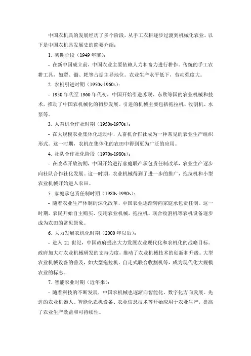
中国农机具的发展经历了多个阶段,从手工农耕逐步过渡到机械化农业。
以下是中国农机具发展史的简要介绍:1. 初期阶段(1949年前):-在新中国成立前,中国农业主要依赖人力和畜力进行耕作。
传统的手工农耕工具,如犁、锄、耙等占据主导地位。
农业生产水平低下,劳动强度大。
2. 农机引进时期(1950s-1960s):-1950年代至1960年代初,中国开始引进苏联、东欧等国的农业机械和技术,推动了中国农机械化的初步发展。
引进的机械主要包括拖拉机、收割机、水泵等。
3. 人畜机合作社时期(1950s-1970s):-在大规模农业集体化运动中,人畜机合作社成为一种常见的农业生产组织形式。
这一时期,农机在集体化的农田中得到更为广泛的应用。
4. 社队合作社化阶段(1970s-1980s):-在改革开放初期,中国开始进行家庭联产承包责任制改革,农业生产逐步向社队合作社化发展。
这一时期,农业机械得到了进一步的推广,拖拉机和小型农业机械开始进入农田。
5. 家庭承包责任制时期(1980s-1990s):-随着农业生产体制的深化改革,中国农业逐渐转向家庭承包责任制。
这一时期,农民开始自主购买、使用农业机械,拖拉机、联合收割机等农机设备逐步成为农田的常见景象。
6. 大力发展农机化时期(2000年以后):-进入21世纪,中国政府提出大力发展农业现代化和农机化的战略目标。
政府加大对农业机械研发的支持力度,推动了农业机械技术的创新和升级。
大型农业机械设备的普及,如大型拖拉机、自走式联合收割机等,成为现代化大规模农业的标志。
7. 智能农业时期(近年来):-随着科技的不断发展,中国农机械也逐渐向智能化、数字化方向发展。
先进的农业机器人、智能化农机设备、农业信息技术等开始应用于农业生产,提高了农业生产效益和可持续性。
总体而言,中国农机具发展经历了从传统手工农耕到现代化农业机械化的漫长历程,取得了显著的进步。
在未来,随着科技的不断创新,农业机械将继续朝着智能、高效、可持续的方向发展。
英文原文Basic Machining Operations and Cutting TechnologyBasic Machining OperationsMachine tools have evolved from the early foot-powered lathes of the Egyptians and John Wilkinson's boring mill. They are designed to provide rigid support for both the workpiece and the cutting tool and can precisely control their relative positions and the velocity of the tool with respect to the workpiece. Basically, in metal cutting, a sharpened wedge-shaped tool removes a rather narrow strip of metal from the surface of a ductile workpiece in the form of a severely deformed chip. The chip is a waste product that is considerably shorter than the workpiece from which it came but with a corresponding increase in thickness of the uncut chip. The geometrical shape of workpiece depends on the shape of the tool and its path during the machining operation.Most machining operations produce parts of differing geometry. If a rough cylindrical workpiece revolves about a central axis and the tool penetrates beneath its surface and travels parallel to the center of rotation, a surface of revolution is produced, and the operation is called turning. If a hollow tube is machined on the inside in a similar manner, the operation is called boring. Producing an external conical surface uniformly varying diameter is called taper turning, if the tool point travels in a path of varying radius, a contoured surface like that of a bowling pin can be produced; or, if the piece is short enough and the support is sufficiently rigid, a contoured surface could be produced by feeding a shaped tool normal to the axis of rotation. Short tapered or cylindrical surfaces could also be contour formed.Flat or plane surfaces are frequently required. They can be generated by radial turning or facing, in which the tool point moves normal to the axis of rotation. In other cases, it is more convenient to hold the workpiece steady and reciprocate the tool across it in a series of straight-line cuts with a crosswise feed increment before each cutting stroke. This operation is called planning and is carried out on a shaper. For larger pieces it is easier to keep the tool stationary and draw the workpiece under it as in planning. The tool is fed at each reciprocation. Contoured surfaces can be produced by using shaped tools.Multiple-edged tools can also be used. Drilling uses a twin-edged fluted tool for holes with depths up to 5 to 10 times the drill diameter. Whether thedrill turns or the workpiece rotates, relative motion between the cutting edge and the workpiece is the important factor. In milling operations a rotary cutter with a number of cutting edges engages the workpiece. Which moves slowly with respect to the cutter. Plane or contoured surfaces may be produced, depending on the geometry of the cutter and the type of feed.Horizontal or vertical axes of rotation may be used, and the feed of the workpiece may be in any of the three coordinate directions.Basic Machine ToolsMachine tools are used to produce a part of a specified geometrical shape and precise I size by removing metal from a ductile material in the form of chips. The latter are a waste product and vary from long continuous ribbons of a ductile material such as steel, which are undesirable from a disposal point of view, to easily handled well-broken chips resulting from cast iron. Machine tools perform five basic metal-removal processes: I turning, planning, drilling, milling, and grinding. All other metal-removal processes are modifications of these five basic processes. For example, boring is internal turning; reaming, tapping, and counter boring modify drilled holes and are related to drilling; bobbing and gear cutting are fundamentally milling operations; hack sawing and broaching are a form of planning and honing; lapping, super finishing. Polishing and buffing are variants of grinding or abrasive removal operations. Therefore, there are only four types of basic machine tools, which use cutting tools of specific controllable geometry: 1. lathes, 2. planers, 3. drilling machines, and 4. milling machines. The grinding process forms chips, but the geometry of the abrasive grain is uncontrollable.The amount and rate of material removed by the various machining processes may be I large, as in heavy turning operations, or extremely small, as in lapping or super finishing operations where only the high spots of a surface are removed.A machine tool performs three major functions: 1. it rigidly supports the workpiece or its holder and the cutting tool; 2. it provides relative motion between the workpiece and the cutting tool; 3. it provides a range of feeds and speeds usually ranging from 4 to 32 choices in each case.Speed and Feeds in MachiningSpeeds, feeds, and depth of cut are the three major variables for economical machining. Other variables are the work and tool materials, coolant and geometry of the cutting tool. The rate of metal removal and power required for machining depend upon these variables.The depth of cut, feed, and cutting speed are machine settings that must be established in any metal-cutting operation. They all affect the forces, the power, and the rate of metal removal. They can be defined by comparing them to the needle and record of a phonograph. The cutting speed (V) is represented by the velocity of- the record surface relative to the needle in the tone arm at any instant. Feed is represented by the advance of the needle radially inward per revolution, or is the difference in position between two adjacent grooves. The depth of cut is the penetration of the needle into the record or the depth of the grooves.Turning on Lathe CentersThe basic operations performed on an engine lathe are illustrated. Those operations performed on external surfaces with a single point cutting tool are called turning. Except for drilling, reaming, and lapping, the operations on internal surfaces are also performed by a single point cutting tool.All machining operations, including turning and boring, can be classified as roughing, finishing, or semi-finishing. The objective of a roughing operation is to remove the bulk of the material as rapidly and as efficiently as possible, while leaving a small amount of material on the work-piece for the finishing operation. Finishing operations are performed to obtain the final size, shape, and surface finish on the workpiece. Sometimes a semi-finishing operation will precede the finishing operation to leave a small predetermined and uniform amount of stock on the work-piece to be removed by the finishing operation.Generally, longer workpieces are turned while supported on one or two lathe centers. Cone shaped holes, called center holes, which fit the lathe centers are drilled in the ends of the workpiece-usually along the axis of the cylindrical part. The end of the workpiece adjacent to the tailstock is always supported by a tailstock center, while the end near the headstock may be supported by a headstock center or held in a chuck. The headstock end of the workpiece may be held in a four-jaw chuck, or in a type chuck. This method holds the workpiece firmly and transfers the power to the workpiece smoothly; the additional support to the workpiece provided by the chuck lessens the tendency for chatter to occur when cutting. Precise results can be obtained with this method if care is taken to hold the workpiece accurately in the chuck.Very precise results can be obtained by supporting the workpiece between two centers. A lathe dog is clamped to the workpiece; together they are driven by a driver plate mounted on the spindle nose. One end of the Workpiece is mecained;then the workpiece can be turned around in the lathe to machine the other end. The center holes in the workpiece serve as precise locating surfaces as well as bearing surfaces to carry the weight of the workpiece and to resist the cutting forces. After the workpiece has been removed from the lathe for any reason, the center holes will accurately align the workpiece back in the lathe or in another lathe, or in a cylindrical grinding machine. The workpiece must never be held at the headstock end by both a chuck and a lathe center. While at first thought this seems like a quick method of aligning the workpiece in the chuck, this must not be done because it is not possible to press evenly with the jaws against the workpiece while it is also supported by the center. The alignment provided by the center will not be maintained and the pressure of the jaws may damage the center hole, the lathe center, and perhaps even the lathe spindle. Compensating or floating jaw chucks used almost exclusively on high production work provide an exception to the statements made above. These chucks arereally work drivers and cannot be used for the same purpose as ordinary three or four-jaw chucks.While very large diameter workpieces are sometimes mounted on two centers, they are preferably held at the headstock end by faceplate jaws to obtain the smooth power transmission; moreover, large lathe dogs that are adequate to transmit the power not generally available, although they can be made as a special. Faceplate jaws are like chuck jaws except that they are mounted on a faceplate, which has less overhang from the spindle bearings than a large chuck would have.Introduction of MachiningMachining as a shape-producing method is the most universally used and the most important of all manufacturing processes. Machining is a shape-producing process in which a power-driven device causes material to be removed in chip form. Most machining is done with equipment that supports both the work piece and cutting tool although in some cases portable equipment is used with unsupported workpiece.Low setup cost for small Quantities. Machining has two applications in manufacturing. For casting, forging, and press working, each specific shape to be produced, even one part, nearly always has a high tooling cost. The shapes that may he produced by welding depend to a large degree on the shapes of raw material that are available. By making use of generally high cost equipment but without special tooling, it is possible, by machining; to start with nearly any form of raw material, so tong as the exterior dimensions are great enough, and produce any desired shape from any material. Therefore .machining is usually the preferred method for producing one or a few parts, even when the design of the part would logically lead to casting, forging or press working if a high quantity were to be produced.Close accuracies, good finishes. The second application for machining is based on the high accuracies and surface finishes possible. Many of the parts machined in low quantities would be produced with lower but acceptable tolerances if produced in high quantities by some other process. On the other hand, many parts are given their general shapes by some high quantity deformation process and machined only on selected surfaces where high accuracies are needed. Internal threads, for example, are seldom produced by any means other than machining and small holes in press worked parts may be machined following the press working operations.Primary Cutting ParametersThe basic tool-work relationship in cutting is adequately described by means of four factors: tool geometry, cutting speed, feed, and depth of cut.The cutting tool must be made of an appropriate material; it must be strong, tough, hard, and wear resistant. The tool s geometry characterized by planes and angles, must be correct foreach cutting operation. Cutting speed is the rate at which the work surface passes by the cutting edge. It may be expressed in feet per minute.For efficient machining the cutting speed must be of a magnitude appropriate to the particular work-tool combination. In general, the harder the work material, the slower the speed.Feed is the rate at which the cutting tool advances into the workpiece. "Where the workpiece or the tool rotates, feed is measured in inches per revolution. When the tool or the work reciprocates, feed is measured in inches per stroke, Generally, feed varies inversely with cutting speed for otherwise similar conditions.The depth of cut, measured inches is the distance the tool is set into the work. It is the width of the chip in turning or the thickness of the chip in a rectilinear cut. In roughing operations, the depth of cut can be larger than for finishing operations.The Effect of Changes in Cutting Parameters on Cutting TemperaturesIn metal cutting operations heat is generated in the primary and secondary deformation zones and these results in a complex temperature distribution throughout the tool, workpiece and chip. A typical set of isotherms is shown in figure where it can be seen that, as could be expected, there is a very large temperature gradient throughout the width of the chip as the workpiece material is sheared in primary deformation and there is a further large temperature in the chip adjacent to the face as the chip is sheared in secondary deformation. This leads to a maximum cutting temperature a short distance up the face from the cutting edge and a small distance into the chip.Since virtually all the work done in metal cutting is converted into heat, it could be expected that factors which increase the power consumed per unit volume of metal removed will increase the cutting temperature. Thus an increase in the rake angle, all other parameters remaining constant, will reduce the power per unit volume of metal removed and the cutting temperatures will reduce. When considering increase in unreformed chip thickness and cutting speed the situation is more complex. An increase in undeformed chip thickness tends to be a scale effect where the amounts of heat which pass to the workpiece, the tool and chip remain in fixed proportions and the changes in cutting temperature tend to be small. Increase in cutting speed; however, reduce the amount of heat which passes into the workpiece and this increase the temperature rise of the chip m primary deformation. Further, the secondary deformation zone tends to be smaller and this has the effect of increasing the temperatures in this zone. Other changes in cutting parameters have virtually no effect on the power consumed per unit volume of metal removed and consequently have virtually no effect on the cutting temperatures. Since it has been shown that even small changes in cutting temperature have a significant effect on tool wear rate it is appropriate to indicate how cutting temperatures can be assessed from cutting data.The most direct and accurate method for measuring temperatures in high -speed-steel cutting tools is that of Wright &. Trent which also yields detailed information on temperature distributions in high-speed-steel cutting tools. The technique is based on the metallographic examination of sectioned high-speed-steel tools which relates microstructure changes to thermal history.Trent has described measurements of cutting temperatures and temperature distributions for high-speed-steel tools when machining a wide range of workpiece materials. This technique has been further developed by using scanning electron microscopy to study fine-scale microstructure changes arising from over tempering of the tempered martens tic matrix of various high-speed-steels. This technique has also been used to study temperature distributions in both high-speed -steel single point turning tools and twist drills.Wears of Cutting ToolDiscounting brittle fracture and edge chipping, which have already been dealt with, tool wear is basically of three types. Flank wear, crater wear, and notch wear. Flank wear occurs on both the major and the minor cutting edges. On the major cutting edge, which is responsible for bulk metal removal, these results in increased cutting forces and higher temperatures which if left unchecked can lead to vibration of the tool and workpiece and a condition where efficient cutting can no longer take place. On the minor cutting edge, which determines workpiece size and surface finish, flank wear can result in an oversized product which has poor surface finish. Under most practical cutting conditions, the tool will fail due to major flank wear before the minor flank wear is sufficiently large to result in the manufacture of an unacceptable component.Because of the stress distribution on the tool face, the frictional stress in the region of sliding contact between the chip and the face is at a maximum at the start of the sliding contact region and is zero at the end. Thus abrasive wear takes place in this region with more wear taking place adjacent to the seizure region than adjacent to the point at which the chip loses contact with the face. This result in localized pitting of the tool face some distance up the face which is usually referred to as catering and which normally has a section in the form of a circular arc. In many respects and for practical cutting conditions, crater wear is a less severe form of wear than flank wear and consequently flank wear is a more common tool failure criterion. However, since various authors have shown that the temperature on the face increases more rapidly with increasing cutting speed than the temperature on the flank, and since the rate of wear of any type is significantly affected by changes in temperature, crater wear usually occurs at high cutting speeds.At the end of the major flank wear land where the tool is in contact with the uncut workpiece surface it is common for the flank wear to be more pronounced than along the rest ofthe wear land. This is because of localised effects such as a hardened layer on the uncut surface caused by work hardening introduced by a previous cut, an oxide scale, and localised high temperatures resulting from the edge effect. This localised wear is usually referred to as notch wear and occasionally is very severe. Although the presence of the notch will not significantly affect the cutting properties of the tool, the notch is often relatively deep and if cutting were to continue there would be a good chance that the tool would fracture.If any form of progressive wear allowed to continue, dramatically and the tool would fail catastrophically, i. e. the tool would be no longer capable of cutting and, at best, the workpiece would be scrapped whilst, at worst, damage could be caused to the machine tool. For carbide cutting tools and for all types of wear, the tool is said to have reached the end of its useful life long before the onset of catastrophic failure. For high-speed-steel cutting tools, however, where the wear tends to be non-uniform it has been found that the most meaningful and reproducible results can be obtained when the wear is allowed to continue to the onset of catastrophic failure even though, of course, in practice a cutting time far less than that to failure would be used. The onset of catastrophic failure is characterized by one of several phenomena, the most common being a sudden increase in cutting force, the presence of burnished rings on the workpiece, and a significant increase in the noise level.Mechanism of Surface Finish ProductionThere are basically five mechanisms which contribute to the production of a surface which have been machined. These are:(l) The basic geometry of the cutting process. In, for example, single point turning the tool will advance a constant distance axially per revolution of the workpiecc and the resultant surface will have on it, when viewed perpendicularly to the direction of tool feed motion, a series of cusps which will have a basic form which replicates the shape of the tool in cut.(2) The efficiency of the cutting operation. It has already been mentioned that cutting with unstable built-up-edges will produce a surface which contains hard built-up-edge fragments which will result in a degradation of the surface finish. It can also be demonstrated that cutting under adverse conditions such as apply when using large feeds small rake angles and low cutting speeds, besides producing conditions which lead to unstable built-up-edge production, the cutting process itself can become unstable and instead of continuous shear occurring in the shear zone, tearing takes place, discontinuous chips of uneven thickness are produced, and the resultant surface is poor. This situation is particularly noticeable when machining very ductile materials such as copper and aluminum.(3) The stability of the machine tool. Under some combinations of cutting conditions; workpiece size, method of clamping ,and cutting tool rigidity relative to the machine toolstructure, instability can be set up in the tool which causes it to vibrate. Under some conditions this vibration will reach and maintain steady amplitude whilst under other conditions the vibration will built up and unless cutting is stopped considerable damage to both the cutting tool and workpiece may occur. This phenomenon is known as chatter and in axial turning is characterized by long pitch helical bands on the workpiece surface and short pitch undulations on the transient machined surface.(4)The effectiveness of removing swarf. In discontinuous chip production machining, such as milling or turning of brittle materials, it is expected that the chip (swarf) will leave the cutting zone either under gravity or with the assistance of a jet of cutting fluid and that they will not influence the cut surface in any way. However, when continuous chip production is evident, unless steps are taken to control the swarf it is likely that it will impinge on the cut surface and mark it. Inevitably, this marking besides looking.(5)The effective clearance angle on the cutting tool. For certain geometries of minor cutting edge relief and clearance angles it is possible to cut on the major cutting edge and burnish on the minor cutting edge. This can produce a good surface finish but, of course, it is strictly a combination of metal cutting and metal forming and is not to be recommended as a practical cutting method. However, due to cutting tool wear, these conditions occasionally arise and lead to a marked change in the surface characteristics.Limits and TolerancesMachine parts are manufactured so they are interchangeable. In other words, each part of a machine or mechanism is made to a certain size and shape so will fit into any other machine or mechanism of the same type. To make the part interchangeable, each individual part must be made to a size that will fit the mating part in the correct way. It is not only impossible, but also impractical to make many parts to an exact size. This is because machines are not perfect, and the tools become worn. A slight variation from the exact size is always allowed. The amount of this variation depends on the kind of part being manufactured. For examples part might be made 6 in. long with a variation allowed of 0.003 (three-thousandths) in. above and below this size. Therefore, the part could be 5.997 to 6.003 in. and still be the correct size. These are known as the limits. The difference between upper and lower limits is called the tolerance.A tolerance is the total permissible variation in the size of a part.The basic size is that size from which limits of size arc derived by the application of allowances and tolerances.Sometimes the limit is allowed in only one direction. This is known as unilateral tolerance.Unilateral tolerancing is a system of dimensioning where the tolerance (that is variation) is shown in only one direction from the nominal size. Unilateral tolerancing allow the changing of tolerance on a hole or shaft without seriously affecting the fit.When the tolerance is in both directions from the basic size it is known as a bilateral tolerance (plus and minus).Bilateral tolerancing is a system of dimensioning where the tolerance (that is variation) is split and is shown on either side of the nominal size. Limit dimensioning is a system of dimensioning where only the maximum and minimum dimensions arc shown. Thus, the tolerance is the difference between these two dimensions.Surface Finishing and Dimensional ControlProducts that have been completed to their proper shape and size frequently require some type of surface finishing to enable them to satisfactorily fulfill their function. In some cases, it is necessary to improve the physical properties of the surface material for resistance to penetration or abrasion. In many manufacturing processes, the product surface is left with dirt .chips, grease, or other harmful material upon it. Assemblies that are made of different materials, or from the same materials processed in different manners, may require some special surface treatment to provide uniformity of appearance.Surface finishing may sometimes become an intermediate step processing. For instance, cleaning and polishing are usually essential before any kind of plating process. Some of the cleaning procedures are also used for improving surface smoothness on mating parts and for removing burrs and sharp corners, which might be harmful in later use. Another important need for surface finishing is for corrosion protection in a variety of: environments. The type of protection procedure will depend largely upon the anticipated exposure, with due consideration to the material being protected and the economic factors involved.Satisfying the above objectives necessitates the use of main surface-finishing methods that involve chemical change of the surface mechanical work affecting surface properties, cleaning by a variety of methods, and the application of protective coatings, organic and metallic.In the early days of engineering, the mating of parts was achieved by machining one part as nearly as possible to the required size, machining the mating part nearly to size, and then completing its machining, continually offering the other part to it, until the desired relationship was obtained. If it was inconvenient to offer one part to the other part during machining, the final work was done at the bench by a fitter, who scraped the mating parts until the desired fit was obtained, the fitter therefore being a 'fitter' in the literal sense. J It is obvious that the two parts would have to remain together, and m the event of one having to be replaced, the fitting would have to be done all over again. In these days, we expect to be able to purchase a replacement fora broken part, and for it to function correctly without the need for scraping and other fitting operations.When one part can be used 'off the shelf' to replace another of the same dimension and material specification, the parts are said to be interchangeable. A system of interchangeability usually lowers the production costs as there is no need for an expensive, 'fiddling' operation, and it benefits the customer in the event of the need to replace worn parts.Automatic Fixture DesignTraditional synchronous grippers for assembly equipment move parts to the gripper centre-line, assuring that the parts will be in a known position after they arc picked from a conveyor or nest. However, in some applications, forcing the part to the centre-line may damage cither the part or equipment. When the part is delicate and a small collision can result in scrap, when its location is fixed by a machine spindle or mould, or when tolerances are tight, it is preferable to make a gripper comply with the position of the part, rather than the other way around. For these tasks, Zaytran Inc. Of Elyria, Ohio, has created the GPN series of non- synchronous, compliant grippers. Because the force and synchronizations systems of the grippers are independent, the synchronization system can be replaced by a precision slide system without affecting gripper force. Gripper sizes range from 51b gripping force and 0.2 in. stroke to 40Glb gripping force and 6in stroke. GrippersProduction is characterized by batch-size becoming smaller and smaller and greater variety of products. Assembly, being the last production step, is particularly vulnerable to changes in schedules, batch-sizes, and product design. This situation is forcing many companies to put more effort into extensive rationalization and automation of assembly that was previouslyextensive rationalization and automation of assembly that was previously the case. Although the development of flexible fixtures fell quickly behind the development of flexible handling systems such as industrial robots, there are, nonetheless promising attempts to increase the flexibility of fixtures. The fact that fixtures are the essential product - specific investment of a production system intensifies the economic necessity to make the fixture system more flexible.Fixtures can be divided according to their flexibility into special fixtures, group fixtures, modular fixtures and highly flexible fixtures. Flexible fixtures are characterized by their high adaptability to different workpieces, and by low change-over time and expenditure.There are several steps required to generate a fixture, in which a workpiece is fixed for a production task. The first step is to define the necessary position of the workpiece in the fixture, based on the unmachined or base pan, and the working features. Following this, a combination of stability planes must be selected. These stability planes constitute the fixture configuration in which the workpiece is fixed in the defined position, all the forces or torques are compensated,。
第三章 播种机械第一节 概述播种是农业生产过程中六大环节之一,播种机械化是农业机械化过程中最为复杂,也是最为艰巨的工作。
播种机械所面对的播种方式、作物种类、品种变化繁多,这就需要播种机械有较强的适应性和能满足不同种植要求的工作性能。
一、 播种方法我国地域辽阔,作物生产的环境、条件、种植方式等多种多样,南北方有着明显的差异。
北方表现为旱地作业,以向土壤中播入规定量的种子为主要种植手段,所用机具为播种机械,这样可充分利用土壤中的水分和温度使之出苗、生长,适时播种成为关键。
而南方则表现为水田作业,种植方式主要是幼苗移栽,所用机械为栽植机械或插秧机械。
但是,近几年来有些作物的种植方式发生了逆转,如玉米、棉花出现了工厂化育苗然后进行移栽,且已证明在干旱缺水地区大有取代播种机的趋势。
而世代以栽植为主要种植手段的水稻、地瓜等作物,由于种植技术的革新现在出现了直播(水稻须进行种子催芽处理,地瓜须进行防腐处理),可大大简化生产过程,降低作业周期和生产成本。
上述一些先进的种植手段由于技术、设备、条件、环境等因素的限制,目前尚处于小范围试用阶段,真正用于现阶段农业生产的种植方式仍然是经典的和传统的,总结起来大致有以下几种方式:一、播种方法1、条播:将种子按要求的行距、播量和播深成条的播入土壤中,然后进行覆土镇压的方式。
种子排出的形式为均匀的种子流,主要应用于谷物播种:小麦、谷子、高粱、油菜等。
2、穴播:(点播):按照要求的行距、穴距、穴粒数和播深,将种子定点投入种穴内的方式。
主要应用于中耕作物播种:玉米、棉花、花生等。
与条播相比,节省种子、减少出苗后的间苗管理环节,充分利用水肥条件,提高种子的出苗率和作业效率。
3、精密播种:按精确的粒数、间距、行距、播深将种子播入土壤的方式。
是穴播的高级形式。
4、撒播:将种子按要求的播量撒布于地表的方式。
一般作物播种很少使用这种方法,多用于大面积种草、植树造林的飞机撒播。
二、 播种机械的类型和一般构造1、类型:谷物条播机,中耕作物穴播机、精密播种机(该机在结构上与穴播机及其相似)。
黑龙江工程学院本科生毕业设计 1 附 录 Seeder history and introduction he first century B.C., China has good, this is to promote the use of the world's earliest drill machine, today is still in the north of equal applications. 1636 in Greece first Taiwan machine made. In 1830, russians in livestock HuaLi more on LiBo machine made. 1860 years later, the countries such as Britain and started mass production work grain suitable drill. After the 20 th century have appeared traction and hanging drill machine, and the use of grain strength of the machine. 50 s development precision machine. China from the 1950 s to introduce grain suitable drill, cotton machine, etc. 60 s has developed into a suspension type grain machine, centrifugal machine, universal frame and gas suction style such as machine machine DuoZhong type, and grinding lines to the development of the device. In the 70 s, has formed the seeding machine general machine and grain joint seeder two series, and has developed precision machine. Europe first Taiwan machine made in 1636 in Greece. In 1830, the russians in livestock HuaLi more on the sowing device LiBo machine made. Britain, the United States and other countries in 1860 years later started mass production work grain suitable drill. 20 centuries later period, there appeared the traction and hanging drill machine, and the use of grain strength of the machine. In 1958, Norway appear first Taiwan centrifugal machine, 50 s gradually developed all kinds of precision machine. China in the 1950 s introduced from abroad grain suitable drill, cotton machine, the '60 s and has successfully developed suspension type grain machine, centrifugal machine, universal frame and gas suction style such as machine machine DuoZhong models, and has developed grinding lines of the device. In the 70 s, has formed the seeding machine general machine and grain joint seeder two series and production. For grain and intertillage crops, grasses, and all kinds of vegetables with suitable drill and XueBo machine are already widely used. At the same time, also has developed DuoZhong precision machine. Corn is uniform, sowing machine depth is consistent, stable, cover earth good row 黑龙江工程学院本科生毕业设计 2 spacing, save seeds, work efficiency higher characteristic. The correct use of machine should pay attention to the following points: master 10 1 in the maintenance of the field before operation to clean up the trash and sowing the device on the open ditch the winding grass, clay, ensure good condition, and the tractors and the transmission, the rotation of the machine parts, according to the requirements of the manual filling lubricating oil, especially every time before operation should pay attention to the transmission chain lubrication and a tight situation on the fastening bolts and sowing. 2 frame can't tilt seeder and tractors to hook up may not be tilt, work should make frame a state level before and after. 3 do well adjusted according to the instructions of the rules and regulations of the main requirements, the rate, open ditch is the spaced, open ditch crackdown on the depth of the wheel turns the soil suitable. 4 attention and good seed to join the seeds of seeds, where there is no box small, Bi, miscellaneous, to ensure the effectiveness of the seeds; Second seed box with kind of quantity of at least to add to that cover the box of entrance, in order to ensure the smooth. 5 test broadcasts to ensure the quality of the large area, seeded before sowing, must hold to test broadcasts 20 meters, observe the machine work. Please agricultural technology personnel, local farmers consultation, testing confirmed that meet local agricultural demands, and then carry on large area sown. 6 note of uniform linear driving NongJiShou choose the assignment walking routes, should guarantee and kind of and mechanical in and out of convenience, planting time to pay attention to more uniformly and in a straight line, line, not fast and slow or stop the leak, lest the replay, broadcast; To prevent the open ditch jams, the rise and fall of machine to are on the march, when turning back or operation should be filed seeder. 7 was the first out first broadcast to rolling out, out, was hard by deep too shallow. 8 often observed planting time constant observation of the device, open ditch device, the cover and transmission's work, such as the clogging, clay, winding grass, seed cover lax, shall be ruled out in time. Adjustment, repair, lubrication or cleaning the winding grass, etc, must be in after parking. 9 protect parts of the machine work, it is strictly prohibited to scale back or sharp turn and the ascension of the machine should slow or land, lest attaint parts. 10 note seed box when the seeds of the homework seed shall be not less than 1/5 of the