solidworks面向制造和装配的产品设计说明
- 格式:ppt
- 大小:1.90 MB
- 文档页数:38


solidworks案例教程SolidWorks案例教程导言SolidWorks是一款广泛应用于机械设计和工程领域的三维CAD软件。
它提供了一整套强大的工具和功能,帮助用户设计、模拟、分析和制造各种产品。
在本篇教程中,我们将介绍一些实际案例,以帮助您熟悉和掌握SolidWorks的使用。
案例一:零件设计在这个案例中,我们将设计一个简单的机械零件。
假设我们需要设计一个机械零件,具体要求如下:1. 长方体形状,尺寸为100mmx50mmx30mm;2. 顶部有一个直径为10mm的孔;3. 零件材质为铝合金。
首先,打开SolidWorks软件并创建一个新的零件文件。
然后,按照下面的步骤进行设计:1. 使用“长方体”工具创建一个100mmx50mmx30mm的长方体;2. 使用“圆柱体”工具在顶部创建一个直径为10mm的孔;3. 使用“填充”工具将零件表面设置为铝合金材质。
完成上述步骤后,保存并导出零件文件。
您现在已经成功设计了一个简单的机械零件。
在SolidWorks中可以进一步对零件进行分析、模拟和制造等操作。
案例二:装配设计在这个案例中,我们将学习如何使用SolidWorks进行装配设计。
假设我们需要设计一个简单的机械装配,具体要求如下:1. 包含两个零件:一个底座和一个支架;2. 底座和支架之间通过两个螺栓连接;3. 完成装配后,需要进行装配分析。
以下是设计步骤:1. 创建一个新的装配文件,并将底座和支架导入到装配文件中;2. 使用“配合关系”工具将底座和支架对齐,并使用“约束关系”工具将它们连接;3. 使用“螺栓”工具在底座和支架之间创建两个螺栓连接;4. 完成装配后,进行装配分析,检查装配的可行性和稳定性。
通过上述步骤,您已经成功地完成了一个简单的机械装配设计。
这个案例不仅帮助您熟悉SolidWorks中的装配设计工具,还让您了解了如何使用装配分析工具来优化设计。
案例三:静态分析在这个案例中,我们将学习如何使用SolidWorks进行静态分析。


Solidworks最全面的介绍简介Solidworks是一款广泛应用于机械设计和工程领域的三维计算机辅助设计(CAD)软件。
该软件由达索系统公司开发,提供了多种功能和工具,能够帮助设计师轻松地创建、仿真和分析三维模型。
本文将对Solidworks的功能和特点进行全面介绍。
功能与特点1. 三维建模:Solidworks提供了强大的三维建模功能,可以通过直观的用户界面轻松地创建和编辑复杂的三维模型。
用户可以使用几何形状和实体建模工具来设计各种物体,如零件、装配体和表面模型。
2. 零件和装配设计:Solidworks支持零件和装配设计,用户可以创建各种机械部件,并将它们组装成装配体。
用户可以通过轻松的拖放操作实现部件之间的关联和运动仿真。
此外,Solidworks还提供了装配约束和碰撞检测等功能,确保设计的可靠性和安全性。
3. 二维图纸与标注:Solidworks使用户能够快速生成详细的二维图纸,以便在生产过程中进行制造和装配。
用户可以将三维模型转换为二维图纸,并添加标注和尺寸以满足制造要求。
4. 仿真与分析:Solidworks具备强大的仿真和分析功能,用户可以对设计进行结构、流体和热力学等方面的分析。
通过模拟真实环境下的工作条件,用户可以评估设计的性能和可靠性,并进行设计优化。
5. 文件交换与数据管理:Solidworks支持多种文件格式的导入和导出,包括STEP、IGES、DWG和PDF等。
此外,Solidworks还提供了数据管理工具,方便用户对设计文件进行版本控制和共享。
6. 模型库和资源:Solidworks内置了丰富的零件、材料和纹理库,用户可以轻松获取和应用于设计中,节省了大量的设计时间。
应用领域Solidworks在产品设计和制造领域得到了广泛的应用。
它可以用于设计和开发各种产品,包括汽车零部件、航空航天器件、消费电子产品、医疗设备等。
同时,Solidworks也被广泛应用于工程教育和研究领域,用于培养学生的设计思维和工程技能。

SolidWorks装配体什么是SolidWorks装配体SolidWorks是一种专业的三维计算机辅助设计(CAD)软件,可用于创建和编辑三维模型。
在SolidWorks中,可以通过使用装配体将多个组件组合在一起,以创建复杂的机械装配。
装配体是由多个部件组成的,每个部件都可以包含形状和属性。
创建SolidWorks装配体的步骤1.打开SolidWorks软件并创建一个新的装配体。
2.确定装配体的坐标系及初始位置。
可以使用坐标系来确定装配体内各部件的位置和方向。
3.导入或创建所需的部件。
在装配体中,可以导入预先创建好的部件文件,也可以直接在装配体中创建部件。
4.将部件插入到装配体中。
通过选择部件文件并将其插入到装配体中,可以将部件放置在所需的位置上。
5.对部件进行约束。
通过添加约束将部件固定在所需的位置和方向上。
约束可以是基于尺寸、几何形状或其他条件。
6.检查装配体的运动性和完整性。
可以使用装配体运动模拟工具查看部件之间的运动以及装配体的可操作性。
7.添加必要的修饰和特征。
可以根据需要对装配体进行细化和修改,以添加必要的细节、表面处理等。
8.导出和保存装配体。
最后,将装配体导出为适当的文件格式,并保存为适当的命名约定。
SolidWorks装配体的优势•便于可视化和协作:SolidWorks装配体允许用户以三维形式查看装配体及其组件,以便更直观地了解整个装配体的结构和关系。
这使得团队成员和相关方能更好地理解和参与装配体设计和开发过程。
•快速修改和更新:使用SolidWorks装配体,可以快速修改和更新组件和装配体。
这是因为所有相关组件都在同一装配体文件中,并且可以直接对其进行编辑和更新,而不必打开每个组件文件。
•省时省力的融合:通过将多个部件组合成一个装配体,可以将一些重复的操作和设计步骤省略掉。
•功能强大的分析工具:SolidWorks配备了强大的分析工具,如运动模拟、碰撞检测、应力分析等,可以帮助工程师评估装配体的性能和可靠性,以及解决潜在的设计问题。

solidworks 装配体设计树隐藏配合关系概述说明1. 引言1.1 概述在SolidWorks装配体设计中,配合关系是非常重要的一部分。
它定义了各个零件之间的连接方式和相互作用,直接影响到装配体的功能性和稳定性。
然而,在大型装配体中,设计树会变得非常庞大繁杂,使得查找和管理配合关系变得困难。
为了提高设计效率并简化装配体结构,我们需要学习如何隐藏不必要或复杂的配合关系。
1.2 文章结构本文将首先介绍SolidWorks装配体设计概述,包括其定义、特点以及在实际工程应用中的重要性。
随后详细介绍SolidWorks设计树的基本功能和操作方法,并着重讨论如何隐藏配合关系对于提高设计效率和简化装配体结构的意义。
接下来将针对实现隐藏配合关系的三种具体方法进行详细解释和演示,并通过应用案例分析-汽车发动机装配体设计来展示其实际应用价值。
最后,从这篇文章中总结出核心观点并给出未来研究方向的探索。
1.3 目的本文旨在帮助读者了解SolidWorks装配体设计树隐藏配合关系的重要性以及实现方法。
通过学习如何隐藏配合关系,读者可以更好地管理和控制装配体设计树,提高工作效率,并在实际应用中解决复杂装配体设计中遇到的问题。
2. SolidWorks装配体设计树隐藏配合关系2.1 装配体设计概述SolidWorks是一款三维计算机辅助设计(CAD)软件,广泛应用于装配体设计。
在装配体设计中,不同零件之间的配合关系非常重要。
通过正确的配置和对零件的包容性分析,可以确保装配体的正常运作。
这篇文章将重点介绍SolidWorks 中隐藏配合关系的方法与技巧。
2.2 SolidWorks设计树介绍SolidWorks的设计树是一个展示模型组成结构和层次的功能面板,可以方便地管理和编辑装配体。
设计树上显示了装配体中每个组件、子组件以及其特征、阵列等详细信息。
通过查看设计树,用户可以了解到不同零件之间的父子关系,并进行相应的操作。
2.3 隐藏配合关系的重要性在大型复杂装配体中,为了简化视图和提高模型加载速度,有时需要隐藏某些部分或者部分零件之间的密集配合关系。


solidworks功能介绍SolidWorks是一种三维计算机辅助设计(CAD)软件,它被广泛应用于机械设计、工程分析和制造领域。
SolidWorks的功能非常丰富,下面是一些主要的功能介绍:1. 零件建模:SolidWorks可以让用户创建高质量的三维实体模型。
它提供了广泛的建模工具,包括 extrude、revolve、sweep、loft、fillet等,使用户可以快速准确地创建复杂的零件。
2. 性能评估:SolidWorks具有内置的分析工具,可以帮助用户评估设计的性能。
例如,它可以进行应力和位移的分析,以确保设计可以承受实际工作条件下的负载。
此外,它还可以进行流体力学分析、热分析和振动分析等。
3. 装配建模:SolidWorks可以创建包含多个零件的装配模型。
它提供了装配约束工具,使用户可以将零件定位和连接在一起。
此外,它还可以检查装配的干涉并解决干涉问题,确保装配的正确性。
4. 图纸制作:SolidWorks可以将三维模型转换为二维工程图纸,以便用于制造和装配。
它提供了一整套的绘图工具,包括尺寸、注释、符号等,使用户可以轻松地创建精确和可读的图纸。
5. 数据管理:SolidWorks具有强大的数据管理功能,可以帮助用户组织和管理设计数据。
它可以跟踪设计更改、版本控制和文档审查等,确保设计团队的协作和数据完整性。
6. 高级渲染:SolidWorks可以创建逼真的渲染图像,以展示设计的外观和材质。
它提供了多种材质、光源和相机设置,使用户可以为设计创建专业水准的渲染图像。
7. CNC加工:SolidWorks可以生成适用于计算机数控(CNC)机床的切削路径。
它可以将设计转换为G代码,以便于机床进行加工。
此外,它还可以进行切削力分析,以确保加工过程的稳定性和可靠性。
8. 管线与线路设计:SolidWorks可以进行管线和线路的设计。
它提供了一系列的设计工具和符号库,使用户可以轻松地创建复杂的管线和线路布局。


CADCAM课程作业内容:建模制作人:赵超目录序言 (3)1、设计题目: (4)2、装配体的分析: (4)2-1 零件分析 (5)2-2部分零件相关尺寸 (5)3、零件建模分析和过程 (8)3-1 压盖 (8)3-2、底座 (8)3-3、轴瓦 (9)3-4、楔子 (9)3、装配体建模分析和过程 (10)5、小结体会 (11)6、参考文献 (12)序言随着计算机的迅猛发展,工程界的迫切需要,计算机辅助绘图(Computer Aided Drawing)应运而生。
当代CAD软件系统已经成为机械产品设计的重要手段和工具,随着CAD技术的不断进步,市场主流CAD软件系统已经逐步从支持二维图纸设计发展成支持三位实体建模的工具,利用主流三维CAD软件进行机械设计,有利于实现产品创新,同时设计的三维零件模型可以直接向后续工具传递数据进行有限元分析,工艺分析和加工仿真等工作,从而可以有效的提高机械设计率。
这次课程实践给了我一次很好的机会去接触这类软件,锻炼了自己分析问题、解决问题的能力,为今后参加祖国的“四化”建设打下一个良好的基础。
但由于能力所限,设计尚有许多不足之处,恳请老师给予指导。
1、设计题目:轴承座:装在汽轮机汽缸本体或基础上用来支撑轴承的构件。
总任务是通过建模、仿真等步骤了解一个工件的加工流程。
在小组中,我的任务是建模。
2、装配体的分析:该装配体为一个轴承座,轴承座的作用是稳定轴承及其所连接的回转轴,确保轴和轴承内圈平稳回转避免因承载回转引起的轴承扭动或跳动。
2-1 零件分析该装配体共有10个零件,分别是:螺母*2、螺栓*2、压盖、轴瓦*2、底座、楔子*22-2部分零件相关尺寸压盖:底座:轴瓦:3、零件建模分析和过程3-1 压盖先画草图,然后通过四次拉伸,两次圆角建成3-2、底座先画草图,然后通过四次向外拉伸,三次向内拉伸,再三次圆角建成。
3-3、轴瓦先画草图,然后通过旋转、一次拉伸切除,一次镜像,两次倒角建成。

Solidworks机械设计简介Solidworks是一款专业的3D机械设计软件,广泛应用于各个行业的机械设计领域。
它提供了先进的建模和设计工具,使设计师能够快速创建复杂的机械部件和装配体,并进行仿真分析。
本文将介绍Solidworks的主要功能和应用领域,并提供一些使用Solidworks进行机械设计的最佳实践。
功能介绍Solidworks具有许多强大的机械设计功能,以下是一些主要功能的介绍:1. 3D建模Solidworks提供了先进的3D建模工具,使设计师能够创建几何复杂的机械部件。
它支持几何特征建模(如拉伸、旋转、倒角等)、曲面建模和直接建模等多种建模方法。
此外,Solidworks还提供了大量的实体建模和线框建模工具,使设计师能够以不同的方式创建模型。
2. 装配设计Solidworks使设计师能够创建复杂的装配体,包括多个零部件的组合。
设计师可以使用Solidworks的装配功能将各个零部件组装在一起,并对它们之间的运动和约束进行定义。
同时,Solidworks还提供了装配分析工具,可以评估装配体的性能和机械结构。
3. 仿真分析Solidworks的仿真分析功能使设计师能够评估机械部件和装配体的性能和安全性。
它可以进行结构强度分析、动力学分析、热传导分析和流体流动分析等。
通过仿真分析,设计师可以更好地了解设计的优缺点,并做出改进。
4. 制造和工程图纸Solidworks具有强大的制造和工程图纸功能,可以生成高质量的2D图纸和工程制造指导。
设计师可以使用Solidworks 的绘图工具创建详细的工程图纸,包括尺寸、注释和标注等。
此外,Solidworks还支持与其他CAD软件的文件兼容,方便与供应商和制造商进行数据交换。
5. 数据管理Solidworks提供了完善的数据管理功能,可以帮助设计团队高效地管理和控制设计数据。
设计师可以使用Solidworks 的版本控制、文件锁定和数据检索功能来保证设计数据的可靠性和安全性。
solidworks 球曲面装配约束-概述说明以及解释1.引言1.1 概述在现代工程设计和制造领域中,计算机辅助设计软件已经成为不可或缺的工具。
其中,Solidworks作为一款广泛应用的3D建模软件,被广泛应用于各个行业,包括机械、汽车、航空航天等领域。
本文将重点讨论Solidworks软件中关于球曲面的建模方法和装配约束的应用。
球曲面作为一种常见的几何形状,在多种设计场景中都有广泛的应用,特别是在曲线和曲面设计、流体力学分析等领域。
装配约束作为Solidworks中的重要功能,可以用于定义和限制零部件之间的相互运动关系。
通过使用适当的约束,我们可以准确地模拟现实世界中的装配过程,并验证设计的正确性和可行性。
在装配设计中,正确的约束设置对于保证产品的性能、可制造性和组装性非常重要。
综上所述,本文将首先介绍Solidworks软件的基本功能和球曲面的建模方法。
接着,我们将详细讨论装配约束的概念和分类,并介绍Solidworks中可用于约束球曲面的各种工具和技术。
最后,通过一些实例分析和结果讨论,将展示球曲面装配约束在实际应用中的优势和局限性。
通过本文的研究,有望进一步提高工程师在Solidworks软件中使用球曲面和装配约束的能力,以更好地满足不同设计要求,并促进工程设计和制造领域的创新和发展。
1.2 文章结构本文旨在介绍Solidworks软件中球曲面的建模方法以及对应的装配约束。
文章将分为以下几个部分进行讨论和分析。
首先,在第二章中,我们将详细介绍Solidworks软件的基本概念和功能。
我们将了解Solidworks软件的特点以及它在制造设计领域的应用。
接下来,在第二章的第二节中,我们将介绍球曲面的建模方法。
我们将探讨如何利用Solidworks软件来建模球曲面,并介绍一些常用的建模工具和技巧。
然后,在第二章的第三节中,我们将介绍装配约束的概念和分类。
我们将讨论装配约束的作用和意义,并介绍几种常见的装配约束类型。
机械工装是指特定形状和尺寸的金属制品,通过加工和制造形成零部件或成品的工装。
在制造业中,机械工装的设计是非常重要的,它能够有效提高生产效率,降低生产成本,并且保证产品质量。
SolidWorks作为一款专业的三维机械CAD软件,是目前广泛应用于机械工装设计中的工具之一。
本文将对机械工装设计与SolidWorks 软件的应用进行深入探讨。
一、机械工装设计的基本原理1. 机械工装的作用机械工装在制造过程中起着至关重要的作用。
它可以固定工件,保证工件的加工精度;也可以辅助加工,提高加工效率;同时还可以保护工件,防止加工过程中被损坏。
机械工装的设计是机械制造中不可或缺的一环。
2. 机械工装设计的原则在进行机械工装设计时,需要遵循一些基本原则。
首先是要充分了解加工工艺和工件的特点,根据具体的加工要求来确定工装的类型和结构。
其次是要注重工装的稳定性和刚性,保证在加工过程中不会产生变形或松动。
还需要考虑工装的易用性和可维护性,方便操作者进行安装和调整,并且便于日常维护和保养。
二、SolidWorks软件在机械工装设计中的应用1. SolidWorks软件概述SolidWorks是一款由美国达索系统公司(Dassault Systemes)开发的三维CAD软件,它以其强大的建模功能和友好的用户界面而广受好评。
SolidWorks软件支持多种文件格式的导入和导出,可以与其他设计和制造软件进行无缝连接,因此在机械工装设计中具有较高的适用性。
2. 使用SolidWorks进行机械工装设计的优势利用SolidWorks软件进行机械工装设计有许多优势。
SolidWorks具有丰富的建模和装配功能,可以快速、精确地创建各种工装零部件和组件。
SolidWorks支持多种分析和仿真工具,可以对工装进行强度、刚度等方面的验证,保证其设计的合理性和稳定性。
SolidWorks还具有完善的技术文档生成功能,可以快速生成工装的零部件图、装配图和工程图,方便制造和使用。
一.Solidworks的功能特点SolidWorks是高品质的、易学易用的三维CAD系统。
功能强大、易学易用和技术创新是SolidWorks 的三大特点,使得SolidWorks 成为领先的、主流的三维CAD解决方案。
SolidWorks 能够提供不同的设计方案、减少设计过程中的错误以及提高产品质量。
SolidWorks 不仅提供如此强大的功能,同时对每个工程师和设计者来说,操作简单方便、易学易用。
如果你熟悉微软的Windows系统,那你基本上就可以用SolidWorks 来搞设计了。
SolidWorks独有的拖拽功能使你能在比较短的时间内完成大型装配设计。
SolidWorks资源管理器是同Windows资源管理器一样的CAD文件管理器,用它可以方便地管理CAD文件。
使用SolidWorks ,你能在比较短的时间内完成更多的工作,能够更快地将高质量的产品投放市场。
在目前市场上所见到的三维CAD解决方案中,设计过程最简便、最方便的莫过于SolidWorks了。
就象美国著名咨询公司Daratech所评论的那样:“在基于Windows平台的三维CAD软件中,SolidWorks是最著名的品牌,是市场快速增长的领导者。
”在无与伦比的设计功能和易学易用的操作(包括Windows风格的拖/放、点/击、剪切/粘帖),使用SolidWorks ,整个产品设计是可百分之百可编辑的,零件设计、装配设计和工程图之间的是全相关的。
只有SolidWorks 才提供了一整套完整的动态界面和鼠标拖动控制。
“全动感的”的用户界面减少设计步骤,减少了多余的对话框,从而避免了了界面的零乱。
崭新的属性管理员用来高效地管理整个设计过程和步骤的。
属性管理员包含所有的设计数据和参数,而且操作方便、界面直观。
用SolidWorks资源管理器可以方便地管理CAD文件。
SolidWorks资源管理器是唯一一个同Windows资源器类似的CAD文件管理器。
摘要当今社会产品更新换代越来越快,为降低生产成本、节约能源、提高生产效率,设计生产变得越来越为重要。
所以虚拟建模也非常重要,本文设计一款游戏机手柄,三维软件是SolidWorks软件。
SolidWorks是一款基于特征的参数化CAD系统软件。
和许多最初在UNIX环境中开发,后来才向Windows操作系统开放的CAD系统不同,SolidWorks与SolidWorks Simulation在一开始就是专为Windows操作系统开发的,所以相互整合是完全可行的。
三维设计,从简单的几何模型生成工具软件的经验,技术,产品的模型变量控制,最终形成一个完整的企业数字化进程。
三维设计软件的应用大大提高了产品设计和开发效率。
相比二维设计(CAD)的三维设计功能最大的特点是造型技术的使用,整个设计过程的相关技术。
从而保持了在设计环境中的各种模型的一致性,从而提高设计效率。
关键词:SolidWorks;三维建模;游戏机手柄AbstractIn today's society,product updates faster and faster,in order to reduce the production cost,save energy,improve the production efficiency,design productionbecomes more and more important.So the virtual model is also very important,this paper designs a handle of the game machine,3D software is SolidWorks software.SolidWorks is based on a parametric CAD system software features.And manywere originally developed in the UNIX environment,then onlytothe CAD systemofWindows operatingsystem open different,SolidW orks and SolidWorks Simulation in the beginning is designed for the development of the Windows operating system,so it is completely feasible to integrate with each other.Three dimensionaldesign,technologyfromthe geometricmodel generationtool simple experience,mo del,variable product control,digital process eventually formed a complete enterprise.The application of3D design software can greatly improve the efficiencyof productdesignand pared withtwo-dimensional design(CAD)characteristics of the three-dimensional design features the largest is the use ofmodeling technology and related technology of the whole design process.Tomaintain the consistency of various models in the design environment,so as toimprove the efficiency of design.Keywords:SolidWorks;3D modeling;handle of the game machine目录摘要 (1)Abstract (2)第一章绪论 (1)1.1SolidWorks软件简介 (1)1.2课题的提出和研究意义 (1)第二章游戏手柄的散文建模 (3)2.1手柄前盖的绘制 (3)2.1.1草图绘制基准面 (3)2.1.2草图反馈 (3)2.2手柄后盖的绘制 (5)2.3扫面凸台的建立 (6)2.3.1简单扫描 (6)2.3.2使用引导线扫描 (7)2.4放样曲面 (7)2.5拉伸中间凸台 (8)2.6薄壁拉伸 (9)参考文献 (12)总结 (13)致谢 (14)第一章绪论1.1SolidWorks软件简介SolidWorks软件是世界上第一个基于Windows开发的三维CAD系统,由于技术创新符合CAD技术的发展潮流和趋势,SolidWorks公司于两年间成为CAD/CAM产业中获利最高的公司。
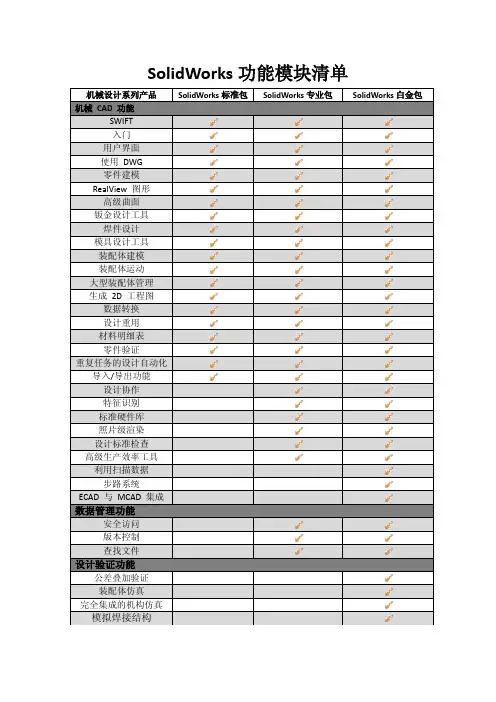
One solution tackles all your design challengesSolidWorks ® Premium 2011 improves productivity and innovation with ease of use, powerful functionality, and world-class support in one package. Cut design time, improve collaboration across your entire team, and reduce manufacturing costs.Move quickly from idea to realityAdvance your idea from concept to market quickly using a rich 3D model as a foundation of the process.• Part and assembly modeling – SolidWorks Premium enables you to designthe most advanced products• 3D solid modeling – create 3D parts with complex geometries, assemblies, and associated drawings; drawings automatically update with part and assembly changes, to keep all your design data up to date• Large assembly design capabilities – create and manage extremely large designs and work in either detailed or simplified modes• Advanced surfacing – create and edit complex solid and surface geometry, including stylish, curve-continuous (C2) surfaces, using “push-pull” control points on the geometry • Sheet metal – design from scratch or convert your 3D part to sheet metal— flatten your design and document for manufacturing• Weldments – quickly design and fully document welded structures composed of structural members, plates, gussets, and other items• Mold design – design molded parts and the tooling to make them—including core and cavity, draft, parting surfaces, and mold base components • Piping/tubing design – generate and document 3D mechanicalsystems—including paths and a complete bill of materials (BOM)• Electrical cable/harness and conduit design – import electrical connectioninformation, generate and document 3D electrical route path, and complete theBOM in your designSOLIDWORKS PREMIUM 2011The complete 3D CAD solution for designing better productsSolidWorks Premium 2011 is the ultimate tool to design, validate, communicate, and manage your 3D CAD models. It provides a complete suite of design tools with efficient part, assembly, and drawing capabilities, as well as built-in simulation, routing, and image/animation creation tools. Together, this powerful suite makes the management of product data and the sharing of design ideas faster, simpler, and smarter.Rescue Equipment, Holmatro• Design reuse and automation – speed new designs by finding and reusing existing designs. Use SolidWorks design automation tools to speed the designprocess further• SolidWorks Search – enable users to search for any file—on their computer, network, SolidWorks PDM system, or Internet• Design automation – automate repetitive design tasks, including part, assembly, and drawing generation, using DriveWorksXpress• Configurations – automatically create multiple versions of parts and assemblies and save them in the same file for easy reference• Design Library – save frequently used parts, features, templates, and more in the Design Library for easy access• 3D models from suppliers – reduce design time by using 3D models and 2D data of catalog components from and other manufacturers • Smart Components and Smart Fasteners – reduce assembly creation time, using smart hardware that create their own holes or size to existing holes • Component Library – SolidWorks Toolbox provides millions of hardwarecomponents and other items to add to your assembly• Animations and photorealistic renderings – communicate your design intentwith great visuals that explain your idea correctly the first time• Photoview 360 – create photorealistic images and animations quickly, without being a graphics expert• Walk-through/fly-through animations – take a virtual walk through your design to explain it to others and record a video• Assembly animation – demonstrate basic operation of your design by applying motion, gravity, and component contact or by manually moving components—and save a video of the demonstration• 2D drawings – expedite the creation of production-ready 2D drawings to clearlycommunicate how your design should be manufactured and assembled• Automatic Drawing View creation – simply drag and drop the 3D model into a drawing to create views with hidden lines, hidden lines removed, wire frame, or even shaded views. Include all types of views such as isometrics, sections,partial sections, and detailed views• Automated Drawing View updates – changes to the 3D part and assembly models are automatically reflected in the drawing views that are in synch with the 3D model• Dimensioning – automate the generation and placement of dimensions, including geometric dimensioning and tolerancing (GD&T) standards• Bill of Materials (BOM) – generate automated BOM and cut lists with balloons that update with model changes. Output BOM from an assembly or drawing for printing or upload to ERP/MRP systems• Annotations – create a complete drawing by adding all necessary tolerances, symbols, notes, hole call-outs, and tables• Standards checking – compare your drawings to company standards to ensure consistency with SolidWorks Design Checker• Drawing control – control drawing revisions and compare drawings graphically tounderstand their differencesSpeed machine design and simulation with built-in specialized functionality forcreating welded structures, production-quality drawings, and other tasks.Image courtesy of ABCO Automation, Inc.Ensure your idea will perform as designedVirtually test your design in a simulated real-world environment to reduce physical prototypes, save money, and complete your product faster.•Motion simulation– use SolidWorks Motion to help improve the kinematics of your design, leading to improved reliability•Structural validation–enhance product quality by identifying areas prone to failure and suggest changes to guide design optimization using tools built fordesigners and engineers who best know the design•Sustainability– use SolidWorks SustainabilityXpress to assess theenvironmental impact of your design and optimize material selection, partgeometry, and sourcing•Fluid flow simulation–use FloXpress to provide initial fluid flow simulation and reportingEnsure your design can be manufactured correctly the first timeUse SolidWorks Premium tools to verify your design can be efficiently produced before it reaches manufacturing, significantly reducing waste.•Collision and interference detection–check for proper relationships between the components in your design to ensure proper operation•Hole alignment checks in assembly design–eliminate misalignments between components prior to manufacturing•Tolerance stack-up analysis–use TolAnalyst to check the effect of tolerances on parts and assemblies•Design for manufacturing–use DFMXpress to assess the manufacturabilityprior to production release•Output 2D manufacturing data–send 2-axis DXF and DWG file informationdirectly to production•Sheet metal flat pattern – automatically flatten sheet metal parts, includingbend compensation•Draft and undercut analysis – streamline plastic/cast/forged part and tooling design to eliminate problems before manufacturing•3D for rapid prototyping – SolidWorks directly outputs STL and other fileformats to rapid prototype equipment•3D CAM output – integration with the world’s leading CAM packages.SolidWorks Certified Gold Solution Partner CAM products are fully integratedinside SolidWorks for maximum design efficiency•Automatic output of hole charts, weld tables, cut lists, and CNC pipe bending data – streamlines production preparation•Harness-board drawings–generate drawings and wire cut lists for electricalmanufacturingCollaborate and communicate your ideas efficientlyShare CAD data and collaborate with others on product design quickly and easily.•Import/export – convert CAD data into any format your audience needs•Existing 2D DWG data– maintain these designs using SolidWorks 2D CAD tools Built-in tools speed the design and documentation of extremely large assemblies.Image courtesy of Bucyrus International Inc.Dassault Systèmes SolidWorks Corp. 300 Baker AvenueConcord, MA 01742 USA Phone:180****9000Outside the US: +1 978 371 5011 Email:*******************• Feature Recognition – automatically convert non-SolidWorks CAD data to preserve design intent and make future design changes faster • Protect your IP – use Defeature technology to hide selected aspects of your design prior to sharing models• Import scanned data – use ScanTo3D to convert scanned data to SolidWorksgeometry to facilitate reverse engineering• ECAD-MCAD data exchange – use CircuitWorks TM to provide two-way data exchange to reduce design errors in electronic packaging design• eDrawings ® – a compact, email-friendly file and viewing technology that letsyou review your 2D drawing and 3D model data together. eDrawings supports viewing SolidWorks, DWG, and numerous CAD formats and enables the extendedteam to review the design, including rotate, zoom, measure, mark-up, section, andvirtual disassembly• SolidWorks product data management (PDM) – provides revision control,data security, and access control to components for use in new designs. Alsofinds existing designs so they can be reused in other productsLearn fast, work fastSolidWorks Premium combines ease-of-use features with the broadest range of support options in the CAD industry, ensuring both occasional and full-time users can become productive quickly.• Easy, heads-up user interface – SolidWorks intuitive interface anticipatesyour next move which speeds the design process. Context-sensitive commands, mouse gestures, command manager toolbar, and direct geometry editing using Instant3D maximize productivity• Intelligent modeling – SolidWorks Intelligent Feature Technology (SWIFT)improves user productivity by automatically detecting and resolving modeling challenges that would typically frustrate new users• Learning resources – SolidWorks offers a broad range of tools for learningand support. Tutorials, online help, blogs, forums, the SolidWorks local user group (SWUG) community, and an extensive reseller network provide assistance to allusersVisit /premium or contact your local authorized SolidWorks reseller to learn more.Data exchange:SolidWorks Premium 2011 featuresbuilt-in translators that let you exchange CAD data created in a wide variety of software applications and file formats, including:• PDF • STEP • IGES • DWG • DXF• Parasolid ®• Pro/ENGINEER ®• IAM (Autodesk Inventor ®)• IPT (Autodesk Inventor)• Mechanical Desktop ®• Unigraphics ®• PAR (Solid Edge ®)• CADKEY ®• Rhino • IDF • IFC• SAT (ACIS ®)• VDA-FS • VRML • STL• U3D (Universal 3D)• TIFF • JPG• AI (Adobe ® Illustrator ®)• PSD (Adobe Photoshop ®)• 3D XML• CGR (CATIA ® graphics)• HCG (CATIA highly compressed graphics)• HSF (Hoops)Supported standards:• ANSI • GOST • BSI • ISO • DIN • JIS• GBRecommended system requirements:Please visit:/systemrequirements。