交通工程毕业设计翻译
- 格式:doc
- 大小:258.00 KB
- 文档页数:7
土木工程专业毕业设计外文文献及翻译Here are two examples of foreign literature related to graduation design in the field of civil engineering, along with their Chinese translations:1. Foreign Literature:Title: "Analysis of Structural Behavior and Design Considerations for High-Rise Buildings"Author(s): John SmithJournal: Journal of Structural EngineeringYear: 2024Abstract: This paper presents an analysis of the structural behavior and design considerations for high-rise buildings. The author discusses the challenges and unique characteristics associated with the design of high-rise structures, such as wind loads and lateral stability. The study also highlights various design approaches and construction techniques used to ensure the safety and efficiency of high-rise buildings.Chinese Translation:标题:《高层建筑的结构行为分析与设计考虑因素》期刊:结构工程学报年份:2024年2. Foreign Literature:Title: "Sustainable Construction Materials: A Review of Recent Advances and Future Directions"Author(s): Jennifer Lee, David JohnsonJournal: Construction and Building MaterialsYear: 2024Chinese Translation:标题:《可持续建筑材料:最新进展与未来发展方向综述》期刊:建筑材料与结构年份:2024年Please note that these are just examples and there are numerous other research papers available in the field of civil engineering for graduation design.。
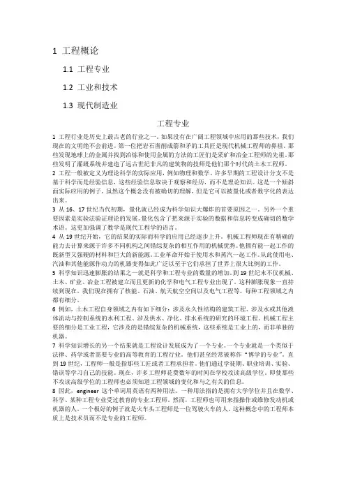
1 工程概论1.1 工程专业1.2 工业和技术1.3 现代制造业工程专业1 工程行业是历史上最古老的行业之一。
如果没有在广阔工程领域中应用的那些技术,我们现在的文明绝不会前进。
第一位把岩石凿削成箭和矛的工具匠是现代机械工程师的鼻祖。
那些发现地球上的金属并找到冶炼和使用金属的方法的工匠们是采矿和冶金工程师的先祖。
那些发明了灌溉系统并建造了远古世纪非凡的建筑物的技师是他们那个时代的土木工程师。
2 工程一般被定义为理论科学的实际应用,例如物理和数学。
许多早期的工程设计分支不是基于科学而是经验信息,这些经验信息取决于观察和经历,而不是理论知识。
这是一个倾斜面实际应用的例子,虽然这个概念没有被确切的理解,但是它可以被量化或者数字化的表达出来。
3 从16、17世纪当代初期,量化就已经成为科学知识大爆炸的首要原因之一。
另外一个重要因素是实验法验证理论的发展。
量化包含了把来源于实验的数据和信息转变成确切的数学术语。
这更加强调了数学是现代工程学的语言。
4 从19世纪开始,它的结果的实际而科学的应用已经逐步上升。
机械工程师现在有精确的能力去计算来源于许多不同机构之间错综复杂的相互作用的机械优势。
他拥有能一起工作的既新型又强硬的材料和巨大的新能源。
工业革命开始于使用水和蒸汽一起工作。
从此使用电、汽油和其他能源作动力的机器变得如此广泛以至于它们承担了世界上很大比例的工作。
5 科学知识迅速膨胀的结果之一就是科学和工程专业的数量的增加。
到19世纪末不仅机械、土木、矿业、冶金工程被建立而且更新的化学和电气工程专业出现了。
这种膨胀现象一直持续到现在。
我们现在拥有了核能、石油、航天航空空间以及电气工程等。
每种工程领域之内都有细分。
6 例如,土木工程自身领域之内有如下细分:涉及永久性结构的建筑工程、涉及水或其他液体流动与控制系统的水利工程、涉及供水、净化、排水系统的研究的环境工程。
机械工程主要的细分是工业工程,它涉及的是错综复杂的机械系统,这些系统是工业上的,而非单独的机器。
本科毕业设计(论文)外文翻译基本规范一、要求1、与毕业论文分开单独成文。
2、两篇文献。
二、基本格式1、文献应以英、美等国家公开发表的文献为主(Journals from English speaking countries)。
2、毕业论文翻译是相对独立的,其中应该包括题目、作者(可以不翻译)、译文的出处(杂志的名称)(5号宋体、写在文稿左上角)、关键词、摘要、前言、正文、总结等几个部分。
3、文献翻译的字体、字号、序号等应与毕业论文格式要求完全一致。
4、文中所有的图表、致谢及参考文献均可以略去,但在文献翻译的末页标注:图表、致谢及参考文献已略去(见原文)。
(空一行,字体同正文)5、原文中出现的专用名词及人名、地名、参考文献可不翻译,并同原文一样在正文中标明出处。
二、毕业论文(设计)外文翻译(一)毕业论文(设计)外文翻译的内容要求外文翻译内容必须与所选课题相关,外文原文不少于6000个印刷符号。
译文末尾要用外文注明外文原文出处。
原文出处:期刊类文献书写方法:[序号]作者(不超过3人,多者用等或et al表示).题(篇)名[J].刊名(版本),出版年,卷次(期次):起止页次.原文出处:图书类文献书写方法:[序号]作者.书名[M].版本.出版地:出版者,出版年.起止页次.原文出处:论文集类文献书写方法:[序号]作者.篇名[A].编著者.论文集名[C]. 出版地:出版者,出版年.起止页次。
要求有外文原文复印件。
(二)毕业论文(设计)外文翻译的撰写与装订的格式规范第一部分:封面1.封面格式:见“毕业论文(设计)外文翻译封面”。
普通A4纸打印即可。
第二部分:外文翻译主题1.标题一级标题,三号字,宋体,顶格,加粗二级标题,四号字,宋体,顶格,加粗三级标题,小四号字,宋体,顶格,加粗2.正文小四号字,宋体。
第三部分:版面要求论文开本大小:210mm×297mm(A4纸)版芯要求:左边距:25mm,右边距:25mm,上边距:30mm,下边距:25mm,页眉边距:23mm,页脚边距:18mm字符间距:标准行距:1.25倍页眉页角:页眉的奇数页书写—浙江师范大学学士学位论文外文翻译。

南京理工大学紫金学院毕业设计(论文)外文资料翻译系:机械系专业:车辆工程专业姓名:宋磊春学号:070102234外文出处:EDU_E_CAT_VBA_FF_V5R9(用外文写)附件:1。
外文资料翻译译文;2.外文原文.附件1:外文资料翻译译文CATIA V5 的自动化CATIA V5的自动化和脚本:在NT 和Unix上:脚本允许你用宏指令以非常简单的方式计划CATIA。
CATIA 使用在MS –VBScript中(V5.x中在NT和UNIX3。
0 )的共用部分来使得在两个平台上运行相同的宏。
在NT 平台上:自动化允许CATIA像Word/Excel或者Visual Basic程序那样与其他外用分享目标。
ATIA 能使用Word/Excel对象就像Word/Excel能使用CATIA 对象。
在Unix 平台上:CATIA将来的版本将允许从Java分享它的对象。
这将提供在Unix 和NT 之间的一个完美兼容。
CATIA V5 自动化:介绍(仅限NT)自动化允许在几个进程之间的联系:CATIA V5 在NT 上:接口COM:Visual Basic 脚本(对宏来说),Visual Basic 为应用(适合前:Word/Excel ),Visual Basic。
COM(零部件目标模型)是“微软“标准于几个应用程序之间的共享对象。
Automation 是一种“微软“技术,它使用一种解释环境中的COM对象。
ActiveX 组成部分是“微软“标准于几个应用程序之间的共享对象,即使在解释环境里。
OLE(对象的链接与嵌入)意思是资料可以在一个其他应用OLE的资料里连结并且可以被编辑的方法(在适当的位置编辑).在VBScript,VBA和Visual Basic之间的差别:Visual Basic(VB)是全部的版本。
它能产生独立的计划,它也能建立ActiveX 和服务器。
它可以被编辑。
VB中提供了一个补充文件名为“在线丛书“(VB的5。

毕业设计(论文)外文翻译题目西北物流中心2号楼设计专业土木工程班级土木074学生指导教师二零一零年Low-coherence deformation sensors for themonitoring of civil-engineering structuresD. Inaudi a, A. Elamari b, L. Pflug a, N. Gisin b, J. Breguet b, S. Vurpillot a “IMAC, Laboratory of Stress Analysis, Swiss Federal Institute of Technology, CH-1015 Lausanne, Switzerland ‘GAP, Group of Applied Physics -Optical Seciion, Geneva University CH-1205 Geneva, SwitzerlandRcccivcd 25 January 1993; in revised form 8 March 1994; accepted 25 March 1994 AbstractAn optical-fiber deformation sensor with a resolution of 10 pm and an operational range of 60 mm has been realized. The system is based on low-coherence interferometry instandard single-mode telecommunication fibers. It allows the monitoring of large structures over several months without noticeable drift. No continuous measurement is needed and the system is insensitive to variations of the fiber losses. This technique has been applied to the monitoring of a 20 m X5 m X0.5 m, 120 ton concrete slab over six months. It is possible to measure the shrinkage of concrete and its elastic coefficient during pre-straining, giving reproducible results in good agreement with theoretical calculations and measurements performed on small concrete samples. This paper describes the optical arrangement and the procedures used to install optical fibers in concrete.Keywor&: Ikformation sensors; Civil-engineering structures1. IntroductionBoth the security of civil-engineering works and the law require a periodic monitoring of structures. The methods used for this purpose, such as triangulation, water levels or vibrating strings, are often of tedious application and require one or many specialized operators. This complexity and the resulting costs limit the frequency of the measurements. Furthermore, the spatial resolution is often poor and the observation is usually restricted to the surface of the object. There is thus a real demand for a tool allowing an internal, automatic and permanent monitoring of structures with high accuracy and stability over periods typically of the order of 100 years for bridges. In this framework, fiber-optic smart structures (i.e., structures with self-testing capabilities) are gaining in importance in many fields including aeronautics and composite material monitoring. This technology can be applied in civilengineering and in particular for the short- and long-time observation of large structures such as bridges, tall building frames, dams, tunnels, roads, airport runways, domes, pre-stressing and anchorage cables. The monitoring of such structures requires the development of a measuring technique with high accuracy,stability and reliability over long periods. It has to beindependent of variations in the fiber losses and adapted to the adverse environment of a building site. To reduce the cost of the instrumentation, it is furthermore desirable to use the same portable reading unit for the monitoring of multiple structures. We describe here asystem based on low-coherence interferometry responding to all these requirements.2. Experimental arrangementThe measuring technique relies on an array of standard telecommunication optical fibers in mechanical contact with concrete. Any deformation of the host structure results jn a change in the optical length of he fibers. Each sensor line consists of two single-mode ibers: one measurement fiber in mechanical contact with the structure (glued or cemented) and a reference iber placed loose near the first one (in a pipe) in order to be at the same temperature. Since the measurement technique monitors the length difference beween these two fibers, only the mechanical deformation will have an effect on the results while all other perurbations, such as thermally induced changes in the refractive index of the fibers,will affect the two in an identical way and cancel each another out. To measure the optical path difference between the two fibers, a low-coherence double interferometer in tandem configuration has been used (Fig. 1) [l]. The source is an LED (light-emitting diode) working around 1.3 pm with a coherence length L, of 30 pm and a rated power of 200 pW. The radiation is launched into a single-mode fiber and then directed toward the measurement and the reference fibers by means of a 50:50 single-mode directional coupler. At the ends of the fibers two mirrors reflect the light back to the coupler, where the beams arc recombined with a relative delay due to the length difference AL, between the fibers, and then directed towards the second (reference) interferometer. The reference interferometer is of Michelson type with one of the arms ended by a mobile mirror mounted on a micromctric displacement table with a resolution of 0.1 pm and an operating range of 50 mm. It allows the introduction of an exactly known path difFcrence AL, between its two arms. This fiber interferometer is portable and needs no optical adjustment after transportation. It has been developed by the GAP with the support of the Swiss PTT for optical cable testing [2].The intensity at the output of the reference inter- ferometer is measured with a pig-tail photodiode and is then given by [3]where zz,,r is the effective refractive index of the fiber, zzg the group refractive index (about 1% higher than nefr in silica), A, the central vacuum wavelength of the light, zi,, the autocorrelation function taking the spectral characteristics of the emission into account and AL the physical path difference between the two interfering paths. Further similar interference terms appear in Eq.(1) in the special cases when AL, <L, or AL, < L,. When the optical path difference between the arms in the reference interferometer corresponds to the one induced by the two fibers installed in the structure (within the coherence length of the source), interference fringes appear. Scanning AL, with the mirror of the reference interferometer it is possible to obtain AL = 0either with AL, = AL, or with AL, = -AL,, and thus two interference fringe packets as described by Eq. (1). The mirror position corresponding to AL, = 0 also produces an interference and is used as a reference. These three fringe packets arc detected by means of a lock-in amplifier synchronized with the mirror displacements. The mirror displacements and the digitalization of the lock-in output are carried out by means of a portable personal computer. Since the reference signal is gcnerated separately and does not have a constant phase relation to the interference signal, only the envelope of the demodulated signal has a physical meaning and corresponds to the envelope of the fringe pattern. A lock-in plot showing the three typical peaks is shown in Fig. 2. Each peak has a width of about 30 pm. The calculation of its center of gravity determines its position with a precision better than 10 pm. This precision is the limiting factor of the whole measurement technique. Since AL, is known with micrometer precision, it is possible to follow AL, with the same precision.Fig. 1. Experimental setup of the low-coherence double Michelson interferomctcr. D. Innudi et al. 1 Semors andFig. 2. Typical fringe cnvclope as a function of the mirror position. The distance between the central and the lateral peaks corresponds to the length difference between the measurement and the reference fibers mounted in the table. Any change in the length of the structure results in a change in the position of these peaks. Any change in the losses of the fibers will result in a change of the height of the peaks. The central peak is fixed and used as a reference.The path difference AL, is proportional to the de-formation of the structure AL, with the relation between the two given by [4]where p is Poisson’s ratio and pij is the strain optic tensor (Pockcl’s coefhcients). The coefficient 5 takes into account the variation of the effective index neff in a fiber under strain.A degradation of one or both fibers (due to aging, for example) will result in a lower visibilityof the fringes but will not affect its position. The information about the deformation of the structure is encoded in the coherence properties of light and not in its intensity as in the majority of the sensors applied to date in civil-engineering structures, mostly based on microbend losses and/or optical time-domain reflectometry (OTDR) techniques. Interference peaks resulting from reflections as low as -30 dB of the source power can be detected by our system without phase modulators. By modulating the phase in one of the four arms of the two interferometers, one can increase the dynamic range of the device to more than 100 dB [5].Even if the polarization dispersion and bend-induced birefringence in the sensing fibers could reduce the visibility of the interference fringes or even split the fringe packets, none of those effects was observed in our experiment. No adjustment of polarization between the reference and the sensing arm was then necessary. A good mechanical contact between the measurement fiber and the structure under test is fundamental. In this study a number of installation procedures have been tested and optimized for the different measurements (shrinkage, elasticity modulus, etc.). The mounting techniques can be divided into two main categories: full-length coupling and local coupling.During our tests five out of six optical fiber pairs with a 0.9 mm nylon coating, being mounted on the external face of a 20 m long plastic pipe and protected only with thin rubber bands (see Fig. 3(a)), survived the concreting process. During the setting process the concrete envelops the fiber and realizes the desired mechanical contact. Those fibers showed a minor increase in the scattering losses and the appearance of small parasite peaks. The measurements on those fibers were consistent with the results obtained with other installation techniques (see below). It seems that for full-length coupling the nylon coating transmits the structure deformations (extension and shortening) entirely to the fiber core. This installation technique is very promising when compared to the usual procedure, consisting of a pipe protecting the fibers during the pouring of concrete and being removed before the setting process begins. This second method seemsmore adapted to small samples than to full-scale structures. Eleven otherfiber pairs were glued at the two ends of the table after removing locally the protective coating layers of the fibers (see Fig. 3(b)). The silica fiber was ftxed with epoxy glue to a metallic plate mounted on the end facesof the concrete structure. The gluing length was about 20 mm. Apre-strain (between 0.1 and 0.4%) has been given to those fibers during the gluing process to keep them under tension and allow the measurement of both expansion and shrinkage of the structure. This type of local coupling proved to be the most reliable, but was not adapted to following thedeformation during the pre-stressing of the table because of the important surface deformations occurring during this operation. The problem has been overcome by gluing other fibers inside the pipes at about two meters from the surfaces, i.e., far from the force insertion region (see Fig. 3(c)).Fig. 3. Schematic representation of three of the installation techniques used:(a) direct concreting of the measurement fiber mounted on a plastic pipe; (b) fiber glued at the table surface; (c) fiber glued inside the pipe at 2m from the pipe ends.Fig. 4. Top and side views of the concrete table measured in the experiment and position of the sensing-fiber pairs A, B, C and D. Fibers A, B and C arc glued at the surface of the structure, while fiber D is glued inside a pipe, 2 m away from the surface of the slab. Twelve more fihcr pairs were installed, but are not shown for simplicity.To study the possible effect of creep in strained fibers [6], one fiber has been mounted on a mechanical support that allows the fiber to be tightened only at the time of the measurement. No difference between this fiberand those permanently strained has been observed over a period of six months, confirming the assumption that no creep occurs for fiber strains below 1%. Since the scanning range of the mirror is 5 mm, it was easy to cleave the 20 m long fibers within this margin. The Fresnel reflection of the cleaved fibers combined with the high dynamic of the system allow a measurement of AL,,. This value of AL, can than be used to correct the cutting and obtain pairs with length differences below 1 mm. Two ferrules were then installed on the fiber ends and mounted in front of a polished inox surface. Chemical silver deposition was also used to produce mirrors on the cleaved fiber ends.Fig. 6. Comparison between the measurements performed on the structure by optical fibers and the ones performed on 360 mm and 500 mm samples in a mechanical micrometer comparator. The measurement on the samples was possible only during the first two months.3. ResultsSeveral long- and short-term measurements have been carried on a 20 m x 5 m x 0.5 m, 120 ton concrete slab intended to be used as a vibration-isolated base for optical analysis (in particular by holographic and speckle interferometry) of large structures [7].This structure has been concreted indoors, allowing controlled environmcntal conditions and known concrete composition to be achieved. Samples have been prepared with the same material composition and are under permanent test for their mechanical properties (resistance, shrinkage and elastic coefficient). This allows a direct comparison between the results on the full-scale structure and the samples. The table has been pre-strained 23 days after concreting in both length and width. It was possible at this time to measure the elastic coefficient of the material in full scale. Fig. 4 shows a schematic representation of the table and the position of the fibers referred to in the experimental results. At the time of writing, the table has been under test for six months. Over this period the shrinkage in the longitudinal direction (i.e., over 20 m) has been about 6 mm. We show in Fig. 5 the results of the measurements for three (glued) fibers over 175 days. The table has a T profile (Fig. 4). It is evident from Fig. 5 that thefibers mounted near the borders of the table, i.e., were the thickness is smaller, registered a larger shrinkage, as expected according to the concrete theory. Adjacentfibers give consistent results independently of the installation technique. No difference has been noticed between the fibers under permanent tension and those loosened between the measurements, suggesting that no creep of glass fibers occurred. The shrinkage measured with the fiber system has been compared during the first two months with the results obtained with a mechanical comparator mounted on two samples of 360 mm and 500 mm, respectively.The observed deformations have been scaled to 20m and are compared in Fig.6 to the results obtained with fibers B and C. Very good agreement is found between the two measurements. A theoretical comparison between the experimentalresults and the Swiss civil engineering standards has also been carried out. The experimental data and the standards are in agreement within f 10%. A more accurate simulation including the physico-chemical properties of the concrete used is under development. The table was pre-stressed 23 days after concreting. The five steel cables running over the length of the table and the forty cables running over its width were stretched with a force of 185 kN (18.5 Tons) each. The fibers glued to the surface and those in direct contact with concrete over the whole length measured an expansion of the table instead of the expected shrinkage. This is due to the important surface deformations occurring near the force-insertion points, i.e., near the pre-stress heads that were placed near the fiber ends. Fiber D glued inside the plastic pipe at 2m from each endwas not subject to these local effects and measured a shortening of 0.23 mm. The theoretical calculation based on an elastic coefficient of 30 kN/mm2gives a shortening of 0.28mm at the borders and 0.19 mm at the center of the table. Since fiber D was placed in an intermediate position, the experimental value can be considered to be in good agreement with the theory.4. ConclusionsA new deformation sensor adapted to the monitoring of civil-engineering structures has been proposed. it is based on low-coherence interferometry in standard lowcost telecommunication fibers. The resolution of the measurements is 10 pm, the operational range is 60mm and the stability has been tested over six months without noticeable drift. The reading unit is compact and portable, needing no optical alignment before the measurements. It is controlled by a portable personal computer, which is also responsible for the data trcatment. The same reading unit can be used to monitor multiple fiber lines by simple manual unplugging. This technique is furthermore practically insensitive to increased losses due to degradation of the fibers. A test study has been carried out on a 20m ~5m X 0.5m concrete slab, giving consistent results when compared to other measurement techniques based on samples or to concrete theories. It was possible to follow concrete shrinkage over six months (the cxper- iment will continue for about five years) and to measure the elastic coefficient on the full-scale structure. Different fiber-installation techniques adapted to the measurement of various parameters have been tested in building-site conditions. This technique appears very promising for the mon-itoring of civil-engineering structures such as bridges, dams and tunnels, allowing internal, automatic and permanent monitoring with high precision and stability over long periods.AcknowledgmentsThe authors are indebted to R. Passy and R. Delez for their assistance, encouragement and helpful dis-cussion. We acknowledge the IMM Institute in Lugano (Switzerland) for placing the table at our disposal and for the measurements carried out on concrete samples. We are grateful to Dr M. Pedretti and Ing R. Passera for their personal engagement in the project. We also thank Cabloptic in Cortaillod (Switzerland) for sup-plying all the optical fibers used in the experiment. This research has been performed with the financial support of CERS (Commission pour 1’Encouragement de la Recherche Scientifique).References[1] A.Koch and R.Ulrich,Fiber optic displacement sensor with 0.02mm resolutionbuy white-light interferometry,sensors and actuators A,25-27(1991)201-207[2]N.Gisin,J.-P.Von der weid and J.-P.Pellaux,Polarization mode dispersion ofshort and long single-mode fibers,J.Lightwave technol,9(1991)821-827.[3] A.S.Gergcs,F.Farahi,T.P.Newson,J.D.C.Jones and D.A.Jackson, Fiber-opticinterferometric sensors using low coherence source:dynamic range enhancement,Int. J.Op-toelectron,3(1988)311-322.[4] C.D.Butter and G.B.Hacker, Fiber optics strain gauge,Appl.Opt,17(1978)2867-2869.[5]H.H.Gilger,G.Bodmer and Ch.Zimmer, Optical coherance domain retlectometry asa test method of integrated optics devices,Proc.2nd Opt. Fibre Meas. Conf:OFMC 93, Turin, Ztuly, Z993, pp.143-146.[6]J.-P.Jaguin and A.Zaganiaris,La mecanique de rupture appliquee aux fibresoptiques, Verres Refract, 34 (Jul-Aout)(1980).[7]L.Pflug and M.Pedretti, Construction of a loo-tonnes holographictable,ZS&TISPIE Znt.Symp. Electronic Imaging, SanJose,CA,USA,1993,pp.50-54.传感器和执行器 A 44(1994)12.5-130用低变形传感器监测民用工程结构变形的一致性D.Inaudi a, A.Elamari b, L.Pflug b, N.Gisin b, J.Breguet b, S.Vurpillot aa IMAC、实验室的应力分析,瑞士联邦理工学院,CH-1015瑞士洛桑b GAP,群应用物理-光学部分,日内瓦大学,CH-1205瑞士日内瓦举行1993年1月25日实验;1994年3月8日修订,1994年3月25日发表文摘一个光纤变形的分辨率的传感器,10µm和运行范围的60毫米已经实现了。

AT89C51外文翻译DescriptionThe AT89C51 is a low-power, high-performance CMOS 8-bit microcomputer with 4K bytes of Flash Programmable and Erasable Read Only Memory (PEROM). The device is manufactured using Atmel’s high density nonvolatile memory technology and is compatible with the industry standard MCS-51™ instruction-set and pinout. The on-chip Flash allows the program memory to be reprogrammed in-system or by a conventional nonvolatile memory programmer. By combining a versatile 8-bit CPU with Flash on a monolithic chip, the Atmel A T89C51 is a powerful microcomputer which provides a highly flexible and cost effective solution to many embedded control applications.Features• Compatible with MCS-51™ Products• 4K Bytes of In-System Reprogrammable Flash Memory– Endurance: 1,000 Write/Erase Cycles• Fully Static Operation: 0 Hz to 24 MHz• Three-Level Program Memory Lock• 128 x 8-Bit Internal RAM• 32 Programmable I/O Lines• Two 16-Bit Timer/Counters• Six Interrupt Sources• Programmable Serial Channel• Low Power Idle and Power Down ModesThe AT89C51 provides the following standard features: 4K bytes of Flash,128 bytes of RAM, 32 I/O lines, two 16-bit timer/counters, a five vector two-level interrupt architecture, a full duplex serial port, on-chip oscillator and clock circuitry. In addition, the AT89C51 is designed with static logic for operation down to zero frequency and supports two software selectable power saving modes. The Idle Mode stops the CPU while allowing the RAM, timer/counters, serial port and interrupt system to continue functioning. The Power-down Mode saves the RAM contents but freezes the oscillator disabling all other chip functions until the next hardware reset.VCCSupply voltage.GNDGround.Port 0Port 0 is an 8-bit open-drain bi-directional I/O port. As an output port, each pin can sink eight TTL inputs. When 1s are written to port 0 pins, the pins can be used as high-impedance inputs.Port 0 may also be configured to be the multiplexed low-order address/data bus during accesses to external program and data memory. In this mode P0 has internal pullups. Port 0 also receives the code bytes during Flash programming, and outputs the code bytes during program verification. External pullups are required during program verification.Port 1Port 1 is an 8-bit bi-directional I/O port with internal pullups.The Port 1 output buffers can sink/source four TTL inputs.When 1s are written to Port 1 pins they are pulled high by the internal pullups and can be used as inputs. As inputs,Port 1 p ins that are externally being pulled low will source current (IIL) because of the internal pullups.Port 1 also receives the low-order address bytes during Flash programming and verification.Port 2Port 2 is an 8-bit bi-directional I/O port with internal pullups.The Port 2 output buffers can sink/source four TTL inputs.When 1s are written to Port 2 pins they are pulled high by the internal pullups and can be used as inputs. As inputs,Port 2 pins that are externally being pulled low will source current (IIL) because of the internal pullups. Port 2 emits the high-order address byte during fetches from external program memory and during accesses to external data memory that use 16-bit addresses (MOVX @DPTR). In this application, it uses strong internal pullups when emitting 1s. During accesses to external data memory that use 8-bit addresses (MOVX @ RI), Port 2 emits the contents of the P2 Special Function Register. Port 2 also receives the high-order address bits and some control signals during Flash programming and verification.Port 3Port 3 is an 8-bit bi-directional I/O port with internal pullups. The Port 3 output buffers can sink/source four TTL inputs.When 1s are written to Port 3 pins they arepulled high by the internal pullups and can be used as inputs. As inputs,Port 3 pins that are externally being pulled low will source current (IIL) because of the pullups. Port 3 also serves the functions of various special features of the AT89C51 as listed below:Port 3 also receives some control signals for Flash programming and verification. RSTReset input. A high on this pin for two machine cycles while the oscillator is running resets the device.ALE/PROGAddress Latch Enable output pulse for latching the low byte of the address during accesses to external memory. This pin is also the program pulse input (PROG) during Flash programming. In normal operation ALE is emitted at a constant rate of 1/6 the oscillator frequency, and may be used for external timing or clocking purposes. Note, however, that one ALE pulse is skipped during each access to external Data Memory.If desired, ALE operation can be disabled by setting bit 0 of SFR location 8EH. With the bit set, ALE is active only during a MOVX or MOVC instruction. Otherwise, the pin is weakly pulled high. Setting the ALE-disable bit has no effect if the microcontroller is in external execution mode.PSENProgram Store Enable is the read strobe to external program memory. When the AT89C51 is executing code from external program memory, PSEN is activated twice each machine cycle, except that two PSEN activations are skipped during each access to external data memory.EA/VPPExternal Access Enable. EA must be strapped to GND in order to enable the device to fetch code from external program memory locations starting at 0000H up toFFFFH.Note, however, that if lock bit 1 is programmed, EA will be internally latched on reset. EA should be strapped to VCC for internal program executions.This pin also receives the 12-volt programming enable voltage (VPP) during Flash programming, for parts that require 12-volt VPP.XTAL1Input to the inverting oscillator amplifier and input to the internal clock operating circuit.XTAL2Output from the inverting oscillator amplifier.Oscillator CharacteristicsXTAL1 and XTAL2 are the input and output, respectively,of an inverting amplifier which can be configured for use as an on-chip oscillator, as shown in Figure 1. Either a quartz crystal or ceramic resonator may be used. To drive the device from an external clock source, XTAL2 should be left unconnected while XTAL1 is driven as shown in Figure 2.There are no requirements on the duty cycle of the external clock signal, since the input to the internal clocking circuitry is through a divide-by-two flip-flop, but minimum and maximum voltage high and low time specifications must be observed.Idle ModeIn idle mode, the CPU puts itself to sleep while all the on-chip peripherals remain active. The mode is invoked by software. The content of the on-chip RAM and all the special functions registers remain unchanged during this mode. The idle mode can be terminated by any enabled interrupt or by a hardware reset. It should be noted that when idle is terminated by a hard ware reset, the device normally resumes program execution, from where it left off, up to two machine cycles before the internal reset algorithm takes control. On-chip hardware inhibits access to internal RAM in this event, but access to the port pins is not inhibited. To eliminate the possibility of an unexpected write to a port pin when Idle is terminated by reset, the instruction following the one that invokes Idle should not be one that writes to a port pin or to external memory.Figure 1. Oscillator ConnectionsNote: C1, C2 = 30 pF ± 10 pF for Crystals= 40 pF ± 10 pF for Ceramic ResonatorsFigure 2. External Clock Drive ConfigurationPower-down ModeIn the power-down mode, the oscillator is stopped, and the instruction that invokes power-down is the last instruction executed. The on-chip RAM and Special Function Registers retain their values until the power-down mode is terminated. The only exit from power-down is a hardware reset. Reset redefines the SFRs but does not change the on-chip RAM. The reset should not be activated before VCC is restored to its normal operating level and must be held active long enough to allow the oscillator to restart and stabilize.Program Memory Lock BitsOn the chip are three lock bits which can be left unprogrammed (U) or can be programmed (P) to obtain the additional features listed in the table below.When lock bit 1 is programmed, the logic level at the EA pin is sampled and latched during reset.If the device is powered up without a reset, the latch initializes to a random value, and holds that value until reset is activated. It is necessary that the latched value of EA be in agreement with the current logic level at that pin in order for the device to function properly.Programming the FlashThe AT89C51 is normally shipped with the on-chip Flash memory array in the erased state (that is, contents = FFH)and ready to be programmed. The programming interface accepts either a high-voltage (12-volt) or a low-voltage (VCC) program enable signal. The low-voltage programming mode provides a convenient way to program the AT89C51 inside t he user’s system, while the high-voltage programming mode is compatible with conventional thirdparty Flash or EPROM programmers.The AT89C51 is shipped with either the high-voltage or low-voltage programming mode enabled. The respective top-side marking and device signature codes are listed in the following table.The AT89C51 code memory array is programmed byte-by-byte in either programming mode. To program any non-blank byte in the on-chip Flash Memory, the entire memory must be erased using the Chip Erase Mode. Programming Algorithm: Before programming the A T89C51, the address, data and control signals should be set up according to the Flash programming mode table and Figures 3 and 4. To program the AT89C51, take the following steps.1. Input the desired memory location on the address lines.2. Input the appropriate data byte on the data lines.3. Activate the correct combination of control signals.4. Raise EA/VPP to 12V for the high-voltage programming mode.5. Pulse ALE/PROG once to program a byte in the Flash array or the lock bits. The byte-write cycle is self-timedand typically takes no more than 1.5 ms. Repeat steps 1 through 5, changing the address and data for the entire array or until the end of the object file is reached.Data Polling: The AT89C51 features Data Polling to indicate the end of a write cycle. During a write cycle, anattempted read of the last byte written will result in the complement of the written datum on PO.7. Once the write cycle has been completed, true data are valid on all outputs, and the next cycle may begin. Data Polling may begin any time after a write cycle has been initiated.Ready/Busy: The progress of byte programming can also be monitored by the RDY/BSY output signal. P3.4 is pulled low after ALE goes high during programming to indicate BUSY. P3.4 is pulled high again when programming is done to indicate READY.Program V erify: If lock bits LB1 and LB2 have not been programmed, the programmed code data can be read back via the address and data lines for verificatio n. The lock bits cannot be verified directly. V erification of the lock bits is achieved by observing that their features are enabled.Chip Erase: The entire Flash array is erased electrically by using the proper combination of control signals and by holding ALE/PROG low for 10 ms. The code array is written with all ―1‖s. The chip erase operation must be executed before the code memory can be re-programmed.Reading the Signature Bytes: The signature bytes are read by the same procedure as a normal verification of locations 030H, 031H, and 032H, except that P3.6 and P3.7 must be pulled to a logic low. The values returned are as follows.(030H) = 1EH indicates manufactured by Atmel(031H) = 51H indicates 89C51(032H) = FFH indicates 12V programming(032H) = 05H indicates 5V programmingProgramming InterfaceEvery code byte in the Flash array can be written and the entire array can be erased by using the appropriate combination of control signals. The write operation cycle is selftimed and once initiated, will automatically time itself to completion.All major programming vendors offer worldwide support for the Atmelmicrocontroller series. Please contact your local programming vendor for the appropriate software revision.Flash Programming and V erification Waveforms - High-voltage Mode (VPP = 12V)Flash Programming and V erification Waveforms - Low-voltage Mode (VPP = 5V)Flash Programming and Verification Characteristics TA = 0°C to 70°C, VCC = 5.0 ±10%Absolute Maximum Ratings**NOTICE: Str esses beyond those listed under ―Absolute Maximum Ratings‖ may cause permanent damage to the device. This is a stress rating only and functional operation of the device at these or any other conditions beyond those indicated in the operational sections of this specification is not implied. Exposure to absolute maximum rating conditions for extended periods may affect device reliability.DC CharacteristicsTA = -40°C to 85°C, VCC = 5.0V ±20% (unless otherwise noted)Notes: 1. Under steady state (non-transient) conditions, IOL must be externally limited as follows:Maximum IOL per port pin: 10 mAMaximum IOL per 8-bit port: Port 0: 26 mAPorts 1, 2, 3: 15 mAMaximum total IOL for all output pins: 71 mAIf IOL exceeds the test condition, VOL may exceed the related specification. Pins arenot guaranteed to sink current greater than the listed test conditions.2. Minimum VCC for Power-down is 2V.AC CharacteristicsUnder operating conditions, load capacitance for Port 0, ALE/PROG, and PSEN = 100 pF; load capacitance for all other outputs = 80 pF.External Program and Data Memory CharacteristicsExternal Program Memory Read CycleExternal Data Memory Read CycleExternal Data Memory Write CycleExternal Clock Drive WaveformsExternal Clock DriveSerial Port Timing: Shift Register Mode Test Conditions (VCC = 5.0 V ±20%; Load Capacitance = 80 pF)Shift Register Mode Timing WaveformsAC Testing Input/Output Waveforms(1)Note: 1. AC Inputs during testing are driven at VCC - 0.5V for a logic 1 and 0.45V for a logic 0. Timing measurements are made at VIH min. for a logic 1 and VIL max. for a logic 0.Float Waveforms(1)Note: 1. For timing purposes, a port pin is no longer floating when a 100mV change from load voltage occurs. A port pin begins to float when 100mV change from the loaded VOH/VOL level occurs.AT89C51中文原文AT89C51是美国ATMEL公司生产的低电压,高性能CMOS8位单片机,片内含4k bytes的可反复擦写的只读程序存储器(PEROM)和128 bytes的随机存取数据存储器(RAM),器件采用A TMEL公司的高密度、非易失性存储技术生产,兼容标准MCS-51指令系统,片内置通用8位中央处理器(CPU)和Flash存储单元,功能强大AT89C51单片机可为您提供许多高性价比的应用场合,可灵活应用于各种控制领域。

交通工程专业词汇中英术语对照中英术语对照公路highway道路road公路工程highway engineering公路网highway network公路网密度highway density公路等级highway classification公路自然区划climatic zoning for highway公路用地highway right-of-way高速公路freeway; expressway等级公路classified highway辅道relief road干线公路arterial highway支线公路feeder highway专用公路accommodation highway国家干线公路(国道)national trunk highway省级干线公路(国道)provincial trunk highway 县公路(县道)county road乡公路(乡道)township road辐射式公路radial highway环形公路ring highway绕行公路bypass交通结构traffic structure交通组成traffic composition混合交通mixed traffic交通流traffic flow交通流理论traffic flow theory车流vehicle stream交通密度traffic density车头间距space headway车头时距time headway车间净距vehicular gap延误delay地点速度spot speed行驶速度running speed运行速度operating speed临界速度critical speed平均速度average speed计算行车速度(设计车速)design speed交通量traffic volume年平均日交通量annual average daily traffic 月平均日交通量monthly average daily traffic 年第30位最大小时交通量thirtieth highest annualhourly volume年最大小时交通量maximum annual hourly 设计小时交通量design hourly volume通行能力traffic capacity基本通行能力basic traffic capacity可能通行能力possible traffic capacity设计通行能力design traffic capacity道路服务水平level of service公路交通规划traffic planning交通调查traffic survey交通量调查traffic volume survey交通量观测站traffic volume observation station起迄点调查(OD调查)origin-destination study 出行trip境内交通local traffic过境交通through traffic交通发生traffic generation交通分布traffic distribution交通分配traffic assignment交通预测traffic prognosis行车道carriageway分离式行车道divided carriageway 车道lane变速车道speed-change lane加速车道acceleration lane减速车道deceleration lane爬坡车道climbing lane停车道parking lane错车道turn-out lane自行车道cycle path路侧人行道sidewalk分隔带lane separator中央分隔带median divider中间带central strip路肩shoulder;verge路缘带marginal strip路缘石kerb;curb侧向余宽lateral clearance路拱camber;crown路拱横坡crown slope公路建筑限界clearance of highway 公路路线highway route公路线形highway alignment平面线形horizontal alignment纵面线形vertical alignment线形要素alignment elements平曲线horizontal curve极限最小平曲线半径limited minimum radius of horizontal curve复曲线compound curve反向曲线reverse curve断背曲线broken-back curve回头曲线switch-back curve缓和曲线transition curve竖曲线vertical curve弯道加宽curve widening加宽缓和段transition zone of curve超高superelevation超高缓和段superelevation runoff纵坡longitudinal gradient最大纵坡maximum longitudinal gradient最小纵坡minimum longitudinal gradient变坡点grade change point平均纵坡average gradiant坡长限制grade length limitation高原纵坡拆减highland grade compensation缓和坡段transition grading zone合成坡度resultant gradient视距sight distance停车视距non-passing sight distance, stopping sight distance 超车视距passing sight distance道路交叉road intersection;道口railroad grade crossing平面交叉at-grade intersection;grade crossing正交叉right-angle intersection斜交叉skew intersection环形交叉rotary intersection十字形交叉"+"T形交叉T intersection错位交叉offset intersection; staggered junctionY形交叉Y intersection立体交叉grade separation分离式立体交叉simple grade separation, separate grade crossing互通式立体交叉interchange苜蓿叶形立体交叉full cloverleaf interchange 部分苜蓿叶形立体交叉cloverleaf interchange 菱形立体交叉diamond interchange 定向式立体交叉directional interchange喇叭形立体交叉three-Leg interchange环形立体交叉rotary interchange匝道ramp 交叉口road crossing;intersection交叉口进口intersection entrance交叉口出口intersection exit加铺转角式交叉口intersection with widened corners拓宽路口式交叉口flared intersection分道转弯式交叉口channelized intersection渠化交通channelization交织weaving交织路段weaving section合流converging分流diverging冲突点conflict point交通岛traffic island导流岛channelization island中心岛central island安全岛refuge island沿线设施roadside facilities交通安全设施traffic safety device人行横道crosswalk人行地道pedestrian underpass人行天桥pedestrian overcrossing护栏guard fence防护栅guard fence,safety barrier遮光栅anti-dizzling screen应急电话emergency telephone反光标志reflective sign反光路钮reflective button弯道反光镜traffic mirror道路交通标志road traffic sign警告标志warning sign禁令标志regulatory sign指示标志guide sign指路标志information sign辅助标志auxiliary sign可变信息标志changeable message sign 路面标线pavement marking防雪设施snow protection facilities防沙设施sands protection facilities隔音墙acoustic barrier停车场parking area踏勘reconnaissance可行性研究feasibility study线形设计highway alignment design公路景观设计highway landscape design选线route selection路线控制点control point定线location比较线alternative line展线line development初测preliminary survey定测location survey地貌topographic feature地物culture地形topography台地terrace垭口pass;saddle back平原区plain terrain微丘区rolling terrain重丘区hilly terrain山岭区mountainous terrain沿溪线valley line山脊线ridge line山坡线hill-side line越岭线ridge crossing line土方调配cut-fill transition土方调配图cut-fill transition program土方调配经济运距economical hauling distance 导线traverse 导线测量traverse survey中线center line中线测量center line survey施工测量construction survey竣工测量final survey(路线)平面图plan交点intersection point虚交点imaginary intersection point转点turning point转角intersection angle方位角azimuth angle象限角bearing方向角direction angle切线长tangent length曲线长curve length外(矢)距external secant测站instrument station测点observation point中桩center stake加桩additional stake护桩reference stake断链broken chainage水准测量leveling survey水准点bench mark绝对基面absolute datum高程elevation 地面高程ground elevation设计高程designed elevation(路线)纵断面图profile中桩填挖高度cut and fill at center stake 地形测量topographic survey基线base line地形图topographic map等高线contour line横断面测量cross-sectional survey横断面图cross-section坑探pit test钻探boring摄影测量photogrammetry航空摄影测量aerial photogrammetry地面立体摄影测量ground stereophoto grammetry地面控制点测量ground control-point survey 航摄基线aerophoto base影像地图photographic map像片索引图(镶辑复照图)photo index航摄像片判读aerophoto interpretation综合法测图planimatric photo全能法测图universal photo微分法测图differential photo像片镶嵌图photo mosaic路基subgrade路堤embankment路堑cutting半填半挖式路基part cut-part fill subgrade 台口式路基benched subgrade路基宽度width of subgrade路基设计高程design elevation of subgrade (路基)最小填土高度minimum height of fill 边坡side slope边坡坡度grade of side slope(边)坡顶top of slope(边)坡脚toe of slope护坡道berm边坡平台plain stage of slope碎落台berm at the foot of cutting slope护坡slope protection挡土墙retaining wall重力式挡土墙gravity retaining wall衡重式挡土墙balance weight retaining wall 悬臂式挡土墙cantilever retaining wall扶壁式挡土墙counterfort retaining wall柱板式挡土墙column-plate retaining wall锚杆式挡土墙anchored retaining wall by tierods锚碇板式挡土墙anchored bulkhead retaining wall石笼rock filled gabion抛石riprap路基排水subgrade drainage边沟side ditch截水沟intercepting ditch排水沟drainage ditch急流槽chute跌水drop water蒸发池evaporation pond盲沟blind drain渗水井seepage well透水路堤permeable embankment过水路面ford填方fill挖方cut借土borrow earth弃土waste取土坑borrow pit弃土堆waste bank回填土back-filling黄土loess软土soft soil淤泥mud泥沼moor泥炭peat盐渍土salty soil膨胀土expansive soil冻土frozen soil多年冻土permafrost流砂quicksand软弱地基soft ground强夯法dynamic consolidation预压法preloading method反压护道loading berm砂井sand drain路基砂垫层sand mat of subgrade压实compaction压实度degree of compaction(标准)最大干容重maximum dry unit weight相对密实度relative density毛细水capillary water土石方爆破blasting procedure抛掷爆破blasting for throwing rock爆破漏斗blasting crater松动爆破blasting for loosening rock 爆破作用圈acting circles of blasting路面pavement弹性层状体系理论elastic multilayer theory (回弹)弯沉deflection加州承载比(CBR)California bearing ratio,(CBR)路面宽度width of pavement路槽road trough刚性路面rigid pavement柔性路面flexible pavement路面结构层pavement structure layer面层surface course磨耗层wearing course联结层binder course基层base course垫层bed course隔水层aquitard隔温层thermal insulating course封层seal coat透层prime coat保护层protection course补强层strengthening layer高级路面high type pavement次高级路面sub-high type pavement中级路面intermediate type pavement低级路面low type pavement水泥混凝土路面cement concrete pavement沥青路面bituminous pavement沥青混凝土路面bituminous concrete pavement 沥青碎石路面bituminous macadam pavement沥青贯入碎(砾)石路面bituminous penetration pavement沥青表面处治bituminous surface treatment 块料路面block pavement石块路面stone block pavement泥结碎石路面clay-bound macadam pavement水结碎石路面water-bound macadam pavement 级配路面graded aggregate pavement稳定土基层stabilized soil base course工业废渣基层industrial waste base course 块石基层Telford base层铺法spreading in layers拌和法mixing method厂拌法plant mixing method路拌法road mixing method热拌法hot mixing method冷拌法cold mixing method热铺法hot laid method冷铺法cold laid method贯入法penetration method铺砌法pitching method缩缝contraction joint胀缝expansion joint真缝true joint假缝dummy joint横缝transverse joint纵缝longitudinal joint施工缝construction joint传力杆dowel bar拉杆tie bar路面平整度surface evenness路面粗糙度surface roughness路面摩擦系数friction coefficient of pavement附着力adhesive force水滑现象hydroplaning phenomenon桥梁bridge公路桥highway bridge公铁两用桥highway and rail transit bridge 人行桥pedestrian bridge跨线桥overpass bridge高架桥viaduct永久性桥permanent bridge半永久性桥semi-permanent bridge临时性桥temporary bridge钢筋混凝土桥reinforced concrete bridge预应力混凝土桥prestressed concrete bridge 钢桥steel bridge 圬工桥masonry bridge木桥timber bridge正交桥right bridge斜交桥skew bridge弯桥curved bridge坡桥bridge on slope斜桥skew bridge正桥right bridge上承式桥deck bridge中承式桥half-through bridge下承式桥through bridge梁桥beam bridge简支梁桥simple supported beam bridge连续梁桥continuous beam bridge悬臂梁桥cantilever beam bridge联合梁桥composite beam bridge板桥slab bridge拱桥arch bridge 双曲拱桥two-way curved arch bridge空腹拱桥open spandrel arch bridge实腹拱桥filled spandrel arch bridge系杆拱桥bowstring arch bridge桁架桥truss bridge刚构桥rigid frame bridgeT形刚构桥T-shaped rigid frame bridge连续刚构桥continuous rigid frame bridge斜腿刚构桥rigid frame bridge with inclined legs 斜拉桥(斜张桥)cable stayed bridge悬索桥suspension bridge漫水桥submersible bridge浮桥pontoon bridge开启桥movable bridge装配式桥fabricated bridge装拆式钢桥fabricated steel bridge涵洞culvert管涵pipe culvert拱涵arch culvert箱涵box culvert盖板涵slab culvert无压力式涵洞non-pressure culvert压力式涵洞pressure culvert半压力式涵洞partial pressure culvert倒虹吸涵siphon culvert上部结构superstructure主梁main beam横梁floor beam纵梁longitudinal beam, stringer挂梁suspended beam拱圈archring拱上结构spandrel structure腹拱spandrel arch拱上侧墙spandrel wall桥面系floor system, bridge decking桥面铺装bridge deck pavement伸缩缝expansion and contraction joint桥面伸缩装置bridge floor expansion and contraction installation安全带safety belt桥头搭板transition slab at bridge head下部结构substructure桥墩pier墩身pier body墩帽coping盖梁bent cap破冰体ice apron重力式桥墩gravity pier实体桥墩solid pier空心桥墩hollow pier柱式桥墩column pier排架桩墩pile bent pier柔性墩flexible pier制动墩braking pier单向推力墩single direction thrusted pier 桥台abutment台身abutment body前墙front wall翼墙wing walls台帽coping锥坡conical slope耳墙wing wallsU形桥台U-shaped abutment八字形桥台flare wing wall abutment一字形桥台head wall abutment, straight abutment重力式桥台gravity abutment埋置式桥台buried abutment扶壁式桥台counterforted abutment锚锭板式桥台anchored bulkhead abutment支撑式桥台supported type abutment地基subsoil加固地基consolidated subsoil天然地基natural subsoil基础foundation扩大基础spread foundation沉井基础open caisson foundation管柱基础cylindrical shaft foundation桩基础pile foundation桩pile预制桩precast pile就地灌注桩cast-in-place concrete pile摩擦桩friction pile支承桩bearing pile承台bearing platform支座bearing固定支座fixed bearing活动支座expansion bearing索塔cable bent tower索鞍cable saddle调治构造物regulating structure丁坝spur dike顺坝longitudinal dam桥位bridge site桥梁全长total length of bridge 主桥main bridge 引桥approach span跨径span桥涵计算跨径computed span桥涵净跨径clear span矢跨比rise span ratio计算矢高calculated rise of arch桥下净空clearance of span桥面净空clearance above bridge floor桥梁建筑高度construction height of bridge 荷载load 永久荷载permanent load可变荷载variable load偶然荷载accidental load荷载组合loading combinations车辆荷载标准loading standard for design vehicle设计荷载design load施工荷载construction load梁beam简支梁simple-supported beam连续梁continuous beam悬臂梁cantilever beam板slab拱arch桁架truss刚构rigid frame柱column强度strength刚度stiffness rigidity抗裂度crack resistance稳定性stability位移displacement变形deformation挠度deflection预拱度camber流域catchment basin集水面积runoff area径流runoff水文测验hydrological survey河床river bed河槽river channel主槽main channel边滩side shoal河滩flood land河床宽度bed width河槽宽度channel width过水断面discharge section水位water level最高(或最低)水位maximum (minimum)water level 通航水位navigable water level设计水位design water lever水面比降water surface slope河床比降gradient of river bed湿周wetted perimeter糙率coefficient of roughness水力半径hydraulic radius水文计算hydrological computation设计流量designed discharge设计流速designed flow velocity行近流速approach velocity洪水调查flood survey洪水频率flood frequency设计洪水频率designed flood frequency潮汐河流tidal river悬移质suspended load推移质bed material load水力计算hydraulic computation水头water head冲刷scour桥下一般冲刷general scour under bridge桥墩(或台)局部冲刷local scour near pier自然演变冲刷natural scour冲刷系数coefficient of scouring淤积silting壅水back water流冰ice drift先张法pretensioning method后张法post-tensioning method缆索吊装法erection with cableway悬臂拼装法erection by protrusion悬臂浇筑法cast-in-place cantilever method 移动支架逐跨施工法span by span method纵向拖拉法erection by longitudinal pulling method顶推法incremental launching method转体架桥法construction by swing浮运架桥法erecting by floating顶入法jack-in method围堰cofferdam护筒pile casing隧道tunnel洞门tunnel portal衬砌tunnel lining明洞open cut tunnel 围岩surrounding rock隧道建筑限界structural approach limit of tunnels明挖法open cut method矿山法mine tunnelling method盾构法shield tunnelling method沉埋法(沉管法)immersed tunnel导坑heading隧道支撑tunnel support构件支撑element support喷锚支护lock bolt support with shotcrete 隧道通风tunnel ventilation隧道照明tunnel lighting养护maintenance定期养护periodical maintenance巡回养护patrol maintenance大中修周期maintenance period小修保养routine maintenance中修intermediate maintenance大修heavy maintenance改善工程road improvement抢修emergency repair of road加固strengthening of structure回砂sand sweeping罩面overlay of pavement路面翻修pavement recapping路面补强pavement strengthening车辙rutting路面搓板surface corrugation路面网裂net-shaped cracking路面龟裂alligator cracking路面碎裂pavement spalling反射裂缝reflection crack路面坑槽pot holes路面冻胀surface frost heave路面沉陷pavement depression路面滑溜surface slipperiness露骨surface angularity啃边edge failure泛油bleeding拥包upheaval拱胀blow up错台faulting of slab ends错法slab staggering滑坡slide坍方land slide崩塌collapse碎落debris avalanche沉降settlement沉陷subsidence泥石流mud avalanche(振动)液化liquefaction翻浆frost boiling岩溶karst沙害sand hazard雪害snow hazard水毁washout好路率rate of good roads养护质量综合值general rating of maintenance quality 路容road appearance路况road condition路况调查road condition survey路政管理road administration民工建勤civilian labourers working on public project养路费toll of road maintenance养路道班maintenance gang粒料granular material集料(骨料)aggregate矿料mineral aggregate矿粉mineral powder砂sand砾石gravel砂砾sand gravel卵石cobble stone碎石broken stone, crushed stone片石rubble块石block stone料石dressed stone石屑chip工业废渣industrial solid waste结合料binder有机结合料organic binding agent沥青bitumen地沥青asphalt天然沥青natural asphalt石油沥青petroleum asphalt煤沥青coal tar乳化沥青emulsified bitumen氧化沥青oxidized asphalt路用沥青road bitumen有机结合料inorganic binding agent粉煤灰fly ash混合料mixture沥青混合料bituminous mixture 沥青混凝土混合料bituminousconcrete mixture 沥青碎石混合料bituminous macadam mixture 沥青砂asphalt sand沥青膏asphalt mastic水泥砂浆cement mortar石灰砂浆lime mortar水泥混凝土混合料cement concrete mixture水泥混凝土cement concrete钢筋混凝土reinforced concrete预应力(钢筋)混凝土prestressed concrete早强混凝土early strength concrete干硬性混凝土dry concrete贫混凝土lean concrete轻质混凝土light-weight concrete纤维混凝土fibrous concrete外掺剂admixture减水剂water reducing agent加气剂air entraining agent早强剂early strength agent缓凝剂retarder钢筋steel bar预应力钢材prestressing steel高强钢丝high tensile steel wire钢铰线stranded steel wire冷拉钢筋cold-stretched steel bar冷拔钢丝cold-drawn steel wire高强螺栓high strength bolt空隙率porosity孔隙比void ratio粒径grain size颗粒组成grain composition细度fineness筛分sieve analysis级配gradation级配曲线grading curve最佳级配optimum gradation含水量water content最佳含水量optimum water content稠度界限consistency limit液限liquid limit塑限plastic limit缩限shrinkage limit塑性指数plasticity index水泥标号cement mark水泥混凝土标号cement concrete mark水泥混凝土配合比proportioning of cement concrete 水灰比water cement ratio和易性workability坍落度slump硬化hardening水硬性hydraulicity气硬性air hardening离析segregation徐变creep老化ageing(沥青)稠度consistency(of bitumen)针入度penetration粘(滞)度viscosity软化点softening point延度ductility闪点flash point溶解度dissolubility热稳性hot stability水稳性water stability油石化asphalt-aggregate ratio含油率bitumen content压碎率rate of crushing磨耗度abrasiveness弹性模量modulus of elasticity回弹模量modulus of resilience劲度(模量)stiffness modulus模量比modulus ratio泊松比Poisson's ratio疲劳试验fatigue test劈裂试验splitting test三轴试验triaxial test击实试验compaction test触探试验cone penetration test弯沉试验deflection test环道试验circular track test承载板试验loading plate test透水性试验perviousness test车辙试验wheel tracking test马歇尔试验Marshall stability test压实度试验compactness test铺砂法sand patch method硬练胶砂强度试验earth-dry mortar strengthtest软练胶砂强度试验plastic mortar strengthtest (水泥)安定性试验soundness test(of cement) 击实仪compaction test equipment 长杆贯入仪penetration test equipment承载板loading plate杠杆弯沉仪beam lever deflectometer路面曲率半径测定仪surface-curvature apparatus路面平整度测定仪viameter路面透水度测定仪surface permeameter五轮仪fifth-wheel tester制动仪skiddometer速度检测器speed detector万能试验机universal testing machine三轴(剪切)仪triaxial shear equipment加州承载比(CBR)测定仪California bearing ratiotester标准筛standard sieves(沥青)针入度仪penetrometer(沥青)粘度仪viscosimeter(沥青)延度仪ductilometer(沥青)软化点仪(环-球法)softening point tester(ring-ball method)闪点仪(开口杯式)flash point tester (open cup method)马歇尔稳定度仪Marshall stability apparatus (沥青混合料)抽提仪bitumen extractor砂浆稠度仪mortar penetration tester坍落度圆锥筒slump cone标准工业粘度计standard concrete consistometer饱和面干吸水率试模saturated-surface-dried moisture retention tester撞击韧度试验机impact toughness machine圆盘耐磨硬度试验机wear hardness machine狄法尔磨耗试验机Deval abrasion testing machine洛杉矶磨耗试验机Los Angeles abrasion testing machine压碎率试模crushing strength tester单斗挖掘机single-bucket excavator推土机bulldozer除根机rootdozer铲运机scraper平地机grader挖沟机trencher耕耘机cultivator松土机ripper松土搅拌机pulvi-mixer稳定土拌和机stabilizer凿岩机rock breaker碎石机stone crusher碎石撒布机stone spreader装载机loader羊足压路机sheep-foot roller手扶式单轮压路机walk behind single drum蛙式打夯机frog rammer内燃夯实机internal combustion compactor铁夯(铁撞柱)tamping iron压路机roller振动压路机vibratory roller沥青加热器asphalt heater沥青泵asphalt pump沥青洒布机asphalt sprayer沥青洒布车asphalt distributor沥青混合料拌和设备asphalt mixing plant沥青混合料摊铺机asphalt paver散装水泥运输车cement deliver truck水泥混凝土混合料拌和设备concrete mixing plant (水泥混凝土混合料)搅拌concrete deliver truck 运输车水泥混凝土混合料摊铺机concrete paver振捣器concrete vibrator水泥混凝土混合料整面机concrete finisher真空泵vacuum pump水泥混凝土路面切缝机concrete joint cutter 水泥混凝土路面锯缝机concrete saw水泥混凝土路面清缝机concrete joint cleaner 水泥混凝土路面填缝机concrete joint sealer 水泵pump泥浆泵mud pump张拉钢筋油泵prestressed steel bar drawing oil pump砂浆泵mortar pump水泥混凝土混合料泵concrete pump钢筋切断机bar shear钢筋冷轧机cold-rolling mill钢筋冷拉机steel stretcher钢筋冷拔机steel bar cold-extruding machine 钢筋冷镦机steel bar heading press machine 钢筋拉伸机steel extension machine 钢筋弯曲机steel bar bender钢筋调直机steel straighten machine对焊机butt welder钻孔机boring machine打桩机pile driver拔桩机pile extractor千斤顶jack张拉预应力钢筋千斤顶prestressed steel bar drawing jack手拉葫芦chain block 起重葫芦hoisting block卷扬机hoister缆索吊装设备cableway erecting equipment起重机crane架桥机bridge erection equipment砂筒sand cylinder盾构shield全气压盾构compressed air shield半盾构roof shield隧道掘进机tunnel boring machine全断面隧道掘进机tunnel boring machine for full section 喷枪shotcrete equipment装碴机mucker盾构千斤顶main jack拉合千斤顶pull-in jacks复拌沥青混合料摊铺机asphalt remixer路面铣削机pavemill回砂车sand sweeping equipment除雪机snow plough装雪机snow Loader洗净剂喷布车detergent spray truck清扫车sweeper洒水车water truck划标线机Line maker振动筛vibrating screen撒布机spreader输送机conveyer提升机elevator翻斗车dump-body car自卸汽车dumping wagon牵引车tow truck拖车头tractor truck挂车trailer平板车flat truck工程车shop truck万能杆件fabricated universal steel members 交通规则traffic rules交通事故traffic accident交通事故率traffic accident rate人口事故率population accident rate车辆事故率vehicle accident rate运行事故率operating accident rate交通控制traffic control中央控制台central control unit点控制spot control线控制line control面控制area control交通信号traffic signal交通信号灯traffic signal lamp信号周期signal cycle绿信比split ratio信号相位signal phase相位差phase difference绿波green wave交通监视系统traffic surveillance 交通公害vehicular pollution 英汉术语对照索引abrasiveness磨耗度absolute datum绝对基面abutment桥台abutment pier制动墩acceleration lane加速车道accidental load偶然荷载accommodation lane专用车道acoustic barrier隔音墙acting circles of blasting爆破作用圈 additional stake加桩adjacent curve in one direction同向曲线 admixture外加剂adverse grade for safety反坡安全线aerial photogrammetry航空摄影测量 aerophoto base航摄基线aerophoto interpretation航摄像片判读 ageing老化aggregate集料(骨料)air hardening气硬性alignment design(城市道路)平面设计,线形设计alignment element线形要素alligator cracking路面龟裂allowable rebound deflection容许(回弹)弯沉alternative line 比较线anchored bulkhead abutment锚锭板式桥台anchored bulkhead retaining wall锚锭板式挡土墙anchored retaining wall by tie rods锚杆式挡土墙anionic emulsified bitumen阴离子乳化沥青annual average daily traffic年平均日交通量 anti-creep heap(厂矿道路)挡车堆anti-dizzling screen防炫屏(遮光栅)antiskid heap(厂矿道路)防滑堆approach span引桥aquitard隔水层arch bridge拱桥arch culvert拱涵arch ring拱圈arterial highway干线公路arterial road(厂内)主干道,(城市)主干路 asphalt distributor沥青洒布车asphalt mixing plant沥青混合料拌和设备 asphalt paver沥青混合料摊铺机asphalt remixer复拌沥青混合料摊铺机 asphalt sand沥青砂asphalt sprayer沥青洒布机asphaltic bitumen地沥青at-grade intersection平面交叉auxiliary lane附加车道average consistency(of soil)(土的)平均稠度average gradient 平均纵坡azimuth angle方位角balance weight retaining wall衡重式挡土墙 base course基层base line基线basic traffic capacity基本通行能力beam bridge梁桥beam level deflectometer杠杆弯沉仪bearing支座bearing angle象限角bearing pile支承桩bearing platform承台bed course垫层bench mark水准点benched subgrade台口式路基bending strength抗弯强度Benkelman beam杠杆弯沉仪(贝克曼弯沉仪) bent cap盖梁berm护坡道binder结合料binder course联结层bitumell沥青bitumen extractor(沥青混合料)抽提仪bitumen-aggregate ratio油石比bituminous concrete mixture沥青混凝土混合料bituminous concrete pavement沥青混凝土路面 bituminous macadam mixture 沥青碎石混合料bituminous macadam pavement沥青碎石路面bituminous mixture沥青混合料bituminous pavement沥青路面bituminous penetration pavement沥青贯入式路面bituminous surface treatment(沥青)表面处治blasting crater 爆破漏斗blasting for loosening rock松动爆破blasting for throwing rock抛掷爆破blasting procedure土石方爆破bleeding泛油blind ditch盲沟blind drain盲沟block pavement块为路面block stone块石blow up拱胀boring钻探boring log(道路)地质柱状图boring machine钻孔机borrow earth借土borrow pit取土坑boundary frame on crossing道口限界架 boundary frame on road道路限界架boundary line of road construction道路建筑限界bowstring arch bridge系杆拱桥box culvert箱涵branch pipe of inlet雨水口支管branch road(城市)支路,(厂内)支道bridge桥梁bridge decking桥面系bridge deck pavement桥面铺装bridge floor expantion and contraction installation桥面伸缩装置bridge girder erection equipment架桥机 bridge on slope坡桥bridge site桥位bridge road驮道broken chainage断链broken stone碎石broken back curve断背曲线buried abutment埋置式桥台bus bay公交(车辆)停靠站bypass公交绕行公路cable bent tower索塔cable saddle索鞍cable stayed bridge斜拉桥(斜张桥) cableway erecting equipment缆索吊装设备california bearing ratio(CBR)加州承载比(CBR)california bearing ratio tester加州承载比(CBR)测定仪camber curve路拱曲线cantilever beam bridge悬臂梁桥cantilever retaining wall悬臂式挡土墙 capacity of intersection 交叉口通行能力 capacity of network路网通行能力capillary water毛细水carriage way车行道(行车道)cast-in-place cantilever method悬臂浇筑法cationic emulsified bitumen阳离子乳化沥青 cattle-pass畜力车道cement concrete水泥混凝土cement concrete mixture水泥混凝土混合料 cement concrete pavement水泥混凝土路面center-island中心岛center lane中间车道center line of road道路中线center line survey中线测量center stake中桩central reserve分隔带channelization渠化交通channelization island导流岛channelized intersection分道转弯式交叉口 chip石屑chute急流槽circular curve圆曲线circular road环路circular test环道试验city road城市道路civil engineering fabric土工织物classified highway等级公路classified road等级道路clay-bound macadam泥结碎石路面clearance净空clearance above bridge floor桥面净空 clearance of span桥下净空climatic zoning for highway公路自然区划 climbing lane爬坡车道cloverleaf interchange苜蓿叶形立体交叉 coal tar煤沥青cobble stone卵石coefficient of scouring冲刷系数cohesive soil粘性土cold laid method冷铺法cold mixing method冷拌法cold-stretched steel bar冷拉钢筋column pier柱式墩combination-type road system混合式道路系统 compaction压实compaction test击实试验compaction test apparatus击实仪 compactness test压实度试验composite beam bridge联合梁桥composite pipe line综合管道(综合管廊) compound curve复曲线concave vertical curve凹形竖曲线concrete joint cleaner(水泥混凝土)路面清缝机concrete joint sealer(水泥混凝土)路面填缝机 concrete mixing plant水泥混凝土(混合料)拌和设备concrete paver水泥混凝土(混合料)摊铺机 concrete pump水泥混凝土(混合料)泵concrete saw(水泥混凝土)路面锯缝机cone penetration test触探试验conflict point冲突点conical slope锥坡consistency limit(of soil)(土的)稠度界限consolidated subsoil 加固地基consolidation固结construction by swing转体架桥法construction height of bridge桥梁建筑高度 construction joint施工缝construction load施工荷载construction survey施工测量continuous beam bridge连续梁桥contour line等高线contraction joint缩缝control point路线控制点converging合流convex vertical curve凸形竖曲线corduroy road木排道counterfort retaining wall扶壁式挡土墙counterfort abutment扶壁式桥台country road乡村道路county road县公路(县道),乡道creep徐变critical speed临界速度cross roads十字形交叉cross slope横坡cross walk人行横道cross-sectional profile横断面图cross-sectional survey横断面测量crown路拱crushed stone碎石crushing strength压碎值culture地物culvert涵洞curb路缘石curb side strip路侧带curve length曲线长curve widening平曲线加宽curved bridge弯桥cut挖方 cut corner for sight line(路口)截角cut-fill transition土方调配cut-fill transition program土方调配图 cutting路堑cycle path自行车道cycle track自行车道deceleration lane减速车道deck bridge上承式桥。
译文交通拥堵和城市交通系统的可持续发展摘要:城市化和机动化的快速增长,通常有助于城市交通系统的发展,是经济性,环境性和社会可持续性的体现,但其结果是交通量无情增加,导致交通拥挤。
道路拥挤定价已经提出了很多次,作为一个经济措施缓解城市交通拥挤,但还没有见过在实践中广泛使用,因为道路收费的一些潜在的影响仍然不明。
本文首先回顾可持续运输系统的概念,它应该满足集体经济发展,环境保护和社会正义的目标。
然后,根据可持续交通系统的特点,使拥挤收费能够促进经济增长,环境保护和社会正义。
研究结果表明,交通拥堵收费是一个切实有效的方式,可以促进城市交通系统的可持续发展。
一、介绍城市交通是一个在世界各地的大城市迫切关注的话题。
随着中国的城市化和机动化的快速发展,交通拥堵已成为一个越来越严重的问题,造成较大的时间延迟,增加能源消耗和空气污染,减少了道路网络的可靠性。
在许多城市,交通挤塞情况被看作是经济发展的障碍。
我们可以使用多种方法来解决交通挤塞,包括新的基础设施建设,改善基础设施的维护和操作,并利用现有的基础设施,通过需求管理策略,包括定价机制,更有效地减少运输密度。
交通拥堵收费在很久以前就已提出,作为一种有效的措施,来缓解的交通挤塞情况。
交通拥堵收费的原则与目标是通过对选择在高峰拥挤时段的设施的使用实施附加收费,以纾缓拥堵情况。
转移非高峰期一些出行路线,远离拥挤的设施或高占用车辆,或完全阻止一些出行,交通拥堵收费计划将在节省时间和降低经营成本的基础上,改善空气中的质量,减少能源消耗和改善过境生产力。
此计划在世界很多国家和地方都有成功的应用。
继在20世纪70年代初和80年代中期挪威与新加坡实行收费环,在2003年2月伦敦金融城推出了面积收费;直至现在,它都是已经开始实施拥挤收费的大都市圈中一个最知名的例子。
然而,交通拥堵收费由于理论和政治的原因未能在实践中广泛使用。
道路收费的一些潜在的影响尚不清楚,和城市发展的拥塞定价可持续性,需要进一步研究。
Review of assessment and repair of fire-damaged RChighway bridgesAbstract:This paper presents a review of the progress of the research and engineering practice of assessment and repair of fire-damaged RC highway bridges,based on which existing and pressing problems of the evaluation method are pointed out.At last,Prospect for the development of assessment and repair of fire-damaged highway bridges is also proposed.Key words:fire damage;assessment;repair techniques;RC structure;bridge 1 PrefaceFires can cause great structural damage to bridges and major disruption to highway operations.These incidents stem primarily from vehicle accident (often oil tanker) fires,bridges might also be damaged by fires in adjacent facilities and from other causes.Quite a few of them,though rarely happened,lead to severe structural damage or collapse and casualty.On June 2,2008,fire disaster broke out under the 18th span of Nanjing Yangtze River Bridge and lasted for approximate 75min.During the fire’s development and extinguishment,the structure experienced the sharp rise and fall in temperature causing severe damage to fire- stricken segments.On April 29,2007,a gasoline tanker overturned on the connector from Interstate 8O to Interstate 880 in California.The intense heat from the subsequent fuel spill and fire weakened the stee1 underbelly of the elevated roadway ,collapsing approximately 165 feet of this elevated roadway onto a section of I—880below.On March 25,2004,Connecticut,United States,a tanker truck carrying fuel swerved to avoid a car and overturned,dumping 8000 gallons of home heating oil onto the Howard Avenue overpass.The consequent towering inferno melted the bridge structure and caused the southbound lanes to sag several feetUndocumented number of bridge fires occurring throughout the world each year cause varying degrees of disruption,repair actions,and maintenance cost.Althoughfires caused damage to the bridge structures ,some bridges continue to function after proper repair and retrofit.Still in some situations they have to be repaired for the cause of traffic pressure even though supposed to be dismantled and reconstructed.However ,in other cases,structures are severely damaged in the fire disaster and fail to function even after repair,or the costs of repair and retrofit overweigh their reconstruction costs overwhelmingly even if they are repairable,under which situation reconstruction serves as a preferable option.Therefore in—situ investigation and necessary tests and analyses should be conducted to make comprehensive assessment of the residual mechanical properties and working statuses after fire and to evaluate the degrees of damage of members and structures , in reference to which decisions are made to determine whether Fire damaged structures should be repaired or dismantled and reconstructed.Urgent need from engineering practice highlighted the necessity to understand the susceptibility and severity of these incidents as wel1 as to review available information on mitigation strategies,damage assessments,and repair techniques.2 Progress in Research and Engineering Practice2.1 Processes of Assessment and Repair of Fire damaged BridgeStructureIn China and most countries in the world,most highway bridges are built in RC structure.And the practice of the assessment and repair techniques of bridge structure after fire directly refer to that of RC structure,which,to date,domestic and foreign scholars have made great amount of research on,with their theories and practices being increasingly mature .As for the assessment and repair of fire-damaged reinforced concrete structures,there are two mainstream assessment processes in world.Countries including United States,United Kingdom and Japan adopt the assessment process stipulated by The British Concrete Society .This process grates the severity of fire damage of concrete structure into four degrees according to thedeflection,damage depth,cracking width, color,and loading capacity variation of fire-damaged structures and adopt four corresponding strategies (including demolish,strengthen after safety measures,strengthen. and strengthen in damaged segments) to deal with them accordingly.In general,this process is a qualitative method and considered,however,not quantity enough.In Chinese Mainland and Taiwan ,the prevailing as assessment and repair process of fire damaged incorporates following steps:In comparison this process is more detailed.(1)Conduct In-situ inspections,measurements,and tests including color observation,concrete observation,degree of rebar exposure observation,cracking measurement,deflection measurement,various destructive and nondestructive test methods as grounds for assessment of fire—damaged structures.In assessment of the post -fire mechanical properties of fire—damaged structures,historical highest temperature and temperature distribution of structure during the fire serve as decisive factors.The common methods to determine them incorporate petrographic analysis,ultrasonic method,Rebound method,Ignition Loss method,core test,and color observation method(2)calculate to determine whether the fire-damaged structure can meet the demand of strength and deflection under working loads after fire using mechanical properties of rebar and concrete before and after fire based on the historical highest and temperature distribution of structures obtained from step one.There are two main methods to evaluate the post -fire performance of fire-damaged structures:FEM method and Revised Classic Method.(3)On the basis of test and calculation results obtained from step two,take corresponding repair strategies and particular methods to strengthen the fire-damaged structures.2.2 Repair TechniquesFor the repair of fire—damaged bridge,proper repair methods should be taken according to the degree and range of the structure’s damage.Meanwhile the safetyand economy of the repair methods should be concerned with by avoiding destructing the original structure,preserving the valuable structural members,and minimizing unnecessary demolishment and reconstruction。
( 1. Faculty of Civil Engineering & Geosciences, Delft University of Technology , P. O. Box 5048,2600 GA Delft, t he Nether lands; 2. Key Laboratory of Silicate Materials Science and Engineering of the Ministry of Education, Wuhan University of Technology, Wuhan 430070, China)Abstract: Coal tar, a by- product from the destructive distillation of coal in co king oven, is widely used in road engineering for its excellent adhesion and fuel resistance properties, especially for pavement surface treatments in gas stations and airports.However, coal tar has a high Poly cyclic Aromatic Hydro carbons ( or PAHs) content, which makes it toxic.I n 1985, the International Agency for Research on Cancer ( IARC) has proved that coal tar is carcinogenic to humans. Research showed that Coal Tar- based Sealers ( CTS) contribute to the majority of PAHs pollution in the water environment. Because of this environmental concern, CT S are not allowed in many dev eloped countries in the USA and Europe. In contrast, coal tar is still used for road engineering in China and is even used increasingly .This paper gives a literature review on the general information and research about environmental concern of using coal tar in road engineering. Based on the review , some possible alternatives to replace coal tar are described. These alternatives include nanoclay/ epoxy modified bitumen/ bitumen emulsion and waterborne polyuret hane/ epoxy resin, which are environmental friendly. They have the potential to perform as w ell as CTS, and even better in some special applications.Key words:coal tar; pavement surface treatment; adhesion property; poly cyclic aromatic hydrocarbons; modified bitumen emulsionCLC number: U 416 Document code: A Article ID: 1671- 4431( 2010) 17- 0001- 07Received date: 2010- 05- 07.Biography : Xiao Y( 1986- ) , Ph D Candidate. E-mail: yue. xiao@1 introductionTwo basic types of binders are currently used in the pavement surface treatment market: coal tar-based and bitumen-based. At some places like g as stat ions and airports, coal tar-based surface sealers performed much better than bitumen-based sealers with regards to adhesion properties and chemical resistance. Coal tar-based have better resistance to petroleum oils and inorganic acids, and have better moisture resistance[ Austin, 2005] .Because of these out standing properties, CTS are widely used in road engineering for pavement surfacetreatment for many years. However, coal tar is a complex hydrocarbon mixture consisting of hundred of PAH[SCHER, 2008] . These PAHs are toxic and considered human carcinogens. Because of it s environmental unfriendly properties, coal tar is not allowed in most of the developed counties like the Netherlands. In the Netherlands,use of tar containing product s is not allowed since 20 years, with one temporary except ion for antiskid runways in airfields [ van Leest , 2005] . But after 2010, it w ill not be allowed for airport pavement application anymore. Compared to these bans, coal tar is still used for road engineering in China. China Coal Tar Industry Report mentioned that the coal tar consumption w ill be on the upward t rend [CCTIR, 2008] .Based on new technologies like nano technology and two-component technology, other materials are developed for pavement surface treatment and they perform w ell. Modified bitumen emulsions, which can be applied at low temperatures, were successfully used in South Africa, Australia and many other countries. Additives such as polymers ( SBS, SBR and EVA ) , clays ( illite, kaolinite and montmorillonite ) are known to improve the properties of bitumen emulsions in special road applications [ TRB-EC102, 2006;Xiao, 2010] . With the waterborne two-component technology, coating manufacturers can producehigh-performance sealers and achieve the same or better properties than solvent-based sealers. Furthermore, waterborne resins for coating s usually do not contain or just contain a small amounts of other solvent s, indicating that waterborne two component systems are environmental friendly. Epoxy modified bitumen w as originally developed in the late 1950s by Shell Oil Company as a material designed to withstand fuel exposure [ Thom, 2006] . After full curing , epoxy modified bitumen mixture has high temperature stability and strength, excellent fatigue, superior adhesion and rutting resistance.In this paper, a short literature review is given on the use and properties of CTS for pavement surface treatment and its environmental concern. After that several possible alternatives are discussed, such as nanoclay modified bitumen emulsion, epoxy modified bitumen, waterborne polyurethane/ epoxy resin. These alternatives may have good properties and are environmental friendly.2 Use and Advantages of Coal Tar Based SealersCoal tar-based products are used in many industries, for example pavement engineering, the building industry and medical treatment s. In pavement engineering , one of the largest applications is CTS.Coal tar can be used as a binder and filler in surface treatment formulations, and as a modifier for epoxyresin surface coating s. T he streets of Baghdad w ere the first to be paved with tar from the 8th century AD. Tar was a vital component of the first sealed, or tarmac roads. The first tar macadam road with a tar-bound surface was placed in 1848 out side Nottingham, England. In Washington D. C. some of thetar-bound surface courses have a service life of about 30 years.Coal tar is a very complex mixture of chemicals. It s molecular structure is quite different from bitumen.Some of the constituents are described as PAHs. Being stable in molecular structure, these chemicals are incompatible with oil and gas, and provide a barrier coat to protect asphalt surfaces against the destructive effects of petroleum based products and chemicals [Aust in, 2005] . CTS have a better chemical resistance than bitumen based, extremely low permeability to moisture and a high resistance to ultraviolet radiation. These properties make it ideally suited for parking areas w here concentrations of oil and gasoline leaks are prevalent, like gas stations, truck and bus terminals and airport s. CTS are used to extend the life and reduce maintenance cost associated with asphalt pavements, primarily in asphalt road pavement. They are typically used at airports for aprons, taxiways and runways. The Federal Aviation Administration Advisory Circular 150/ 5370-10A Standards for Specifying Construction of Airports include a requirement for pavement sealers that they should contain at least 35% coal tar in runway asphalt pavement.The reason for this requirement is that CTS have a much better resistance to jet fuel than bitumen-based sealers [Austin, 2005].3 Environmental ConcernGenerally, coal tars consist of a mixture of many organic compounds, like benzene, toluene, phenol, naphthalene, anthracite , and others. The risk assessment of coal tar is largely based on PAHs, especially on Benzo (a) pyrene . PAHs are the most relevant component s in terms of toxicity in coal tarproducts[ SCHER, 2008] .3. 1 Polycyclic aromatic hydrocarbonsPolycyclic aromatic hydrocarbons are also known as polycyclic aromatic compounds, polyaromatic hydrocarbons or as polynuclear aromatics. PAHs are a group of over 100 different chemicals consisting of carbon and hydrogen in fused-ring structures. T able 1 shows several typical chemical structures of PAHs. PAHs are highly toxic and harmful to human and ecosystem health [Austin, 2005] . The content of PAHs in coal tar increases as the carbonization temperature increases.3.2 Environmental riskIn 1985, IARC has pointed out that coal tar pitches are carcinogenic in humans [IARC, 1985] . In 2008,three scientific commit tees ( SCCP, the Scientific Commit -tee on Consumer Products; SCHER, the Scientific Committee on Health and Environmental Risks; SCEN IHR, the Scientific Commit tee on Emerging and NewlyIdentified Health Risks) concluded that cancer risk was the most serious point of coal tar s risk characterizations [ SCHER, 2008] . Occupational exposure to coal tar increases the risk of developing skin cancer and other tissue sites , like lung, bladder, kidney and digestive tract . According to the IARC, products that include more than 5 percent of crude coal tar are Group 1 carcinogen which has sufficient evidence of carcinogenicity in humans. So, many countries all over the world have eliminated it s usage.In 2003, scientist s from the city of Austin ( USA ) identified CTS as a significant source of PAHs contamination. The United States Geological Survey and Austin City have conducted additional research that corroborates this finding, concluding that coal tar sealants are responsible for the majority of PAHs pollution in water environment in the Austin area. Coal tar-based pavement sealers are considered as a source of urban water pollution. These are long-lasting substances that can build up in the food chain to harmful levels to humans. Based on their investigations, Austin became the first city in the USA to ban the use of CTS for pavements [ Austin,2005; Mahler, 2005] .As a precaution, in Germany, manufacturers have voluntarily agreed to ban coal tar from their product s. In the Netherlands, coal tar containing products did not meet the Dutch Environmental Standards and w ill not be allowed for airport pavement after 2010.4 Possible AlternativesAccording to these environmental concerns, alternatives are required. These alternatives should have atleast comparable or better properties than CTS. At the same time, they should be environmental friendly. In this section, the possible use of modified bitumen emulsions, epoxy modified bitumen and waterborne resins are discussed.4. 1 Modified bitumen emulsionsBitumen emulsions are heterogeneous systems with two or more liquid phases, consisting of a continuous liquid phase ( water ) and at least one second liquid phase ( bitumen) dispersed in the former as fine droplets [ TRB-EC102, 2006] . Standard bitumen emulsions are normally considered to be of the oil in water type and contain from 40% to 75% bitumen, 0. 1% to 2. 5% emulsifier, 25% to 60% water plus some minor components. The bitumen droplets rang e from 0. 1 to 20 micron in diameter.4. 1. 1 Properties of modified bitumen emulsionsUnlike bitumen, bitumen emulsions do not need to be heated at high temperatures before application. Temperature storage and application at ambient temperature can avoid the use of energy and emissions associated with heating and drying [Kennedy, 1997]. This makes bitumen emulsions more economic and environmental friendl , compared to coal tar-based products.Additives are used to improve the properties of bitumen emulsions in special road applications. Polymer( SBS, SBR and EVA) , clay illite , kaolinite and montmorillonite and epoxy modified bitumen/ bitumen emulsions were successfully used in South Africa and Australia [ TRB-EC102, 2006; Xiao, 2010] .During the application of bitumen emulsion, the water must be separated from the bitumen phase and evaporate.This separation is called breaking. After complete evaporation of the water, the bitumen particles will coalesce and bond together to develop mechanical properties. This strength development is curing.4. 1.2 nanoclay modified bitumen emulsionThe most preferred and widely used nanoclays are organically modified smectite clays with a 2: 1-type layey structure such as montmorillonite, saponite, etc [ Ammala , 2007] . All these layered silicates have the same crystalline structure and normally have a thickness of about 1 nanometer and a length of about 50 ~ 1 000 nanometers.In nanoclay modified bitumen emulsion, three possible particle dispersions can be distinguished as Fig. 1 shows [Xiao, 2010]. In the case of type one (see Fig. 1( a) ) , all the nanoclay particles are dispersed in the bitumen droplets. In this case, after breaking and curing the particles are dispersed in the binder between the aggregates. In the second type (see Fig. 1( b) ) , all of the nanoclay particles are dispersed in the water phase. After breaking and full curing, the particles are surrounding at the boundaries of the bitumen droplet s. The third type( see Fig. 1( c) ) is a combination of the first two types. Some of the particles are dispersed in the bitumen droplets while the others are dispersed in the water phase. In this condition, after breaking and curing the nanoclay particles both occur in the binder and between the bitumen droplets.These dispersion types have a significant influence on the properties of bitumen residues. Further investigations need to be carried on for checking these dispersions.Fig . 2 shows the possible outstanding properties of nanoclay modified bitumen emulsion on outside chemical resistance [Xiao, 2010] . With the unmodified bitumen emulsion after curing on the pavement surface, fuel, moisture and ultraviolet radiation can affect the binder directly. These can decrease the performance and cause raveling and ageing problems. When nanoclay modified bitumen emulsions are used for surface treatment, four steps can be dist inguished during breaking and curing. First, nanoclay modified bitumen emulsion consist s mainly of water, bitumen drop and nanoclay layers. Second, the water phase evaporates during the breaking and curing process. Then, bitumen droplets adhere to nanoclay particles, causing clusters to form the binder. At the last, binder is formed with nanoclay layers inside.The dispersed nanoclay particles can decrease surface damages due to fuel, moisture, air, etc. to a certain extent, resulting in better chemical and ageing resistance.4.2 Epoxy modified bitumensThe epoxy modified bitumen binder is a two phase chemical system in which the continuous phase is an acid cured epoxy and the discontinuous phase is a mixture of specialized bitumens, which makes the mixture performdifferent from a traditional asphalt mixture.4. 2. 1 Properties of epoxy modified bitumensEpoxy modified bitumen was used for pavement treatment long time ago and has achieved better properties than unmodified bitumen. In 1967, it was used to strengthen the surface of San Francisco Bay smile-long San Mateo-Hay ward Bridge. After more than 40 years, the bridge surface is reported to be in excellent condition.The special structure of epoxy modified bitumen makes it perform different from traditional bitumen. It does not become brittle at low temperature and does not melt at high temperature. Epoxy modified bitumen is a flexible material that can be applied in thin surface layers. When used on roads, it sets quickly enough to allow early traffic even before full curing, which enables the road to be reopened withintwo hours [ Xiao, 2010] .Epoxy modified bitumen is reported to be extremely durable as w ell as flexible. Surfaces with epoxy modified bitumen obtained better skid resistance and produce less noise than bitumen based sealers. Epoxy modified bitumen has extremely high temperature stability and strength, superior rutting resistance, excellent adhesion properties, high resistance to surface abrasion and is sufficiently fuel resistance [ Elliot t, 2008; Xiao, 2010] .4.2.2 Two-component epoxy modifiedbitumenTwo-component epoxy modified bitumen is acold mix application material. It is a two componentreactive material based on two components. One is amix of bitumen, bitumen-compatible epoxides andadditives. The other one is a mix of hardeners. After mixing of these two component s, there will be a fast react ion leading to epoxy resin within a bitumen based matrix.The tensile strength of Esha Seal 2C, which is a kind of two-component epoxy modified bitumen, obtained from ICOPAL BV, was evaluated using the Direct T ensile Test . Fig. 3 shows the tensile strengthafter different curing times and temperatures.Results indicate that the curing rate of epoxy modified bitumen emulsion depends on the curing temperature. The tensile strength increases with increasing curing time temperature . The tensile strength after full curing is higher than thetensile strength of bitumen, which implies that roads can be reopened for traffic very quickly w hen epoxy modified bitumens are applied in the surface layer.4. 3 Waterborne resinsWaterborne resins use water as the main volatile liquid component . It always shows good adhesion and the resistance to fuel, water and chemical is good. New technologies in waterborne systems provide unique technical solutions to get good properties, such as good adhesion to concrete and acidic resistance. With the waterborne two-component technology, coating manufacturers can formulate high-performance coatings without a cosolvent and achieve the same or better properties. Here waterborne polyurethane and epoxy resins will be discussed.4. 3. 1 Waterborne polyurethane resinsPolyurethane is a polymer consisting of a chain of organic units joined by urethane carbamate links. Polyurethane resins are formed from the reaction of an isocyanate with compounds containing active hydrogen, as Fig.4 shows. When the two components are mixed the hydroxyl groups ( - OH) in the resin react with the isocyanate groups ( N=C=O) in the hardener and a three dimensional molecular structure is produced[Weiss, 1997] .Because only one isocyanate group can react with one hydroxyl group, it is possible to vary the ratio of hydroxyl groups and isocyanate groups slightly either w ay in order to modify the mechanical properties of the system.Basically, waterbornepolyurethanes can be described asreactive or non-reactive polymerscontaining urethane and urea groupswhich are stabilized in water byinternal or external emulsifiers. Thesedifferent hydrophilic modify cationsallow the production of stablewaterborne polyurethanes with average particle sizes between 10 nm and 200 nm. Waterborne polyurethane resin is a water-based aliphatic polyurethane emulsion.Waterborne polyurethanes are environmental friendly. They provide a tough, durable and highly flexible binder. The advantages associated with polyurethane coatings are their high tensile strength, excellent adhesion properties and chemical/ mechanical resistance. Properties of waterborne polyurethanes can be improved by adding modifiers, such as organoclay layers [ Kim, 2003; Xiao, 2010] .Addagrip 1000 System resin is a two-component polyurethane resin designed by Addagrip Surface Treatments UK Ltd. It can be used for sealing to protect asphalt surfaces from erosion caused by frostdamage, chemical at tack and aviation fuel spillage. Areas treated over the last twenty years at military and civil air fields have prevented further deterioration and increased the service life of the concrete pavement by an estimated 10~ 15 years. Table 2 show s the properties of the samples before and after surface treatment with Addagrip 1000 System resin. 10 cm x 10 cmx10 cm blocks w ere used. The sample surfaces w ere heated and dried by a hot compressedair system before the resin w as sprayed onto the surface [Addagrip Ltd. ] . After surface reatment with this kind of polyurethane resin, the water and fuel resistance can be improved significantly.4. 3. 2 Waterborne epoxy resinsEpoxy is a copolymer. It is formed from two different chemicals, the resin and the hardener. Most common epoxy resins are produced from a reaction between Epichlorhydrin and bispheno-l A, see Fig.5[Weiss,1997] .Waterborne epoxy resin, with excellent adhesion properties, is another possible alternative. Waterborne epoxy resin is a stable resin material prepared by dispersing epoxy resin in the form of particles or droplet s into the dispersion medium based on water as a continuous phase.Application ofwaterborne epoxy resinsis not onlyconvenient but alsocauses no pollution tothe environmentand no harm to thehuman body. Afteradding a properamount of curing/ solidifying agent, advantages like high strength ,high-temperature resistance, chemical resistance, fatigue resistance, and high antiaging ability can be achieved [ Xiao, 2010; Weiss, 1997]5 ConclusionCTS are widely used for pavement surface treatments because of their excellent adhesion properties and good fuel resistance. How ever, because of their high PAHs content s, which are considered as human carcinogens, CTS are not allowed anymore in some of the developed counties. In order to eliminate the significant threat of pollution to our environment, w e should stop using CTS. Instead, modified bitumen emulsions, epoxy modified bitumen, waterborne polyurethanes and waterborne epoxy resins could achievecomparable or better properties than CTS. All of them have good adhesion, excellent chemical and ageing resistance. Epoxy modified bitumen has extremely high temperature stability and strength. Application of waterborne resins is convenient and the curing rate can be easily adjusted by changing the ratio of chemical components. And, the most important, these alternatives are environmental friendly.AcknowledgementsThe scholarship from the China Scholarship Council is acknowledged. T he authors would like to express thanks to ICOPAL BV for their materials and technical supports.References[1] AddagripLtd.www .adda grip [2] Ammala A, Hill A J.Poly( M-Xylene Adipamide)-Kaolinite and Poly( M-XyleneAdipamide)-Montmorillonite Nanocomposites [J] . Journal of Applied Polymer Science, 2007(104):1377- 1381.[3] Austin. http: / /www .ci. austin. tx . us/ watershed/ coaltar- ban. htm. Austin Bans Use of Coal Tar Sealants-first in Nation,2005.[4] CCTIR.China Coal Tar Industry Report 2006-2010.[R],2008.[5] Elliott R. 2008. Epoxy Asphalt: Concept and Properties. Workshop of TRB 2008.[6] IARC. Polynuclear Aromatic 4 Bitumens , Coal Tars and Der ived Products,Shale Oils and Soots. IARC Monographs on the Evaluation of Carcinogenic Risk of Chemicals to Humans,Vol. 35. Lyon, France:International Agency for Research on Cancer,1985.[7] Kennedy J. Alter native Materials and Techniques for Road Pavement Construction[R] . London: DOE Energy Efficiency Office,1997.[8] Kim B K, Seo J W, Jeong H M. Morphology and Properties of Waterborne Polyurethane/ clay Nanocomposite [J]. European[9] SCHER. Scientific Committee on Health and Environmental Risks. Coal tar pitch, high temperature Human Health Part. CAS No: 65996- 93- 2. EINECS No: 266- 028-2.[10] Thom N H. Asphalt Cracking: A Nottingham Perspective [J].Engenaria Civil/ Civil Engineering, 2006(26) : 75- 84.[11] TRB-EC102. Asphalt Emulsion Technology. Transportation Research Board[S], 2006.[12] Van Leest A J, Gaar keuken G. The F O D. Resistance of Sur face Layers on Airfields in the Netherlands; in Situ and Laboratory Testing [R] . 2005 European Airport Pavement Workshop, 2005. [13] Van Metre P C, Mahler B J. Trends in Hydrophobic Organic Contaminants in Urban and Reference Lake Sediments Across the United States, 1970- 2001[J]. Environmental Science and Technology,2005, 39( 15) : 5567- 5574.[14] Weiss K D. Paint and Coatings: A Mature Industry in Transition [J].Progress in Polymer Science, 1997, 22(2):203- 245.[15] Xiao Y. Literature Review on Possible Alternatives to Tar for Antiskid Layers . Delft University o f Technology, Road and Railway Engineering Section[R] . Report No.7-10-185-1,the Nether lands.。
外文翻译DYNAMIC BEHAVIOR OF PORTAL PART OF TRAFFIC TUNNEL IN HIGH-INTENSITY EARTHQUAKE AREA交通隧道在高烈度地震区洞口动态行为的探究专业名称:土木工程年级班级:道桥08-4班学生姓名:氧一指导教师:河南理工大学土木工程学院二。
一二年六月十一日wordDYNAMIC BEHAVIOR OF PORTAL PART OF TRAFFIC TUNNEL INHIGH-INTENSITY EARTHQUAKE AREASHEN Yusheng12 ,GAO Bo2 ,WANG Zhengzheng2 ,WANG Yingxue2 'Postdoctoral Station of Mechanics, Southwest Jiaotong University, Chengdu 610031, China; emaiksys 1997163..2SchooI of Civil Engineering,Southwest Jiaotong University, Chengdu 610031, China;Abstract:A large-scale shaking table test is accomplished on the dynamic response and failure modes of the tunnel. The result is that the largest dynamic response of tunnel structure appears at the side-wall and the shear or fracturing damage appears at the invert, which is basically the same damage state with tunnel engineering in 5.12 Wen Chuan earthquake. The internal force value of tunnel structure minish and the numbers of cracks reduce after the shock absorption layer is set up in model test, and optimize the stress state of tunnel. The surface cracks of tunnel model appear firstly at both spandrels and develop diagonally at the tunnel entrance. The cracks arise H X n-shape distribution on the surface of the model soil. There are a lot of circumferential cracks at tunnel portal under the condition of dynamic loads, and most of longitudinal cracks or oblique cracks can terminate when extending to the circumferential cracks. So that it is proposed that there should be designed more shock absorption seams in the vicinity of tunnel portal in order to be propitious to damping the earthquake energy.Key words:dynamic behavior, shaking table test, high-intensity earthquake area1IntroductionIt is regrettable that the people's lives and propeity have suffered great losses during "5 • 12" Wenchuan earthquake in Sichuan province. At the same time the civil transport engineering are damaged to some extent, including the tunnel engineering. Tunnel damage survey shows that the tunnel portal section is the most easily to destroy and is the most weak parts(Li,2006). Especially at the high-intensity earthquake area, the stability analysis of the tunnel entrance, portal and side slope will be focused on in the field of the anti-seismic technology research. The mechanical characteristic of tunnel lining is a considerably complex process, the grade of surrounding rock is various and there are a variety of non-linear features(Luo,2008). It is a effective way to researchthe tunnel anti-seismic characteristic by the shaking table test in the earthquake engineering field because the establishment of non-linear equations of motion and the numerical solution is still not perfect(Chen,2006; Gong,2002; Yang, 2003; Zhou, 2005).It is inevitable to encounter any problems that the tunnel projects could be possible to adopted in the vicinity of the fault or high-intensity earthquake area during the construction of the traffic engineering in Western China regions (in particular the South-West). The line from Yh'an to Lugii highway is across the seismic faults several times (Xianshui River fault zone and Aiming River fault zone) and the seismic fortification intensity is from VII degrees to IX degrees, in particularly X degrees at local regions. The peak acceleration of ground motion is from 0.15g ~ 0.4g, which parameters are the relative large in the current construction of the highway.In this paper, the dynamic characteristics of tunnel structure is analyzed at the mountain tunnel portal according to the actual engineering, thus the law of stress-strain and failure mode of the tunnel and surrounding rock are researched under the ground motion load, which provides an important reference for the design and construction of the highway tunnel in high-intensity earthquake area.2Relying on engineering conditions and shaking table test device2.1Geological conditionsModel test was accomplished in august 2007, based on certain tunnel project where there is through the region of seismic fortification intensity IX degrees and may be active faults in Ya-Lu highway. Based on drilling and surface survey, the tunnel stratum is mostly triassic system〜Jurassic system, silty mudstone, pelitic siltstone, quartz sandstone, carbargillite, Cenozoic overlying Holocene Quaternary cover.2.2Shaking table testThe shaking table at the Traction Power State Key Laboratory is the main facility for experimental research into earthquake engineering at Southwest Jiaotong University. The model test adopts the bi-directional seismic shake table, which table size is 2.5 ni by 2.5 m, the platform capable of carrying a maximum payload of 30t and the vibration mode is for X, Y two direction and four freedom degrees. The frequency range is 0.1 ~ 30 Hz, and the peak acceleration of X or Y direction is 1.0g respectively. It is driven horizontally and vertically by four 20kN servo actuators giving full control of motion of the platform in 4 DOF simultaneously.3Design of model test similar parametersTaking into account the model border effect, the width of the box model should be more than 6 times the tunnel width, thus the similar parameters are determined(geometry similar CL =30, Young's modulus CE = 45, density Cp =1.5) and Shen (2008) described the rest of physical similar parameters.3.1Design of similar material for surrounding rock and secondary liningAccording to the similar relation and the physico-mechanical parameters of surrounding rock in situ, the similar material selected is consisted of flyash, river sand and oil after the orthogonal tests are repeated dozens of times. At last these similar material will be mixed according to a certain similar ratio.The secondary lining material selected is consisted of plaster, quartz sand, barite, water by a certain percentage of preparation, which mechanical parameters are shown in Table. 1.4Test measurement and scheme4.1Strain measurement of tunnel structureStrain gauges are firstly arranged for the tunnel site where the internal force and deformation of tunnel is maximal. The sensor wire should be firmly fixed at the surface of the model structure and fetched out from the certain position where the model displacement is lesser at that direction. The schematic diagram of measurement points are laid in Figure. 1 inorder to verify the dynamic response law of tunnel stnjcture.The earthquake waves adopted is the artificial wave that is synthesized by the SichuanSeismological Bureau under the conditions of the site response spectrum synthesis in model test. The exceedance probability of earthquake waves is2% , the original peak acceleration is 0.67g, the hold time is about 20s in the part of strong shock, most of the earthquake waves Energy is less than 15s and is within 15Hz in the frequency (in Figure. 2).4.3 Test schemeIn Table.2, the case 2 and 3 are to study the effect of the shock absorption layer. Thepolyethylene material that is adopted to the shock absorption layer circumfuses the outside surface of the tunnel lining (the invert is not laid).Table.2 Test conditions of mountain tunnel modelnumbercase remark 1 single-tunnel portal validating the anti-seismiccharacteristic of single-tunnel2 bi-tunnel portal bi-tunnel have not shockabsorption measure3 bi-tunnel portal single-tunnel has shockabsorption measure5.1 Strain response analysis of tunnel structure2 0 2 a Q-o.Q8——.~. -------------- 1 ---------- 1 --------- r - 0 10 20 30 40Figure. 1 Layout scheme of sensors4.2 Test load …earthquake wave Figure.2 Accelerations time-histories curveThere are more than 30 strain gauges at the key positions, thus the strain response law of thetunnel lining is obtained by the strain gauges.In Figure.3, when the acceleration 0.4g(equivalent to degrees) is input from shaking table, the maximum strain amplitude value of the vault is 22ps in the case 2, wliile the case 3 is for 6.5pe, thus the strain amplitude value is obviously decreased after the shock absorption measure is taken. The maximum strain amplitude value of the invert do not change because the shock absorption layer is not set at the right tunnel invert. So it is obvious for the damping effect that the shock absorption measures are taken for tunnel stiucture at the tunnel portal.c) Strain curve of vault In case 3. d) Strain curve of invert in case 3.Figure.3 Time-histories of strain at different points of right-tunnel( a=0.4g)The structural strain values recorded from various measuring points do not tend to be zero after the vibration is over, which phenomenon is mainly due to the rock and soil producing permanent deformation around the tunnel structure under the condition of the dynamic loading, so that the additional seismic strains occur on tunnel structure5.2Patterns of damage of model test comparative analysisThere are various cracks on the surface of the similitude material in both cases, but those cracks of tunnel model appear firstly on both spandrels and then develop diagonally. In Figure. 4a, the cracks arise H X M-shape distribution on the surface of the model soil and the(w riTnuz23laa) Strain curve of vault in case 2.30cine—:favwt irxidwlb) Strain curve of invert in case 2.model soil cracks of right tunnel are more than left tunnel at the surface of tunnel. There is a 45 °angle between the direction of cracks and the tunnel longitudinal direction, the numbers of cracks in right tunnel close to the side of border are less than the other side and there appear a lot of run-through cracks on the surface of the model soil due to small distance of both tunnels.Figure.4 Failure modes on the surface of tunnel model material In Figure. 4b, there is less cracks on the surface of model soil after the shock orption layer is set up at right tunnel, which weakens the interaction between the model soil and tunnel structure. It is obviously effect that a certain thickness shock absorption layer is designed at the mountain tunnel portal, at the same time it is proposed that the slope of tunnel portal should be reinforced in order to prevent the secondai y disasters(such as landslide, slope instability, etc) due to earthquake.5.3Contrast or analysis of failure inodes in tunnel structureIn Figure. 5, the tunnel structure appears a number of longitudinal cracks, diagonal cracks and shear cracks at the foot of side-wall with the increasing seismic loads, because the shock absorption layer is not designed at tunnel portal in case 2. But in case 3, the overall tunnel structure is not apparently damage, only are there less micro-cracks at local position of tunnel structure and the tunnel invert arises damage or destnjction. When the stiffness of the tunnel portal structure is much larger than the strata stiffness, the surrounding rock displacement could have made underground structure forced deformation while happening earthquake, at the same time the earthquake inertia force obviously intensify at the tunnel portal, which results in tunnel structure to appear cracks. The model soil and model structure could be easily to appear shear or tensile destnjction at tunnel portal under the action of both surrounding rock displacement and earthquake inertia force.a) case2 (no shock absorption layer)b) case3 (shock absorption layer)a)Case2 (without shock absorption layer) b)Case3 (shock absorption layer)Figure.5 Failure inodes of tunnel modelThere are a lot of circumferential cracks at tunnel portal, where the numbers of cracks are more than others position, as well as most of longitudinal cracks or diagonal cracks can terminate when extending to the circumferential cracks. So that it is proposed that there should be set up more shock absorption seams in the vicinity of tunnel portal in order to be propitious to damping the earthquake energy.Shaking table model test shows that the tunnel damage position concentrates on the tuimel portal, which damage state is the same with the timiiel engineering damage in "Sichuan 5.12 Wenclnian earthquake”. Zhe hu shan tiumel occurred several times landslide and structure destiuction during the Wenchuan earthquake and its aftershocks, which bring greater traffic obstacles for the rescue and disaster relief under the common effects secondary disasters and damage of the tunnel structure itself at tunnel portal.6 ConclusionsHere we may draw the following conclusions.(1)According to the tunnel internal force changes and failure modes, the largest dynamic response of tunnel structure appears at the side-wall and the shear or fracturing damage appears at the invert, which damage state is basically the same with tunnel engineering damage in 5.12 Wen Chuan earthquake. So that this model test is reliable.(2)The internal force value of tunnel structure minish and the numbers of cracks reduce after the shock absorption layer is set up in model test, at the same time it can greatly reduce the earthquake destruction and optimize the stress state of tunnel. So it is provide a certain reference for the anti-seismic design and construction of mountain tunnel in high-intensity earthquake area.(3)The surface cracks of tunnel model appear firstly on both spandrels and develop diagonally in tu nnel entrance. The cracks arise ”X"-shape distribution on the surface of the model soil, at the same time it is proposed that the slope of tunnel portal should be reinforced in order to prevent the secondary disasters(such as landslide, slope instability, etc) due to earthquake(4)There are a lot of circumferential cracks at tunnel portal under the condition of dynamic loads, and most of longitudinal cracks or oblique cracks can terminate when extending to the circumferential cracks. So that it is proposed that there should be set up more shock absorption seams in the vicinity of tunnel portal in order to be propitious to damping the earthquake energy. AcknowledgementsThis study is funded by the Postdoctoral foundation of China (No.20080431267), the National Natural Science Foundation of China(No.50878187) and the Foundation of Southwest Jiaotong University(No. 2007B19)ReferencesChen, G X. (2006). A large-scale shaking table test for dynamic soil-metro tunnel interaction test scheme. Earthquake engineering and engineering vibration, 26(6): 178〜183.Gong, B. N. (2002). Experimental Research on Dynamic Interaction of Underground Structure and Soil[J]. Journal of China Three Gorges Univ, (6):493-496.Li, Y. S. (2006). Study on earthquake responses and vibration-absorption measures for mountain tunnel. Shanghai: Tongji University.Luo, D. L. (2008). Researchon Simulating Material of Surrounding Rock in Tunnel Seismic Model Experiment, Journalof Shijiazhuang Railway Institute (Natural Science), 21(3),70~73.Shen.Y. S. (2008). Model test for a road tunnel in the region of high seismic intensity. Modern Tunneling Technology,05:38-43.Yang, L.D. (2003). Shaking table test on metro station structures in soft. Modern Tunnelling Technology, (1):7-11.Zhou, L.C. (2005). Shaking Table Tests for the Seismic Simulation of Underground Structure, Underground Space and Engineering, 1 (2): 182-187.交通隧道在高烈度地震区洞口动态行为的探究申宇生",高博)王铮铮)王映雪'力学博士后流动站,西南交通大学,成都610031,中国,:sysl997163.。
Study on Project Cost Control of Construction EnterprisesBy: R. Max WidemanAbstract With the increasing maturity of construction market, the competition between construction enterprises is becoming fierce. The project profit is gradually decreasing. It demands that all construction enterprises enhance their cost control, lower costs, improve management efficiency and gain maximal profits. This paper analyses the existing problems on project cost control of Chinese construction enterprises, and proposes some suggestions to improve project cost control system.Key Words :Construction enterprises, Project management, Cost controlAfter joining the WTO, with Chinese construction market becoming integrated, the competition among architectural enterprises is turning more intense. Construction enterprises must continually enhance the overall competitiveness if they want to develop further at home and abroad construction market. Construction Enterprises basically adopt the "project management-centered" model, therefore, it is particularly important to strengthen project cost control.1.The Current Domestic Project Cost Classification and Control MethodsCost refers to the consumption from producing and selling of certain products, with the performance of various monetary standing for materialized labor and labor-consuming. Direct and indirect costs constitute the total cost, also known as production cost or manufacturing cost. Enterprise product cost is the comprehensive indicator to measure enterprise quality of all aspects. It is not only the fund compensation scale, but also the basis to examine the implementation of cost plan. Besides, it can provide reference for product pricing According to the above-mentioned definition and current domestic cost classification, construction project cost can be divided into direct costs and indirect costs. Direct costs include material cost, personnel cost, construction machinery cost, material transportation cost, temporarily facility cost, engineering cost and other direct cost. Indirect costs mainly result from project management and company's cost-sharing, covering project operating costs (covering the commission of foreign projects), project's management costs (including exchange losses of foreign projects)and company's cost-sharing.At present the main method for domestic construction enterprises to control project cost is to analyze cost, naming economic accounting, which is the major components of cost management and the analysis of economic activities. In accordance with its scope of target and deep-level of content, GM project cost analysis method can be divided into two categories, namely, comprehensive analysis of project cost and cost analysis of unit project Comprehensive analysis of project cost. It is carried in terms of budget and final accounts, cost reduction programs and construction installation costs. The methods used are as follows: (1) comparing the estimated cost and actual cost. Check the result to reduce cost, lower cost index and budget status. (2) comparing actual cost and project cost. Check cost reduction programs as well as the windage between the actual cost and plan cost. Inspect the rationality and implementation of techniques organizational measures and management plans.(3) comparing lower cost of the same period last year. Aanalyze causes and propose the improving direction. (4) Comparison between engineering units in cost-cutting. Identify the units cost-reducing, which finishes projects, with a view to further cost analysis.Cost analysis of unit project. Comprehensive analysis only understand project cost overruns or lower. If we want to get more detailed information, each cost item analysis of unit project is needed. Analysis mainly from the following aspects:(1) Materials cost analysis. From the view of material stock, production, transportation, inventory and management, we can analyze the discrepancy impact of material price and quantity, the cost-reducing effectiveness resulting from various technical measures, the loss from poor management.(2) Labor cost analysis . From the number of employment, hours of use, ergonomics, as well as wage situation, we can identify the savings and waste during labor use and fixed management.(3) Construction machinery cost analysis. From the construction options, mechanization degree, mechanical efficiency, fuel consumption, mechanical maintenance, good rates and utilization, we can analyze the yield and cost discrepancy of fixed-class ergonomics, the cost of poor classes, focused on improving mechanical utilization efficiency and waste caused by poor management.(4) Management cost analysis. From construction task and organizational staffing changes,non-production personnel changes, as well as other expenditure savings and waste, we can analyze management fees and justify the rationality of expenditure.(5) Technology organization measures implementing analysis. It can increase experience for future establishment and implementation of technical organization projects.(6) Other direct costs analysis. Focus on the analysis of second removal and water, electricity, wind, gas and other expenses situation during construction.2. The shortcomings of cost-control methodsAt present, domestic construction projects cost-control methods have played a significant role for Chinese construction industry and construction enterprises to reduce cost and gain sustainable development. However, we should be aware that these methods exist some shortcomings as follows:2.1 Lack of systemization.Presently, the cost control of construction enterprises is a simple control on cost. In fact, project cost control is closely related with project plans and progress, quality and safety. Therefore, cost control should include above-mentioned elements.2.2 Lack of real timeModern project management is increasingly tending real-time management and forward-looking management, paying more attention to "promptly identify and solve problems", emphasizing as much as possible to identify and solve problems before problems occur. The current control system is to control after problems occur, which can't avoid loss.In addition, current cost-control method is static. It can't monitor and reflect timely costs change, therefore, this method can't provide the support of decision-making for projects management under construction.2.3 Lack of error-checking and error-correcting mechanismThe current cost-control method is the single-class without error-checking and error-correcting mechanism. If mistakes occur in the future, we can't discover timely, or even impossible found. 2.4 Lack of compatibilityThere is lack of compatibility between project cost-control and project finance and corporate management system. The project budget is built on ration, but project financial item subjects are based on current financial general regulation. This is not consistent betweenmethods. Specific to the software, financial sector of domestic construction enterprises is generally adopting some general financial software, such as UF, IBM. The software is not specifically for the development of construction enterprise, not reflecting the special nature of construction enterprises. However, the budget software is also not considered financial aspect. The lack of compatibility leads to void labor and low management efficiency. At the same time, it increases the probability of error information and error decision2.5 Limitation on notions and quality of personnelThese days, most of construction enterprises are faced with the shortage of qualified personnel during improving cost-control system. It is difficult to find a suitable person with budget and financial knowledge and practical experience in project management.3. Suggestions for improving domestic cost-control methodsFrom the view of enterprises and projects, project cost control is a system engineering. It needs standardization and systematization, closely related to many factors. If current domestic construction enterprises want to establish a practical and efficient cost control systems, the cost-control methods must be improved as follows:3.1 Establish systemic cost-control systemAccording to the specific situation of enterprises, company's cost-control guiding documents should be developed. Based on current fixed budget, enterprises develop work breakdown structure of specific conditions. And on these base, along with progress, quality and safety factors, cost control system will be established ultimately, including the establishment of project cost real-time control (the first class by full-time staff in the execution of project cost control, reporting cycle for one week or fortnight), project cost integrated control (the second class, by financial officers in the execution of projects, reporting cycle for fortnight or a month) and corporate cost control (the third class, by company's financial sector, reporting cycle for a month or a quarter). Such three class cost control system resolve the problems of real-time and error-correcting mechanism.3.2 Develop specific control processesAccording to enterprises' specific circumstances, we should formulate specific control processes, identify levels for controlling reporting periods, and arrange specific persons to monitor. Throughout reporting period, two kinds of data or information need to be collected: (1)the actual execution of data, including the actual time for beginning or end, and the actual cost.(2) the project scope, progress plan and budget change information. These changes may result from the clients or project teams, or from some unforeseen things such as natural disasters, labor strikes or key project team members to resign. These changes should be included in project plan and obtained the consent of customers, then new baseline plan need to establish. The scope, progress and budget of new plan may be different from initial plan.Above-discussed data or information must be timely collected, so that it can become the base to update project progress and budget. For example, if the project reporting period is a month, data and information should be collected at the end of month as far as possible, which can guarantee progress in the updated plan and budget.3.3 Improve project financial subjectBased on work breakdown structure, enpterpries should improve project financial subjects so that projects match with real-time cost control, company's financial and cost control systems, which can solve the compatibility between cost control and finance. At the same time, financial system and cost control system using the same data format, similar forms and data-sharing can improve effectively. In the short term, construction enterprise can transform the existing software and statements to achieve cost savings and reduce the impact of system transformation. In the long-term, enterprises can adopt suitable management software and build company's integrated management system.3.4 Balance precision control and cost controlWhen improving project control system, we should pay attention to balance precision control and cost control. Cost control is through the whole process of project. Under normal circumstances, enterprises can take a fixed period report. If new problems will be detected, then enterprises should increase the reporting frequency until problems are resolved.3.5 Train current staffEnterprises should gradually train the existing staff for the future reserves. In any system, human element is always the first one. No matter how perfect and advanced a management system is, and it ultimately relies on people.3.6 Identify core contentsThe core contents for cost control are team spirit, technology and work process consistency,standard management methods, foreseeing difficulties and contradictions, fostering a challenging work environment and continuing improvement.研究建筑施工企业的项目成本控制马克斯.怀德曼摘要:随着建筑市场的日趋成熟,建筑施工企业之间的竞争变得激烈。
Finally, problems caused by dwindling world energy resources, particularly petroleum, have increasingly impeded transport services and operations. Most existing transport modes are critically dependent on petroleum derivatives for proper functioning. With unabated growth of demand for transport and a progressively limited supply of energy, the costs of providing transport have increased steadily. In particular, the disproportion of petroleum requirements and petroleum supply has caused serious inflationary problems to arise in many countries. Especially hard hit are countries with a partial or total dependence on an external petroleum supply, which have experienced growing deficits in their current accounts.最后,这些问题引起世界能源资源的日益减少,特别是石油,已越来越多地阻碍交通服务和操作。
大多数现有的运输方式都是以依赖石油衍生品才能正常运转。
随着需求量的增长与不衰减得运输和能源供应的有限,逐步提供运输的成本已经稳步增加。
外文文献翻译Reinforced ConcreteConcrete and reinforced concrete are used as building materials in every country. In many, including the United States and Canada, reinforced concrete is a dominant structural material in engineered construction. The universal nature of reinforced concrete construction stems from the wide availability of reinforcing bars and the constituents of concrete, gravel, sand, and cement, the relatively simple skills required in concrete construction, and the economy of reinforced concrete compared to other forms of construction. Concrete and reinforced concrete are used in bridges, buildings of all sorts underground structures, water tanks, television towers, offshore oil exploration and production structures, dams, and even in ships.Reinforced concrete structures may be cast-in-place concrete, constructed in their final location, or they may be precast concrete produced in a factory and erected at the construction site. Concrete structures may be severe and functional in design, or the shape and layout and be whimsical and artistic. Few other building materials off the architect and engineer such versatility and scope.Concrete is strong in compression but weak in tension. As a result, cracks develop whenever loads, or restrained shrinkage of temperature changes, give rise to tensile stresses in excess of the tensile strength of the concrete. In a plain concrete beam, the moments about the neutral axis due to applied loads are resisted by an internal tension-compression couple involving tension in the concrete. Such a beam fails very suddenly and completely when the first crack forms. In a reinforced concrete beam, steel bars are embedded in the concrete in such a way that the tension forces needed for moment equilibrium after the concrete cracks can be developed in the bars.The construction of a reinforced concrete member involves building a from of mold in the shape of the member being built. The form must be strong enough to support both the weight and hydrostatic pressure of the wet concrete, and any forces applied to it by workers, concrete buggies, wind, and so on. The reinforcement is placed in this form and held in placeduring the concreting operation. After the concrete has hardened, the forms are removed. As the forms are removed, props of shores are installed to support the weight of the concrete until it has reached sufficient strength to support the loads by itself.The designer must proportion a concrete member for adequate strength to resist the loads and adequate stiffness to prevent excessive deflections. In beam must be proportioned so that it can be constructed. For example, the reinforcement must be detailed so that it can be assembled in the field, and since the concrete is placed in the form after the reinforcement is in place, the concrete must be able to flow around, between, and past the reinforcement to fill all parts of the form completely.The choice of whether a structure should be built of concrete, steel, masonry, or timber depends on the availability of materials and on a number of value decisions. The choice of structural system is made by the architect of engineer early in the design, based on the following considerations:1. Economy. Frequently, the foremost consideration is the overall const of the structure. This is, of course, a function of the costs of the materials and the labor necessary to erect them. Frequently, however, the overall cost is affected as much or more by the overall construction time since the contractor and owner must borrow or otherwise allocate money to carry out the construction and will not receive a return on this investment until the building is ready for occupancy. In a typical large apartment of commercial project, the cost of construction financing will be a significant fraction of the total cost. As a result, financial savings due to rapid construction may more than offset increased material costs. For this reason, any measures the designer can take to standardize the design and forming will generally pay off in reduced overall costs.In many cases the long-term economy of the structure may be more important than the first cost. As a result, maintenance and durability are important consideration.2. Suitability of material for architectural and structural function.A reinforced concrete system frequently allows the designer to combine the architectural and structural functions. Concrete has the advantage that it is placed in a plastic condition and is given the desired shapeand texture by means of the forms and the finishing techniques. This allows such elements ad flat plates or other types of slabs to serve as load-bearing elements while providing the finished floor and / or ceiling surfaces. Similarly, reinforced concrete walls can provide architecturally attractive surfaces in addition to having the ability to resist gravity, wind, or seismic loads. Finally, the choice of size of shape is governed by the designer and not by the availability of standard manufactured members.3. Fire resistance. The structure in a building must withstand the effects of a fire and remain standing while the building is evacuated and the fire is extinguished. A concrete building inherently has a 1- to 3-hour fire rating without special fireproofing or other details. Structural steel or timber buildings must be fireproofed to attain similar fire ratings.4. Low maintenance.Concrete members inherently require less maintenance than do structural steel or timber members. This is particularly true if dense, air-entrained concrete has been used for surfaces exposed to the atmosphere, and if care has been taken in the design to provide adequate drainage off and away from the structure. Special precautions must be taken for concrete exposed to salts such as deicing chemicals.5. Availability of materials. Sand, gravel, cement, and concrete mixing facilities are very widely available, and reinforcing steel can be transported to most job sites more easily than can structural steel. As a result, reinforced concrete is frequently used in remote areas.On the other hand, there are a number of factors that may cause one to select a material other than reinforced concrete. These include:1. Low tensile strength.The tensile strength concrete is much lower than its compressive strength ( about 1/10 ), and hence concrete is subject to cracking. In structural uses this is overcome by using reinforcement to carry tensile forces and limit crack widths to within acceptable values. Unless care is taken in design and construction, however, these cracks may be unsightly or may allow penetration of water. When this occurs, water or chemicals such as road deicing salts may cause deterioration or staining of the concrete. Special design details are required in such cases. In the case of water-retaining structures, special details and /of prestressing are required to prevent leakage.2. Forms and shoring. The construction of a cast-in-place structure involves three steps not encountered in the construction of steel or timber structures. These are ( a ) the construction of the forms, ( b ) the removal of these forms, and (c) propping or shoring the new concrete to support its weight until its strength is adequate. Each of these steps involves labor and / or materials, which are not necessary with other forms of construction.3. Relatively low strength per unit of weight for volume.The compressive strength of concrete is roughly 5 to 10% that of steel, while its unit density is roughly 30% that of steel. As a result, a concrete structure requires a larger volume and a greater weight of material than does a comparable steel structure. As a result, long-span structures are often built from steel.4. Time-dependent volume changes. Both concrete and steel undergo-approximately the same amount of thermal expansion and contraction. Because there is less mass of steel to be heated or cooled, and because steel is a better concrete, a steel structure is generally affected by temperature changes to a greater extent than is a concrete structure. On the other hand, concrete undergoes frying shrinkage, which, if restrained, may cause deflections or cracking. Furthermore, deflections will tend to increase with time, possibly doubling, due to creep of the concrete under sustained loads.In almost every branch of civil engineering and architecture extensive use is made of reinforced concrete for structures and foundations. Engineers and architects requires basic knowledge of reinforced concrete design throughout their professional careers. Much of this text is directly concerned with the behavior and proportioning of components that make up typical reinforced concrete structures-beams, columns, and slabs. Once the behavior of these individual elements is understood, the designer will have the background to analyze and design a wide range of complex structures, such as foundations, buildings, and bridges, composed of these elements.Since reinforced concrete is a no homogeneous material that creeps, shrinks, and cracks, its stresses cannot be accurately predicted by the traditional equations derived in a course in strength of materials forhomogeneous elastic materials. Much of reinforced concrete design in therefore empirical, i.e., design equations and design methods are based on experimental and time-proved results instead of being derived exclusively from theoretical formulations.A thorough understanding of the behavior of reinforced concrete will allow the designer to convert an otherwise brittle material into tough ductile structural elements and thereby take advantage of concrete’s desirable characteristics, its high compressive strength, its fire resistance, and its durability.Concrete, a stone like material, is made by mixing cement, water, fine aggregate ( often sand ), coarse aggregate, and frequently other additives ( that modify properties ) into a workable mixture. In its unhardened or plastic state, concrete can be placed in forms to produce a large variety of structural elements. Although the hardened concrete by itself, i.e., without any reinforcement, is strong in compression, it lacks tensile strength and therefore cracks easily. Because unreinforced concrete is brittle, it cannot undergo large deformations under load and fails suddenly-without warning. The addition fo steel reinforcement to the concrete reduces the negative effects of its two principal inherent weaknesses, its susceptibility to cracking and its brittleness. When the reinforcement is strongly bonded to the concrete, a strong, stiff, and ductile construction material is produced. This material, called reinforced concrete, is used extensively to construct foundations, structural frames, storage takes, shell roofs, highways, walls, dams, canals, and innumerable other structures and building products. Two other characteristics of concrete that are present even when concrete is reinforced are shrinkage and creep, but the negative effects of these properties can be mitigated by careful design.A code is a set technical specifications and standards that control important details of design and construction. The purpose of codes it produce structures so that the public will be protected from poor of inadequate and construction.Two types f coeds exist. One type, called a structural code, is originated and controlled by specialists who are concerned with the proper use of a specific material or who are involved with the safe design of a particular class of structures.The second type of code, called a building code, is established to cover construction in a given region, often a city or a state. The objective of a building code is also to protect the public by accounting for the influence of the local environmental conditions on construction. For example, local authorities may specify additional provisions to account for such regional conditions as earthquake, heavy snow, or tornados. National structural codes genrally are incorporated into local building codes.The American Concrete Institute ( ACI ) Building Code covering the design of reinforced concrete buildings. It contains provisions covering all aspects of reinforced concrete manufacture, design, and construction. It includes specifications on quality of materials, details on mixing and placing concrete, design assumptions for the analysis of continuous structures, and equations for proportioning members for design forces.All structures must be proportioned so they will not fail or deform excessively under any possible condition of service. Therefore it is important that an engineer use great care in anticipating all the probable loads to which a structure will be subjected during its lifetime.Although the design of most members is controlled typically by dead and live load acting simultaneously, consideration must also be given to the forces produced by wind, impact, shrinkage, temperature change, creep and support settlements, earthquake, and so forth.The load associated with the weight of the structure itself and its permanent components is called the dead load. The dead load of concrete members, which is substantial, should never be neglected in design computations. The exact magnitude of the dead load is not known accurately until members have been sized. Since some figure for the dead load must be used in computations to size the members, its magnitude must be estimated at first. After a structure has been analyzed, the members sized, and architectural details completed, the dead load can be computed more accurately. If the computed dead load is approximately equal to the initial estimate of its value ( or slightly less ), the design is complete, but if a significant difference exists between the computed and estimated values of dead weight, the computations should be revised using an improved value of dead load. An accurate estimate of dead load is particularly important when spans are long, say over 75 ft ( 22.9 m ),because dead load constitutes a major portion of the design load.Live loads associated with building use are specific items of equipment and occupants in a certain area of a building, building codes specify values of uniform live for which members are to be designed.After the structure has been sized for vertical load, it is checked for wind in combination with dead and live load as specified in the code. Wind loads do not usually control the size of members in building less than 16 to 18 stories, but for tall buildings wind loads become significant and cause large forces to develop in the structures. Under these conditions economy can be achieved only by selecting a structural system that is able to transfer horizontal loads into the ground efficiently.钢筋混凝土在每一个国家,混凝土及钢筋混凝土都被用来作为建筑材料。
引言概述:在现代高等教育中,毕业设计(或称为毕业论文、学士论文等)是学生完成学业的重要环节。
而对于一些特定的专业,例如翻译专业,有时候还需要完成外文翻译这一项任务。
本文将探讨毕设外文翻译的意义和目的,以及为什么对翻译专业的学生而言这一任务极其重要。
正文内容:1.提高翻译能力和技巧外文翻译是一项对翻译专业学生而言十分重要的任务,通过进行外文翻译,学生们可以通过实践提高自己的翻译能力和技巧。
在这个过程中,他们可以学习如何处理不同类型的外文文本,熟悉不同领域的专业术语,并掌握一些常用的翻译技巧和策略。
2.扩展语言和文化知识毕设外文翻译要求学生们对翻译语言的相关知识和背景有一定的了解。
在进行翻译时,学生们需要遵循目标语言的语法规则,并确保所翻译的内容准确、清晰地传达源语言的意义。
通过这一过程,学生们可以进一步扩展自己的语言和文化知识,提高自己的跨文化沟通能力。
3.提供实践机会毕设外文翻译为学生们提供了一个实践的机会,让他们能够将在课堂上所学到的理论知识应用于实际操作中。
通过实践,学生们可以对所学知识的理解更加深入,同时也可以发现并解决实际翻译过程中的问题和挑战。
这对于学生们将来从事翻译工作时具备更好的实践能力和经验具有重要意义。
4.培养翻译专业素养毕设外文翻译要求学生们具备良好的翻译专业素养。
在进行翻译过程中,学生们需要保持专业的态度和责任心,严谨地对待每一个翻译任务。
他们需要学会如何进行翻译质量的评估和控制,以确保最终翻译稿的准确性和流畅性。
这一系列的要求和实践,可以帮助学生们培养出色的翻译专业素养。
5.提升自我学习和研究能力毕设外文翻译要求学生们进行广泛的文献阅读和研究,以便更好地理解所翻译的内容,并找到适当的翻译方法和策略。
在这个过程中,学生们需要培养自己的自主学习和研究能力,提高对学术和专业领域的敏感性,并能够独立思考和解决问题。
这将对学生们未来的学术研究和进一步的职业发展产生积极的影响。
总结:引言概述:毕业设计外文翻译(Thesis Translation)是指在毕业设计过程中,对相关外文文献进行翻译,并将其应用于研究中,以提供理论支持和参考。
地铁车站深基坑大学毕业设计(含外文翻译)地铁车站深基坑大学毕业设计(含外文翻译) 摘要毕业设计主要包括三个部分,第一部分是上海地铁场中路站基坑围护结构设计;第二部分是上海地铁场中路站基坑施工组织设计;第三部分是专题部分,盾构施工预加固技术研究。
在第一部分基坑围护结构设计中,根据场中路站基坑所处的工程地质、水文地质条件和周边环境情况,通过施工方案的比选,确定采用地下连续墙作为基坑的围护方案,支撑方案选为对撑,从地面至坑底依次设四道钢管支撑,并进行围护结构及支撑的内力计算、相应的强度和地连墙的配筋验算以及基坑的抗渗、抗隆起和抗倾覆等验算。
第二部分的施工组织设计,根据基坑围护方案、施工方法和隧道周边的环境情况,对施工前准备工作,施工场地布置,围护结构施工、基坑开挖与支撑安装等进行设计,并编制了工程进度计划,编写了相应的质量、安全、环境保护等措施。
第三部分专题内容是盾构施工中的预加固技术研究。
针对工程施工中的地质条件和施工工况,总结了盾构施工中的土体预加固的技术措施和相关的参考资料,提出在盾构施工中土体预加固的技术措施。
关键词:基坑;地下连续墙;施工组织;支撑体系;盾构预加固技术目录第一部分上海地铁场中路站基坑围护结构设计1 工程概况1 1.1工程地质及水文地质资料1 1.2工程周围环境2 2 设计依据和设计标准4 2.1 工程设计依据4 2.2 基坑工程等级及设计控制标准4 3 基坑围护方案设计5 3.1基坑围护方案5 3.2基坑围护结构方案比选6 4 基坑支撑方案设计8 4.1支撑结构类型8 4.2支撑体系的布置形式8 4.3支撑体系的方案比较和合理选定10 4.4基坑施工应变措施10 5 计算书12 5.1 荷载计算12 5.2 围护结构地基承载力验算14 5.3 基坑底部土体的抗隆起稳定性验算14 5.4抗渗验算15 5.5抗倾覆验算16 5.6整体圆弧滑动稳定性验算17 5.7围护结构及支撑内力计算17 5.8 支撑强度验算21 5.9 地下连续墙配筋验算23 6 基坑主要技术经济指标25 6.1 开挖土方量25 6.2 混凝土浇筑量25 6.3 钢筋用量25 6.4 人工费用25 第二部分上海地铁场中路站基坑施工组织设计 1 基坑施工准备25 1.1 基坑施工的技术准备25 1.2 基坑施工的现场准备25 1.3 基坑施工的其他准备27 2 施工方案29 2.1 概况29 2.2 施工方法的确定29 2.3 施工流程32 2.4 质量控制35 2.5 施工主要技术措施37 2.6关键部位技术措施39 3施工总平面布置40 3.1 施工现场广场临时建筑物的布置原则及位置40 3.2 施工用的临时运输线路的布置40 3.4 建筑材料的堆放位置40 4施工进度计划及管理措施41 4.1 工程安排原则41 4.2施工进度计划41 4.3 施工质量过程控制42 5质量、安全、文明管理措施43 5.1 质量管理措施43 5.2 土方运输环境管理规定44 5.3 安全生产管理措施44 5.4 文明施工措施44 第三部分盾构施工中的预加固技术研究1概述47 1.1盾构法概述47 1.2盾构法的施工条件47 1.3 盾构施工工艺47 1.4盾构法施工的优缺点49 1.5盾构法施工预加固的必要性49 2 盾构施工预加固技术50 2.1概述50 2.2冻结法50 2.3 注浆法51 2.4高压旋喷桩52 3 水平冻结法在盾构进洞中的应用54 3.1 工程概况54 3.2周边环境状况54 3. 3地基加固方式的选择54 3. 4水平冻结法地基加固施工54 3.5冻结加固的效果56 3.6盾构进洞存在的风险57 3.7盾构进洞的保证措施57 4.小结59 参考文献60 第四部分外文翻译翻译原文62 中文译文66 致谢88 第一部分上海地铁场中路站基坑围护结构设计XX大学20XX届本科生毕业设计第26页1 工程概况上海地铁七号线一期工程二标段场中路站位于沪太公路南侧和大场税务所东侧。
沥青材料的时间性连续硬化试验 袁艳: 博士研究生,道路工程研究所,中国华南理工大学 广东省广州市,510641,中国 邮箱:yanecho@163.com
张晓宁: 教授,道路工程研究所,中国华南理工大学 广东省广州市,510641,中国 邮箱:prozxn@163.net
摘要:
进行了随时间变化含水量对沥青粘合剂的疲劳性能影响试验。试验结果表明,该硬化是由于空间粘合物在使得粘合剂分子重排,它可以使内部结构粘合剂越来越饱和。这种现象将增加沥青粘合性,但需要观察是否发生疲劳破坏以确定疲劳与否。如果受控负载低,对材料的分子重排的影响超出了疲劳的影响破坏,使可观察到立体硬化。当负载条件恶化时,在硬化阶段产生的疲劳损伤的影响将会显示。 关键词
沥青,疲劳性能,立体硬化
1:引言 导致疲劳破坏是由沥青交通荷载反复困扰机制。运用DSR路由的研究表明,作为一个由重复的交通困扰疲劳损伤机制载入中,通常在沥青中的模量下降的关系,模数与数循环的沥青粘合剂在扫描测试生成的时间有对典型的疲劳曲线的外观。但最近观察到立体硬化改性沥青疲劳试验,一些研究人员认为,可以定义立体硬化作为一个渐进的,可逆的,在等温刚度模量增加,他们认为这是努力建立与肯定,立体硬化和疲劳都出现累积和相反的效果,这种现象可能会对疲劳有一定影响但是,不明确的现象,如何影响改性沥青粘合剂的疲劳性能。本文特别关注的重点是要讨论这个疲劳行为的影响关于沥青物理性能立体硬化。我们讨论了疲劳干扰包括4个复杂的材料弹性模量的初始值),该模量改变该曲线的开始,该模量随循环次数下降的趋势。
2:材料与实验
SBS改性沥青粘合剂三进行了测试振动测试条件下通过使用根据的DSR流变试验方法,AASHTO标准程序(胸腺五肽)。该实验,采用应变控制机,8毫米直径的拟合平行板,2毫米的间隙,在10Hz的运行和连续的正弦频率1.6Hz。这些试验共进行了不同应变与不同温度5-30℃。该加载过程设计独特,他们将在下一节介绍。该超级的PAV沥青粘合剂的成绩,确定按程序AASHO这款MP1 - 98 5)。表1给出在研究沥青粘合剂名单,其中包括皮克级和渗透率指标。不同的粘合剂用于研究目录如下: 表1沥青粘合剂性能 类型 皮克级 渗透 SBS改性沥青 A# PG82-28 58.7
B# PG76-22 55.5 C# PG70-22 43 3:试验结果与讨论 3.1在低应变硬化塞里奇 正常进行疲劳试验,对这一细分市场。试验结果表明,如果负荷控制在一定范围内是有一个在曲线的开始增加模装周期则立即是一个复杂的模量下降后,得到极大值时控制负荷水平是比较高的范围,如图所示在图1。它只能从这个数字很难决定如何硬化工程上的现象 疲劳性能的沥青粘合剂。研究人员观察到,没有立即一下降,但很长一段时间稳定状态后,增加阶段(图2)适当控制负荷低。研究人员认为,在适当的应变后给予的周期表的阶段,可能是因为这里的应变能完全消退的热量作为能源和材料的内部结构表单获得了饱和产业。这种现象可能有一个对改性沥青的疲劳寿命有显着影响。如果立体硬化应该是由沥青形成的分子重排,对硬化可能改善沥青结合料的疲劳性能的影响。这假设是证明了在下一节。而特殊测试在未来的一段讨论一下是否疲劳损伤和硬化都发生在同一时间。
图1模数与周期SBS的改性沥青粘合剂
(A#,5℃,3%应变,频率10Hz) 图2模数与周期SBS的改性沥青粘合剂 (C#中,15℃,1%应变,频率10Hz) 3.2对SBS改性沥青疲劳性能的立体硬化作用,试验的目的是探讨对疲劳性能的立体硬化效果,SBS改性沥青。负载测试的情况不同硬化的立体效果。该测试描述如下:
1).正常的疲劳试验:
扫描测试时连续进行了恒压正弦压力。这些测试被描述为原始的文件测试。 2).对比测试:
扫描测试,完成时间连续两个振幅正弦压力。那里两个装载间隔。该粘合剂被装了1%,那么第一次间隔应变测试由应变水平作为第二区间在原测试相同。没有中场休息两个区间。对比试验的结果称为和预装的是第一区间的长度被描述为预装的长度. 之所以选择1%作为应变紧张,因为预装的是,模量,周期曲线1%的控制是一个具有应变硬化和稳定的国家的典型曲线。曲线上的三选中(10,60,一八○分钟)预装的长度都在模量增加的时期。所有 试验工作由应变模态
拟由低应变加载时间的影响:
预装的过程是不同的时间内完成对改性沥青。测试结果预装表明,适当的长度将加强未来的间隔,如果初始模量时间过长的影响将会减少。第二区间的最大初始模量。图中为代表的预紧力时,时间是60分钟(图3)。那么趋势模量正在增加减弱。结果表明,初始模量第二区间时,也有效提高了负荷时间仅10分钟。
图3对对第二区间的初始模量预装时间复杂
(B#,1%预装株,15℃,11%的测试应变,频率10Hz) 从图4对应于图2,我们知道,粘合剂的模量曲线,10分钟和60分钟的预装是并联到原来的曲线。这意味着通过低应变适当的负载,不仅在明年区间初始模量有所改善,第二区间疲劳性能在大负荷也有所改善。通常只粘合剂的内部结构得到加强,这种情况发生时,试验条件保持一致。在正常金属立体硬化不大可能会发生在粘弹性材料如沥青粘合剂,沥青粘合剂的内部结构改善必须是分子重排。虽然粘合剂的初始模量后预装一百八分钟也是改善,恶化的曲线与原来的相比曲线(Figure4)。看来,立体硬化和疲劳都出现累积性的,相反的效果。我们可以认为,无论是立体硬化发生与否,疲劳损害疲劳损伤超出了硬化效果。虽然是很轻微的损害,其效应出现,特别是当加载条件恶化。因此,疲劳曲线经过180分钟的恶化,而第二区间曲线改进后预装10和60分钟。从结果我们知道,立体硬化也是在整个过程中累积。
图4 复合模量改性沥青与选定的周期数在二 区间(1%预压在第一区间,11%在第二区间,应变15℃,频率10Hz) 第二区间的复杂反应模量对应不同菌株水平第二区间的模量曲线,并研究相应的不同菌株水平后,60分钟1%应变负荷。之所以选择以60分钟预处理的时间是根据上述测试结果认为,60分钟将预处理大多没有明显改善的初始模量和沥青复合模量数字曲线。
图5初始模量的第二个区间对应不同的复杂应变 水平(B#,1%在第一区间负荷,应变15℃,频率10Hz) 结果表明,第一区间后,预压,初始模量增加不同程度取决于应变控制在第二区间的水平。更高第二区间的控制应变,高模量的比例正在初步复杂所增加(图5)。 3%的回应后,初始模量应变控制预处理是只增加4.1%,比原来的价值。初始模量响应11%应变增加12.7%。看来,在第一时间间隔已硬化更值得注意的疲劳性能的影响在第二区间时,控制负荷第二区间较高。得出的结论也证实了复杂的数字模相对于循环次数在第二区间(图6,7,8)。
图6相对于第二个间隔周期数在复杂的模数 (B#,1%在第一区间,3%在第二区间,15℃应变控制应变,频率10Hz) 图7相对于第二个间隔周期数在复杂的模数 (B#,1%的预计第一区间,7%在第二区间,15℃应变控制应变,频率10Hz)
图8相对于第二个间隔周期数在复杂的模量 (B#,1%的预在第一区间,13%在第二区间,15℃应变控制应变,频率10Hz) 之后的第一个区间预压虽然初始模量与复杂的数字在第二个间隔周期都有所提高应变控制下的不同(3,7,11,13%)的曲线形状的变化是根据不同的控制不同应变水平在第二间隔与正常疲劳曲线进行比较。除第一部分的主要部分应变曲线在3%以下是正常的疲劳曲线(图6),而这两个叠加根据7%,11%和13%应变曲线是平行的控制到正常的(图4,7,8)。很显然,如果不控制的负载是非常高的重排有在粘合剂分子的空间位阻硬化无论是观察或没有。重排分子由3%,应变粘结剂可以作为预压的内部结构取向过程,使曲线低于3%的主要部分应变与预载的叠加。下更大的应变曲线(7%,11%,13%)仅平行于正常立方米
结论:
用改性沥青的动态剪切流变仪扫描测试时,通常领导对循环的关系是典型的疲劳曲线的外观模诗的数量,但改性沥青低负荷下的关系是不同的。有一种现象立体硬化在低负荷水平的条件。本文对立体一些结果硬化发现: 1。立体硬化的现象发生在低负荷状态。如果负载非常低,材料后,会得到一个特定的周期稳定状态。 2。一旦开始装载在低应变,立体硬化和疲劳试验均控制发生累积,方向相反的效果。在扫描测试时会出现疲劳损伤无问题是,有立体硬化或不现象。 3。在受控制的低应变曲线的初始阶段,硬化效果还好的疲劳损伤,使材料内部结构得到加强。如果加载时间过长,疲劳损伤的累积效应已经超出了硬化效果。 4。如果修改后的沥青是非常低负荷加载在第一区间,然后在大负荷第二区间,初步复杂曲线模量和弹性模量随循环次数回应后者是提高。的初始模量提高幅度较大时,第二区间负荷测试水平更高
引用:
1)巴伊亚,阁下,翟,阁下,邦尼蒂,《光及高丝》,S.1999。《非线性粘弹性及疲劳性能的沥青》,对AAPT,68杂志 2)大卫安德森,李燕男,乐的HIR,米哈伊马拉什泰勒,让帕斯卡尔普朗什,迪迪埃马丁,在粘结剂疲劳损伤预测,世界资源研究所疲劳研讨会,拉勒米,wy的,7月18日至20日,2001 3)让帕斯卡尔普朗什,戴维A ·安德森,吉尔斯高塞尔,李燕男,李海,迪迪埃马丁,沥青粘合剂的疲劳性能评价,第六RILEM研讨会PTEBM'03,苏黎世,2003年 4)索能,阁下及迪肯曼,B. 2000年,沥青粘合剂用动态疲劳试验剪切流变仪,第二届欧洲沥青协会,巴塞罗那Procceeding。 5)美国国家公路和运输处的MP - 1 - 98协会“标准沥青胶结料性能规范”。