PowerDocumentation 操作手册
- 格式:doc
- 大小:1.95 MB
- 文档页数:45

Selection & Application GuideBFT Main Feed Thru ModulesPower Mod™/powermodPower Mod™ BFT - Main Feed Thru Modules | Selection and Application Guide2Selection and Application Guide | Power Mod™ BFT - Main Feed Thru ModulesTable of ContentsIntroduction 04 Configuration Graphic 05Another Way to Use BFT 06Schematic and Order Numbers 07Features 08Lug Kits 09BFT Cut Sheets 10-193Power Mod ™BFT - Main Feed Thru Modules347 The BFT is a main breaker module for the Power Mod group metering line up that has the ability to isolate power to side-mounted modules just like any other Power Mod main breaker module, but also contains feed-through lugs that can be used to supply and isolate power vertically to downstream group metering line ups. This is a revolutionary product in cabled riser applications.Features include:• QuickSystem™ features• Incoming & Outgoing Power Mod thru bus • Standard compression lug capability• 65K AIC standard, 100K AIC available for all models • Main breaker with broad ampacity ratings from 1200A to 2000A • Field installable shunt trip4Power Mod™ BFT - Main Feed Thru Modules | Selection and Application GuideSelection and Application Guide | Power Mod™ BFT - Main Feed Thru Modules5Power Mod™ BFT - Main Feed Thru Modules | Selection and Application Guide7Selection and Application Guide | Power Mod™ BFT - Main Feed Thru ModulesADBECFRemovable blank top end wallMain breaker with broad ampacity ratings from 1200A - 2000AStandard compression lug capability Outgoing vertical bus is limited by breaker ratings: 1200 - 2000A1200A horizontal thru-busRemovable blank end wallA BC DE F8Power Mod™ BFT - Main Feed Thru Modules | Selection and Application GuideSelection and Application Guide | Power Mod™ BFT - Main Feed Thru ModulesThese wire sizes are recommended based on wire size allowed by the lug size as well as wire bending space requirements of the enclosure.9I n d o o r , 1 P h a s e , M a i n F e e d -T h r u , U G , 1200A B r e a k e r10Power Mod™ BFT - Main Feed Thru Modules | Selection and Application GuideI n d o o r , 1 P h a s e , M a i n F e e d -T h r u , U G , 1400A B r e a k e r11Selection and Application Guide | Power Mod™ BFT - Main Feed Thru ModulesIndoor,1Phase,MainFeed-Thru,UG,16ABreaker12Power Mod™ BFT - Main Feed Thru Modules | Selection and Application GuideI n d o o r , 1 P h a s e , M a i n F e e d -T h r u , U G , 1800A B r e a k e r13Selection and Application Guide | Power Mod™ BFT - Main Feed Thru ModulesI n d o o r , 1 P h a s e , M a i n F e e d -T h r u , U G , 2000A B r e a k e r14Power Mod™ BFT - Main Feed Thru Modules | Selection and Application GuideI n d o o r , 3 P h a s e , M a i n F e e d -T h r u , U G , 1200A B r e a k e r15Selection and Application Guide | Power Mod™ BFT - Main Feed Thru ModulesI n d o o r , 3 P h a s e , M a i n F e e d -T h r u , U G , 1400A B r e a k e r16Power Mod™ BFT - Main Feed Thru Modules | Selection and Application GuideI n d o o r , 3 P h a s e , M a i n F e e d -T h r u , U G , 1600A B r e a k e r17Selection and Application Guide | Power Mod™ BFT - Main Feed Thru ModulesI n d o o r , 3 P h a s e , M a i n F e e d -T h r u , U G , 1800A B r e a k e r18Power Mod™ BFT - Main Feed Thru Modules | Selection and Application GuideI n d o o r , 3 P h a s e , M a i n F e e d -T h r u , U G , 2000A B r e a k e r19Selection and Application Guide | Power Mod™ BFT - Main Feed Thru ModulesLegal ManufacturerSiemens Industry, Inc.3617 Parkway LnPeachtree Corners, GA 30092 United States of America Telephone: +1 (800) 333-7421 /powermod Order No. RPBR-BFTSA-0722© 07.2022, Siemens Industry, Inc.This document contains a general description of available technical options only, and its effectiveness will be subject to specific variables including field conditions and project parameters. Siemens does not make representations, warranties, or assurances as to the accuracy or completeness of the content contained herein. Siemens reserves the right to modify the technology and product specifications in its sole discretion without advance notice.。

Power ConnectionsPE Connections: The Chassis PE connection points are connected internally to the PE terminal. Please follow proper grounding and shielding methods as describedin the Hardware Installation Manual.Dynamic Brake Resistor (DBR): If the stop time required by the end application is less than the natural coasting time of the load, connect a suitably rated Braking Resistor between the DC+ and DBR terminals.Note: Additional Brake Resistor protectionis recommended.Frame RatingsControl ModesLabel DescriptionL3 / PE Supply Input Phase L3 / Protective Earth L2 / N Supply Input Phase L2 / Neutral L1 / L Supply Input Phase L1 / Live DC+ DC+ / Dynamic Brake Resistor ‘+’ DBR Dynamic Brake Resistor ’-’ U Motor Output Phase U V Motor Output Phase V WMotor Output Phase WThe AC15 Series offers two control modes: 1. Volts/Hertz Mode (V/Hz): Basic open-loop operation used in fan/pump and multi-motor applications. Note: Induction Motors only. 2. Sensorless Vector (SLV) Mode: Tight speed regulation with good transient torque capability, without the need for speed feedback.Compatible MotorsThis product supports both Induction and Permanent Magnet (PMAC) motor types.230V, 1ø SupplyFrame 10.37 - 1.5kW230V, 3ø SupplyFrame 10.37 - 1.5kW400V, 3ø SupplyFrame 1 0.37 - 1.5WThe AC15 Series is available in 230V single phase, 230V three phase, and 400V three phase line input voltage versions, covered by Frame sizes 1 - 5. The Frame 1 ratings, as covered by this Quick Start, are shown below:µSD Card Slot :For application cloning and firmware updates in the field.6901 Keypad Support : Connect an optional remote 6901 keypad to the RJ11 port.Built-in Ethernet Comms :Modbus TCP/IP as standard.Program the drive through DSELite configuration tool or access the drive webpage.Optional Cable Screening Bracket :Optional brackets offer support to power cables and a means of grounding them.AC Line Fuses3ø Induction or PMAC MotorDynamic Braking ResistorVs = AC Voltage Source: - 1ø, 220-240V - 3ø, 220-240V - 3ø, 380-480VAC15 Series drive. Drive start ups should be performed by qualified electrical technicians who are familiar with AC drives and their applications. For detailed installation and safety information, refer to the Hardware InstallationManual. For advanced features and applications, refer to the Software Reference Manual.Ensure that all local electric codes are met while installing the drive. Check that all live parts are covered to protect against electric shock and that unexpected rotation of the motor will not result in bodily harm or injury.This document expects that the drive is already installed in its intended location and that all relevant installation procedures have been followed. Please ensure that the drive hasadequate ventilation so that ambient temperature does not exceed 40°C (104°F) under normal operating conditions.AC15 SeriesVariable Speed DriveFrame 1(0.37 - 1.5kW)The AC15 Series supports the following functions and features:DOC-0017-03:AC15 Series Hardware Installation ManualDOC-0017-05:AC15 Series Software Reference ManualQuick Start ManualEnglishDOC-0017-01-EN-C04-Apr-2023Website: /emeLabel Description16 110-230Vac / 24Vdc Supply 17 Healthy : Relay output (to lamp) 18 Motor thermistor ‘+’ 19 Motor thermistor ‘-’ 1 Setpoint (%): 0-10V input 2 Setpoint Trim (%): 4-20mA input 3 Speed Demand (%): 0-10V output 4 Value = 100%: +10V fixed output7 Run Forward : 24V input 8 Remote Reverse : 24V input 9 Jog : 24V input 10 Not Stop : 24V input 11 Not Coast Stop : 24V input 13, 14, 15STO DISABLED (drive operational)Label Description18 Motor thermistor ‘+’ (or link to TH2) 19 Motor thermistor ‘-’13, 14, 15STO DISABLED (drive operational)‘REMOTE’ Operation: Below is an example of the hardware connections required to run the drive in the ‘Standard’ (Basic Speed Mode) macro in ‘Remote’ operator mode:‘LOCAL’ Operation: Below is an example of the minimum hardware connections required to run the drive in ‘Local’ operator mode through the onboard keypad:Parameters: Set > Ctrl > CtrlNo. NameValue0892 Thermistor Type 0 (PTC) / 1 (NTC) 0030Motor Type0 (Induction) / 1 (PMAC)0031Control Strategy 0 (Volts-Hertz) / 1 (Vector)Parameters: Set > Ctrl > nPLA No. NameDefault Value0224Base Frequency 50 (Hz)0223Base Voltage400 (V) 0227 Motor Power0.75 (kW)0226 Nameplate Speed 1450 (rpm) 0228 Power Factor 0.71 0222 Rated Current 1.56 (A) 0182 IM Wiring0 (FALSE)1. Control Strategy Settings: The following parameters in the ‘Ctrl ’ setup menu must first be set:Initial Drive Setup2. Motor Nameplate Settings: Next, motor parameters must be set in the ‘nPLA ’ setup menu (Induction motor parameters shown for illustration):Note: By default, parameter value changes are saved automatically.Menu Navigation:= Enters sub-menu = Exits sub-menu= Scrolls up and down through menu listEdit Parameter Value:= Enters into parameter = Exits parameter = Increases or decreases valueOn drive power-up, the display will revert to the ‘Oper ’ menu. Press the ‘E ’ key three times to exit to the top menu level, so “r x.x ” is shown on the display (where ‘x.x’ is firmware version).Note: Setting ‘IM Wiring’ to ‘1’ (TRUE) swaps phases V & W - inverting motor direction.3. Running the Drive: In the ‘Oper’ menu, enter a speed setpoint (parameter 0459), and press the ‘Run ’ key. The drive will enable, rotating the motor at the speed demanded. Parameter 0105 (Speed Percent ) provides the speed feedback (%):Parameters: OperNo. Name Value 0459 Local Setpoint 0 -> 100 (%) 0105Speed Percent0 - > 100 (%)1. Enable ‘Local’ Control Mode: Hold the ‘Stop ’ key for approx. 3 seconds, until the hand icon appears on the display:2. ‘Autotune’ Routine (SVC Mode only): If parameter 0031 (Control Strategy ) is set to ‘1’ (Vector Control ), then an autotune routinemust be performed prior to running the drive. A ‘Rotating ’ autotune on an uncoupled motor is always the preferred ‘Atn Mode ’, whenever possible .To do this, set the ‘Atn Enable ’ parameter 0035 in the ’Ctrl ’ menu to ’1’ (TRUE ), and press the ‘Run ’ key to start the autotune routine:Parameters: Set > Ctrl > AutnNo. Name Value0036 Atn Mode 0 (Stationary) / 1 (Rotating) 0035Atn Enable0 (FALSE) / 1 (TRUE)Once the autotune routine has completed, the motor will decelerate to a stop and the drive will disable:The drive is now ready to run in ‘VectorControl’ (SVC) mode.Motor ‘Running’ icon ‘rotates’ in the direction of the shaft and “AL26” textis displayed.Press ‘Run’key.Motor ‘Running’ icon will continue ‘rotating’until the motor has come to a stop.3 seconds...Hold‘Stop’key.‘Local’ mode.To run the drive in ‘Remote’ operation using push-buttons, switches or PLC’s:2. Loading a Macro: Pre-defined application macro’s have been configured for remote operation. To load an Application macro, navigate to the ’App ’ setup menu:Parameters: Set > AppNo.NameValue1150 Application0 (Null) / 1 (Standard) / 2 (Auto/Manual) / 3 (Presets) / 4 (Raise/Lower) / 5 (PID) / 6 (Aux Comms) / 9 (Saved)1152Application Lock 0 (FALSE) / 1 (TRUE) 1151Load Application0 (FALSE) / 1 (TRUE)3. Running the Drive: Providing the drive is in ‘Remote’ operating mode, ’Initial Drive Setup’ is completed, and an ‘Autotune’ has been completed (if in SVC mode), the drive is ready to be run from the remote switches.Set parameter 1150 to the desired macro i.e. ‘1’ for the Standard ‘Basic Speed Control’ application (as per the ’Remote’ Control Connection example).Set parameter 1151 from ‘0’ to ‘1’ (FALSE to TRUE ) to load the application.To ‘lock’ the application so it can not be changed, set parameter 1152 from ‘0’ to ‘1’.1. Enable ‘Remote’ Control Mode: Hold the ‘Stop ’ key for approx. 3 seconds, until the hand icon disappears from the display:‘Remote’ Operation3 seconds...Hold ‘Stop’key.‘Remote’ mode.RunStop / ResetEscape Enter SVC Mode ‘Active’ Drive ‘Running’ Status Parameter Units Local Control ‘Active’ Comms Control‘Active’ Parameter Number / ValueROTATING MOTOR5. To Change the Motor Direction: With the drive stopped, press the ‘Stop ’ key and either the ‘Up ’ (Forward), or ‘Down ’ (Reverse) key simultaneously.Press ‘Stop’key.Motor ‘Running’ icon will continue ‘rotating’until the motor has come to a stop.4. Stopping the Drive: Press the ‘Stop ’ key to bring the motor to a standstill and disable the drive:Motor ‘Running’ icon ‘rotates’ in thedirection of the shaft.Press ‘Run’key.。
各位领导及同事:
根据公司上级部门要求及安排,项目部所有部门要在8月底之前将power on 系统中所有要求内容录入,请项目部各部门及时与相应水电公司上级部门联系,登录power on操作如下:
1、网址:10.80.231.2,若出现安全证书或者插件,点击安装即可;
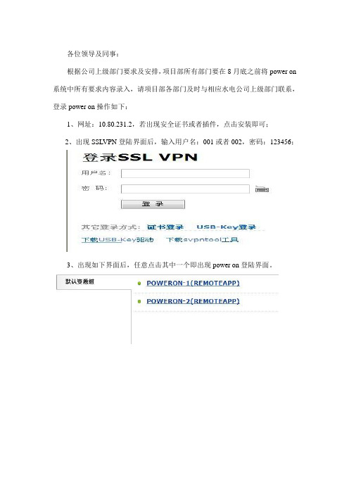
2、出现SSLVPN登陆界面后,输入用户名:001或者002,密码:123456;
3、出现如下界面后,任意点击其中一个即出现power on登陆界面。
4、用户名为自己汉语名字,无密码,登陆后请设置密码。
5、同时需点击屏幕右下角的“S”,更改相应设置:
单机右键出现的远程应用设置,将本地磁盘和剪切板打上对勾,重新登录power on系统即可。
6、目前各部门人员只能更改属于本部门的信息,登录成功后及时联系水电公司相应上级部门,确定好需要录入的信息后,请请示项目部领导后再录入。
7、关于预定义流程的设置,请到合同计量部询问。


ST Power Module User GuideTable of Contents1 Introduction (3)1.1 Description (3)1.2 Features (3)1.3 Reference Design (3)1.4 Ordering Information (3)2 Functional Description (4)2.1 Block Diagram (4)2.2 Power Module Interfaces (4)2.3 DDR Memory Voltage Select Jumper (5)2.4 Remote Sense (6)2.5 Sequencing and Startup (6)2.6 Mechanical (7)2.7 Board Image (8)2.8 Revisions (8)1IntroductionThe purpose of this manual is to describe the functionality and contents of the ST Power Module from Avnet Electronics Marketing. This document includes instructions for operating the board, descriptions of the hardware features and explanations of the header signals and functionality.1.1 DescriptionThe Power Module is designed to be used with the Avnet Mini-Module Plus developmentsystem, or any system that meets the mechanical interconnect, pinout, voltage and currentrequirements set forth in this document. The power module operates off a 12VDC inputprovided from the target baseboard. The following table shows the output voltages generated by the power module, as well as the voltage banks each rail is tied to through the baseboard when used in the Mini-Module Plus system.Xilinx power bank / FMC Voltage Voltage (V) Max Current (A)Tolerance Vccint/Vccbram 16 3.00% Vcco 1.5 / 1.354 5.00% Vccaux/Vccaux_io/Vccadc/Vcco/MGTVccaux 1.86 5.00% Vccaux_io 22 3.00% Vcco 2.58 5.00% Vcco 3.38 5.00% MGTAVcc 16 3.00% MGTAVtt/MGTAVTTrcal 1.24 2.50%Table 1 – Output Voltages1.2 FeaturesThe Power Module provides a complete power solution through the use of 3 headers. 2 headers are used to provide power between the Avnet Power Module and the target board. The 3rd header is used to provide access to remote sensing for increased regulation accuracy.There is one configurable supply provided on the board which is selectable to be either 1.5V output or 1.35V output. This supply configurability allows the Power Module to work with the Mini-Module Plus system, supporting Mini Module cards populated with either 1.5V or 1.35V DDR3 memory.1.3 Reference DesignReference design files for this board are available at:/pom-sgs11.4 Ordering InformationPart Number HardwareAES-POM-SGS1-G ST Power Module2 Functional DescriptionThe power module provides 8 sequenced output voltages with controlled rise times from a 12VDC input. The supplies are designed to meet the current and regulation tolerances outlined in table 1.2.1 Block DiagramFigure 1 - Block Diagram2.2 Power Module InterfacesThe following tables show the pinouts for J1, J2 and J3. J1 and J2 provide power and ground to and from the baseboard. J1 (Samtec part # HPM-10-05-T-S) and J2 (Samtec part # HPM-08-05-T-S) provide power to and from the board. On the baseboard, J1 mates with Samtec part # HPF-10-01-T-S and J2 mates with Samtec part # HPF-08-01-T-S.Pin 1 2 3 4 5 6 7 8 9 10 Signal GND 1.5V/1.35V GND 1.8V GND2V GND 3.3V GND12VTable 2 - J1 PinoutPin1 2 3 4 5 6 7 8Signal GND 1V GND1V(MGT)GND 1.2V GND 2.5VTable 3 - J2 PinoutJ3 (Samtec part # FW-05-05-F-D-361-085) is in place to provide access for remote voltage sense. The mating connector on the baseboard is Samtec part # CLP-105-02-F-D. The signals on this header are tied directly to the load voltage pins. This header is pinned out left to right down the header as illustrated below:1 23 45 67 89 10Table 4 - J3 DiagramPins are defined as follows:Pin 2 4 6 8 10Signal 2.5Vrm 1Vmgtrm2Vrm 1.2Vrm GNDPin 1 3 5 7 9Signal 3.3Vrm 1.8Vrm 1Vrm 1.5Vrm GNDTable 5 - J3 PinoutPin 1 location on J3 is indicated on the silk screen on the PCB. Pin 1 on J1 and J2 are the right most pins when viewing the board header side up. Refer to Figure 2 for an illustration of these pin positions.2.3 DDR Memory Voltage Select JumperJP1 sets the output of the 1.5V / 1.35V regulator. JP1 is a 2 pin header with a jumper used to connect pins 1-2. Place the jumper on pins 1-2 to set the voltage to 1.5V. Leave the jumper open to set the voltage to 1.35V. The table below shows the jumper settings and corresponding output voltage.JP1 setting Output voltageON 1.5VOFF 1.35VTable 6 – JP1 Jumper SettingsSetting the voltage to 1.5V or 1.35V is dependent on the type of memory utilized on the target board. In the case of the K7 Mini-Module for example, the DDR memory used is 1.5V.WARNING: Do NOT power up the Power Module without the jumper set to either 1.5V or 1.35V.Powering the board without the jumper in place can result in board failure.2.4 Remote SenseRemote sense is used to compensate for the power supplies being located far from the load. J3 provides a low impedance path directly to the voltage pins on the load. By allowing access to the voltage actually being seen by the load, the regulator can adjust the output to be more accurate and compensate for impedance losses through components and the PCB.When using remote sense, the signals tied to the header are traces that are terminated right at the pin of the target load. In the Mini-Module Plus case, these voltage pins are terminated right at the pins on the FPGA. The signals are then routed as traces back to the remote sense header. It is important that the signals originate from as close to the target load as possible.The signals on these pins are then used as the set point by the regulators to regulate the output voltage. By using a signal directly tied to the load as the set point, the power supplies are able to better regulate the voltage at the intended load.2.5 Sequencing and StartupSequencing of the output voltages follows Xilinx specification for 7 Series devices as follows: Vccint (1V) -> Vccaux (1.8V) -> Vccaux_io (2V) -> VccoNote that sequencing requirements are not specified for the MGT rails, they may be powered at any point during start up. The diagram below illustrates the start up sequencing of the power module.1V Vccint1.8V Vccaux2V Vccaux_io1.35V / 1.5V Vcco2.5V Vcco3.3V Vcco1V MGT1.2V MGTTiming DiagramEach rail starts up between 0.2ms and 50ms to meet ramp requirements, as well as havemonotonic rises. The requirement for power down sequencing states that the 3.3V Vcco railcannot exceed the 1.8V Vccaux rail during shut down by more than 2.625V for longer than500ms. No additional power down circuitry is needed in the power module to meet thisrequirement.2.6 MechanicalThe Power Module meets the following geometry requirements:Max Component Height 0.4”Max Board Width 3.5”Max Board Length 5.5”Clearance Between Mated Boards0.45”(power module and baseboard)Table 5Along with meeting these geometry requirements, headers J1, J2, and J3 are placed on the bottom of the board according to the definition below:Figure 1 – Mechanical Header and Mounting Hole Locations These locations are based on a topside view looking through the board. The headers are placed on the bottom. J3 is measured to the center of the connector. The mounting holes are plated through holes with a 125mil diameter. The mounting holes are not electrically connected on the module.Pin 1 locations for J1, J2 and J3 are illustrated below in Figure 2. The view is looking down on the board with the connectors facing up.Figure 2 – Header Pin 1 Locations2.7 Board Image2.8 Revisions01 Initial Release Chris Ammann。
K 系列功放K2 / K2 DSP + AESOP K3 / K3 DSP + AESOP K6 / K6 DSP + AESOP K8 / K8 DSP + AESOP K10 / K10 DSP + AESOP K20 / K20 DSP + AESOP用户手册V 2.32012年11月powersoft_K Series_uguide _en_v2.4© 2012 Powersoft DO000044REV 02Powersoft • Via Enrico Conti, 5 • 50018 Scandicci (FI) • Italy • +39055 735 0230 • sales@powersoft.it • K系列用户手册1 警告 (5)1.1重要的安全指示 (5)1.2认证 (5)1.3警告提示 (6)1.3.1 放置 (6)1.3.2安装注意事项 (6)1.4安全规则 (6)1.5 音箱损害 (6)1.6 音箱输出电击危险 (7)2 前后面板参考图 (8)3 欢迎 (11)3.1介绍 (11)3.2 K系列 (11)3.3音质更佳,重量更轻 (11)3.4 确保表演无间断正常运转 (11)4 安装 (11)4.1开包 (11)4.2安装 (12)4.3散热 (12)4.4操作防范措施 (12)4.5接地 (12)4.6交流电源连接 (12)5连接和操作 (13)5.1连接音频输出 (13)5.1.1 模拟连接 (13)5.1.2 AES/EBU 连接 (14)5.2 连接音频输出 (14)5.3内部信号通路极性 (15)5.3.1 V ext (15)5.3.2串行连接 (15)5.3.3 以太网连接 (16)5.4功放系统搭建与设置 (17)5.4.1 简介 (17)5.4.2 主屏幕与LED条 (17)5.5 前面板按钮 (18)6主菜单 (18)7功放设置 (21)7.1 输出衰减 (21)7.2 输入增益/灵敏度 (21)7.3 输入选择 (21)7.4 最大输出电压 (21)7.5 最大电源电流 (22)7.6 削波限幅器通道1-通道2 (22)7.7 门限通道1-通道2 (22)7.9 空载模式 (23)8 DSP设置 (23)8.1 DSP处理链 (23)8.2 DSP设置菜单 (24)8.2.1 通用设置 (24)8.2.1.1 源选择 (24)8.2.1.2 AES3 (24)8.2.1.3 增益微调(dB) (24)8.2.1.4 如无连接 (24)8.2.1.5 交叉限幅 (25)8.2.1.6 声音速度(m/s) (25)8.2.2 通道设置 (25)8.2.2.1 均衡 (25)8.2.2.2低通滤波器(和高通滤波器) (27)8.2.2.3极性 (27)8.2.2.4通道延时 (27)8.2.2.5增益 (27)8.2.2.6限幅器 (27)8.2.2.7阻尼控制 (31)8.3通道1/通道2设置 (31)8.3.1辅助延时 (31)8.3.2 诊断 (31)8.4输入均衡 (32)8.5 重置输入部分 (32)8.6 重置输出部分 (32)9网络操作 (32)9.1 AESOP概览 (32)9.1.1 数据流 (32)9.1.2 音频 (33)9.1.3 网络连接:以太网,AES3单向模式和中继模式 (33)9.2 网络稳健性 (35)9.3 网络连接 (36)10 KAESOP网络设置菜单 (39)10.1 设备模式 (39)10.2 寻址模式 (39)10.3 设置地址 (40)10.4 显示网络配置 (40)10.5 音频 (40)10.5.1 音频源选择 (40)10.5.2 音频源模式 (40)10.5.3 增益微调 (40)10.5.4 如无连接 (40)11 显示 (40)11.1 输出电平表 (40)11.2 温度 (41)11.3 电源电平表 (41)11.4 功放名称 (41)12.1 锁定预设 (41)12.2 锁定预设库规模 (42)12.3 调用本地预设 (42)12.4 保存本地预设 (42)12.5 更改锁定密码 (43)12.6 清除所有预设 (44)13 系统搭建 (44)13.1 硬件信息 (44)13.2 硬件监控器 (44)13.3 LCD对比度 (45)13.4 键锁定和设置键锁密码 (45)13.5 单一通道静音 (45)14 保护 (45)14.1打开/关闭静音 (45)14.2 短路保护 (45)14.3 过热保护 (46)14.4 直流故障保护 (46)14.5 输入/输出保护 (46)15 用户维修保养 (46)15.1 清洁 (46)15.2 维修 (46)15.3 除尘 (46)16 附录 (46)16.1 自定义以太网/AES3组合接头盒 (46)16.2 功放错误代码 (47)16.3 智能卡功能 (47)16.4 控制软件 (48)16.4.1 Powersoft的Armonía Pro Audio Suite (48)16.4.2 第三方控制 (48)17 技术参数表 (49)17.1 K2 (51)17.2 K2 DSP+AESOP (53)17.3 K3 (55)17.4 K3 DSP+AESOP (57)17.5 K6 (59)17.6 K6 DSP+AESOP (61)17.7 K8 (63)17.8 K8 DSP+AESOP (65)17.9 K10 (67)17.10 K8 DSP+AESOP (69)17.11 K20 (71)17.12 K20 DSP+AESOP (73)K 系列用户手册1 警告1.1重要的安全指示警告:为减少电击风险,请勿试图打开本设备的任何部件。
waters操作手册英文版Waters Operation ManualIntroductionThis manual is designed to provide detailed instructions and guidance for operating Waters equipment It is important to follow these instructions carefully to ensure accurate and efficient operationSafety PrecautionsBefore starting any operation, it is crucial to be aware of the safety precautions:1、 Always wear appropriate personal protective equipment (PPE),such as safety glasses and gloves2、 Ensure the working environment is wellventilated3、 Do not operate the equipment if you are not familiar with its functions or if it shows any signs of damageEquipment OverviewThe Waters system typically consists of several components, including the chromatographic column, detector, pump, and control unit Each component has its specific role and functionsThe chromatographic column is responsible for separating the components of the sample The detector measures the signal generated by theseparated components The pump controls the flow rate of the mobile phase, and the control unit allows for programming and monitoring of the entire processStartup Procedure1、 Power on the Waters equipment and allow it to initialize2、 Check the connections of all components to ensure they are secure3、 Set the appropriate parameters in the control unit, such as flow rate, wavelength for the detector, and run timeSample Preparation1、 Prepare the sample according to the specific requirements of the analysis2、 Filter the sample to remove any particulate matter that could clog the systemInjection of Sample1、 Use a precise syringe to inject the sample into the injection port2、 Ensure the injection volume is within the specified rangeMonitoring the RunDuring the chromatographic run, monitor the signals from the detector on the display of the control unit Keep an eye on any abnormal peaks or fluctuations that could indicate a problemData AnalysisAfter the run is completed, the collected data can be analyzed using the software provided with the Waters system This may include peak identification, integration, and calculation of concentrationsMaintenance and TroubleshootingRegular maintenance is essential to keep the Waters equipment in optimal condition This includes cleaning the chromatographic column, checking the pump seals, and calibrating the detectorIf you encounter any problems during operation, refer to the troubleshooting section of this manual Common issues such as pressure fluctuations, baseline noise, or no signal may have specific solutions listedShutdown Procedure1、 At the end of the operation, stop the pump first2、 Turn off the detector and the control unit3、 Disconnect the power supplyIt is important to note that the specific procedures and parameters may vary depending on the model and configuration of your Waters equipment Always refer to the manufacturer's documentation for detailed and accurate informationWe hope this manual provides you with a clear understanding of operating the Waters equipment If you have any further questions or need additional support, please contact the manufacturer's customer serviceRemember, proper operation and maintenance will ensure the longevity and accuracy of your Waters system for reliable analytical results。
12目录软件概述 ................................................................................................................................................. 1 时标网络图 .............................................................................................................................................. 1 项目列表 ................................................................................................................................................. 4 工作分解结构(WBS ) .......................................................................................................................... 4 作业表格和横道图 ................................................................................................................................... 4 定义日历 ................................................................................................................................................. 5 关键指标 ................................................................................................................................................. 6 责任分配 ................................................................................................................................................. 6 进展反馈责任人 ...................................................................................................................................... 7 赢得值分析 .............................................................................................................................................. 7 形象进度图 .............................................................................................................................................. 8 目标计划 ................................................................................................................................................. 8 过滤器 ..................................................................................................................................................... 9 视图 ......................................................................................................................................................... 9 作业模板 ................................................................................................................................................. 9 软件使用许可 ........................................................................................................................................ 10 在线帮助 ............................................................................................................................................... 10 进展反馈(Power Reporter ) .. (11)上海普华科技发展股份有限公司1软件概述时标网络图Power Highlight 软件主要用于项目进度计划的编制和展示。
工程档案及竣工资料管理系统 – PowerDocumentation 操作手册 - 1 - 上海普华应用软件有限公司 目录 1.系统初始化 ............................................................................................. 3 2.文件管理 ................................................................................................. 7 2.1工程管理.......................................................................................................... 7 2.2文件分类.......................................................................................................... 8 2.2.1TBS ........................................................................................................ 8 2.2.2WBS ..................................................................................................... 11 2.2.3WBS&TBS导入导出 ......................................................................... 13 2.3文件维护........................................................................................................ 14 2.3.1文件信息维护(录入、修改和删除等)......................................... 14 2.3.2文件相关问题..................................................................................... 15 2.3.3批量导出文件..................................................................................... 16 2.3.4回收站管理......................................................................................... 19 2.3.5自定义分类码..................................................................................... 20 3.档案管理 ............................................................................................... 21 3.1档案库管理.................................................................................................... 21 3.2案卷管理........................................................................................................ 22 3.2.1合卷..................................................................................................... 23 3.2.2拆卷..................................................................................................... 24 3.2.3案卷整理............................................................................................. 25 3.3辅助立卷........................................................................................................ 26 3.4已组卷文件.................................................................................................... 28 3.5ABS ................................................................................................................. 29 4.文件流转 ............................................................................................... 29 4.1文件审批........................................................................................................ 30 4.2联系单位/联系人 .......................................................................................... 33 4.3收发文............................................................................................................ 34 5.系统管理 ............................................................................................... 37 工程档案及竣工资料管理系统 – PowerDocumentation 操作手册 - 2 - 上海普华应用软件有限公司 5.1OBS ................................................................................................................. 37 5.2权限管理........................................................................................................ 38 5.2.1功能权限............................................................................................. 38 5.2.2保密文件类型..................................................................................... 39 5.2.3 TBS数据权限 .................................................................................... 40 5.2.4 WBS数据权限 ................................................................................... 41 5.3参数列表框.................................................................................................... 42 5.4帮助................................................................................................................ 43 5.5注册................................................................................................................ 44 6.外部工具 ............................................................................................... 45 6.1P3 WBS结构导出工具 .................................................................................. 45 6.2数据库登录密码加密工具............................................................................ 45