FEMAG晶体生长计算软件之Float Zone Process (FEMAG-FZ)
- 格式:doc
- 大小:326.50 KB
- 文档页数:4

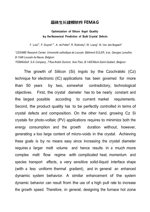
晶体生长建模软件FEMAGOptimization of Silicon I n go t Q ual it yby the Numerical P r e d i c ti on of Bulk Crystal D e f ec t sF. Loix2*, F. D upr e t1,2*, A. de Potter2, R. R ol i n s ky2, W. L i a ng2, N. Van den Boga e rt21CESAME Rese a r ch C e nt e r, Uni v e r s i técatho li que de L ouva i n,Bât i m e nt EULER, 4 av. Georges L e maît r e,B-1348 Louva i n-l a-N e uv e,B e l g i um2FEMAGSoft S.A. Company, 7 Rue André Dumont, Ax i s Parc, B-1435 Mont-Saint-Guibert, B e l g i um The growth of S ili c on(Si) i ngot s by the Czoc hra l s ki (Cz) technique for e l ec t roni c (IC) a ppl i ca t i ons has been governed for more than 50 years by two, somewhat c ont ra di c t ory, t ec hnologi ca l obj ec t i ve s. First, the c rys t a l diameter has to be nearly constant and the l arge s t pos s i bl e according to current market requirements. Second, the product quality has to be pe rfe c t l y c ont rol l e d in terms of c rys t a l defects and composition. On the other hand, grow i ng Cz S i c rys t a l s for photo-volt a i c(PV) a ppl i ca t i ons requires to m i ni m i ze both the energy cons umpt i on and the growth dura t i on without, however, genera t i ng a too l arge content of m i c ro-voi ds in the c rys t a l.A c hi e vi ng these goa l s i s by no means easy s i nc e i nc rea s i ng the c rys t a l diameter re qui re s a l arge r m e l t volume and hence results in a much more complex m e l t flow regime with c om pl i ca t e d heat, momentum and s pec i e s transport effects, a very s ens i t i ve s ol i d-li quid i nt e rfa ce shape (with a l e ss uniform t he rm a l gradient), and in genera l an enhanced dynamic s ys t e m behavior. A s i m il a r enhancement of the system dynam i c behavior can result from the use of a high pull rate to i nc rea s e the growth speed. Therefore, in genera l,de s i gning the furnace hot zonewill require to i ntroduc e appropriate heat s hi e l ds in order to w e ll-cont rol the ra di a t i on hea t transfer whi l e a s a t i s fa c t ory m e l t flow pattern can only be obt a i ne d for l arge diameter c rys t a l s by the ac t i on of transverse or configured m agne t i c fi e l ds.Moreover the s e l ec t i on of opt i m a l proc e ss parameters (heater power, c rys t a l pulling rate, c rys t a l and c ruc i bl e rot a t i on rates, m agne t i c fi e l d i nt ens i ty if any, ambient gas flow rate, etc.) becomes much more difficult in vi e w of the i nc rea s e d system nonl i nea rity and t i m e-depende ncy,e s pec i a ll y during the c rit i ca l process stages (necking, shouldering, t a il-e nd stage, c rys t a l detachment, …).N one t he l e ss,compared to the high difficulty to address these different t ec hnologi ca l i ss ue s,it i s worth observing that huge progress has been achieved in the l a s t decades in s e ve ra l s c i e nt i fi c dom a i ns.F i r s t, the phys i c s of ra di a t i on and c onve c t i on in Cz furnaces, and of defect form a t i on and transport in growing S i c rys t a l s,i s much better known, and hence the m a t he m a t i ca l m ode l s governing Cz S i c ry s t a l growth are better and better e s t a bl i s he d.In spite of the i mport a nt i mprovem e n t s that re m a i n necessary in the m ode li ng of turbulence in the m e l t a nd the ambient gas (i nc l uding the m ode li ng of m e l t turbulence under the effect of a m agne t i c fi e l d) and of the s t ill i ns uffi c i e nt kno w l edge of the m a t e ri a l parameters governing point-and micro-defect e vol ut i on in S i s i ngl e c rys t a l s,an a l m os t complete picture of the phy s i c s of S i growth today i s a va il a bl e.Secondly, num e ri ca l methods and computers have a l s o quickly progre ss e d s i nc e the de ve l opm e n t of the first m ode l s of Cz growth achieved in the 1980’s. Nowadays the qua s i-s t ea dy or t i m e-depende nt s i m ul a t i on of the Cz process hasbecome po ss i bl e in an acce pt a b l e c omput i ng t i m e,with s uffi c i e nt l y refined meshes to resolve the key de t a il s of the problem, and with appropriate num e ri ca l techniques to handle the system de form i ng ge om e try (which comprises s e ve ra l moving components together with free boundaries such as the m e l t-c rys t a l and m e l t-ga s i nt e rfa ce s).Therefore, having at one’s di s posa l the appropriate phys i ca l m ode l s, num e ri ca l tools a nd computer hardware, the route i s directly opened to process opt i m i za t i on by means of num e ri ca l s i m ul a t i on.The obj ec t i ve of the present paper i s to ill us t ra t e how this strategy can be a ppl i e d by use of the FEMAG-CZ software as today co-de ve l ope d by FEMAG Soft S.A. Company and the CESAME research center of the Uni ve rs i téde L ouva i n (Belgium).We will here focus on the S i ingot quality pre di c t i on and i t s opt i m i za t i on.We present a fully t i m e-depende nt m ode l devoted to predict the gl oba l heat transfer in the furnace, the s ol i d-liquid i nt e rfa ce shape, and the re s ult i ng di s tri but i ons of point-and m i c ro-de fe c t s as ca l c ul a t e d from the S i nno-Dornbe rge r (S-D) model together with an e xt ens i on of the l um pe d model of Voronkov and Kulkarni. All the t rans i e nt s are cons i dere d including the effects of c rys t a l a nd c ruc i bl e lift, of the heat capac i t i e s of the furnace cons t i t ue nt s, of the t he rm a l i ne rt i a of the s ol i di fi ca t i on front, and of the dynam i c defect governing l a w s.We hence show that dynamic effects deeply affect the defect di s tri but i on in the c rys t a l(fig 1.). In a ddi t i on to the c l a ss i ca l point-defect e vol ut i on mechanisms, a new l um pe d m ode l i s de ve l ope d to ca l c ul a t e theform a t i on a nd growth of m i c ro-de fe c t s in order to predict their dens i t i e s and s i ze di s tri but i ons anywhere in the c rys t a l.Another key i ss ue in Cz S i growth i s to control the dens i ty of oxygen and any other s pec i e s(i nc l uding dopants and i mpuri t i e s) i ns i de the c rys t a l. M ode li ng i ss ue s will be here aga i n de t a il e d.Finally, off-line process control pri nc i pl e s will be addressed. Results will ill us t ra t e how this tool can he l p in opt i m i z i ng c rys t a l shape and quality.P r e di c t e d defect de l t a C i-C v di s t r i bu t i on (C i, C v be i ng the conc e nt r at i on of i n t e r s t i t i al s , vacanc i e res p e c t i v e l y) with a quas i-s t e ady (a) and a t i me-d e pendent (b)simulation. The OSF ring is located at the position where delta~= 0. This picture highlights the strong impact on the point defect of the transient effects in the growing crystal.。


晶体⽣长建模软件FEMAG介绍(⼋)--FEMAGPVT(物理
⽓相传输法)
FEMAG/PVT软件的主要功能
FEMAG/PVT软件⽤于模拟物理⽓相传输法(Physical Vapor Transport process,PVT)晶体⽣长⼯艺,可以⽤于碳化硅单晶体、氮化铝、氧化锌多晶体等的PVT法⽣长⼯艺过程的模拟。
FEMAG/PVT软件的典型应⽤
FEMAG/PVT软件的典型应⽤是模拟碳化硅单晶的PVT法⽣长过程。
图1是碳化硅晶⽚。
碳化硅(SiC)是⼀种优质的宽带隙半导体材料,具有宽禁带、⾼击穿电场、⾼热导率、⾼饱和电⼦漂移速率等优点,可以满⾜⾼温、⼤功率、低损耗⼤直径器件的需求。
SiC单晶⽆法经过熔融法形成,⽽基于改进型Lely法的升华⽣长技术——物理⽓相传输法是获得SiC单晶的常⽤⽅法。
PVT法制备SiC单晶的⽣长原理是:⾼纯SiC粉源在⾼温下分解形成⽓态物质(主要为Si、SiC2、Si2C),这些⽓态物质在过饱和度的驱动下,升华⾄冷端的籽晶处进⾏⽣长。
过饱和度是由籽晶与粉源之间的温度梯度引起的。
图2是利⽤FEMAG/PVT软件计算碳化硅沉积腔内的温度梯度的结果。
FEMAGCZVersion 2.10Homework 2wxCreGeoDecember 10, 2008FEMAG Soft S.A. LouvainlaNeuve, Belgium Table of Contents1. HOMEWORK GOALS (4)2. ASSOCIATED FILES (4)3. WXCREGEO (4)3.1. Starting wxCreGeo (4)3.2. Import geometry file (5)3.3. Material file (5)3.4. Set material properties (5)3.5. Change the material parameters (8)3.6. Set operating conditions and computational parameters (8)3.7. Ending (10)4. CONTROL ARCHIVE FILE (10)5. SUMMARY (10)5.1. Program features and file results (10)5.2. Procedures: if I want to (11)5.3. Important remark (11)FEMAGCZ 2.10Homework 22Typographic attributes used in this manualSymbols used in this manualContactsupport@FEMAGCZ 2.10Homework 23Homework goals1. Homework goalsAt the end of this homework, you should be able:–to visualize your 2D mesh.–to assign the appropriate material type to the different parts of the puller and hence to set the material properties to each part.–to set the operating process conditions (kinematics, thermal conditions, gas and melt flow, magnetic field).–to set the computational parameters (local and global convergence criteria, time duration of a step (if time dependent problem)).2. Associated filesThis homework is based on the previous homework, the corresponding archive being “ctrl_geotool.tgz”.If required, please extract the “ctrl_geotool.tgz” archive in the “training/” working directory.3. wxCreGeowxCreGeo is the FEMAGCZ module used for mesh visualization and for the input of all material parameters, boundary conditions, operating conditions, and computational parameters.3.1. Starting wxCreGeoStart wxCreGeo by running wxcregeo from your working directory.wxCreGeo is organized in two windows:•the main window organized in four parts: the menu bar, main field, computation log and status line.•the “Plot/Tree View” window (Illustration 1) displaying the geometry and the list of macroelements composing the geometry.Closing the main window terminates the program. Closing secondary (plot and tree view) windows hides them. Using right mouse button in plot and tree view gives access to the pulldown menu commands.FEMAGCZ 2.10Homework 24Illustration 1 Geometry mesh display3.2. Import geometry fileImport the files containing the mesh by means of File>Import project..., choose the “training.ini” file, and press <OK>.In the plot panel of “Plot/Tree View” window (Illustration 1), you can visualize the 2D mesh by pressing <Display/hide mesh>. In the tree list of the same window, you can see the list of the macroelements.3.3. Material fileThe material data are stored in a database. FEMAGCZ uses two databases:–The default database is linked to the wxCreGeo user interfaces, and proposes default material data. The default database is loaded with the wxCreGeo interface opening. This database is stored on your computer system into a material file using the “.mat” filename extension.–The current database is linked to a specific model, and proposes the material data linked to this model. This material database is loaded when the specific model is opened in wxCreGeo. This database is stored in the “.h5” file corresponding to the model.A standard material database, “default.mat” had to be installed with FEMAGCZ.If you have not yet created your own material files, copy the default one “default.mat” provided with FEMAGCZ distribution into another name, e.g. “myFile.mat”. It is better to work with your own material file because, in case of new FEMAGCZ installation, existing “default.mat” could be replace by the default file.3.4. Set material properties1.In the main window, select Option>Materials file..., and choose the materials file you will use(“myFile.mat”).Run Materials>reset to default to update the current material database.2.For each 1D, 2D or melt/crystal macroelement, set its material properties: with the right mousebutton, click on it in the plot panel or in the tree list and select Set Material from the pulldown menu. In the material selection box you have to choose between:•a predefined material from the list. These predefined materials are stored in the materials file.•a “local” noname material associated only with the concerned macroelement. In this case, you have to complete the material setting sheet.We use the following predefined materials:FEMAGCZ 2.10Homework 25Click on it and select your material For example, in order to set material for the melt/crystal macroelement, click on “mc” in the tree list and select Set Material from the tree view pulldown menu. Then, choose “Silicon” from thematerial predefined list (Illustration 2).FEMAGCZ 2.10Homework 263.In order to easily visualize the macroelement material in the plot panel, you can assign a color to each material.Two possible ways:•Materials>Edit current...: to edit the current material database, i.e. changes will only be taken into account for the current model.•Materials>Edit default...: to edit the global material database, i.e. changes will be saved in the materials file and taken into account for all other geometries.In the materials editor, set the material colors (Illustration 3), select File>Save and finally, File>Exit . Come back in wxCreGeo main window, to take changes into account you have to do:•View>Refresh , if you performed changes by Edit current...•Materials>Reset to default followed by View>Refresh , if you performed changes by the other way.To turn filling on/off, select View>Fill 2D(i).FEMAGCZ 2.10Homework 27Click in the field and choose your color3.5. Change the material parameters1.Change the insulator thermal conductivity of the global database:1.Run Materials>Edit default... .The default database (as defined in Options>Material File...) is automatically loaded in the material editor window. Remind you that this database is linked to the wxCreGeo user interfaces. It is loaded with the wxCreGeo interface opening.2.In the “Solid materials” panel, select the “Insulator” item from the material list.3.Change the thermal conductivity from 1 W/mK to 0.15 W/mK.4.select File>Save and File>Exit.Come back in wxCreGeo main window, to take changes into account you have to run Materials>Reset to default followed by View>Refresh.2.Change the molten silicon thermal conductivity only for the current simulation problem:1.Run Materials>Edit current...2.The current database is automatically loaded in the material editor window. Remind you thatthe current is linked to the model you are editing, and proposes the material data linked to this model. This material database is loaded when the specific model is opened in wxCreGeo. This database is stored in the “.h5” file corresponding to the model.3.In the “2Di materials”, select the “Silicon [FEMAGSoft 2005]” item from the material list.4.Change the melt thermal conductivity from 42.9 W/mK to 110 W/mK.5.select File>Save and File>Exit.Come back in wxCreGeo main window, to take changes into account you have to run View>Refresh.In case of simulation without melt convection computation, the effect of the melt flow on the heat transfer can still be modeled by means of an enhanced melt thermal conductivity of the molten silicon, which sums up the contributions of heat convection and diffusion.3.You can check by means of Materials>Edit default... that the molten silicon thermal conductivityin the default database is still 42.9 W/mK. Whereas, the insulator thermal conductivity is set to0.15 W/mK in both databases.3.6. Set operating conditions and computational parameters◆Kinematics•Set the seed velocity to 0.1 mm/min.•Keep gravity to 9.81 m/s2.•Set the crystal rotation rate to 20 RPM.Define the following domains as rotating with the crystal: “training_pull_rod” and “mc”.•Set the crucible rotation rate to 15 RPM.Define the following domains as rotating with the crucible: “cement”, “training_crucible” and “training_support” (use “Select” button to access the selection window).◆Thermal operating conditions•Set a specific adaptive power of 10,000 [W/m3] on the heater macroelement (training_heater).Select the “training_heater” macroelement from the list, imposed a specific power of 10,000 W/m3, select “adaptive” option and click on <Apply>.The actual heater power will be computed in order that the computed temperature of the trijunction point fit with the crystal melting temperature.FEMAGCZ 2.10Homework 28•Specify external boundary conditions (Illustration 4) by pressing on the corresponding button. Keep a temperature of 300 K along the furnace shell except for gas outlet having a flux boundary condition q=100*(T300) W/m 2.•We do not use particular emissivities and additional fluxes.In order to specify particular emissivities and additional fluxes you have to press the corresponding button to open the dialog window. Choose sides alternatively and specify value for T0, h and emissivity. Then, press <OK>.•We do not have to define additional temperature control points.Please remember that the actual heater power will be computed in order that the computed temperature of the control point fit with the imposed temperature. In case of ingot growth, the trijunction point is constrained to be a temperature control point.The number of temperature control point has to be equal to 1 or to the number of adaptive heater power. Hence, in the current case, the number of adaptive heater power being equal to 1, the number of temperature control point must be equal to 1.◆Gas flow mode l •Select the “e01_gas” gas enclosure item.•Tick off “With inlets and outlets” box and specify the inlet sides ID's and the outlet side ID's. Please remember that several inlet/outlet sides can be defined.•Set the furnace pressure to 0.015 bar.•Set the flow rate per inlet side by pressing the corresponding <Edit> button. For the inlet side ID 180, impose a flow rate of 0.030 m 3/s at the specified pressure. Click on <Apply>.•Set the gas flow computational parameters:–The relaxation coefficient allows to relax the effect of the gas flow on the temperature field.The relaxation coefficient can be increased to 0.8 ... 0.9 in case of horizontal temperature profile in cavity. However, by increasing the relaxation coefficient, you increase the iteration number and hence the computational time.Please note that the global solution is not affected by this parameter.Keep default value (0.5).–The convergence criterion can be used to reduce the computational accuracy. This is interesting in case of intermediate computations such as used in stepbystep procedure. In this case, decrease the accuracy for intermediate computation and increase it for the final solution. As the accuracy is reduced, the computational time is reduced, too.Define a value of 1.0e05.•Click on <Apply>.FEMAGCZ 2.10Homework 29Illustration 4: External boundary conditiondialog box.◆Melt flow modelThis panel allows to choose the melt flow model parameters. This panel can be neglected in a first stage.◆Magnetic fieldsWe do not yet use magnetic fields. The data related to magnetic field will be set in a later stage.◆Computational parametersYou have to define the crystal and melt boundary conditions by pressing the corresponding button. Define a temperature condition along crystal wall and melt free surface (except on the sides adjacent to the trijunction point), while keeping default parameter elsewhere. Change the convergence criteria for the global and local iterations to:–Trijunction temperature: 0.1 K.–Interface position: 0.1 mm–Convergence tolerance: 1.000e04.3.7. EndingSave input data as “couplage/data/training.h5” file by doing File>Save.When everything is completed, do File>Export Geometry to generate files needed for the computation. Now, you can exit wxCreGeo and start your FEMAGCZ simulation.Note: When running wxCreGeo in a later stage, you can read the “training.h5” file by doing File>Open (useful to make modifications).4. Control archive fileMake the “ctrl_wxcregeo.tgz” control archive file of your working directory (Linux command: tar cvzf ctrl_wxcregeo.tgz ./*) and send it to support@.5. Summary5.1. Program features and file resultswxcregeo program:–Main actions: to assign material properties to the different parts of the puller and to define the operating conditions and the computational parameters.–Input:–material data (“./couplage/exe/default.mat”)–operating conditions (kinematics, thermal conditions, gas and melt flow, magnetic field)–computational parameters (local and global convergence criterions, time duration of a step (if time dependent problem))–Output files:–“./couplage/data/GID.h5” (produced by File>Save): file produced to be opened by wxCregeo in order to make modifications to the project.FEMAGCZ 2.10Homework 210Summary5.2. Procedures: if I want to ...If I want to change the insulator thermal conductivity of the global database:1.Run Materials>Edit default... .2.The default database (as defined in Options>Material File...) is automatically loaded in thematerial editor window. Remind you that this database is linked to the wxCreGeo user interfaces. It is loaded with the wxCreGeo interface opening.3.In the “Solid materials” panel, select the “Insulator” item from the material list.4.Change the thermal conductivity from 1 W/mK to 0.15 W/mK.5.select File>Save and File>Exit.Come back in wxCreGeo main window, to take changes into account you have to run Materials>Reset to default followed by View>Refresh.If I want to change the molten silicon thermal conductivity only for the current simulation problem:1.Run Materials>Edit current...2.The current database is automatically loaded in the material editor window. Remind you that thecurrent is linked to the model you are editing, and proposes the material data linked to this model.This material database is loaded when the specific model is opened in wxCreGeo. This database is stored in the “.h5” file corresponding to the model.3.In the “2Di materials”, select the “Silicon” item from the material list.4.Change the melt thermal conductivity from 42.9 W/mK to 110 W/mK.5.select File>Save and File>Exit.Come back in wxCreGeo main window, to take changes into account you have to run View>Refresh.5.3. Important remarkWhen inverse simulations are considered, namely when the heater power required to growth a prescribed ingot shape is looked for, the number of adaptive power has to be at least equal to the number of control points. In case of ingot growth, the trijunction point is constrained to be a temperature control point. Therefore, at least one macroelement has to be defined has adaptive in that case.FEMAGCZ 2.10Homework 211。
femag晶体生长数值模拟技术在光学行
业的应用
FEMAG晶体生长数值模拟技术在光学行业的应用
光学行业作为现代科技的重要组成部分,对于高质量光学晶体的需求日益增长。
在这一背景下,FEMAG晶体生长数值模拟技术的出现,为光学行业带来了革命性的改变。
FEMAG是一款专业的晶体生长模拟软件,其具备世界领先的仿真精度,能够优化各种光学晶体的生产质量,提高生产效率和成品率。
在光学晶体生产过程中,晶体生长工艺的控制至关重要。
FEMAG软件能够模拟晶体生长过程中的全局熔体气体对流与热场分析,帮助工程师们精确控制晶体生长的条件。
无论是提拉法、区熔法、定向凝固法还是坩埚下降法,FEMAG都能提供精准的模拟,从而优化热场,提高晶体质量,减小能耗。
例如,在直拉法单晶硅的生产中,FEMAG能够模拟不同气体流量下的全局对流,通过热场图和流场图的分析,工程师们可以更加准确地掌握晶体生长的状态,从而调整工艺参数,实现晶体质量的最大化。
这不仅降低了生产成本,还提高了产品的竞争力。
除了在单晶硅生产中的应用,FEMAG在蓝宝石、砷化镓、YAG等光学晶体的生产中也发挥了重要作用。
这些晶体在激光、光纤通信、太阳能电池等领域有着广泛的应用,FEMAG的应用无疑为这些领域的发展提供了强有力的支持。
总的来说,FEMAG晶体生长数值模拟技术在光学行业的应用,不仅提高了晶体生长的质量,还降低了生产成本,提高了生产效率。
随着技术的不断进步,FEMAG将会在光学行业发挥更加重要的作用,推动光学科技的持续发展。
FEMAG晶体生长计算软件
Float Zone Process (FEMAG-FZ)
FEMAG区熔法软件(FEMAG-FZ)用于模拟区熔法生长工艺
(FZ, PFZ)
FEMAG区熔法软件专注于设计新的热场,并研发新的方法以满足新的商业需求
点,比如:
无缺陷晶锭生长
提高成品率
节省R&D成本
FEMAG区熔法软件因为降低了试验成本而显著节省研发费用。
区熔法工艺的等温线预测
无缺陷晶锭生长
无缺陷晶体硅生长是世界上最大的难点之一。FEMAG模拟软件
能够帮助工程师运用自己独一无二的技术生长出无缺陷晶体。
半导体晶体缺陷决定了晶锭的市场价格。通过FEMAG软件的缺陷工程模块,晶
体生长行业工作者能够轻松预测晶体炉中生长的晶体质量。
缺陷工程模块能够洞悉硅、锗生长过程中填隙原子,空位和微孔演变过程。
FEMAG-FZ能够成为你的测试平台,试验在不同的操作条件下对于晶体生长质
量的影响,如
热场设计
晶体和馈送棒的旋转速率
晶体提拉速度,馈送棒的推送速度
一旦研究出上述的依赖关系,就能够控制工艺过程,获得最理想而省时的晶体生
长条件。
FEMAG预测区熔法生长晶体缺陷
提高成品率
您曾经考虑过是什么限制了您的晶体生长生产潜力以达到最大产量吗?您知道
这些限制因素对产出的影响吗?
FEMAG区熔法模拟软件可以帮助您在晶体生长过程的每一个时刻追踪关键参
数的变化。
区熔法模拟软件为工程师们提供了在晶体生长过程中凝固前沿形状,热弹性应
力,溶体流动形态等信息。FEMAG FZ模块的用户可以通过上述的参数信息优
化其工艺条件,从而增加凝固生产效率和产出。
节省R&D成本
FEMAG区熔法模拟软件能够降低您的研发成本,区熔法生长的
领先用户擅于使用FZ模拟软件来减少实验成本并增加投资回报。
这些模拟工作旨在复现固液界面的实验结果,并将数值模拟的结果与晶锭的光扫
描观测结果进行对照。
模拟晶体转速对熔体流动的影响