【EP3527447A1】CONTROLDEVICEANDCONTROLMETHODFORHYBRI
- 格式:pdf
- 大小:295.02 KB
- 文档页数:14
Printed by Jouve, 75001 PARIS (FR)(19)EP3 582 071A1*EP003582071A1*
(11)EP3 582 071A1(12)EUROPEAN PATENT APPLICATION(43)Date of publication: 18.12.2019Bulletin2019/51(21)Application number: 19163770.1(22)Date of filing: 19.03.2019(51)Int Cl.:
G06F3/01(2006.01)
(84)Designated Contracting States: AL AT BE BG CH CY CZ DE DK EE ES FI FR GB GR HR HU IE IS IT LI LT LU LV MC MK MT NL NO PL PT RO RS SE SI SK SM TRDesignated Extension States: BA MEDesignated Validation States: KH MA MD TN(30)Priority:20.03.2018US 201815926344(71)Applicant: Johnson & Johnson Vision Care, Inc.
Jacksonville, FL 32256 (US)
(72)Inventors:
•Quinteros, ErnestoNew Brunswick, NJ New Jersey 08933 (US)•Caride, VicenteNew York, NY New York 10001 (US)
(74)Representative: Carpmaels & Ransford LLP
One Southampton RowLondon WC1B 5HA (GB)
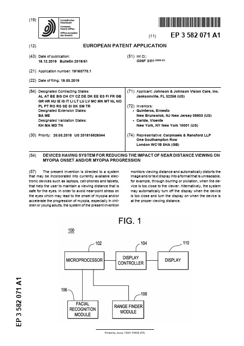
(54)DEVICES HAVING SYSTEM FOR REDUCING THE IMPACT OF NEAR DISTANCE VIEWING ON MYOPIA ONSET AND/OR MYOPIA PROGRESSION
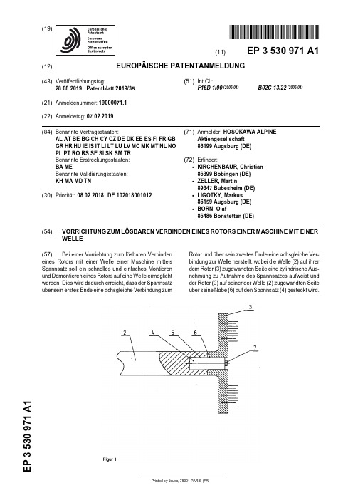
Printed by Jouve, 75001 PARIS (FR)(19)E P 3 530 971A 1TEPZZ¥5¥Z97_A_T(11)EP 3 530 971A1(12)EUROPÄISCHE PATENTANMELDUNG(43)Veröffentlichungstag:28.08.2019Patentblatt 2019/35(21)Anmeldenummer: 19000071.1(22)Anmeldetag: 07.02.2019(51)Int Cl.:F16D 1/00(2006.01)B02C 13/22(2006.01)(84)Benannte Vertragsstaaten:AL AT BE BG CH CY CZ DE DK EE ES FI FR GB GR HR HU IE IS IT LI LT LU LV MC MK MT NL NO PL PT RO RS SE SI SK SM TR Benannte Erstreckungsstaaten: BA MEBenannte Validierungsstaaten: KH MA MD TN(30)Priorität:08.02.2018DE 102018001012(71)Anmelder: HOSOKAWA ALPINEAktiengesellschaft 86199 Augsburg (DE)(72)Erfinder:•KIRCHENBAUR, Christian 86399 Bobingen (DE)•ZELLER, Martin89347 Bubesheim (DE)•LIGOTKY, Markus 86159 Augsburg (DE)•BORN, Olaf86486 Bonstetten (DE)(54)VORRICHTUNG ZUM LÖSBAREN VERBINDEN EINES ROTORS EINER MASCHINE MIT EINER WELLE(57)Bei einer Vorrichtung zum lösbaren Verbindeneines Rotors mit einer Welle einer Maschine mittels Spannsatz soll ein schnelles und einfaches Montieren und Demontieren eines Rotors auf eine Welle ermöglicht werden. Dies wird dadurch erreicht, dass der Spannsatz über sein erstes Ende eine achsgleiche Verbindung zumRotor und über sein zweites Ende eine achsgleiche Ver-bindung zur Welle herstellt, wobei die Welle (2) auf ihrer dem Rotor (3) zugewandten Seite eine zylindrische Aus-nehmung zu Aufnahme des Spannsatzes aufweist und der Rotor (3) auf seiner der Welle (2) zugewandten Seite über seine Nabe (6) auf den Spannsatz (4) gesteckt wird.EP 3 530 971A12510152025303540455055Beschreibung[0001]Die Erfindung betrifft eine Vorrichtung zum lös-baren Verbinden eines Rotors einer Maschine mit einer Welle nach dem Oberbegriff der Anspruchs 1.[0002]Rotoren von verfahrenstechnischen Maschi-nen, wie beispielsweise Zerkleinerungsmaschinen und Windsichter, werden über Passfederverbindungen,Spannsatzverbindungen oder Kegelsitze miteinander verbunden. Sie dienen als lösbare Verbindungen und der Drehmomentenübertragung von der Welle auf den Ro-tor.Bei schnelllaufenden Maschinen ist der Einsatz von Passfederverbindungen aufgrund ihres großen Pas-sungsspiels nicht geeignet. Der Rotor wird zudem mit einer Schraubenverbindung verschraubt. Diese Schrau-benverbindung muss mit dem entsprechenden Anzugs-moment angezogen werden, damit sie sich nicht löst. Um dieses Anzugsmoment aufbringen zu können, muss ent-sprechend gegengehalten werden. Dies erfordert immer aufwendige Gegenhalteeinrichtungen.Auch bei Kegelsitzverbindungen ist zum Anziehen der Schraubenverbindung eine Gegenhaltevorrichtung er-forderlich. Bei Demontage muss nach dem Lösen der Schraubenverbindung zusätzlich der Kegelpressver-band mit Hilfe einer Vorrichtung auseinander gepresst werden.Bei den bekannten Spannsätzen wird der Spannsatz auf die Welle montiert und die Nabe des Rotors sitzt auf dem Spannsatz und beide Bauteile werden miteinander ver-spannt. Dies lässt sich nur bei großen Nabendurchmes-sern mit entsprechender Nabendicke realisieren[0003]Aufgabe der Erfindung ist es eine Vorrichtung zur lösbaren Verbindung von Rotor und Welle zur Ver-fügung zu stellen, die ein schnelles und einfaches Mon-tieren und Demontieren eines Rotors auf eine Welle er-möglicht.[0004]Die Aufgabe wird durch eine Vorrichtung nach dem Kennzeichen des Anspruchs 1 gelöst.[0005]Bei der erfindungsgemäßen Vorrichtung zur lösbaren Verbindung eines Rotors einer Maschine mit einer Welle mittels Spannsatz wird der Spannsatz zu ei-nem Teil von der Welle und zum anderen Teil vom Rotor aufgenommen. Dafür ist die Welle auf ihrer dem Rotor zugewandten Seite mit einer zylindrischen Ausnehmung ausgebildet in die der Spannsatz eingesetzt wird. Auf die andere Seite des Spannsatzes wird der Rotor über seine Nabe aufgeschoben. Der Spannsatz wird über eine Spannmutter vom Arbeitsraum der verfahrenstechni-schen Maschine von der wellenabgewandten Seite des Rotors verspannt. Der Spannsatz wird vollständig von Welle und Rotor umgeben. Idealerweise wird der Spannsatz je zur Hälfte von der Welle und dem Rotor aufgenommen.[0006]Der Spannsatz wird mit leichter Übergangpas-sung in die Welle geschrumpft, während der Rotor ein leichtes Spiel auf dem Spannsatz hat. Durch Anziehen des Spannsatzes wird der Spannsatz in der Welle unddem Werkzeug fixiert.[0007]Wird der Spannsatz gelöst, gibt er den Rotor frei, sodass dieser von der Welle abgenommen und aus-getauscht werden kann. Der Spannsatz selber verbleibt aufgrund seines leichten Übermaßes in der Welle. Ist ein Austausch des Spannsatzes notwendig wird er aus der Welle gelöst und ausgetauscht.[0008]Als Spannsatz kommen bevorzugt hydrauli-sche Spannsätze zum Einsatz. Diese zeichnen sich durch eine geringe Einbaugröße mit hoher Kraftübertra-gung aus.[0009]Anwendung findet diese Art der lösbaren Ver-bindung von Rotor und Welle beispielsweise in verfah-renstechnischen Maschinen wie Zerkleinerungsmaschi-nen, Windsichter oder Mischer. Die Erfindung ist nicht auf diese Anwendungsbeispiele beschränkt.[0010]Eine solche lösbare Verbindung von Welle und Rotor kennzeichnet sich neben einem leichten und schnellen Ein- und Ausbaus des Rotors durch seine ge-ringen Anzieh- und Lösedrehmomente an einer Schrau-be aus.Der Einsatz von Abziehvorrichtungen die bei Kegelsitz-Verbindungen notwendig sind, entfallen hier. Dies macht die Verbindung interessant für den Einsatz von verfah-renstechnischen Maschinen in Isolatorsystemen für pharmazeutische Anwendungen, da hier einfach zu be-dienende Vorrichtungen Voraussetzung sind. Zum Ein-und Ausbau von Rotoren ist hier nur ein Werkzeug not-wendig, welches mit geringem Kraftaufwand zu bedie-nen ist, sodass der Ausbau oder Austausch des Rotors auch unter erschwerten Bedingungen, wie sie in einem Isolator herrschen, einfach und leicht durchzuführen ist.[0011]Der Spannsatz sitzt je zur Hälfte in der Welle und im Rotor und ist von diesen vollständig umgeben,gleichzeitig sitzen Rotor und Welle auf Stoß sodass sich keine Störkanten im Produktstrom befinden, was zu ge-ringen Produktrückständen im Arbeitsraum der Maschi-ne führt und Voraussetzung für eine leichte und gute Rei-nigbarkeit der Maschine ist, speziell beim Einsatz in Iso-latoren.[0012]Weitere Einzelheiten, Merkmale und Vorteile des Gegenstandes der Erfindung ergeben sich aus den Unteransprüchen sowie aus der nachfolgenden Be-schreibung der zugehörigen Zeichnungen, in der -bei-spielhaft- ein bevorzugtes Ausführungsbeispiel der Er-findung dargestellt ist.[0013]In der Zeichnung zeigt:Fig. 1: Ansicht einer erfindungsgemäßen Vorrichtung zum lösbaren Verbinden eines Rotors mit einer Welle für eine Stiftmühle.[0014]Die Figur 1 zeigt eine Welle und einen Rotor einer Stiftmühle mit einer erfindungsgemäßen lösbaren Verbindung, welche eine Welle 2 mit einem Rotor 3 mit-tels hydraulischen Spannsatzes 4 verbindet. Die Welle 2 weißt an ihrem dem Rotor 3 zugewandten Seite eine zylindrische Ausnehmung 5 auf. In dieser Ausnehmung 5 wird der Spannsatz 4 eingesetzt. Der Spannsatz 4 wird ca. zur Hälfte in der Ausnehmung 5 der Welle 2 aufge-12。
Printed by Jouve, 75001 PARIS (FR)(19)EP3 534 518A1(Cont. next page)
TEPZZ¥5¥45_8A_T(11)EP3 534 518A1(12)EUROPEAN PATENT APPLICATION(43)Date of publication: 04.09.2019Bulletin2019/36(21)Application number: 19158445.7(22)Date of filing: 21.02.2019(51)Int Cl.:
H02M1/14(2006.01)H02M1/15(2006.01)H02M1/36(2007.01)H02M3/158(2006.01)H02M1/00(2006.01)
(84)Designated Contracting States: AL AT BE BG CH CY CZ DE DK EE ES FI FR GB GR HR HU IE IS IT LI LT LU LV MC MK MT NL NO PL PT RO RS SE SI SK SM TRDesignated Extension States: BA MEDesignated Validation States: KH MA MD TN(30)Priority:01.03.2018US 201815909323(71)Applicant: Infineon Technologies Austria AG9500 Villach (AT)(72)Inventors:
•Sisson, PaulExeter, RI 02822 (US)•Chen, KengSudbury, MA 01776 (US)
(74)Representative: Westphal, Mussgnug & Partner
Patentanwälte mbBWerinherstrasse 7981541 München (DE)
Printed by Jouve, 75001 PARIS (FR)(19)EP3 557 016A1TEPZZ¥557Z_6A_T
(11)EP3 557 016A1(12)EUROPEAN PATENT APPLICATION(43)Date of publication: 23.10.2019Bulletin2019/43(21)Application number: 19170412.1(22)Date of filing: 19.04.2019(51)Int Cl.:
F01N3/20(2006.01)F01N3/22(2006.01)F01N3/28(2006.01)F01N3/30(2006.01)F01N3/32(2006.01)F01N5/04(2006.01)F01N9/00(2006.01)F01N11/00(2006.01)F02D41/00(2006.01)F02B37/00(2006.01)F02M26/00(2016.01)F02B39/00(2006.01)
(84)Designated Contracting States: AL AT BE BG CH CY CZ DE DK EE ES FI FR GB GR HR HU IE IS IT LI LT LU LV MC MK MT NL NO PL PT RO RS SE SI SK SM TRDesignated Extension States: BA MEDesignated Validation States: KH MA MD TN(30)Priority:19.04.2018IT 201800004725(71)Applicant: FPT Motorenforschung AG9320 Arbon (CH)(72)Inventors:
•COCOCCETTA, Fabio8006 ZURICH (CH)•TSINOGLOU, Dimitrios9008 ST. GALLEN (CH)
Printed by Jouve, 75001 PARIS (FR)(19)E P 3 527 447A 1TEPZZ¥5 7447A_T(11)EP 3 527 447A1(12)EUROPEAN PATENT APPLICATION(43)Date of publication:21.08.2019Bulletin 2019/34(21)Application number: 19157010.0(22)Date of filing: 13.02.2019(51)Int Cl.:B60W 20/16(2016.01)B60W 20/19(2016.01)B60W 10/06(2006.01)B60W 10/08(2006.01)(84)Designated Contracting States:AL AT BE BG CH CY CZ DE DK EE ES FI FR GB GR HR HU IE IS IT LI LT LU LV MC MK MT NL NO PL PT RO RS SE SI SK SM TR Designated Extension States: BA MEDesignated Validation States: KH MA MD TN(30)Priority:16.02.2018JP 2018026203(71)Applicant: TOYOTA JIDOSHA KABUSHIKIKAISHA Toyota-shiAichi-ken, 471-8571 (JP)(72)Inventor: MIYAKE, ShotaAichi-ken, 471-8571 (JP)(74)Representative: D Young & Co LLP120 HolbornLondon EC1N 2DY (GB)(54)CONTROL DEVICE AND CONTROL METHOD FOR HYBRID VEHICLE(57)A control device for a hybrid vehicle calculatesa required drive force (TP*) based on an accelerator po-sition (ACC). The control device also calculates a re-quired torque (TEF*) of the engine (11) based on the required drive force (TP*). The control device further cal-culates a target torque (TE*) for the engine (11) by sub-jecting the required torque (TEF*) to a gradual changeprocess for lessening a change in a value and performs an engine control such that an engine torque becomes equal to the target torque (TE*). The control device also performs a torque control on the motor (12, 13) such that a drive force of the hybrid vehicle becomes equal to the required drive force (TP*) in a state in which the engine torque is equal to the target torque (TE*).EP 3 527 447A12510152025303540455055Description BACKGROUND[0001]The present disclosure relates to a control de-vice and a control method for a hybrid vehicle.[0002] A device described in Japanese Laid-Open Pat-ent Publication No. 2006-158154 is conventionally known as a control device for a hybrid vehicle including an engine and a motor as drive source for traveling. The control device described in the aforementioned docu-ment first calculates a required drive force for a vehicle as a whole based on the accelerator position. The control device then controls the torque of the engine and the torque of the motor such that the sum of the drive force produced by the engine and the drive force generated by the motor becomes equal to the required drive force.Also, the control device performs a gradual change proc-ess (a smoothing process) when calculating the required drive force. The gradual change process limits change in the required drive force when a sudden change occurs in the accelerator position.SUMMARY[0003]It is an objective of the present disclosure to provide a control device and a control method for a hybrid vehicle capable of limiting deterioration of emission in an engine without decreasing the responsivity of drive force.[0004]Examples of the present disclosure will now be described.[0005]Example 1: A control device for a hybrid vehicle is provided. The hybrid vehicle includes an engine and a motor as drive sources for traveling. The control device includes a required drive force calculating section that is configured to calculate a required drive force based on an accelerator position, a required torque calculating sec-tion that is configured to calculate a required torque of the engine based on the required drive force, a gradual change processing section that is configured to calculate a target torque for the engine by subjecting the required torque to a gradual change process for lessening a change in a value, an engine controlling section that is configured to perform an engine control such that an en-gine torque becomes equal to the target torque, and a motor controlling section that is configured to perform a torque control on the motor such that a drive force of the hybrid vehicle becomes equal to the required drive force in a state in which the engine torque is equal to the target torque.[0006]In the above-described control device for a hy-brid vehicle, the value obtained by subjecting the required torque, which is calculated from the required drive force,to the gradual change process is the target torque. The engine control is performed such that the engine torque changes in correspondence with the target torque. By ensuring sufficient limitation of the change in the target torque through the gradual change process, the deteri-oration of emission caused by a sudden change in the engine torque is limited.[0007]On the other hand, the control device controls the torque of the motor, based on the required drive force calculated from the accelerator position and the target torque for the engine, such that the drive force of the hybrid vehicle becomes equal to the required drive force.That is, the motor is subjected to torque control and thus caused to produce the drive force corresponding to the difference between the drive force generated by the en-gine, which is controlled based on the target torque, and the required drive force. Therefore, even if the engine torque changes after delay with respect to change in the required drive force, the drive force of the vehicle chang-es in a manner following the required drive force. As a result, the above-described control device for a hybrid vehicle limits deterioration of emission of the engine with-out decreasing the responsivity of the drive force.[0008]If a sudden change occurs in the engine torque,the air-fuel ratio may become destabilized and thus de-grade emission of the engine. To avoid this, change in the required drive force must be limited through the grad-ual change process to such an extent that the deteriora-tion of emission caused by a sudden change in the engine torque does not occur. This, in turn, lowers the response of the drive force of the hybrid vehicle with respect to the driver’s manipulation of the accelerator pedal. This prob-lem is, however, solved by the above-described configu ration.[0009]If the gradual change process cannot sufficient-ly lessen change in the value, the above-described con-trol device cannot be allowed to sufficiently limit the de-terioration of emission caused by a sudden change in the engine torque. In this regard and in accordance with Example 2, the control device of Example 1 further in-cludes a correction processing section that is configured to correct the target torque based on a difference be-tween a target value of an air-fuel ratio of the engine and a detection value of the air-fuel ratio. That is, if the amount of air flowing into each cylinder cannot change in a man-ner following the sudden change in the target torque, the target value of the air-fuel ratio of the engine becomes different from the detection value of the air-fuel ratio.Therefore, by using the difference between the target value and the detection value of the air-fuel ratio, the target torque can be corrected to decrease the difference.[0010]Example 3: A control method for a hybrid vehicle is provided that performs the various processes de-scribed in Examples 1 and 2.[0011]Example 4: A non-transitory computer readable memory medium is provided that stores a program that causes a processor to perform the various processes described in Examples 1 and 2.[0012]Other aspects and advantages of the present disclosure will become apparent from the following de-scription, taken in conjunction with the accompanying drawings, illustrating exemplary embodiments.12。