西门子过程自动化现场仪表及分析仪器
- 格式:doc
- 大小:46.00 KB
- 文档页数:3
西门子ADVIA Workcell自动化系统自动检验流水线简介实验室自动化系统又称全实验室自动化,是指为了实现临床实验室中的几个检测系统如临床化学、免疫学、血液学等的整合,将不同的分析仪器与分析前和分析后的实验室分析系统通过自动化传输轨道串联起来,在信息化网络的主导控制下,构成流水线作业的组合,达到流程最优化,效率最大化的目的。
标签:ADVIA Workcell自动化系统;西门子;自动检验;流水线Advia Workcell自动化系统(LAS)是西门子医疗集团诊断公司(Tarrytown,NY,USA)一种完整的免疫测定、化学和自动化解决方案。
该系统能使实验室通过用按钮操作的高分辨率触摸屏更有效地完成大批量检验[1]。
在信息流的主导控制下,构成流水线作业的组合,形成大规模的全实验室常规检验过程的自动化,也称临床实验室自动检验流水线。
通过提高效率、降低成本并拓展新的收入来源来增加运营收益。
笔者所在医院于2011年12月引进了西门子ADVIA Workcell自动化系统检验流水线,不但提高了工作效率也提高了工作质量,减低了差错。
1全实验室自动化(TLA)组成笔者所在医院的TLA包括硬件和软件两部分。
1.1自动化硬件系统西门子ADVIA Workcell自动化系统硬件部分有传送装置、样本管理器、接口和工作站。
1.1.1传送装置传送装置包括轨道和样本管载体,主轨由连续轨道组成,以环形逆时针方向绕着传送装置移动。
侧轨将样本从主轨移到仪器或模块上进行处理,然后将样本移回到主轨上。
样本处理器中的机械手接到LAS传来的命令后取出标本放入轨道,标本在轨道上的扫描仪扫描后被送到需检测仪器窗口准备吸样检测[2]。
1.1.2样本管理器样本管理器提供了一种自动化的方式,将各种尺寸的样本管移到轨道上或从轨道上移去。
样本管理器有5个抽屉,每个抽屉可装2个托盘。
当抽屉打开时,操作员可以通过样本管理器工作区定义托盘类型。
1.1.3工作站工作站包括临床生化和临床免疫工作站。
西门子在线色谱分析仪故障诊断及处理——一次经典的在线色谱故障处理案例摘要:一次经典的在线色谱分析仪故障处理案例。
本文详细描述了色谱分析仪故障现象、故障判断、故障处理过程,供广大分析仪表用户参考。
关键词:西门子色谱分析仪、故障诊断及处理在线色谱分析仪是一种直接安装在工艺流程中对物料的成分或物性参数进行自动连续分析的在线分析仪表,是化工厂过程组分分析的重要仪表,其分析数据是工艺操作人员判断过程产品是否合格的重要依据。
因此在线色谱分析仪表的维护至关重要,同时也是化工厂仪表维护人员的一项基本技能。
一、西门子在线色谱分析仪简介MAXUM II型是通用的过程气相色谱分析仪,具有强大的分析手段和灵活应用能力。
MAXUM II 集各种功能模块和灵活的柱箱概念于一身,可实现各种复杂的应用。
MAXUM II可用于化工、石化和炼油工业的所有环节。
它可以分析各种生产过程中气体和液体的化学组分。
MAXUM II适合于安装在接近过程现场的分析柜中或分析小屋中。
正是由于其灵活的应用功能,它可用于分析原料、成品,同时也可分析中间产品。
MAXUM II也可满足各种环境气体的测量应用。
MAXUM II 平台可提供:• 多种的柱箱配置为几乎每一种应用提供最佳的解决方案。
• 多种类型的检测器和阀,提供最优化的分析解决方案。
• 智能化电子设备,本地面板操作和中央工作站,提供快速简单的操作、监测和维护。
• 强大的软件,改善分析结果。
• 通用的 I/Os 和串口,用于内部和外部的通讯。
• 全面的网络功能,用于集中维护和数据安全传输。
• 基于大型应用数据库,可实现多种分析功能。
• 经验丰富的支持团队,提供全球支持。
二、西门子在线色谱分析仪故障诊断及处理5500080020,用户反映CO组份测量值不稳定,正常测量值在45mol%左右,有时会跳到60mol%以上,用户通过改校正因子让测量值回到45mol%,但是运行过程中又会跳到30mol%左右,工艺工况是很稳定的,用户采取的方法是反复改校正因子。
基于西门子S7-200 SMART与TC35以及组态王的精馏装置数据采集与报警系统设计与实施赵国新;黄波;张剑;韩翼飞【摘要】根据某地下实验室对数据采集和报警控制的功能需求,利用组态王kingview 6.55作为上位机进行数据处理、记录、转存等操作,通过S7-200 SMART PLC的自由口通讯对各种智能仪表、智能模块进行数据采集,并通过PLC 对现场的变送器、执行机构等设备进行控制,利用TC35 GSM模块将实时数据和报警信息发送到相关人员的手机终端,详细介绍了以S7-200 SMART为核心的控制系统的设计与实现.系统运行稳定可靠,能够准确地自动完成各项操作,能够远传系统的各类报警信息和实时数据,达到了设计要求.【期刊名称】《仪器仪表用户》【年(卷),期】2018(025)003【总页数】4页(P1-4)【关键词】S7-200SMART;组态王;自由口;TC35【作者】赵国新;黄波;张剑;韩翼飞【作者单位】上海化工研究院有限公司,上海 200062;上海化工研究院有限公司,上海 200062;上海化工研究院有限公司,上海 200062;上海化工研究院有限公司,上海200062【正文语种】中文【中图分类】TP274.50 引言某地下实验室有一套高效的低温精馏装置,用于将氪从氙中分离以获得高纯度氙。
该装置的监控信号有温度、压力、流量、液位、真空度等仪表,以及搅拌、加热等设备,具备信号检测、反馈调节和报警等功能,用以实现超高纯氪-氙低温精馏装置的自动控制[1]。
该装置原有的控制采用的是LAKESHORE的温度控制器与显示器、BROOKS的质量流量控制器等智能仪表、智能模块以及常规数显表等进行单独检测与控制。
由于数据不能进行存储、记录、远传且实验室距外部约有10km的距离,装置生产周期比较长,而连续运行时希望能够做到无人值守。
因此,需要一个控制系统用以进行数据采集、处理、存储、记录、转存等,并能够将重要控制参数和报警信息及时告知实验人员,以了解设备的运行状态与各种参数的状况。
西门子色谱分析仪的运行及标定(1)开机检查:是否有氢气泄漏、样气是否正常、仪表电压是否正常、载气压力是否正常、调节浮子流量计的流量是否正常,经检查以上项目都正常后,色谱就可以上电了。
(2)开机预热:上电后大约等待3~5分钟后色谱正常启动(过程中故障灯会亮起,属正常),进入M-2-8-5页面,看色的温度和压力的瞬时值是否与设定值一致;若报警不再出现表明色谱预热已经完成,进入待机状态。
(3)点火运行:HOLD色谱,IGNITE手动点火,查看实时谱图(有一个上升的趋势说明已经点火成功)。
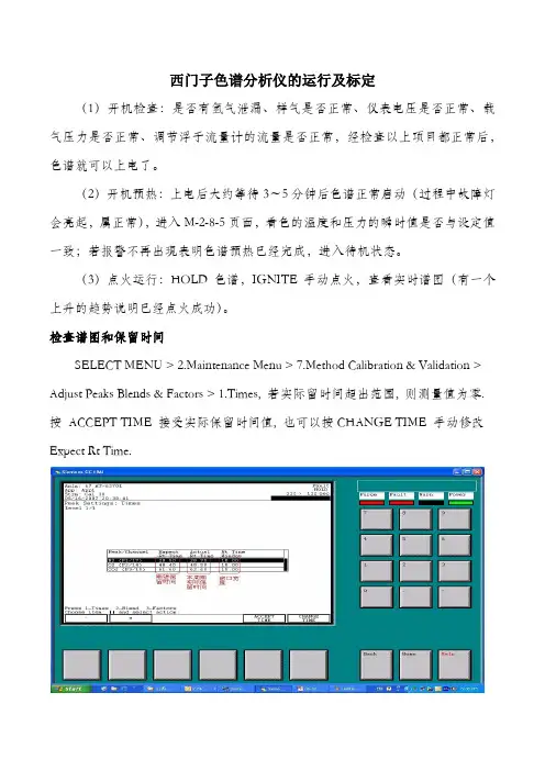
检查谱图和保留时间SELECT MENU > 2.Maintenance Menu > 7.Method Calibration & Validation > Adjust Peaks Blends & Factors > 1.Times, 若实际留时间超出范围, 则测量值为零. 按ACCEPT TIME 接受实际保留时间值, 也可以按CHANGE TIME 手动修改Expect Rt Time.标定仪表在Maintenance Menu, 按7.Method Calibration & Validation > 按NEXT METHOD 选择相应的方法> 3.Adjust Peaks Blends & Factors > 2.Blend > CHANGE BLEND 分别输入每个组份的标准浓度按Home > 7.Method Calibration & Validation > 1.Calibration & Validation > 选择相应的校验流路> START MANUAL > 按Back 退回上一级菜单> 按Run运行> 待周期结束后确认测量无误> 3.Adjust Peaks Blends & Factors > 3-Factors > 按ACCEPT FACTORS 接受新的系数.进入7.Method Calibration & Validation > 1.Calibration & Validation >stop calibration. 等周期完成后,进入测量流路。

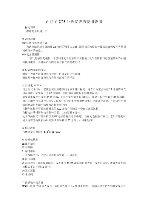
西门子U23分析仪表的使用说明1.标定周期推荐是半年到一年2.测量原理CO-红外气体测量(IR)光谱方法是对非分散性IR辐射的吸收为基础,测量相关波段红外线的衰减幅度即可测量相应气体的浓度;O2-氧含量测量氧气传感器是根据一个燃料池的工作原理来工作的,氧气在阴极与电解液的分界面被转换成电流,并且所产生的电流与氧气浓度成正比3.仪表内部的抽气泵测量一种红外组分和氧气含量,内部是有样气泵的测量两种红外组分和氧气含量内部没有采样泵4.自标定(CAL)当分析仪开始时,它便会使用所连接的介质来进行标定,这个自标定会标定IR通道的零点和灵敏度,如果有一个O2传感器,则它的灵敏度也会同时被标定;如果分析仪表中没有O2传感器,则可用氮气来进行自标定,如果分析仪中装有O2传感器,则只能用空气来进行自标定,根据分析仪的配置来对所提供的介质进行选择,并且这些所提供的介质是不能用软件来进行参数化的在操作过程中可通过面板上的CAL键来手动触发一个自标定的过程自标定持续时间取决于各种因素,大约需要3分钟处于预热模式下的分析仪表(断电后重新启动半小时),自标定会被执行两次,它们开始的时间大约在分析仪启动后的第5分钟和第30分钟(不可避免的)5.标定流量气体流量应保持在1.2~2.0L/min6.分析仪状态M:维护请求F:有故障L:超过极限!:有故障产生,已被记录在日志中并且不再存在R:遥控功能C:功能控制(分析仪被解码,或者通过RS485串行接口来连接,或者自标定,或者大约在预热模式下进行到30分钟)P:泵在运行U:未编码7.面板输入键含意MEAS:测量终止输入操作;退出输入模式(从任何菜单级);从输入模式切换到测量模式并重新给分析仪编码CAL:自标定自动标定:用环境空气与氮气进行标定(处于预热模式时不可用)PUMP:泵启动和停止内部样气泵(如果分析仪处于输入模式时被停止,可以通过MEAS可将泵重新开启)ESC:退出在输入模式中退回到上一级菜单或取消当前输入或取消标定↑:向上箭头增加所选的数值,选择先前的菜单项↓:向下箭头减少所选的数值,选择之后的菜单项→:向右箭头将输入光标向右移一位ENTER:输入在测量模式中, 切换到输入模式在输入模式中,导入已输入的参数或者调用一个菜单项8.分析仪的三种模式预热模式,测量模式,输入模式预热模式:接通电源后仪表自动测试各显示元件,在预热模式过程中会进行一个自标定,自标定气体流量在底行中显示,标定剩余时间在它上面显示,该标定不可中断,大约30分钟进行另外一次自标定,也是预热模式结束;测量模式:分析仪预热结束后进入测量模式输入模式:在测量模式中按“ENTER”进入输入模式,可查看仪表各个参数或者标定和参数化分析仪9.一级菜单分析仪状态:可以调用子菜单,提供分析仪的状态和信息标定:使用标定气体来标定分析仪的零点和灵敏度参数:可以使分析仪的功能满足与应用,改变输入极限、量程和时间常数配置:定义分析仪接口的分配10.分析仪重新编码为了在输入过程完成时让分析仪重新受到密码保护,在测量模式中按下MEAS11.对于ZD----101系统如何进行仪表的手动标定一、一氧化碳零点与氧气量程的校对拔下系统抽气泵入口气管,让系统分析空气,一般待系统稳定分析2~3min左右,,按仪表面板上“CAL”,此时仪表会自动进行自标定过程,显示屏显示倒计时,完成后仪表会显示CO 0.00O2 20.85~21这样该过程了自动完成了氧气的量程与一氧化碳的零点校对此时分析系统应该处于“内控”、“分析”状态,且预处理上的三通切换阀指向“分析”;二、一氧化碳量程校对将系统选择在“内控”、“校对”状态,预处理上的三通切换阀选择在“校对”打开一氧化碳的标气瓶(注意先开总阀,后开减压阀),让仪表测量标气,此时进入仪表菜单ENTER------Calibration(校对)-----Calibr. IR channels(校对IR通道)------Start with range2(开始校对量程2)-----ENTER(确认)即可三、氧气零点校对打开氧气的标气瓶,让仪表测量标气,此时进入仪表菜单ENTER----- Calibration(校对)-----Calibr.O2 sensor(校对氧传感器)-----Staart O2 zero oral(校对氧气零点)-----ENTER(确认)12.针对U23经常出现仪表显示零的问题用户可在ENTER-----Analyzer status(分析仪状态)-----Diagnoatio value(诊断值)-----O2 diagnoatio values(氧气诊断值)此时如果氧气显示负值,需要对氧气的零点进行重新标定即可。
过程检测技术及仪表过程检测在工业生产中起着重要的作用,它可以帮助企业实时监测生产过程,并提供及时的反馈和控制。
过程检测技术及仪表是实现过程检测的关键工具和设备。
本文将介绍几种常见的过程检测技术及仪表,并对其特点和应用进行分析。
1. 传感器技术传感器是过程检测的核心技术之一。
它通过感知物理量或者化学量,并将其转换成电信号或者其他形式的信号,用于监测和测量过程中的各种参数。
常见的传感器技术包括:•温度传感器:用于测量物体的温度变化,广泛应用于工业过程中的温度监测和控制。
•压力传感器:用于测量气体或者液体的压力变化,常见应用于流体管道和储罐的监测。
•液位传感器:用于测量液体的高度或者液位变化,广泛应用于储罐和槽罐中的液位控制。
•流量传感器:用于测量流体流经的速度和流量,常见应用于管道中的流量监测。
•pH传感器:用于测量溶液中的酸碱度,常用于化工和医药行业中的酸碱反应过程监测等。
传感器技术的发展已经取得了重要的进展,从传统的机械式传感器到现代的电子式传感器,传感器的精度和可靠性得到了极大的提高。
同时,随着物联网技术的发展,传感器与云计算和大数据分析相结合,使得过程检测变得更加智能化和高效化。
2. 仪器设备除了传感器技术外,过程检测还需要借助各种仪器设备进行信号的采集、处理和分析。
常见的仪器设备包括:•数据采集仪:用于采集传感器信号,并进行模数转换和信号放大等处理,得到可用的数字信号。
•控制器:用于接收采集到的信号,并根据设定的控制策略进行反馈和控制。
常见的控制器包括PID控制器和PLC控制器等。
•数据分析仪:用于对采集到的数据进行分析和处理,常见的数据分析方法包括统计分析、模型识别和预测等。
•监视器:用于实时监测和显示过程中的各种参数和状态,常见的监视器包括显示屏和报警器等。
仪器设备的综合运用可以帮助企业实现对生产过程的精确监测和控制。
通过合理配置仪器设备,可以实现对生产过程中的各种参数进行实时监测,并根据需要进行调整和优化,实现生产过程的高效和稳定。

FUS080超声波流量计与SIMATIC PDM通信Communication between FUS080 Ultrasonic flow meter and SIMATIC PDM摘要本文详细介绍了如何FUS080菜单的含义、如何与过PDM软件通信、如何修改FUS080参数以及常见故障诊断方法。
关键词 FUS080超声波流量计、PDM、最大流量、脉冲当量、脉冲宽度、管道形状Key Words FUS080 Ultrasonic flow meter, PDM, Maximum flow, Mount per pulse, Pipe GeometricIA&DT Service & Support Page 2-17目录1. 硬件说明 (4)2. DD文件安装 (5)3. FUS080参数修改 (6)4. 故障诊断 (13)IA&DT Service & Support Page 3-171. 硬件说明(1)电池安装:如果带有备用电池,按照下图安装电池;(2)连接脉冲输出56和57为通道A;66和67为通道B;二者均为干接点,需要外接24V(3)菜单说明正向累计流量Totalizer1反向累计流量Totalizer2IA&DT Service & SupportPage 5-17瞬时流量错误代码举例说明:F125表示仪表存在F1, F2 和 F5故障,其含义分别如下:F 没有故障(正常显示)F1 通道1没有正常工作F2 通道1没有正常工作 F3 内部错误 F4 内部错误(详见该文档故障检测部分) F5 电池电量太低 F6 流量超上限 F7 脉冲输出A 超限 F8 脉冲输出B 超限2. DD 文件安装(1)在启动菜单中,找到SIMATIC PDM 文件夹下的Manage device catalog(2)找到FUS080 DD 所在的安装目录文件夹FUS080_MB_DD_01_01_04-006002选择OK即可。
DELLSONICS北京迪妙声科技有限公司BEJING DELLSONICS SCIENCE & TECHNOLOGY LTD.公 司 简 介北京迪妙声科技有限公司(原名北京妙声力科技有限公司),位于北京市海淀区中关村南大街,是与西门子公司德国总部正式签约的西门子过程仪表及分析仪器核心合作伙伴,也是西门子北方区域规模最大、实力最强的优秀代理商。
公司主营:一、西门子-妙声力(Milltronics)系列物位产品:超声波物位计、超声波液位差计、超声波泥水界面计、超声波明渠流量计、雷达物位计、射频导纳物位计、射频导纳油水界面计、;射频导纳物位开关、音叉式物位开关、阻旋式物位开关;皮带称、固体质量流量计、冲板流量计等。
二、西门子过程仪表产品:电磁流量计、质量流量计、超声波流量计、 温度变送器、压力变送器、阀门定位器、气体分析仪等。
三、德国UWT公司的阻旋式料位开关、音叉式料位开关、重锤式料位计等产品。
四、自行研发生产超声波液位计、温度变送器、压力变送器、数显表及油田专用仪器等产品。
成立于 1954 年的西门子-妙声力公司(Milltronics)是世界公认的超声波物位测量领域的领导者,全球最大的超声波物位仪表生产厂家,在超声波、雷达、电容技术领域拥有超过 60 项专利,超声波产品的综合性能指标经美国《控制》杂志评比,其综合性能名列全球第一!作为西门子公司长期稳定的代理商,我公司有着10 余年产品的销售和服务经验,无论从专业技术水平、现货及备件库存量、售后服务质量、仪表维护以及故障产品国内维修能力等方面,都具备显著的优势。
尤其是我公司一流的技术支持和高效率高品质的服务体系,在业界具有很高的知名度。
如果您需要相关的产品,需要咨询技术问题,需要值得信赖的合作伙伴,敬请来电垂询!传真:总机转50谢谢您的合作与支持!Table of ContentsIntroduction (1)SITRANS LU 01 (1)SITRANS LU 01 Features (3)Programmable Features (3)The Manual (4)Specifications (5)Electronics (5)Programmer (6)Transducer (7)Options (7)Cable (7)Safety marking symbols (8)Installation (9)SITRANS LU 01 (9)Location (9)Cable/Conduit Entry Requirements (9)Mounting (10)Transducer Mounting (10)Interconnection (11)Optional SmartLinx Module (13)System Diagram (14)Transducer (14)Temperature Sensor (15)Relays (15)mA Outputs (15)Communication (16)Serial (16)SmartLinx (16)Level System Synchronization (16)Power (17)AC Supply Wiring (17)DC Supply Wiring (17)Programmer (18)Communications Access (18)Programming (19)Display (19)Keypad (20)Program Mode Entry (21)Changing Parameters (21)Parameter Reset Features (22)Parameters Types (22)Programming Security (22)Operation (23)Display in RUN Mode (23)Keypad (24)System Performance Evaluation (25)Performance Test Results (25)Parameter Reference (27)Helpful Hints (27)Parameter Reset Features (28)Programming Security (28)Quick Start (P001 to P007) (29)Application Parameters (32)Volume (P050 to P055) (32)Display and Reading (P060 to P062) (36)Failsafe (P070 to P072) (37)Relays (P100 to P119) (39)Custom Relays (P111 to P113) (42)Independent Relay Setpoints (43)Independent Relay Failsafe (P129) (46)mA Output (P200 to P219) (47)Independent mA Setpoints (P210 and P211) (48)mA Output Limits (P212 and P213) (48)mA Output Trim (P214 to P215) (49)mA Output Failsafe (P219) (50)Standard Data Logging (P300 to P321) (50)Record Temperatures (P300 to P303) (50)Profile Records (P330 to P337) (51)Auto Record ON and OFF Setpoints (P334 to P337) (52)Installation Records (P340 to P342) (54)Range Calibration (P650 to P654) (54)Temperature Compensation (P660 to P664) (57)Rate (P700 to P707) (58)Measurement Verification (P710 to P713) (60)Transducer Scanning (P725 to P729) (62)Display (P730 to P733) (63)Peripheral Communication Support Parameters (P740 to P749) (65)SmartLinx Reserved (750 to 769) (65)Communications (P772) (66)SmartLinx Hardware Testing (66)Echo Processing (P800 to P807) (67)Advanced Echo Processing (P810 to P825) (70)Profile Pointer (P817 to P825) (72)Advanced TVT Adjustment (P830 to P835) (75)Advanced Shot Adjustment (P840 to P852) (78)Test (P900 to P913) (80)Measurement (P920 to P927) (83)Technical Reference (85)Transmit Pulse (85)Echo Processing (85)Echo Processing Displays (Scope Displays, P810) (86)Dolphin Plus Display (86)Distance Calculation (86)Sound Velocity (86)Volume Calculation (87)Universal, Linear (P050 = 9) (87)Universal, Curved (P050 = 10) (88)Maximum Process Speed (88)Application Examples (89)Example 1 - Level Measurement (90)Material Volume (92)Example 2 - Space Measurement (92)Application Assistance (94)Communication Support (94)MT-00 Measurement Message (95)MT-01 Hold Message (96)MT-03 Point Not Scanned (97)Maintenance (98)Unit Repair and Excluded Liability (98)Troubleshooting Guide (99)Measurement Difficulties (100)Flashing LOE Display (100)Fixed Reading (101)Wrong Reading (102)Programming Charts (104)IntroductionSITRANS LU 01Note: The SITRANS LU 01 is to be used only in the manner outlined in thisinstruction manual.The SITRANS LU 01 is an ultrasonic long-range level monitoring system for liquids and solids. SITRANS LU 01 level monitor uses one Siemens Milltronics ultrasonic transducers (ordered separately) to accurately monitor material levels without material contact.The SITRANS LU 01 transmits electronic pulses to each connected ultrasonic transducer.The transducer converts the electronic pulses to ultrasonic pulses which are emitted from the transducer face in a narrow beam. The SITRANS LU 01 measures the time from the pulse emission, to reception of the reflection (echo) from the material. Using the time measured, the SITRANS LU 01 calculates the distance from the transducer face to the material.The distance calculation depends upon the sound velocity within the vessel. When an Echomax transducer is used, variable air temperatures are automatically compensated.For superior air temperature compensation, a Siemens Milltronics TS-3 temperaturesensor may be used for each vessel. A simple calibration feature compensates forThe SITRANS LU 01 uses Siemens Milltronics patented Sonic Intelligence®echoprocessing. Sonic Intelligence provides high measurement reliability, regardless ofchanging conditions within the vessel monitored. By using ultrasonic echo rangingprinciples with Sonic Intelligence and velocity compensation, the SITRANS LU 01provides outstanding measurement accuracy, usually within 0.25% of range.The distance calculation can be converted to space, material level, material volume, or remaining vessel capacity. The reading chosen (and operating data) for each vessel is displayed on the LCD (liquid crystal display).The relays and mA outputs may be used as preset (or programmed as desired) to activate alarms and/or operate remote monitoring equipment and/or process control equipment.With the addition of a Siemens Milltronics Smartlinx ® protocol specific plug-in communications module, the SITRANS LU 01 is compatible with popular industrial control system standards. Supported protocol include PROFIBUS DP, Allen-Bradley®1 Remote I/O, Modbus® RTU, and DeviceNet TM.Programming can be done locally using the portable programmer keypad, or remotely through optional Dolphin Plus software or SmartLinx.•The programmer transmits the keypad entries via infrared link to the SITRANS LU 01, and can be removed when not in use.•Dolphin Plus allows programming either through the RJ-11 port or hardwired via the RS-232/485 communication port.•SmartLinx provides protocol specific hardware and software for interface with popular industrial communication systems.1.Allen-Bradley is a registered trademark of Rockwell Automation. Modbus is aregistered trademark of Schneider Electric. DeviceNet is a trademark of ODVA(Open DeviceNet Vendor Association).The SITRANS LU 01 is typically used to monitor material level in open or closed vessels but can be used in almost any process which requires a distance measurement (within the system range).Refer to Technical Reference Application Examples on page89 for detailed descriptions of some configuration examples to which the SITRANS LU 01 may be applied. SITRANS LU 01 Features•Enclosure:Chemical resistant, light weight, dust tight, liquid tight,easy to work with.•Backlit LCD: Large digits for Reading and programming value displays.Illuminated LCD insures readability under all lightingconditions. Includes custom Graphic Symbols for continuousindication of operating conditions.•Programmer:20 tactile feedback keys for easy access to programmingand operating functions. Magnetic mounting and infraredinterface permit removal on programming completion.•Communications:SmartLinx CompatibleCommunications ready when equipped with an appropriateSiemens Milltronics SmartLinx module.•Dolphin Compatible CommunicationsDolphin Plus is Windows®1-compatible configuration softwareconnected to the unit via the RG-11 port or remote connectionthrough the RS-232 or RS-485 port. The software provides aneasy means for programming, uploading,or downloadingparameters.•Speed:16/32 bit microprocessor at 16.7 MHz clock speed. 1 vessel(point) per second scanning speed capability.•Reliability:Sonic Intelligence ensures all measurements are accurateand reliable. Immune to power interruptions. All programmingis stored indefinitely. Dynamic operating data is retained forone hour and updated immediately on power resumption. Programmable FeaturesThe SITRANS LU 01 is easy to program, yet versatile enough to handle complex level measurement requirements.General Features•Direct Access:Any operator programmable feature may be accessed directly.•Scroll Access:Scroll forward, scroll back, to key features.•Operation:Select level, space, or distance operation.•Material:Liquid or solid; automatically adjusts echo processing with oneentry.1.Windows is a registered trademark of Microsoft Corporation.SpecificationsElectronicsPower•AC model:100/115/200/230 V AC ±15%, 50/60 Hz, 31 VA•DC model:18 to 30 V DC, 25 WEnvironmental•location indoor / outdoor•altitude2000 m max•ambient temperature–20 to 50 °C (–5 to 122 °F)•relative humidity suitable for outdoor (Type 4X / NEMA 4X / IP65 enclosure) •installation category II•pollution degree: 4Scan Points• 1 point per SITRANS LU 01 max.•frequency independentRange•Level Measurement:0.3 m (1 ft) to 60 m (200 ft) max.Accuracy•0.25% of range or 6 mm (0.24"), whichever is greaterResolution•0.1% of program range1 or 2 mm (0.08"), whichever is greaterMemory•EEPROM (non-volatile) no back-up battery requiredProgramming•via removable programmer or optional Dolphin Plus softwareDisplay•custom graphics backlit LCD with 51 mm (2 in) x 127 mm (5 in) viewing area Synchronization:•up to 16 SITRANS LU 01 units can be synchronized together Temperature Compensation•–50 to 150 °C (–58 to 302 °F)•integral temperature sensor in transducer•TS-3 temperature sensor•programmable fixed temperatureTemperature Error•with compensation:0.09% of range•fixed temperature:0.17% / °C deviation from programmed temperature.1.program range is defined as the empty distance to the face of the transducer(P006) plus any range extension (P801).Outputs•relays: 4 alarm/control relays1 form "C" SPDT contact per relay, rated 5 A at 250 V AC,non-inductive•analog: 1 output max.0.1% resolution0-20 or 4-20 mA, scalable750 Ω, isolated, 30V rms Communications (see Options)•SmartLinx compatible•RS-232 / 485 port•Dolphin Plus compatible•proprietary bipolar current loopEnclosure•Type 4X / NEMA 4X / IP65 1•285 mm W x 209 mm H x 92 mm D (11.2" W x 8.2" H x 3.6" D)•polycarbonateWeight• 2.7kg(6lb)Approvals•See device nameplate.ProgrammerAmbient Temperature•–20 to 50 °C (–5 to 122 °F)Keypad•20 keys with tactile feedbackInterface•non-invasive, digital, infra-redEnclosure•general purpose•67 mm W x 100 mm H x 25 mm D (2.6" W x 4" H x 1" D)•ABS plasticWeight•150 g (0.3 lb)1. The use of approved watertight hubs/glands is required for Type 4X / NEMA 4X,IP65 on watertight applications.TransducerCompatible Models•STH and Echomax® series•Refer to the associated instruction manual.OptionsTemperature Sensor•TS-3SmartLinx Modules•Supported protocols: PROFIBUS DPAllen-Bradley®1 Remote I/OModbus® RTUDeviceNet TMDolphin Plus•Windows®-compatible configuration software connected to the unit via infraredComverter linkRefer to associated product documentation.CableTransducer•RG-62 A/U (or equivalent), 365 m (1,200 ft) max.See transducer instructions for short extensions (in grounded metal conduit, separate from other wiring)mA Output•Belden 8760, shielded / twisted pair, 18 AWG (0.75 mm2) or equivalent or Belden 9552, shielded / two twisted pair, 18 AWG (0.75 mm2)•maximum separation 1,500 m (5,000 ft)Synchronisation•Belden 8760, shielded / twisted pair, 18 AWG (0.75 mm2) or equivalentRelays•No shielded cable necessaryTemperature sensor•Belden 8760 shielded / twisted pair, 18 AWG (0.75 mm2) or equivalent•365 m (1,200 ft) per TS-3 maximumRJ11 Link•No shielded cable necessary•maximum length 3 m (10 ft)1.Allen-Bradley is a registered trademark of Rockwell Automation. Modbus is aregistered trademark of Schneider Electric. DeviceNet is a trademark of ODVA(Open DeviceNet Vendor Association).RS-232 Link•Belden 8770, 3 conductor/shielded, 18 AWG (0.75 mm2) or equivalent •maximum separation 15 m (50 ft)RS-485 Link•Belden 8770, 3 conductor/shielded, 18 AWG (0.75 mm2) or equivalent •maximum separation 1200 m (4000 ft)SmartLinx module•refer to the associated instruction manual.Safety marking symbolsInstallationInstallation shall only be performed by qualified personnel, and in accordance with local governing regulations.The following procedure applies to all SITRANS LU 01 level monitor installations. See Application Examples on page89 for additional installation requirements. Also, refer to the instruction manuals of all other equipment connected to the SITRANS LU 01 foradditional installation instructions.SITRANS LU 01LocationRecommended•Ambient temperature is always within -20 to 50 °C (-5 to 122 °F)•SITRANS LU 01 display window is at shoulder level, unless most interaction is through a SCADA system•Easy access for hand programmer is provided•Cable length requirements are minimal•Mounting surface is free from vibration•Leave sufficient room to swing unit lid open and have clear access.• A place for a laptop computer is provided for on-site Dolphin Plus configuration Avoid•Exposure to direct sunlight. (Provide a sun shield to avoid direct sunlight.)•Proximity to high voltage/current runs, contacts, SCR or variable frequency motor speed controllersCable/Conduit Entry RequirementsEnclosure cable/conduit entries may be required for:•Transducers•TS-3 temperature sensor (if used)•mA output (if used)•Relays (if used)•Synchronization (see Interconnection/Level System Synchronization)•Power•Communications:SmartLinx, RS-485, RS-232, bipolar.Note: Transducer cables must be run in a grounded metal conduit, separate fromother wiring, (except TS-3 temperature sensor wiring, if applicable).MountingInspect all cartons and packaging for possible damage during shipment, before removing the SITRANS LU 01 and associated equipment.1.Loosen the 6 enclosure lid (captivated) screws and swing the lid open.2.Remove the 4 Board B mounting screws (outer corners) and remove the circuitboard assembly.3.Drill required holes in the enclosure bottom to meet enclosure cable/conduit entryrequirements.4.Attach the enclosure to the selected mounting surface (use four predrilled screwholes).5.Attach the conduits/cable hubs to the enclosure. (Do not apply undue force.)Transducer MountingObjects near the transducer face cannot be reliably detected. Mount the transducer above the highest material level (away from the nearest monitored object) by the following Nearest Distance .Warnings•Non metallic enclosure does not provide grounding between connections. Use grounding type bushings and jumpers.•This product is susceptable to electrostatic shock. Follow proper grounding procedures.Nearest DistanceTransducer Types0.5 m (1.65 ft)11.This is the recommended minimum distance. However, it can be reduced under certain circum-stances. Please check the appropriate transducer manual for details.ST -H, ST -25, XRS-5, XCT-8, XCT-12, XPS-10, XPS-15, ST -500.66 m (2.17 ft)XPS-30, XPS-400.99 m (3.25 ft)ST -100, LR-21, XLT -30, XLS-30 1.32m (4.33 ft)LR-13, XLT-60, XLS-60InstallationInterconnectionBefore interconnecting system components to the SITRANS LU 01 terminals, verify all components have been installed in accordance with the associated product instruction manuals.Connect all associated equipment cable shields to the SITRANS LU 01 shieldconnections. To avoid differential ground potentials, do not connect cable shields to ground (earth) elsewhere. Insulate or tape cable shields at all shield junctions to prevent ground loops.AC ModelDC ModelInstallationOptional SmartLinx ModuleThe standard SITRANS LU 01 unit may also be enhanced with Siemens Milltronics SmartLinx communication modules that provide an interface to popular industrial communication systems.To change or install SmartLinx module:With power off and SITRANS LU 01 lid opened:1.Remove the 4 LCD card screws and the card itself.2.Remove the one dummy card screw and the card itself.3.Mount the card by mating the connectors and secure the card in place using the two screws provided.4.Wire in the SmartLinx card according to SmartLinx Manual.5.Replace the LCD card and secure in place using the screws removed in Step 1.Note: Refer to the SmartLinx module documentation for any required hardwaresettings prior to replacing the LCD card or closing the SITRANS LU 01 lid.System DiagramTransducerNote: Maximum system capability. Not all components or their maximum quantitymay be required.customer devicecustomer alarm, pump or control deviceDolphin Plus, or customer deviceindustry control system such as PLC or DCS,SCADA, etc.Notes:•Transducer cables must be run in a grounded metal conduit separate from other wiring (except TS-3 temperature sensor wiring, if applicable).•Hazardous voltage present ontransducer terminals during operation.InstallationTemperature SensorRelaysmA OutputsNote: Use TS-3 temperature sensor only.Do not jumper the terminals if TS-3 is not used.to TS-3All relays are certified for use in equipment where the short circuit capacity of the circuits in which they are connected is limited by fuses having ratings not exceeding the rating of the relays.Note: relays areshown in de-energized state.See Specifications for ratings.0/4-20mA isolated output to750Ω maxCommunicationSerialSmartLinxRefer to the appropriate SmartLinx manual for installation and wiring.Level System SynchronizationAvoid mounting the SITRANS LU 01 near another ultrasonic level monitor. Likewise, when more than one monitor is installed within a single plant/facility, ensure the transducer cables of each system are run in separate grounded metal conduits. If this system separation is impractical, or if measurement difficulties are encountered, system synchronization may be required.Synchronize the SITRANS LU 01 with another SITRANS LU 01 1.Mount the level monitors together in one cabinet.2.Ensure the level monitors share a common power (mains) supply, and ground (earth).3.Interconnect the SYNC terminals of the level monitors to be synchronized.Notes:•The communication protocol is automatically detected by the SITRANS LU 01 and shown via LED on the motherboard.•Ground shield at one end only.Note: To synchronize the SITRANS LU 01 with other Siemens Milltronicsultrasonic level monitors, contact Siemens Milltronics or your local distributor.RS-232RS-485RS-232 port 15 m (50ft) maxto customer device,RS-485 port1200 m (4,000 ft) maxInstallationPowerAC Supply Wiring DC Supply WiringNote: Before making the power connection, ensure proper voltage selection. Notes:•The equipment must be protected by a 15 A fuse or circuit breaker in thebuilding installation.• A circuit breaker or switch in the building installation, marked as thedisconnect switch, shall be in close proximity to the equipment andwithin easy reach of the operator.•Never operate the SITRANS LU 01 with the enclosure lid open, or withthe ground (earth) wire disconnected.•Ensure that any associated alarm or control equipment is disconnected until satisfactory operation is verified.Notes: DC terminals shall be supplied from a SELV source in accordance with IEC-1010-1 Annex H.voltage switch shown in the ’OFF’ position. Select appropriate voltage.100/115/200/230 V50 / 60 HzSelect voltage via switch.ProgrammerCommunications Access The hand programmer fits into the docking bay and is kept there with a magnet.Use the hand programmer to change individualparametersCommunications link is through the internal RJ-11 port.ProgrammingProgrammingOperator programmable features are identified by a Point Number and ParameterNumber. The Index refers to the Relay Number as identified by the Index Type indicators. Parameter Numbers have a preset Parameter Value for each Index Number.Program the SITRANS LU 01 to obtain the desired RUN mode operation.DisplayIn PROGRAM mode, the Index Type, Index Number, Parameter Number, and Parameter Value (as well as a variety of other programming information) may be viewed.Note that many indicators are specific to certain programming conditions and therefore, all indicators are not displayed at any given time. Display Segment DescriptionParameter Number the programmable feature the Parameter Value refers to. Index Type see chart belowIndex the relay the Parameter Value refers to.Parameter Value the current value of the Parameter Number for the Index num-ber displayed.Percent indicates the Parameter Value is displayed in percent. Invalid Entry indicates the value entered is questionable. The unit will notaccept values out of range.Auxiliary Function indicates Auxiliary Function access (applies to only someParameter Numbers).Scroll Access Tag indicates the Parameter Value may be scroll accessed. Program Mode indicates PROGRAM mode is accessed.units auxiliary service mode number entry tagKeypadIn PROGRAM mode, use the SITRANS LU 01 programmer keys to perform the identified functions.Program Mode EntryUpon initial power application, the SITRANS LU 01 displays OFF.To enter PROGRAM mode1.Secure the enclosure lid using the 6 captivated screws.2.Place the infrared programmer in the enclosure lid recess.3.PROGRAM mode for an extended period.Changing Parameters1.unit into PROGRAM mode.2.3.After the third digit is entered, the parameter value is shown.that have been changed).4.5.To alter the Parameter Value for all Indices at once, select Index 00.Notes:•Record each Parameter Value alteration on the appropriate Programming Chart for future reference, (especially should complete reprogramming berequired).•If Parameter Value alteration is not permitted, access the Lock parameter (P000) and enter the security code (See Programming Security).Parameter Reset FeaturesOn initial power up, all parameters are at default values. In many cases, when a Parameter Value is altered, associated Parameter Values are automatically altered accordingly. When a Parameter Number is accessed, if the preset Parameter Value displayed is acceptable, no entry is required.To return an operator adjusted Parameter Value to the preset value, with the appropriateTo reset all parameters to preset values, use Master Reset (P999). Parameters TypesView Only ParametersParameter values indicating status only. They cannot be altered.Global ValuesParameter values common to all inputs and outputs on the SITRANS LU 01.When a global parameter is accessed, the index display automatically disappears. When a non-global parameter is accessed, the index display reappears showing the last index number.Parameter IndexingTo set all indexed values for a parameter to the same value, use index 0.Programming SecurityAll operator programming is retained in non-volatile memory, immune to power interruptions. When programming is complete, the programmer may be removed and locked away to prevent inadvertent programming alteration. Use the Lock (P000) parameter to secure the SITRANS LU 01.Note: Perform a Master Reset (P999) if the SITRANS LU 01 was bench tested using arbitrary Parameter Values before system installation, following an EPROM replacement, or whenever complete reprogramming is required.OperationIn RUN mode, the SITRANS LU 01 detects material levels and provides control functions.The SITRANS LU 01 automatically starts in RUN mode when power is applied. Display in RUN ModeIn the RUN mode, the following values and indicators are observed. Many indicators are specific to certain operating conditions and so not all indicators are not displayed at any given time.DisplaySegment DescriptionTransducer the current display linked to transducer measurement.Reading displays the level, space, or distance (flashes error messages, if any).Percent the Reading is in percent.High Alarm indicates level has risen above 80% (and not yet fallen below 75%).Low Alarm indicates level has fallen below 20% (and not yet risen above 25%).Filling Indicator indicates the vessel is filling.Emptying Indicator indicates the vessel is emptying.Bar Graph indicates the absolute (always a positive value) material level from 0 to 100%.Data Out indicates the SITRANS LU 01 is transmitting data to the Peripheral Com-munications terminals.Scanning Indicator indicates point number scannedAuxiliary Reading as selected by the keypad (terminal numbers if transducer or TS-3 is wired wrong).Relay Number indicates the relays programmed for operation.Relay Status indicates the relay is de-energized (alarm is activated).Normal Operation indicates operating conditions are good and the Reading is reliable.Failsafe Operation indicates operating conditions are poor and the Reading may be incor-rect.high alarmOperationKeypadOperationSystem Performance EvaluationFor initial RUN mode entry (or after any programming alteration), do not use the SITRANS LU 01 to operate process control equipment until satisfactory system programming and performance is verified.1.---- may be displayed briefly while the SITRANS LU 01 takes measurements and calculates the Reading.If an alarm symbol is displayed, the corresponding relay is de-energized.(P001).* Objects close to the transducer face (0%) are not detectable.3.Press to observe the mA output value for the Point Number displayed (Auxiliary Reading).* Objects close to the transducer face (4 mA) are not detectable.4.Failsafe Time Left (time left in percent before failsafe activation).Each time a valid measurement is made, this value (Auxiliary Reading) is reset to 100 and begins to fall toward 0 until the next valid measurement is made.If the Failsafe Time Left reaches 0, the SITRANS LU 01 flashes LOE in the Reading display. All associated data is supplied to the Peripheral Communications terminals (27 and 28). Performance Test ResultsMonitor system performance carefully, under all anticipated operating conditions.A.If the SITRANS LU 01 performs exactly as required, copy all Parameter Value alterations to the Programming Charts in the back of this instruction manual. (Altered Parameter Values may be scroll accessed). No further action is required. The SITRANS LU 01 will continue performing reliably, with little or no maintenance.B.If a measurement difficulty is encountered (the LOE display persists after start up), or performance does not meet installation requirements, proceed to the Troubleshooting Guide on page 99.Operation Level Space or Distance*Empty to Full =0 to 100%100 to 0%Operation Level Space or Distance*Empty to Full =4-20 mA 20-4 mA。
西门子CO分析仪操作说明操作指南:西门子CO分析仪1.准备工作a.将分析仪放置在平稳的台面上,确保周围没有其他物体阻挡仪器的正常运行。
b.将电源插头插入交流电源插座,确保电源供应正常。
c.按下仪器背面电源开关,仪器即可开始预热。
2.连接气源a.将标准气体瓶连接至仪器背面的气源接口上。
确保连接牢固,并通过开启气瓶阀门并确定压力表指示正常的方式来检查气源的连接是否正确。
b.在气瓶上旋转阀门或通过仪器上的调节阀来调整气源流量,保证每分钟流量在推荐范围内。
3.设置分析参数a.打开仪器面板上的电源开关,等待仪器预热完毕。
通常预热时间为30分钟左右,仪器上的指示灯将从红色变为绿色。
b.按下面板上的菜单键,进入设置页面。
使用方向键选择参数设置选项,并使用确认键进入相应的设置界面。
c.根据实际需求设置分析参数,如CO浓度单位、测量时间、报警阈值等。
通过方向键和确认键进行选择和确认。
d.设置完成后,按下退出键返回主页面。
4.进行测量a.确保待测样品被加热至稳定温度。
可以通过将样品放置在加热板上进行加热,或者使用独立的加热设备。
b.将样品连接至分析仪上的进样口,确保连接密封良好。
c.按下开始测量键,仪器开始测量待测样品中的CO浓度。
仪器会显示测量结果,并进行报警和记录。
5.分析数据a.仪器可将测量结果保存至内部存储器中。
用户可以通过菜单选项进入数据页面,并使用方向键和确认键选择和查看具体数据。
b.仪器还可以通过串口或USB接口将数据传输至外部设备,如计算机或打印机,以便进一步分析和处理。
6.日常维护a.每次使用后,将样品通路进行清洗,以防止污染物影响测量结果。
b.定期校准仪器,以确保测量结果的准确性。
校准方法可参照仪器说明书。
请注意,在操作仪器时应严格按照仪器说明书和相关安全操作规程进行,以确保人员和设备的安全。
西门子U23分析仪表的使用说明一:分析仪量程的配置分析仪的量程和上位机的量程只有对应起来分析仪显示屏上的检测值和上位机上的显示值才是对应的。
设置步骤如下:1、在测量界面先按一下“Enter”进入下一界面。
2、在新界面选择“Parameters”一项,按一下“Enter”进入下一界面。
3、在新界面输入密码“222”(如果没弹出此界面操作以下步骤即可)。
4、在新界面可通过上下按键切换各个组分并按一下“Enter”进入下一界面进行量程修改。
5、在新界面选择“switchranges”,按一下“Enter”进入下一界面。
6、在新界面的“Actualranges:”一项后面新的分析仪此处为“AR”,应该通过上下按键改为“1”或者“2”,分别对应着量程1和量程2(根据上位机的量程更改或咨询上海湘乾仪器仪表工程师)。
改完按下“Enter”保存后一直按“Esc”退到测量界面即可。
(各个组分都是按照这个方法更改,重复步骤4、5、6即可或咨询上海湘乾仪器仪表工程师)ULTRAMAT23分析仪可应用于烟气排放监测系统以及过程与安全监测。
通过TüV认证的ULTRAMAT23分析仪可按照13.BlmSchV与TALuft中的要求测量CO、NO、SO2和O2。
通过TüV认证的小容许量程:·单组分和双组分分析仪-CO:0~150mg/m3-NO:0~250mg/m3-SO2:0~400mg/m3·三组分分析仪-CO:0~150mg/m3-NO:0~250mg/m3-SO2:0~400mg/m3比上述量程大的所有量程也都是容许的。
ULTRAMAT23红外气体分析仪能够同时测量四种气体组份,及三个红外气体组分(CO、CO2、NO、CH4、R22)以及采用电化学氧电池测量气体中氧浓度。
ULTRAMAT23分析仪技术资料:ULTRAMAT23分析仪由上海湘润仪器仪表限公司----ULTRAMAT23分析仪纯文本菜单提示操作,操作者和维修人员读取信息方便。