Towards molecularly imprinted polymers selective to peptides and proteins. The epitope approach
- 格式:pdf
- 大小:463.94 KB
- 文档页数:12
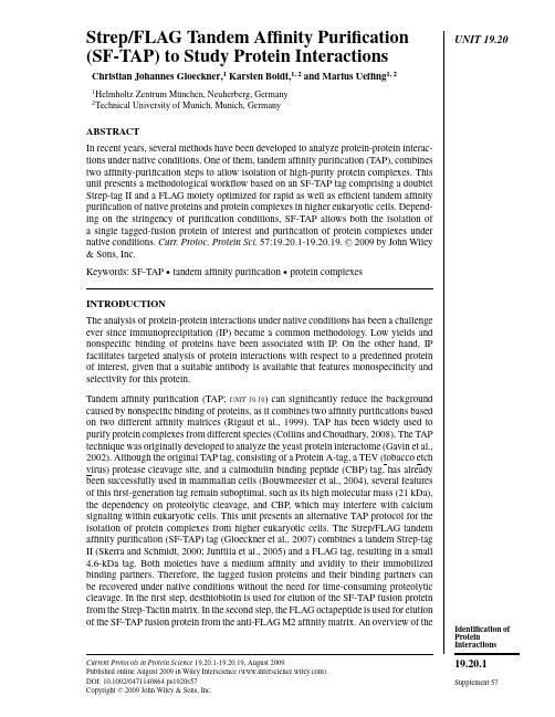
采用TiO2磁珠进行磷酸肽的简单富集Ylva Laurin, Ann-Marie Nissfolk, Johan Öhman, Ulrika Meyer, Helena Hedlund, and Marianne AlbeniusGE Healthcare Bio-Sciences AB, Björkgatan 30, SE-751 84 Uppsala, Sweden介绍磷酸化是一种常见的可逆的翻译后修饰,在细胞信号传导等众多的生物过程中发挥调节作用,因此在肿瘤等许多疾病的研究中具有重要的意义。
对磷酸化的认识有助于我们了解疾病的发生过程。
磷酸蛋白和磷酸肽通常浓度极低,且电离程度差,因此很难通过质谱(MS)进行检测。
本项研究中,我们采用具有顺磁特性的多孔琼脂糖TiO2磁珠作为工具,对模型样品和复杂样品中的磷酸肽进行富集。
实验概况磷酸肽富集步骤本实验需要10 ul的TiO2Mag Sepharose™,磷酸肽的富集通过MagRack 6进行,富集的步骤包括以下四个过程:1.用吸附缓冲液(1 M羟基乙酸,80%乙腈,5%三氟乙酸)进行平衡。
2.上样,混合孵育30min3.分别用1×吸附缓冲液和2×清洗缓冲液进行洗涤(80%乙腈,1%三氟乙酸)。
4.洗脱缓冲液(5%氢氧化铵)对目的肽链进行洗脱。
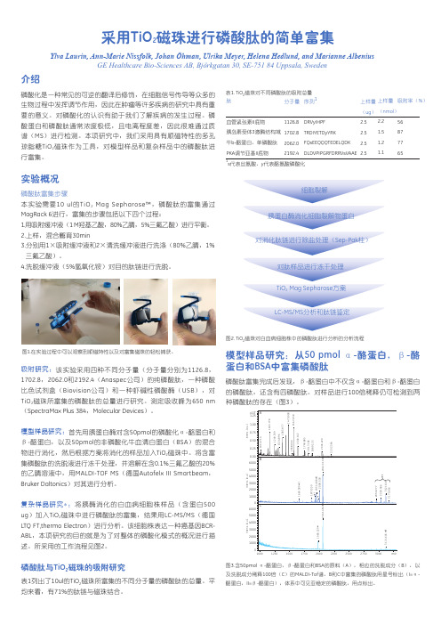
图1.在实验过程中可以观察到顺磁特性以及对富集磁珠的轻松捕获。
吸附研究:该实验采用四种不同分子量(分子量分别为1126.8,1702.8,2062.0和2192.4(Anaspec公司)的纯磷酸肽,一种磷酸比色试剂盒(Biovision公司)和一种虾碱性磷酸酶(USB),对TiO2磁珠所富集的磷酸肽的总量进行研究。
测定吸收峰为650 nm(SpectraMax Plus 384,Molecular Devices)。
模型样品研究:首先用胰蛋白酶对含50pmol的磷酸化α-酪蛋白和β-酪蛋白,以及50pmol的非磷酸化牛血清白蛋白(BSA)的混合物进行消化,然后根据方案将消化的样品加入TiO2磁珠中。
UNIT19.20 Strep/FLAG Tandem Affinity Purification(SF-TAP)to Study Protein InteractionsChristian Johannes Gloeckner,1Karsten Boldt,1,2and Marius Ueffing1,21Helmholtz Zentrum M¨u nchen,Neuherberg,Germany2Technical University of Munich,Munich,GermanyABSTRACTIn recent years,several methods have been developed to analyze protein-protein interac-tions under native conditions.One of them,tandem affinity purification(TAP),combinestwo affinity-purification steps to allow isolation of high-purity protein complexes.Thisunit presents a methodological workflow based on an SF-TAP tag comprising a doubletStrep-tag II and a FLAG moiety optimized for rapid as well as efficient tandem affinitypurification of native proteins and protein complexes in higher eukaryotic cells.Depend-ing on the stringency of purification conditions,SF-TAP allows both the isolation ofa single tagged-fusion protein of interest and purification of protein complexes undernative conditions.Curr.Protoc.Protein Sci.57:19.20.1-19.20.19.C 2009by John Wiley&Sons,Inc.Keywords:SF-TAP r tandem affinity purification r protein complexesINTRODUCTIONThe analysis of protein-protein interactions under native conditions has been a challengeever since immunoprecipitation(IP)became a common methodology.Low yields andnonspecific binding of proteins have been associated with IP.On the other hand,IPfacilitates targeted analysis of protein interactions with respect to a predefined proteinof interest,given that a suitable antibody is available that features monospecificity andselectivity for this protein.Tandem affinity purification(TAP;UNIT19.19)can significantly reduce the backgroundcaused by nonspecific binding of proteins,as it combines two affinity purifications basedon two different affinity matrices(Rigaut et al.,1999).TAP has been widely used topurify protein complexes from different species(Collins and Choudhary,2008).The TAPtechnique was originally developed to analyze the yeast protein interactome(Gavin et al.,2002).Although the original TAP tag,consisting of a Protein A-tag,a TEV(tobacco etchvirus)protease cleavage site,and a calmodulin binding peptide(CBP)tag,has alreadybeen successfully used in mammalian cells(Bouwmeester et al.,2004),several featuresof thisfirst-generation tag remain suboptimal,such as its high molecular mass(21kDa),the dependency on proteolytic cleavage,and CBP,which may interfere with calciumsignaling within eukaryotic cells.This unit presents an alternative TAP protocol for theisolation of protein complexes from higher eukaryotic cells.The Strep/FLAG tandemaffinity purification(SF-TAP)tag(Gloeckner et al.,2007)combines a tandem Strep-tagII(Skerra and Schmidt,2000;Junttila et al.,2005)and a FLAG tag,resulting in a small4.6-kDa tag.Both moieties have a medium affinity and avidity to their immobilizedbinding partners.Therefore,the tagged fusion proteins and their binding partners canbe recovered under native conditions without the need for time-consuming proteolyticcleavage.In thefirst step,desthiobiotin is used for elution of the SF-TAP fusion proteinfrom the Strep-Tactin matrix.In the second step,the FLAG octapeptide is used for elutionof the SF-TAP fusion protein from the anti-FLAG M2affinity matrix.An overview of the Current Protocols in Protein Science19.20.1-19.20.19,August2009Published online August2009in Wiley Interscience().DOI:10.1002/0471140864.ps1920s57Copyright C 2009John Wiley&Sons,Inc.Identification of Protein Interactions19.20.1 Supplement57Strep/FLAGTandem AffinityPurification (SF-TAP)19.20.2Supplement 57Current Protocols in Protein Science A B 1. purification 2. purification binding to Strep-Tactin binding to FLAG matrix elution with desthiobiotin elution with FLAG peptide Key:SF-TAP desthiobiotin FLAG peptide Figure 19.20.1The S trep/FLAG ta n dem affin ity p u rificatio n .(A )N-a n d C-termi n al S F-T AP ta gs (POI,protei n of i n tere s t).(B )Overview of both p u rificatio n s tep s .(1)P u rificatio n by the ta n dem S trep-ta g II moiety:bi n di ng to S trep-T acti n matrix followed by el u tio n with de s thiobioti n .(2)P u rificatio n by the FLAG-ta g moiety:bi n di ng to a n ti-FLAG M2affin ity matrix followed by el u -tio n with FLAG peptide.Abbreviatio ns :s p.,s pecific i n teractor s (s how n a s g ray circle s );n .s p.,n o ns pecific protei ns (co n tami n a n t s ;s how n a s white circle s ).SF-TAP technique and the tag sequence is shown in Figure 19.20.1.The SF-TAP protocol represents an efficient,fast and straightforward purification of protein complexes from mammalian cells within 2hr.This unit describes the full workflow,starting with the cell culture work needed for recombinant expression of the SF-TAP fusion proteins,followed by the SF-TAP protocol (see Basic Protocol 1)and ending with mass spectrometric analysis of the samples (see Basic Protocol 4).Special focus is given to the crucial step of sample preparation for mass spectrometry.For the identification of associated proteins following SF-TAP,the volume of the SF-TAP eluates is reduced by ultrafiltration using centrifugal units with a low molecular weight cut-off or by chloroform/methanol precipitation (see Support Protocol 2).The samples are then directly subjected to proteolytic digestion (see Basic Protocol 2)for analysis on a nano liquid chromatography (LC)–coupled electron sprayIdentification of Protein Interactions 19.20.3Current Protocols in Protein Science Supplement 57Figure 19.20.2Flow chart of a S F-T AP approach i n cl u di ng M S ide n tificatio n of cop u rified pro-tei ns .Thi s figu re co nn ect s all protocol s pre s e n ted i n thi s un it.tandem mass spectrometer.For complex samples,which contain many proteins,an alternative procedure for SDS-PAGE pre-fractionation is provided,including a method for sensitive MS-compatible Coomassie protein staining (see Support Protocol 3)followed by in-gel proteolytic digestion (see Basic Protocol 3).By reducing sample complexity,pre-fractionation helps to increase the number of protein identifications on state-of-the-art LC-coupled tandem mass spectrometers.Representative MS-analysis protocols are provided for an Orbitrap mass spectrometer (Thermo Fisher Scientific),a fast and sensitive system allowing high identification rates from SF-TAP purifications even with low amounts of protein in the sample (see Basic Protocol 4).Finally,a strategy for meta analysis of mass spectrometric data sets using the Scaffold software is provided (see Support Protocol 4).It can generally be used for the analysis of large MS/MS data sets.Figure 19.20.2provides a flowchart of the entire analytical process.Strep/FLAGTandem AffinityPurification (SF-TAP)19.20.4Supplement 57Current Protocols in Protein ScienceBASICPROTOCOL 1STREP/FLAG TANDEM AFFINITY PURIFICATION (SF-TAP)OF PROTEIN COMPLEXES FROM HEK293CELLS A flowchart of the SF-TAP procedure is shown in Figure 19.20.3.Materials HEK293cells (ATCC no.CRL-1573)Complete DMEM containing 10%FBS (APPENDIX 3C )SF-TAP vectors with appropriate insert,and empty control plasmid (see Critical Parameters)Negative control (see annotation to step 3,below)Transfection reagent of choice (see UNIT 5.10)Phosphate-buffered saline (PBS;APPENDIX 2E ),prewarmed Lysis buffer (see recipe)Strep-Tactin Superflow resin (IBA GmbH,cat.no.2-1206-10)Tris-buffered saline (TBS;see recipe)Wash buffer (see recipe)Desthiobiotin elution buffer:dilute 10×buffer E (IBA GmbH,cat.no.2-1000-025)1:10in H 2O (final concentration,2mM desthiobiotin)Anti–FLAG M2agarose (Sigma-Aldrich)FLAG elution buffer (see recipe)14-cm tissue culture plates Cell scraper Millex GP 0.22-μm syringe-driven filter units (Millipore)End-over-end rotator Microspin columns (GE Healthcare,cat.no.27-3565-01)End-over-end rotator Microcon YM-3centrifugal filter devices (Millipore)Additional reagents and equipment for transfection of mammalian cells (UNIT 5.10)Transfect HEK293cells 1.Seed HEK293cells on 14-cm plates at ∼1–2×10⁷cells per dish in complete DMEM medium containing 10%FBS.The amount of cells used for SF-TAP purification can be varied depending on the ex-pression levels of the bait ually,four 14-cm dishes,corresponding to a final amount of ∼4×10⁸HEK293cells,is a good starting point.Strong overexpression of the bait protein usually increases copurification of heat-shock proteins such as HSP70.For in-depth analysis,it is therefore recommended to generate cell lines stably expressing the bait protein.See Support Protocol 1for a stable transfection method.2.Grow cells overnight.3.Transfect cells with the SF-TAP plasmids using a transfection reagent of choice (according to manufacturer’s protocols).HEK293cells can be easily transfected with lipophilic transfection reagents.The trans-fection efficiency is usually >80%.For a typical SF-TAP experiment,1to 4μg plasmid per 14-cm dish is used.Depending on the cell type other transfection reagents may be favorable (also see UNIT 5.10).Although SF-TAP purifications typically exhibit low background caused by nonspecific binding of proteins to the affinity matrix,a suitable negative control should be used in every experiment.Cells transfected with the empty expression vectors may be used in the same amount as for the SF-TAP-tagged bait protein.However,the tag is quite small and expressed at low levels if not fused to a protein.Thus,the untransfected cell line is an acceptable,simple,and inexpensive alternative for a negative control.Identification of Protein Interactions 19.20.5Current Protocols in Protein Science Supplement 571-4 × 10⁸ HEK293 cell s(1-4 co n fl u e n t 14-cm plate s )expre ss i ng S F-TAP f us io n protei nly s i s(15 mi n 4C)vol u mered u ctio nce n trif ug atio n (10 mi n 10,000 × g )a n aly s i sretai n su per n ata n t fi n alel u atei n c u batio n with50 μl/plate S trep-Tacti n matrix (1 hr)el u tio n with200 μl FLAGel u tio n b u ffer(10 mi n )wa s h 3 time s with 500 μl wa s h b u ffer (s pi n 5 s ec, 100 × g )wa s h 3 time s with500 μl wa s h b u ffer(s pi n 5 s ec, 100 × g )el u tio n with 500 μl de s thiobioti n el u tio n b u ffer (10 mi n )i n c u batio n with25 μl/platea n ti-FLAG M2a g aro s e(1 hr)Figure 19.20.3Flow chart for the S F-T AP proced u re.4.Let cells grow for 48hr.If necessary,cells can be starved in DMEM without FBS for 12hr prior to harvesting.Starving might be desirable if cell signaling is to be analyzed,especially prior to differ-ential treatment with growth factors,to eliminate effects of serum growth factors.Lyse cells5.Remove medium from the plates.6.Optional:Rinse cells in warm PBS.Strep/FLAGTandem AffinityPurification (SF-TAP)19.20.6Supplement 57Current Protocols in Protein Science7.Scrape off cells in 1ml lysis buffer per 14-cm plate on ice using a cell scraper,and combine lysates from each experimental condition in a 1.5-ml microcentrifuge tube.8.Lyse cells by incubating 15min on ice with mixing by hand from time to time.9.Pellet cell debris,including nuclei,by centrifuging 10min at 10,000×g ,4◦C.10.Clear lysate supernatant by filtration through a 0.22-μm syringe filter.Perform SF-TAP 11.Wash Strep-Tactin Superflow resin twice,each time with 4resin volumes TBS and once with 4resin volumes lysis buffer.12.Incubate lysates with 50μl per 14-cm plate of settled Strep-Tactin Superflow resin for 1hr at 4◦C (use an end-over-end rotator to keep the resin evenly distributed).Note that a maximum of 200μl settled resin per spin column should not be exceeded.If more than four 14-cm plates (∼4×10⁸HEK293cells)are used,reduce the volume per plate or use additional spin columns in step 13.13.Centrifuge for 30sec at 7000×g ,4◦C,remove the supernatant until 500μl remains,and transfer resin to a microspin column.Snap off bottom closure of the spin column prior to use.The maximum volume of the spin columns is 650μl.Alternatively,centrifugations for wash and elution steps can be performed at room temperature if no cooled centrifuge is available.14.Remove remaining supernatant by centrifugation in the spin column for 5sec at 100×g ,then wash resin three times,each time with 500μl wash buffer (centrifuge 5sec at 100×g each time to remove the supernatant)at 4◦C.Replug spin columns with inverted bottom closure prior to adding the elution buffer in step 15.IMPORTANT NOTE:Do not allow the resin to run dry.Depending on the bait protein,this markedly reduces the yield.15.Add 500μl desthiobiotin elution buffer and gently mix the resin by hand for 10min on ice.16.Remove the plug of the spin column,transfer the column to a new collection tube,and collect the eluate by centrifuging 10sec at 2000×g ,4◦C.If spin columns were closed by the top screw cap during incubation with elution buffer,the cap needs to be removed prior to centrifugation,to allow the pressure to balance out.17.Wash anti–FLAG M2agarose resin three times,each time with 4resin volumes TBS.Suspend resin in TBS and transfer it to microspin columns,then remove the buffer by centrifuging 5sec at 100×g .25μl settled resin per 14-cm plate will be needed.18.Transfer eluate from step 16corresponding to each 14-cm plate to a microspin column containing 25μl settled anti-FLAG M2agarose prepared as in step 17.19.Plug columns,close columns with top screw caps,and incubate for 1hr at 4◦C (on an end-over-end rotator).20.Wash once with 500μl wash buffer,and then twice,each time with 500μl TBS (centrifuge 5sec at 100×g each time to remove the supernatant)at 4◦C.21.For elution,incubate with 4bead volumes (at least 200μl)FLAG elution buffer for 10min,keeping the columns plugged and gently mixing the resin several times.22.After incubation,remove the plugs and top screws of the spin columns,transfer to new collection tubes,and collect the eluate(s)by centrifugation (10sec at 2000×g ).Identification of Protein Interactions 19.20.7Current Protocols in Protein Science Supplement 5723.Depending on downstream method to be used,either precipitate protein (see SupportProtocol 2)or concentrate the eluate by Microcon YM-3centrifugal filter units according to manufacturer’s protocols.SUPPORT PROTOCOL 1GENERATION OF HEK293CLONES STABLY EXPRESSINGSF-TAP-TAGGED PROTEINSIn Basic Protocol 1,SF-TAP-tagged proteins are transiently expressed.However,strong overexpression of the bait protein usually increases copurification of heat-shock proteins such as HSP70.For in-depth analysis,it is therefore recommended to generate cell lines stably expressing the bait protein.This protocol presents a quick method for generating stable HEK293lines.MaterialsHEK293cells (ATCC no.CRL-1573)Complete DMEM containing 10%FBS (APPENDIX 3C )SF-TAP vectors with appropriate insert,and empty control plasmid (see Critical Parameters)Transfection reagent of choice (see UNIT 5.10)Phosphate-buffered saline (PBS;APPENDIX 2E )Complete DMEM medium (APPENDIX 3C )G418(PAA Laboratories, )Freezing solution:90%fetal bovine serum (FBS;Invitrogen)/10%dimethylsulfoxide (DMSO;AR grade)Lysis buffer (see recipe)Blocking reagent:5%(w/v)nonfat dry milk in TBS (see recipe for TBS)containing 0.1%(v/v)Tween 20Anti-FLAG M2antibody (Sigma-Aldrich)10-cm tissue culture dishes12-well and 6-welll tissue culture platesCentrifuge2-ml cryovials (Nunc)Additional reagents and equipment for transfection of mammalian cells (UNIT 5.10),trypsinization and counting of cells (UNIT 5.10),and immunoblotting (UNIT 10.10)Grow and transfect cells1.Grow cells in complete DMEM containing 10%FBS.2.Transfect cells with expression plasmid using a transfection reagent of choice ac-cording to the manufacturer’s protocols.3.Change medium after 6hr.Select cells4.After 48hr,trypsinize and count cells (APPENDIX 3C )and seed them at low density (1×10⁶cells per 10-cm dish)to allow formation of single colonies upon selection.5.Add G418(500to 1000μg/ml)for selection of the SF-TAP expression vectors,which are based on pcDNA3.0and contain a neomycin-resistance gene.6.Grow the cells under G-418selection for 2to 4weeks,changing the medium every second day.7.Collect single colonies with a 200-μl pipet into 12-well plates.8.Keep colonies under G418selection until the cell density is sufficient for expanding them to 6-well dishes (two wells per clone).Strep/FLAGTandem AffinityPurification (SF-TAP)19.20.8Supplement 57Current Protocols in Protein ScienceCryopreserve cells 9.Grow cells to >90%confluency and trypsinize (APPENDIX 3C )one well of each clone for generation of cryostocks.10.Generate cryostocks:a.Wash cells from one well once by adding 3ml PBS,centrifuging 5min at 800×g ,room temperature,and resuspending the pellet in 500μl freezing buffer.b.Transfer resuspended cells to 2-ml cryovials.c.Freeze cells slowly:keep cells for 1hr at −20◦C,then overnight at −80◦C,followed by storage in a liquid nitrogen tank.For cultivation and expansion of confirmed clones,thaw the cryostock at 37◦C,wash cells once with medium,and plate cells onto 10-cm culture dishes.Test for expression of bait protein 11.Lyse one well of each clone in 300μl lysis buffer and test for expression of the bait protein by immunoblotting (UNIT 10.10).SF-TAP proteins can be detected using the anti-FLAG M2antibody (Sigma-Aldrich)at a dilution of 1:1000to 1:5000in blocking reagent.SUPPORTPROTOCOL 2CHLOROFORM/METHANOL PRECIPITATION OF PROTEINS The chloroform/methanol precipitation method described by Wessel and Fl¨u gge (1984)precipitates proteins with high efficiency and yields samples containing low levels of salt contamination.Materials SF-TAP eluate (from Basic Protocol 1)Methanol (AR grade)Chloroform (AR grade)2-ml polypropylene sample tubes 1.Transfer 200μl SF-TAP eluate to a 2-ml sample tube.All steps are performed at ambient temperature.2.Add 0.8ml of methanol,vortex,and centrifuge for 20sec at 9000×g ,room temperature.3.Add 0.2ml chloroform,vortex,and centrifuge for 20sec at 9000×g ,room temperature.4.Add 0.6ml of deionized water,vortex for 5sec,and centrifuge for 1min at 9000×g ,room temperature.5.Carefully remove and discard the upper layer (aqueous phase).The protein precipitate (visible as white flocks)is in the interphase.6.Add 0.6ml of methanol,vortex,and centrifuge for 2min at 16,000×g ,room temperature.7.Carefully remove the supernatant and air dry the pellet.The pellet can be stored for several months at –80◦C.Identification of Protein Interactions 19.20.9Current Protocols in Protein Science Supplement 57BASIC PROTOCOL 2IN-SOLUTION DIGEST OF PROTEINS FOR MASS SPECTROMETRIC ANALYSISThe in-solution digest described here is a quick and efficient method to digest the SF-TAP eluate after protein precipitation (Support Protocol 2).The use of an MS-compatible surfactant helps to solubilize the precipitated proteins.In order to allow the identification of cysteine-containing peptides,random oxidation is prevented,rather than reverted,by applying a DTT/iodoacetamide treatment prior to digestion,leading to a defined-mass adduct.The digested protein sample can then be directly subjected to analysis on an LC-coupled tandem mass spectrometer.MaterialsPrecipitated protein (see Support Protocol 2)50mM ammonium bicarbonate (freshly prepared)RapiGest SF (Waters):prepare 2%(10×)stock solution in deionized water 100mM DTT (prepare from 500mM stock solution;store stock up to 6months at −20◦C)300mM iodoacetamide (prepare fresh)50×(0.5μg/μl)trypsin stock solution (Promega;store at −20◦C)Concentrated (37%)HCl60◦C incubatorPolypropylene inserts (Supelco,cat.no.24722)1to 200μl gel-loader pipet tips (Sorenson Bioscience,/contact.cfm )1.Dissolve the protein pellet in 30μl of 50mM ammonium bicarbonate by extensive vortexing.2.Add 3μl of 10×(2%)RapiGest stock solution (final concentration,0.2%).RapiGest (sodium 3-[(2-methyl-2-undecyl-1,3-dioxolan-4-yl)methoxyl]-1-propanesulfo-nate)is an acid-labile surfactant that helps to solubilize and denature proteins to make them accessible to proteolytic digestion (Yu et al.,2003).3.Add 1μl of 100mM DTT and vortex.4.Incubate 10min at 60◦C.5.Cool the samples to room temperature.6.Add 1μl of 300mM iodoacetamide and vortex.7.Incubate for 30min at room temperature.Samples should be protected from light,since iodoacetamide is light-sensitive.8.Add 2μl trypsin stock solution and vortex.9.Incubate at 37◦C overnight.10.Add 2μl of concentrated (37%)HCl to hydrolyze the RapiGest.For hydrolysis of the RapiGest reagent,the pH must be <2.11.Transfer samples to polypropylene inserts (remove spring).12.Incubate for 30min at room temperature.13.Place inserts in 1.5-ml microcentrifuge tubes and microcentrifuge 10min at 13,000×g ,room temperature.One hydrolysis product of the RapiGest reagent is water-immiscible and can be removed by centrifugation.After centrifugation,it is visible as faint film (oleic phase)on top of theStrep/FLAGTandem Affinity Purification (SF-TAP)19.20.10Supplement 57Current Protocols in Protein Science aqueous sample phase.The other hydrolysis product is an ionic water-soluble component which does not interfere with reversed phase LC or MS analysis.A white pellet might appear.14.Carefully recover the solution between the upper oleic phase and the pellet using gel-loader tips.The sample can now be directly subjected to C18HPLC separation prior to MS/MS-analysis (LC-MS/MS;Basic Protocol 4).Pre-fractionation (Basic Protocol 3)is optional.BASIC PROTOCOL 3PRE-FRACTIONATION VIA SDS-PAGE AND IN-GEL DIGESTION PRIOR TO LC-MS/MS ANALYSIS Pre-fractionation prior to MS analysis increases the number of peptides which can be an-alyzed,and therefore the peptide coverage of identified proteins.This benefit is achieved by overcoming the undersampling problem mainly caused by the limited capacity of the trapping columns used in nano–LC chromatography,or that occurs with high complexity.For these samples,SDS-PAGE pre-fractionation can be used to reduce the complexity.For less complex samples or samples with low protein content,the in-solution digest (Basic Protocol 2)is preferred.Materials Protein sample (e.g.,from Basic Protocol 1or Support Protocol 2)10%NuPAGE gels (Invitrogen)MOPS running buffer (Invitrogen)40%and 100%acetonitrile (AR grade;prepare fresh)5mM DTT (prepare from 500mM stock;store stock up to 6months at −20◦C)25mM iodoacetamide (prepare fresh)Digestion solution:dilute 50×trypsin stock solution (0.5μg/μl,Promega)1:50in 50mM ammonium bicarbonate (freshly prepared)1%and 0.5%(v/v)trifluoroacetic acid (TFA;prepare fresh from 10%v/v stock)50%(v/v)acetonitrile/0.5%(v/v)TFA (prepare fresh)99.5%(v/v)acetonitrile/0.5%(v/v)TFA (prepare fresh)2%(v/v)acetonitrile/0.5%(v/v)TFA Concentration units (e.g.,Microcon from Millipore)Scalpel Polypropylene 96-well microtiter plate:polystyrene material should be avoided since,depending on the product,polymers can be extracted from plastics which produce strong background signals in mass spectrometry 60◦C incubator or heating block Polypropylene 0.5-ml reaction tubes Microtiter plate shaker (e.g.,V ortex mixer equipped with microtiter-plate adaptor)HPLC sample tubes Additional reagents and equipment for SDS-PAGE (UNIT 10.1)and colloidal Coomassie blue staining of gels (Support Protocol 3)Prepare samples 1.Concentrate samples using concentration units (e.g.,Microcon).2.Supplement samples with Laemmli loading buffer (SDS-PAGE loading buffer;UNIT 10.1).A detailed description of the SDS gel electrophoresis and standard buffers can be found in UNIT 10.1or in the protocols supplied with the NuPAGE system.Identification of ProteinInteractions19.20.11Perform electrophoresis and stain gels3.Separate samples on 10%NuPAGE gels according to the manufacturer’s protocols,using MOPS running buffer.4.Stop electrophoresis after the gel front has travelled 1to 2cm.5.Stain gels with colloidal Coomassie blue (see Support Protocol 3).Avoid strong staining of the bands since it increases the time necessary for destaining.6.Excise desired gel pieces with a clean scalpel (three to ten slices,depending on the complexity of the sample).Destain and process gel slices7.Transfer gel pieces into individual wells of a 96-well plate.8.Wash by adding 100μl water to each well and incubating for 30min.9.For destaining:a.Wash twice,each time by incubating the gel slices for 10min in 100μl/well of 40%acetonitrile.b.Wash for 5min in 100μl/well of 100%acetonitrile (if gels are still blue,repeat de-staining).10.Add 100μl of 5mM DTT,then incubate 15min at 60◦C in an incubator or heatingblock.11.Remove DTT solution and cool the plate to room temperature.12.Add 100μl per well of freshly prepared 25mM iodoacetamide,then incubate 30minin the dark.13.Wash twice,each time for 10min with 100μl/well of 40%acetonitrile.14.Wash 5min with 100μl/well of 100%acetonitrile.15.Discard supernatant and air dry (or SpeedVac)the gel pieces to complete dryness.Digest and extract gel slices16.Add 20to 30μl per well of freshly prepared digestion solution (depending on the sizeof the gel plugs).Wrap plates in Parafilm to reduce evaporation during the overnight incubation (or use a humidified incubator in step 17).17.Digest overnight at 37◦C.18.For extraction of the peptides from the gel piece,add 10μl 1%TFA,then shake15min on a V ortex mixer with a microtiter plate adapter.The peptides are extracted in three steps with increasing acetonitrile concentrations (steps 18to 23).19.Transfer liquid (extract 1)to a 0.5-ml polypropylene tube.20.Add 50μl 50%acetonitrile/0.5%TFA to the gel piece and shake 15min on a V ortexmixer with a microtiter plate adapter.21.Remove the liquid (extract 2)and pool extracts 1and 2.22.Add 50μl 99.5%acetonitrile/0.5%TFA to the gel piece,then shake 15min on aV ortex mixer with a microtiter plate adapter.23.Remove the liquid (extract 3)and pool extract 3with 1and 2.Strep/FLAG Tandem AffinityPurification(SF-TAP)19.20.1224.Dry samples to complete dryness in a SpeedVac evaporator.25.Redissolve samples in50μl of2%acetonitrile/0.5%TFA by shaking(e.g.,on aV ortex mixer)for10to15min,then transfer the sample into HPLC sample tubes for LC-MS/MS analysis.SUPPORT PROTOCOL3QUICK MS-COMPATIBLE COLLOIDAL COOMASSIE STAIN OF PROTEINS AFTER SDS-PAGE SEPARATIONThe colloidal Coomassie stain(Kang et al.,2002)represents a fast and sensitive MS-compatible protein staining method.In contrast to the classical staining protocol,no intense and time-consuming destaining is needed to visualize protein bands.Therefore, this method is ideal for a quick staining of the protein bands and provides good orientation on how the gel can be fractionated without splitting predominant bands(see Basic Protocol3).MaterialsElectrophoresed SDS gel containing protein samples of interest(e.g.,from Basic Protocol3)Colloidal Coomassie staining solution(see recipe)Destaining solution:10%(v/v)ethanol/2%(v/v)orthophosphoric acidGel staining trays of appropriate size1.Wash gels twice,each time for10min in deionized water in a staining tray.The SDS must be removed before staining to reduce background signals.2.Incubate gels for10min in colloidal Coomassie staining solution.The incubation steps are kept short for the staining of gels used for pre-fractionation.The staining can be prolonged up to overnight.The maximum staining will be reached after ∼3hr incubation in the staining solution.3.Incubate gels for10min in destaining solution.4.Wash gels twice,each time for10min in deionized water.BASIC PROTOCOL4LC-MS/MS ANALYSIS OF DIGESTED SF-TAP SAMPLESThe following protocol describes MS analysis of digested protein samples on an LC-coupled ESI tandem mass spectrometer.The representative MS-analysis protocol is provided for an Orbitrap mass spectrometer(Thermo Fisher Scientific).The Orbitrap system combines fast data acquisition with high mass accuracy and is therefore ideal for the analysis of SF-TAP samples.Background information on mass spectrometric analysis can be found in UNIT16.11.MaterialsDigested protein sample,either from in-solution digest(Basic Protocol2)or in-gel digest(Basic Protocol3)Nano HPLC loading buffer:0.1%formic acid in HPLC-grade waterNano HPLC buffer A:2%acetonitrile/0.1%formic acid in HPLC-grade waterNano HPLC buffer B:80%acetonitrile/0.1%formic acid in HPLC-grade water HPLC vials(Dionex)Nano HPLC system(UltiMate3000,Dionex)equipped with a trap column (100μm i.d.×2cm,packed with Acclaim PepMap100C18resin,5μm,100◦A;Dionex)and an analytical column(75μm i.d.×15cm,packed with AcclaimPepMap100C18resin,3μm,100◦A;Dionex)Mass spectrometer:Oritrap XL with a nanospray ion source(ThermoFisher Scientific;also see UNIT16.11)。

A Method for the Rapid and Efficient Elution of NativeAffinity-Purified Protein A Tagged ComplexesCaterina Strambio-de-Castillia,†Jaclyn Tetenbaum-Novatt,†Brian S.Imai,‡Brian T.Chait,§andMichael P.Rout*,†The Rockefeller University,1230York Avenue,New York New York 10021-6399Received May 24,2005A problem faced in proteomics studies is the recovery of tagged protein complexes in their native and active form.Here we describe a peptide,Bio-Ox,that mimics the immunoglobulin G (IgG)binding interface of Staphylococcus aureus Protein A,and competitively displaces affinity-purified Protein A fusion proteins and protein complexes from IgG-Sepharose.We show that Bio-Ox elution is a robust method for the efficient and rapid recovery of native tagged proteins,and can be applied to a variety of structural genomics and proteomics studies.Keywords:Staphylococcus aureus •Protein A •affinity purification •proteomics •fusion proteinIntroductionProtein -protein interactions are central to the maintenance and control of cellular processes.The study of such protein -protein interactions has been greatly enhanced by fusion protein technology,wherein specific peptide or protein domain “tags”are fused to the protein of interest (generally at either its carboxyl-terminus or amino-terminus).These tags can facilitate the detection,increase the yield,and enhance the solubility of their associated proteins.1-3Most importantly,these fusion domains have been exploited to allow the single-step purification of the test protein either alone or in complexes with its in vivo binding partners.4-6The yield of these purifica-tion methods is often high enough to allow the identification of such binding partners by mass spectrometry.A commonly used affinity tagging method generates ge-nomically expressed Protein A (PrA)fusion proteins by modify-ing the coding sequence of the protein under study via PCR-directed approaches.7-9This method takes advantage of the ∼10nM binding affinity of PrA from S taphylococcus aureus for the constant region (Fc)of immunoglobulin G (IgG).10After purification on IgG-conjugated resins,PrA-tagged proteins or protein complexes are most commonly eluted from the resin using high or low pH conditions.These elution methods typically lead to the denaturation of the isolated proteins,the dissociation of complexes,and concomitant loss of activity.However,it is often desirable to recover soluble native protein or protein complexes.One method by which this can be achieved is by constructing a cleavable tag.Such tags carry a specific cleavage site for a protease placed proximal to the tagged protein,allowing the tag to be removed from the fusion protein.Proteases that are widely used for this purpose includeblood coagulation factors X (factor Xa),enteropeptidase (en-terokinase),alpha-thrombin,and the tobacco etch virus (TEV)protease.Nevertheless,this method has drawbacks.First,the literature is replete with reports of fusion proteins that were cleaved by these proteases at sites other than the canonical cleaving site.11-14Second,the removal of the tag destroys the ability to detect or further purify the protein of interest,necessitating the encumbrance of a second,tandem tag.15Here,we describe a rapid single step method for the efficient recovery of native and active PrA fusion proteins and protein complexes from IgG-Sepharose.This technique avoids the complications of having to use a protease and in addition has the advantage of retaining the original tag on the target protein after elution,permitting further purification steps and detection of the fusion protein in subsequent experiments.Our method takes advantage of a previously described peptide,termed FcIII,16which mimics the protein -protein binding interface of PrA for the hinge region on the Fc domain of human IgG.We modified FcIII by the addition of a biotin moiety to its amino-terminus to increase the peptide’s solubility while leaving its affinity for Fc intact s making it a more effective elution reagent.We termed this modified peptide,Bio-Ox.To investigate the properties of Bio-Ox,PrA-tagged proteins were isolated in their native state from yeast on an IgG-conjugated Sepharose resin,either alone or in combination with their in vivo interacting partners;the Bio-Ox peptide was then used to competitively displace the tagged proteins and elute them from the resin.The efficiency of elution was monitored by quantitatively comparing the amounts of proteins eluted to the amounts remaining on the resin under a variety of test conditions.We show that Bio-Ox elution is a robust method for the efficient and rapid recovery of native tagged proteins that can be applied to a variety of structural genomics and proteomics studies.*To whom correspondence should be addressed.Tel:+1(212)327-8135.E-mail:rout@.†Laboratory of Cellular and Structural Biology,Box 213.‡Proteomics Resource Center,Box 105.§Laboratory of Mass Spectrometry and Gaseous Ion Chemistry,Box 170.2250Journal of Proteome Research 2005,4,2250-225610.1021/pr0501517CCC:$30.25©2005American Chemical SocietyPublished on Web10/08/2005Experimental SectionPeptide Synthesis,Oxidation and Cyclization.Peptides were synthesized using standard Fmoc protocols.Typical deprotec-tion times with20%piperidine were2times10min and typical coupling times with4-10-fold excess of amino acids over resin were2to6h.Small batches of peptides were made on a Symphony synthesizer(Protein Technologies,Inc.),while larger batches were made manually.Peptides were cleaved from the resin using94.5%trifluoroacetic acid, 2.5%water, 2.5% ethanedithiol and1%triisopropylsilane for3h at25°C.The solubilized peptides were precipitated with10volumes of cold tert-butyl methyl ether and the precipitated peptide was washed several times with ether prior to air-drying.The air-dried peptide was dissolved in20%acetonitrile in water to approximately0.5mg/mL,the pH was adjusted to8.5using sodium bicarbonate and the peptide was allowed to air oxidize overnight to promote cyclization.The progress of cyclization was monitored by mass spectrometry.The cyclized crude peptide was purified using standard preparative reversed phase HPLC using a Vydac218TP1022C18column.Peptide Solubility.Eluting peptides were suspended at a concentration of440µM(0.77mg/mL for BioOx;0.67mg/mL for FcIII),in peptide buffer by extensive vortexing.The peptide concentration was verified by measuring the OD280nm of each solution(extinction coefficient:1OD280nm)0.13mg/mL).The peptide solutions/suspensions were then combined with equal amounts of a100mM buffer to obtain∼220µM peptide at a range of pH values(buffers:Na-Acetate pH4.8,Na-Citrate pH 5.4,Na-Succinate pH5.8,Na-MES pH6.2,BisTris-Cl pH6.5, Na-HEPES pH7.4,Na-TES pH7.5,Tris-Cl pH8.3,Na-CAPSO pH9.6).Samples were incubated at room temperature with gentle agitation for20min,and then insoluble material was removed by centrifugation at21000×g max for20min at25°C.The concentration of peptide in each remaining superna-tant was determined by measuring its OD280nm.To determine the maximum solubility of each peptide,the peptides were dissolved to saturation in peptide buffer by extensive vortexing and incubation with stirring at25°C overnight.Insoluble material was removed by centrifugation at15000×g for15min at25°C and the amount of dissolved peptide was measured directly by amino acid analysis.Peptide Competitive Displacement of Bound Recombinant PrA from IgG-Sepharose.Recombinant PrA(280µg;6.7nmol) from S.aureus(Pierce)was dissolved in1mL TB-T[20mM HEPES-KOH pH7.4,110mM KOAc,2mM MgCl2,0.1%Tween-20(vol/vol)]and added to280µL of packed pre-equilibrated Sepharose4B(Amersham Biosciences)conjugated with affinity-purified rabbit IgG(ICN/Cappel; 1.87nmoles IgG).After incubation on a rotating wheel overnight at4°C,the resin was washed twice with1mL TB-T,twice with1mL TB-T containing 200mM MgCl2,and twice with1mL TB-T.After the final wash, the resin was divided evenly into14equal aliquots.The peptide was dissolved in peptide buffer at concentrations ranging between0and440µM peptide.Aliquots of400µL of the appropriate peptide solution was added to each PrA-IgG-Sepharose containing tube,and the tubes were then incubated on a rotating platform for3h at4°C followed by1h at25°C. After displacement of bound PrA from the IgG-Sepharose,the resin was recovered by centrifugation on a Bio-Spin column (BioRad),and resuspended in one-bed volume of sample buffer.Samples were separated by SDS-PAGE.Yeast Strains.Strains are isogenic to DH5alpha unless otherwise specified.All yeast strains were constructed using standard genetic techniques.C-terminal genomically tagged strains were generated using the PCR method previously described.7,17Affinity Purification of Proteins and Protein Complexes on IgG-Sepharose.The protocol for the purification of PrA-containing complexes was modified from published methods.18-20For the purification of Kap95p-PrA,yeast cytosol was prepared essentially as previously described.21,22Kap95p-PrA cytosol was diluted with3.75volumes of extraction buffer 1[EB1:20mM Hepes/KOH,pH7.4,0.1%(vol/vol)Tween-20, 1mM EDTA,1mM DTT,4µg/mL pepstatin,0.2mg/mL PMSF]. The diluted cytosol was cleared by centrifugation at2000×g av for10min in a Sorvall T6000D tabletop centrifuge and at 181000×g max for1h in a Type80Ti Beckman rotor at4°C.10µL bed volume of IgG-Sepharose pre-equilibrated in EB1was added per0.5mL of cytosol and the binding reaction was incubated overnight at4°C on a rotating wheel.The resin was recovered by centrifugation at2000×g av for1min in a Sorvall T6000D tabletop centrifuge,transferred to1.5mL snap-cap tubes(Eppendorf),and washed6times with EB1without DTT. For the purification of Nup82p-PrA,cells were grown in Whickerham’s medium21to a concentration of4×107cells/ mL,washed with water and with20mM Hepes/KOH pH7.4, 1.2%PVP(weight/vol),4µg/mL pepstatin,0.2mg/mL PMSF, and frozen in liquid N2before being ground with a motorized grinder(Retsch).Ground cell powder(1g)was thawed into10 mL of extraction buffer2[EB2;20mM Na-HEPES,pH7.4,0.5% TritonX-100(vol/vol),75mM NaCl,1mM DTT,4µg/mL pepstatin,0.2mg/mL PMSF].Cell lysates were homogenized by extensive vortexing at25°C followed by the use of a Polytron for25s(PT10/35;Brinkman Instruments)at4°C.Clearing of the homogenate,binding to IgG-Sepharose,resin recovery and washing was done as above except that10µL of IgG-Sepharose bed volume was used per1g of cell powder and EB2without DTT was used for all the washes.Elution of the PrA tagged complexes was performed as described below.Peptide Elution of Test Proteins and Protein Complexes and Removal of Peptide by Size Exclusion.Kap95p-PrA or Nup82p-PrA bound IgG-Sepharose resin was recovered over a pre-equilibrated Bio-Spin column(BioRad)by centrifugation for1min at1000×g max.Three bed-volumes of440µM(unless otherwise indicated in the text)of eluting peptide in peptide buffer were added per volume of packed IgG Sepharose resin. The elution was carried out for various times(as indicated in the text)at either4°C or at25°C.When elution was complete, the eluate was recovered over a Bio-Spin column.Finally,the resin was washed with one bed-volume of elution buffer to displace more eluted material from the resin and the wash was pooled with the initial eluate.The peptide was removed by filtration of the eluate over a micro spin G25column(Amer-sham Biosciences)as described by the manufacturer.Kap95p-Nup2p in Vitro Binding Experiments.To demon-strate in vitro binding of proteins after elution from the resin, Kap95p-PrA from0.3mL of yeast cytosol was affinity-purified on17.5µL of packed IgG-Sepharose and eluted with52.5µL of440µM Bio-Ox for2.5h at4°C followed by1h at25°C. The resulting sample(total volume88µL)was mixed with0.1µL of E.coli total cell lysate containing Nup2p-GST(generous gift from David Dilworth and John Aitchison23)and brought to a total volume of500µL with TB-T,1mM DTT,4µg/mL pepstatin,0.2mg/mL PMSF.Controls were set up in the absence of either Kap95p-PrA or Nup2p-GST.The samples were incubated at25°C for30min after which40µL of packed,pre-Native Elution of PrA-Tagged Proteins research articlesJournal of Proteome Research•Vol.4,No.6,20052251equilibrated glutathione-Sepharose 4B resin (Amersham Bio-sciences)was added per sample and the incubation was continued at 4°C for 1h.After nine washes with 1mL of TB-T,1mM DTT,4µg/mL pepstatin,0.2mg/mL PMSF,at 25°C,the resin was recovered on Bio-Spin columns as described above and bound material was eluted with 40µL of sample buffer.The samples were resolved on SDS-PAGE alongside an aliquot of input peptide-eluted Kap95p-PrA.To demonstrate the recovery of in vitro reconstituted protein complexes from the resin,Kap95p-PrA from 0.3mL of yeast cytosol was affinity-purified on 10µL of packed IgG-Sepharose and the washed resin was equilibrated in TB-T,1mM DTT,4µg/mL pepstatin,0.2mg/mL PMSF.This pre-bound Kap95p-PrA was mixed with 50µL of E.coli total cell lysate containing Nup2p-GST in a total volume of 1mL of TB-T,1mM DTT,4µg/mL pepstatin,0.2mg/mL PMSF.A mock control experiment was set up in the absence of Nup2p-GST.The binding reaction was carried out for 1h at 4°C and the resin was washed 2times with 1mL of TB-T,2times with 1mL of TB-T containing 100µM ATP and 3times with peptide buffer (all washed were without DTT).Bound material was eluted with 30µL of 440µM Bio-Ox in peptide buffer at 4°C for 2.5h at 4°C followed by 1h at 25°C.Samples were resolved by SDS-PAGE.Figure 1.Addition of a Biotin moiety to the FcIII peptide does not alter the ability of the peptide to competitively displace bound PrA from IgG-Sepharose.(a)Primary sequence and chemical structure of the biotinylated FcIII peptide,Bio-Ox.(b)220µM suspensions of peptides were prepared in buffers of different pHs,and allowed to solubilize.The material remaining in the buffer after centrifugation is plotted for Bio-Ox (closed triangles,black trend line )and FcIII (open circles,gray trend line ;dashed horizontal line represents the starting 220µM level .(c)Increasing amounts of Bio-Ox (closed triangles )and FcIII (open diamonds )were used to competitively displace recombinant PrA from IgG-Sepharose.The amounts of PrA left on the resin after elution were resolved by SDS-PAGE alongside known amounts of PrA standards.The data are displayed on logarithmic scale on both axes.Data are displayed as a %recovery relative to the input PrA amount (i.e.,PrA amount remaining bound in the absence of eluting peptide).Linear regression for both data sets was used to calculate the IC50.research articlesStrambio-de-Castillia et al.2252Journal of Proteome Research •Vol.4,No.6,2005Quantitation and Image Analyses.Band intensities were quantified with the Openlab software (Improvision),and the data was plotted using Excel (Microsoft).Results and DiscussionDesign of the PrA Mimicking Peptide.The hinge region on the Fc fragment of immunoglobulin G (IgG)interacts with Staphylococcus aureus Protein A (PrA).This region was also found to be the preferred binding site for peptides selected by bacteriophage display from a random library.16The specific Fc binding interactions of a selected 13amino acid peptide (termed FcIII),were shown to closely mimic those of natural Fc binding partners.We reasoned that this peptide could be used to efficiently displace PrA tagged proteins from IgG-conjugated affinity resins.Initial trials with FcIII determined that,although it functioned as an eluant,it exhibited a strong tendency to aggregate and its solubility under physiological conditions was not sufficient for many practical purposes,leading to low yields and nonreproducible results.As the high peptide concentrations needed for elution are outside the conditions for which the FcIII peptide was designed,we synthesized several modified peptides based on FcIII,with the specific aim of increasing their solubility and decreasing their degree of aggregation under conditions that would be useful for the isolation of proteins and protein complexes.Among the different alternatives,the most efficient in the displacement of bound PrA-tagged Kap95p from IgG-Sepharose was a peptide in which the amino-terminus of the original FcIII peptide wasFigure 2.Bio-Ox can be used to efficiently compete bound PrA-tagged proteins and protein complexes from IgG-Sepharose in a temperature-dependent fashion.(a )Kap95p-PrA/Kap60p was affinity-purified on IgG-Sepharose from logarithmically growing yeast cells.440µM Bio-Ox was used to competitively displace the bound tagged proteins from the IgG-Sepharose resin.The elution reaction was carried out for the times indicated.At the end of the incubation time eluted proteins (E )and proteins remaining bound to the resin (B )were resolved on SDS-PAGE.(b )Kap95p-PrA (closed squares)and Nup82p-PrA (open squares )were affinity-purified on IgG-Sepharose from logarithmically growing yeast cells and eluted as described above.The amounts of eluted versus resin-bound protein was quantified using the OpenLab software and the elution efficiency for each time point is presented as the percentage of eluted material over the total amount of bound plus eluted material (%eluted).(c )440µM Bio-Ox was used to elute Kap95p-PrA or Nup82p-PrA for 1h at 4°C or 25°C as indicated.Native Elution of PrA-Tagged Proteinsresearch articlesJournal of Proteome Research •Vol.4,No.6,20052253modified by the addition of a Biotin moiety (data not shown).We termed this peptide Bio-Ox (Figure 1,panel a).The solubility of Bio-Ox was measured directly by amino acid analysis and was shown to be ∼3-fold greater than the solubility of FcIII at pH 7.4.In addition,comparison of the solubility of both peptides over a range of pHs indicated that the Bio-Ox was considerably more soluble than FcIII at all but the most extreme pHs tested;importantly,Bio-Ox is very soluble across the full physiological range of pHs (Figure 1,panel b).To determine whether the addition of the Biotin moiety could have altered the inhibiting ability of the peptide,we measured the inhibition constant for Bio-Ox and found it to be comparable with the reported K i for FcIII (∼11nM;data not shown).We then measured the IC 50for competitive displacement for FcIII and Bio-Ox,under conditions in which both were soluble.For this test,commercially available recom-binant PrA from S.aureus was first bound to IgG-Sepharose and then increasing concentrations of the peptide were used to displace the bound PrA from the immobilized IgG (Figure 1,panel c).The apparent IC 50was found to be 10.4(3.2µM for FcIII and 9.8(2.6µM for Bio-Ox (mean value of four independent trials (standard deviation of the mean).Taken together,Bio-Ox appears to be as efficient as FcIII at binding to the F c portion of antibodies and competing for this site with Protein A,but is far more soluble in physiologically compatible buffers,a key requirement for an efficient elution peptide (Figure 3).Experimental Design of the Competitive Elution Procedure.The principle of the method is as follows;genomically PrA-tagged proteins of interest are expressed in yeast and affinity isolated on IgG-conjugated Sepharose resin.Depending on the conditions used for lysis and extraction,the test protein can be recovered in native form either in isolation or in complexes with protein partners.After binding,the resin is recovered by centrifugation and washed extensively to remove unbound material.The bound material is competitively displaced from the IgG-Sepharose resin by incubation with 440µM Bio-Ox peptide in peptide buffer for 2h at 4°C.Finally,the peptide is rapidly (<1min)removed from the eluted sample by fraction-ation over a size exclusion spin column.Given a typical protein of average abundance,1-10µg of pure protein can be recovered from 1g of cells using this method.Figure 3.Elution of Kap95-PrA/Kap60p is dose dependent.(a )Kap95p-PrA was affinity-purified on IgG-Sepharose from loga-rithmically growing yeast cells and eluted using increasing concentrations of Bio-Ox peptide as indicated.(b )The elution efficiency measured as described in Figure 2was plotted versus the peptide concentration in logarithmic scale as indicated.Figure 4.Eluted Kap95p-PrA/Kap60complex retains its biological activity.(a )Kap95p-PrA was prepared by affinity purification followed by Bio-Ox peptide elution (Kap95-PrA eluate ).Three binding reactions were then set up containing eluted Kap95p-PrA and Nup2p-GST bacterial lysate,Kap95p-PrA alone or Nup2p-GST alone.At the end of the incubation,Nup2p-GST was affinity-purified on glutathione-Sepharose and the immobilized material was eluted from the resin with sample buffer and resolved on SDS -PAGE (GST bound ).(b )Kap95p-PrA was immobilized on IgG-Sepharose and incubated with (+)or without (-)bacterial lysate containing Nup2p-GST.The resulting material was eluted using Bio-Ox.Eluate (E )and resin bound (B )material was resolved on SDS-PAGE.*,indicates a Nup2p breakdown product.Table 1.Elution Efficiency for PrA Tagged Nupsname of nup%yieldNup53p 56Nup59p 81Nup84p 88Nup85p 81Nic96p 76Nsp1p 99Nup1p 99Nup120p 69Nup157p 82Nup159p 53Nup170p 80Nup192p 76Gle2p 90research articlesStrambio-de-Castillia et al.2254Journal of Proteome Research •Vol.4,No.6,2005To explore the characteristics of Bio-Ox elution under conditions that preserve native protein complexes,we chose to work with the yeast karyopherin Kap95p-PrA/Kap60p com-plex,24and with the yeast nucleoporin Nup82p-PrA/Nsp1p/ Nup159p complex.25,26This choice was dictated by our interest in the structure and function of the yeast nuclear pore complex (NPC).17,27Optimization of the Elution Conditions.An elution time course for Kap95p-PrA/Kap60p and Nup82p-PrA from IgG-Sepharose at4°C is shown in Figure2,panels a and b.In both cases,the elution was virtually complete after2h at4°C.The largest difference in elution efficiency between the two test proteins was found at the earlier time points.Thus,more than 50%of initially bound Kap95p-PrA was displaced by10min, while it took∼1h to obtain the same result with Nup82p-PrA. We also determined the temperature dependence of the elution process(Figure2,panel c).Elutions of Kap95p-PrA and Nup82p-PrA with Bio-Ox,for1h were compared at4°C and 25°C(Figure2,panel c),showing that elution was improved at25°C over4°C for both test proteins.These various factors underscore the need to conduct appropriate test experiments to determine the optimal conditions for any given application. For example,elution for shorter periods and at4°C is preferable when the proteins under study are sensitive to denaturation,dissociation or proteolytic degradation.We also tested the dependence of elution efficiency upon Bio-Ox concentration.For this test,Kap95p-PrA bound to IgG-Sepharose was competitively displaced using increasing amounts of Bio-Ox peptide for4h at4°C.(Figure3).Bio-Ox peptide displaced IgG-Sepharose bound PrA tagged Kap95p with an apparent IC50of60.8µM.For practical purposes,the protocol we use in most cases takes advantage of the high solubility of Bio-Ox to obtain maximally efficient elutions,utilizing a concentration of440µM of Bio-Ox peptide for2h at4°C.To test the general applicability of the method,we performed peptide elution experiments using a series of PrA tagged proteins that were available in our laboratories.17The yield for these proteins was in all cases>50%and in most cases was >80%(average yield78%(14%;Table1).Eluted Proteins Retain their Biological Activity.The trans-location of macromolecules between the nucleus and cytosol of eukaryotic cells occurs through the NPC and is facilitated by soluble transport factors termed karyopherins(reviewed in ref28).Nucleoporins that contain FG peptide repeats(FG Nups)function as binding sites for karyopherins within the NPC.One example of an FG Nup-karyopherin interaction is represented by the binding of the Kap95p/Kap60p complex to Nup2p,29an interaction that requires both karyopherins to be natively folded.30,31We took advantage of this interaction to demonstrate that the Bio-Ox eluted Kap95p-PrA/Kap60p com-plex retains its biological activity and is able to bind Nup2p in vitro(Figure4,panel a).In this test,Kap95p-PrA was affinity-purified and eluted from IgG-Sepharose as described above. The eluate was incubated with whole cell lysate from E.coli expressing Nup2p-GST,23and GST-tagged Nup2p was isolated over gluthatione-Sepharose resin.As a control,the same experiment was performed either in the absence of Nup2p-GST containing bacterial lysate or in the absence of Kap95p-PrA eluate.As shown,Nup2p-GST binds specifically and directly to the peptide-eluted Kap95p-PrA/Kap60p complex. This result is consistent with reported data and demonstrates that elution with Bio-Ox does not alter the native state and biological activity of Kap95p-PrA.Moreover,the apparent equimolar stoichiometry of the Nup2-GST/Kap95p-PrA/Kap60p complex indicates that essentially all of the peptide eluted karyopherins were in their native,active conformation.This result underscores the usefulness of this method for the preparation of native protein samples.The method can also be used for in vitro reconstitution experiments of biologically relevant protein-protein interac-tions of interest.For this test,Kap95p-PrA was affinity isolated on IgG-Sepharose,Nup2p-GST was bound to the immobilized Kap95p-PrA and then the reconstituted complex was competi-tively displaced from the resin by Bio-Ox peptide elution(Figure 4,panel b).This shows that the method can be used in vitro to study protein-protein interactions using purified compo-nents.ConclusionWe have used the Bio-Ox technology extensively in our laboratories for a wide variety of applications including:(1) the semipreparative purification of∼30PrA-tagged natively folded Nups for the determination of their sedimentation coefficient over a sucrose velocity gradient(S.Dokudovskaya, L.Veenhoff,personal communication);(2)the isolation of yeast cyclins and cyclin-Cdk associated proteins;32(3)the semi-preparative purification of enzymatically active Dpb4p-PrA chromatin remodeling/histone complexes;33and(4)the study of the in vitro binding property of proteins of interest using blot and resin binding experiments.34Thus,this method should be generally applicable to the native purification of most other proteins and protein complexes.Acknowledgment.We are very grateful to David Dil-worth and John Aitchison for the generous gift of bacterially expressed Nup2p-GST.We are deeply indebted to Rosemary Williams for her skilled technical assistance throughout the course of this study and to all members of the Rout and Chait laboratories and of the Proteomic Research Center,past and present,for their continual help and unwavering support.We are particularly grateful to Markus Kalkum,Bhaskar Chan-drasekhar,Svetlana Dokudovskaya and Liesbeth Veenhoff.This work was supported by grants from the American Cancer Society(RSG-0404251)and the NIH(GM062427,RR00862,and CA89810).References(1)Uhlen,M.;Forsberg,G.;Moks,T.;Hartmanis,M.;Nilsson,B.Fusion proteins in biotechnology.Curr.Opin.Biotechnol.1992, 3(4),363-369.(2)Nygren,P.A.;Stahl,S.;Uhlen,M.Engineering proteins to facilitatebioprocessing.Trends Biotechnol.1994,12(5),184-188.(3)Baneyx,F.Recombinant protein expression in Escherichia coli.Curr.Opin.Biotechnol.1999,10(5),411-421.(4)LaVallie,E.R.;McCoy,J.M.Gene fusion expression systems inEscherichia coli.Curr.Opin.Biotechnol.1995,6(5),501-506.(5)Nilsson,J.;Stahl,S.;Lundeberg,J.;Uhlen,M.;Nygren,P.A.Affinity fusion strategies for detection,purification,and im-mobilization of recombinant proteins.Protein Expr.Purif.1997, 11(1),1-16.(6)Einhauer,A.;Jungbauer,A.The FLAG peptide,a versatile fusiontag for the purification of recombinant proteins.J.Biochem.Biophys.Methods2001,49(1-3),455-465.(7)Aitchison,J. D.;Blobel,G.;Rout,M.P.Nup120p:a yeastnucleoporin required for NPC distribution and mRNA transport.J.Cell Biol.1995,131(6Pt2),1659-1675.(8)Grandi,P.;Doye,V.;Hurt,E.C.Purification of NSP1revealscomplex formation with‘GLFG’nucleoporins and a novel nuclear pore protein NIC96.EMBO J.1993,12(8),3061-3071.(9)Stirling,D.A.;Petrie,A.;Pulford,D.J.;Paterson,D.T.;Stark,M.J.Protein A-calmodulin fusions:a novel approach for investigat-ing calmodulin function in yeast.Mol.Microbiol.1992,6(6),703-713.Native Elution of PrA-Tagged Proteins research articlesJournal of Proteome Research•Vol.4,No.6,20052255。

AFM-microRaman and nanoRaman TMIntroductionThe use of Raman microscopy has become animportant tool for the analysis of materials on themicron scale. The unique confocal and spatialresolution of the LabRAM series has enabled opticalfar field resolution to be pushed to its limits withoften sub-micron resolution achievable.The next step to material analysis on a smallerscale has been the combination of Ramanspectroscopic analysis with near field optics and anAtomic force microscope (AFM). The hybridRaman/AFM combination enables nanometrictopographical information to be coupled to chemical(spectroscopic) information. The unique designsdeveloped by HORIBA Jobin Yvon enable in-situRaman measurements to be made upon variousdifferent AFM units, and for the exploration of newand evolving techniques such as nanoRamanspectroscopy based on the TERS (tip enhancedRaman spectroscopy) effect.AFM image of nano-structures on a SiN sampleHORIBA Jobin Yvon offers both off-axis and on-axisAFM/Raman coupling to better match your sampleand analysis requirements.Off-axis and inverted on-axis configurations forAFM/Raman coupling showing the laser (blue) andRaman (pink) optical pathThe LabRAM-Nano Series is based on the provenLabRAM HR system providing unsurpassedperformance for classical Raman analysis. With theAFM coupling option, it becomes the platform ofchoice for AFM/Raman experiments. The off-axisgeometry offers large sample handling capabilitiesand is ideally suited for the analysis ofsemiconductor materials, wafers and more generallyopaque samples.For biological and life science applications, theLabRAM-Nano operates in inverted on-axisconfiguration with a confocal inverted Ramanmicroscope on top of which the AFM unit is directlymounted. This system is ideally suited for the studyof transparent biological samples such as singlecells, tissue samples and bio-polymers.In both systems, AFM and SNOM fluorescencemeasurements can be combined with Ramananalysis to provide a more completecharacterisation of sample chemistry andmorphology on the same area. Several AFMsystems from leading AFM manufacturers can beadapted on these two instruments. Please contactus to find out which one is best for you!AFM- microRaman dual analysisThe seamless integration of hardware and software of both systems onto the same platform enables fast and user-friendly operation of both systems at the same time. Furthermore, the AFM/Raman coupling does not compromise the individual capabilities of either system and the imaging modes of the AFM remain available (EFM, MFM, Tapping Mode, etc.)The operator has direct access to both the nanometric topography of a sample given by the AFM, and the chemical information from the micro-Raman measurement. An AFM image can berecorded as an initial survey map, in which regions of interest can be defined for further Raman analysis, using the same software.An example of such analysis is illustrated below by an AFM image of Carbon Nanotubes (CNTs) giving information on the CNTs’ length, diameters and aggregation state. A more detailed AFM image is then obtained in which Raman analysis can be performed.Carbon nanotubes AFM images with a gold-coated tip in contact mode. The diameter of the bundles of nanotubes is between 10 and 30 nm.NanoRaman for TERS experimentsSurface Enhance Raman Scattering (SERS) has long been used to enhance weak Raman signals by means of surface plasmon resonance using nanoparticle colloids or rough metallic substrates, allowing to detect chemical species at ppm levels.The TERS effect is based on the same principle, but uses a metal-coated AFM tip (instead of nanoparticles) as an antenna that enhances the Raman signal coming from the sample area which is in contact (near-field). Although not yet fully understood, the TERS effect has attracted a lot of interest, as it holds the promise of producing chemical images with nanometric resolution.The LabRAM-Nano offers an ideal platform,combining state-of-the-art AFMs with our Raman expertise to perform exploratory TERS experiments with confidence.Raman signal TERS enhancement on a Silicon sample with far field suppression thanks to adequate polarization configuration. Red : Far field + Near Field (tip in contact)– Blue : Far field only (tip withdrawn)Technical specificationsFlexure guided scanner is used to maintain zero background curvature below 2 nm out-of-planeFor non-TERS measurements, classical Raman measurements can be made on the same spot as AFM images by translating the sample with a high-accuracy positioning stage from the AFM setup to the Raman setup (and vice et versa). The AFM map can be used to define a region of interest for the Raman analysisusing a common software.LabRAM-Nano coupled with Veeco’s Dimension 3100 AFMThe on-axis coupling configuration enables both AFM-microRaman dual analysis and TERS measurementson transparent and biological samples. The AFM is directly coupled onto the inverted microscope and directlyinterfaced to the LabRAM HR microprobe. It can also be taken off the optical microscope to obtain AFMimages in a different location. Seamless software integration is realized to provide a common platform to bothsystems for both AFM and Raman analysis of the same area and TERS investigation.Bioscope II from VeecoLabRAM-Nano coupled with Park Systems(formerly PSIA) XE-120Off-axis coupling for AFM-microRaman and nanoRaman (TERS)For both dual AFM-microRaman dual analysis and TERS measurements, the off-axis coupling is ideally suited for opaque and large samples. For opaque samples, the inverted on-axis coupling is not possible as the sample will not transmit the laser beam. This can be solved by setting the microscope objective at some angle to avoid “shadowing” effects from the AFM cantilever. Here also, seamless software integration is realized to provide a common platform to both systems. The AFM can be controlled by the Raman software (LabSpec), and mapping areas can be defined on AFM images for further Raman analysis.France : HORIBA Jobin Yvon S.A.S., 231 rue de Lille, 59650 Villeneuve d’Ascq. Tel : +33 (0)3 20 59 18 00, Fax : +33 (0)3 20 59 18 08. Email : raman@jobinyvon.fr www.jobinyvon.frUSA : HORIBA Jobin Yvon Inc., 3880 Park Avenue, Edison, NJ 08820-3012. Tel : +1-732-494-8660, Fax : +1-732-549-2571. Email : raman@ Japan : HORIBA Ltd., JY Optical Sales Dept., 1-7-8 Higashi-kanda, Chiyoda-ku, Tokyo 101-0031. Tel: +81 (0)3 3861 8231, Fax: +81 (0)3 3861 8259. Email: raman@ LabRAM-Nano coupled with Park Systems (formerly PSIA) XE-100Combined polarized Raman and atomic force microscopy:In situ study of point defects and mechanical properties in individual ZnO nanobelts Marcel Lucas,1Zhong Lin Wang,2and Elisa Riedo1,a͒1School of Physics,Georgia Institute of Technology,Atlanta,Georgia30332-0430,USA2School of Materials Science and Engineering,Georgia Institute of Technology,Atlanta,Georgia30332-0245,USA͑Received8June2009;accepted23June2009;published online4August2009͒We present a method,polarized Raman͑PR͒spectroscopy combined with atomic force microscopy͑AFM͒,to characterize in situ and nondestructively the structure and the physical properties ofindividual nanostructures.PR-AFM applied to individual ZnO nanobelts reveals the interplaybetween growth direction,point defects,morphology,and mechanical properties of thesenanostructures.In particular,wefind that the presence of point defects can decrease the elasticmodulus of the nanobelts by one order of magnitude.More generally,PR-AFM can be extended todifferent types of nanostructures,which can be in as-fabricated devices.©2009American Instituteof Physics.͓DOI:10.1063/1.3177065͔Nanostructured materials,such as nanotubes,nanobelts ͑NBs͒,and thinfilms,have potential applications as elec-tronic components,catalysts,sensors,biomarkers,and en-ergy harvesters.1–5The growth direction of single-crystal nanostructures affects their mechanical,6–8optoelectronic,9 transport,4catalytic,5and tribological properties.10Recently, ZnO nanostructures have attracted a considerable interest for their unique piezoelectric,optoelectronic,andfield emission properties.1,2,11,12Numerous experimental and theoretical studies have been undertaken to understand the properties of ZnO nanowires and NBs,11,12but several questions remain open.For example,it is often assumed that oxygen vacancies are present in bulk ZnO,and that their presence reduces the mechanical performance of ZnO materials.13However,no direct observation has supported the idea that point defects affect the mechanical properties of individual nanostructures.Only a few combinations of experimental techniques en-able the investigation of the mechanical properties,morphol-ogy,crystallographic structure/orientation and presence of defects in the same individual nanostructure,and they are rarely implemented due to technical challenges.Transmis-sion electron microscopy͑TEM͒can determine the crystal-lographic structure and morphology of nanomaterials that are thin enough for electrons to transmit through,4,14–17but suf-fers from some limitations.For example,characterization of point defects is rather challenging.14–17Also,the in situ TEM characterization of the mechanical and electronic properties of nanostructures is very challenging or impossible.15–17 Alternatively,atomic force microscopy͑AFM͒is well suited for probing the morphology,mechanical,magnetic, and electronic properties of nanostructures from the micron scale down to the atomic scale.3,6,7,10In parallel, Raman spectroscopy is effective in the characterization of the structure,mechanical deformation,and thermal proper-ties of nanostructures,18,19as well as the identification of impurities.20Furthermore,polarized Raman͑PR͒spectros-copy was recently used to characterize the crystal structure and growth direction of individual single-crystal nanowires.21Here,an AFM is combined to a Raman microscope through an inverted optical microscope.The morphology and the mechanical properties of individual ZnO NBs are deter-mined by AFM,while polarized Raman spectroscopy is used to characterize in situ and nondestructively the growth direc-tion and randomly distributed defects in the same individual NBs.Wefind that the presence of point defects can decrease the elastic modulus of the NBs by almost one order of mag-nitude.The ZnO NBs were prepared by physical vapor deposi-tion͑PVD͒without catalysts14and deposited on a glass cover slip.For the PR studies,the cover slip was glued to the bottom of a Petri dish,in which a hole was drilled to allow the laser beam to go through it.The round Petri dish was then placed on a sample plate below the AFM scanner,where it can be rotated by an angle,or clamped͑see Fig.1͒.The morphology and mechanical properties of the ZnO NBs were characterized with an Agilent PicoPlus AFM.The AFM was placed on top of an Olympus IX71inverted optical micro-scope using a quickslide stage͑Agilent͒.A silicon AFM probe͑PointProbe NCHR from Nanoworld͒,with a normal cantilever spring constant of26N/m and a radius of about 60nm,was used to collect the AFM topography and modulated nanoindentation data.The elastic modulus of the NBs was measured using the modulated nanoindentation method22by applying normal displacement oscillations at the frequency of994.8Hz,at the amplitude of1.2Å,and by varying the normal load.PR spectra were recorded in the backscattering geometry using a laser spot small enough ͑diameter of1–2m͒to probe one single NB at a time.The incident polarization direction can be rotated continuouslywith a half-wave plate and the scattered light is analyzedalong one of two perpendicular directions by a polarizer atthe entrance of the spectrometer͑Fig.1͒.Series of PR spec-tra from the bulk ZnO crystals and the individual ZnO NBswere collected with varying sample orientation͑the NBs are parallel to the incident polarization at=0͒,in the co-͑parallel incident and scattered analyzed polarizations͒and cross-polarized͑perpendicular incident and scattered ana-lyzed polarizations͒configurations.For the ZnO NBs,addi-tional series of PR spectra were collected where the incidenta͒Electronic mail:elisa.riedo@.APPLIED PHYSICS LETTERS95,051904͑2009͒0003-6951/2009/95͑5͒/051904/3/$25.00©2009American Institute of Physics95,051904-1polarization is rotated and the ZnO NB axis remained paral-lel or perpendicular to the analyzed scattered polarization ͑see supplementary information 25͒.The exposure time for each Raman spectrum was 10s for the bulk crystals and 20min for NBs.After each rotation of the NBs,the laser spot is recentered on the same NB and at the same location along the NB.Prior to the PR characterization of ZnO NBs,PR data were collected on the c -plane and m -plane of bulk ZnO crystals ͓Fig.2͑a ͔͒.In ambient conditions,ZnO has a wurtzite structure ͑space group C 6v 4͒.Group theory predicts four Raman-active modes:one A 1,one E 1,and two E 2modes.11,20,23The polar A 1and E 1modes split into transverse ͑TO ͒and longitudinal optical branches.On the c -plane ͑0001͒-oriented sample,only the E 2modes,at 99͑not shown ͒and 438cm −1,are observed,and their intensity is independent of the sample orientation ͓Fig.2͑a ͔͒.On them -plane ͑101¯0͒-oriented sample,the E 2,E 1͑TO ͒,and A 1͑TO ͒modes are observed at 99,438,409,and 377cm −1,respectively ͓Fig.2͑a ͔͒,and their intensity depends on .Peaks at 203and 331cm −1in both crystals are assigned to multiple phonon scattering processes.The intensity,center,and width of the peaks at 438,409,and 377cm −1were obtained by fitting the experimental PR spectra with Lorent-zian lines ͑see supplementary information 25͒.The successful fits of the angular dependencies by using the group theory and crystal symmetry 23indicate that PR data can be used to characterize the growth direction of ZnO NBs.It is noted that the ZnO NBs studied here have dimensions over 300nm,so the determination of the growth direction is not ex-pected to be affected by any enhancement of the polarized Raman signal due to their high aspect ratio.24AFM images and PR data of three individual ZnO NBs are presented in Figs.2͑b ͒–2͑d ͒.These NBs,labeled NB1,NB2,and NB3,have different dimensions and properties assummarized in Table I .A comparison of the PR spectra in Figs.2͑a ͒–2͑d ͒reveals differences between bulk ZnO and individual NBs.First,the glass cover slip gives rise to a weak broadband centered around 350cm −1on the Raman spectra of the NBs ͓see bottom of Fig.2͑d ͔͒.Second,there are additional Raman bands around 224and 275cm −1for NB2and NB3.These bands are observed in doped or ion-implanted ZnO crystals.11,20Their appearance is explained by the disorder in the crystal lattice due to randomly distrib-uted point defects,such as oxygen vacancies or impurities.The defect peaks area increases in the order NB1ϽNB2ϽNB3.Since the laser spot diameter is larger than the width of all three NBs,but smaller than their length,L ,the NB volume probed by the laser beam is approximated by the product of the width,w ,with the thickness,t .ThevolumeFIG.1.͑Color online ͒Schematic of the experimental setup,showing the path of the laser beam.The ZnO NBs are deposited on a glass slide,which is placed inside a rotating Petridish.FIG.2.͑Color online ͒͑a ͒PR spectra from the c and m planes of a ZnO crystal,shown in blue and green,respectively.The wurtzite structure ͑Zn atoms are brown,O atoms red ͒is also shown,where a ء,b ء,and c ءare the reciprocal lattice vectors.͓͑b ͒–͑d ͔͒AFM images ͑3ϫ3m ͒of three NBs labeled NB1,NB2,and NB3and corresponding PR spectra.In ͑d ͒a PR spectrum of the glass substrate is shown at the bottom.All the PR spectra in ͑a ͒–͑d ͒are collected in the copolarized configuration for =0and 90°.The spectra are offset vertically for clarity.TABLE I.Summary of the PR-AFM results for NB1,NB2,and NB3.w ͑nm ͒t ͑nm ͒w /t L ͑m ͒͑°͒E ͑GPa ͒Defects NB11080875 1.24028Ϯ1562Ϯ5No NB21150710 1.64972Ϯ1538Ϯ5Yes NB315104553.35966Ϯ1517Ϯ5Yesprobed decreases in the order NB1͑wϫt=9.45ϫ103nm2͒ϾNB2͑8.17ϫ103nm2͒ϾNB3͑6.87ϫ103nm2͒.This indi-cates that the density of point defects is highest in NB3,and increases with the width to thickness ratio,w/t,in the order NB1ϽNB2ϽNB3.The PR intensity variations of the438cm−1peak as a function ofin the various polarization configurations were fitted by using group theory and crystal symmetry to deter-mine the anglebetween the NB long axis͑or growth di-rection͒and the c-axis͓͑0001͔axis͒of the constituting ZnO wurtzite structure21,23͑see supplementary information25͒.In-tensity variations of the377cm−1peak,when present,are used to confirm the obtained values of.The results are shown in Table I and indicate that growth directions other than the most commonly observed c-axis are possible,par-ticularly when point defects are present.Finally,the elastic properties of NB1,NB2,and NB3are characterized by AFM using the modulated nanoindentation method.6,7,22In a previous study,the elastic modulus of ZnO NBs was found to decrease with increasing w/t and this w/t dependence was attributed to the presence of planar defects in NBs with high w/t.6,7By using PR-AFM,we can study the role of randomly distributed defects,morphology,and growth direction on the elastic properties in the same indi-vidual ZnO NB.The measured elastic moduli,E,are62GPa for NB1,38GPa for NB2,and17GPa for NB3.These PR-AFM results confirm the w/t dependence of the elastic modulus in ZnO NBs,but more importantly they reveal that the elastic modulus of ZnO NBs can significantly decrease, down by almost one order of magnitude,with the presence of randomly distributed point defects.In summary,a new approach combining polarized Raman spectroscopy and AFM reveals the strong influence of point defects on the elastic properties of ZnO NBs and their morphology.Based on a scanning probe,PR-AFM pro-vides an in situ and nondestructive tool for the complete characterization of the crystal structure and the physical properties of individual nanostructures that can be in as-fabricated nanodevices.The authors acknowledge thefinancial support from the Department of Energy under Grant No.DE-FG02-06ER46293.1Y.Qin,X.Wang,and Z.L.Wang,Nature͑London͒451,809͑2008͒.2X.Wang,J.Song,J.Liu,and Z.L.Wang,Science316,102͑2007͒.3D.J.Müller and Y.F.Dufrêne,Nat.Nanotechnol.3,261͑2008͒.4H.Peng,C.Xie,D.T.Schoen,and Y.Cui,Nano Lett.8,1511͑2008͒. 5U.Diebold,Surf.Sci.Rep.48,53͑2003͒.6M.Lucas,W.J.Mai,R.Yang,Z.L.Wang,and E.Riedo,Nano Lett.7, 1314͑2007͒.7M.Lucas,W.J.Mai,R.Yang,Z.L.Wang,and E.Riedo,Philos.Mag.87, 2135͑2007͒.8M.D.Uchic,D.M.Dimiduk,J.N.Florando,and W.D.Nix,Science305, 986͑2004͒.9D.-S.Yang,o,and A.H.Zewail,Science321,1660͑2008͒.10M.Dienwiebel,G.S.Verhoeven,N.Pradeep,J.W.M.Frenken,J.A. Heimberg,and H.W.Zandbergen,Phys.Rev.Lett.92,126101͑2004͒. 11Ü.Özgür,Ya.I.Alivov,C.Liu,A.Teke,M.A.Reshchikov,S.Doğan,V. Avrutin,S.-J.Cho,and H.Morkoç,J.Appl.Phys.98,041301͑2005͒. 12Z.L.Wang,J.Phys.:Condens.Matter16,R829͑2004͒.13G.R.Li,T.Hu,G.L.Pan,T.Y.Yan,X.P.Gao,and H.Y.Zhu,J.Phys. Chem.C112,11859͑2008͒.14Z.W.Pan,Z.R.Dai,and Z.L.Wang,Science291,1947͑2001͒.15P.Poncharal,Z.L.Wang,D.Ugarte,and W.A.De Heer,Science283, 1513͑1999͒.16A.M.Minor,J.W.Morris,and E.A.Stach,Appl.Phys.Lett.79,1625͑2001͒.17B.Varghese,Y.Zhang,L.Dai,V.B.C.Tan,C.T.Lim,and C.-H.Sow, Nano Lett.8,3226͑2008͒.18M.Lucas and R.J.Young,Phys.Rev.B69,085405͑2004͒.19I.Calizo,A.A.Balandin,W.Bao,F.Miao,and u,Nano Lett.7, 2645͑2007͒.20H.Zhong,J.Wang,X.Chen,Z.Li,W.Xu,and W.Lu,J.Appl.Phys.99, 103905͑2006͒.21T.Livneh,J.Zhang,G.Cheng,and M.Moskovits,Phys.Rev.B74, 035320͑2006͒.22I.Palaci,S.Fedrigo,H.Brune,C.Klinke,M.Chen,and E.Riedo,Phys. Rev.Lett.94,175502͑2005͒.23C.A.Arguello,D.L.Rousseau,and S.P.S.Porto,Phys.Rev.181,1351͑1969͒.24H.M.Fan,X.F.Fan,Z.H.Ni,Z.X.Shen,Y.P.Feng,and B.S.Zou, J.Phys.Chem.C112,1865͑2008͒.25See EPAPS supplementary material at /10.1063/ 1.3177065for more information on the PR spectra.Growth direction and morphology of ZnO nanobelts revealed by combining in situ atomic forcemicroscopy and polarized Raman spectroscopyMarcel Lucas,1,*Zhong Lin Wang,2and Elisa Riedo1,†1School of Physics,Georgia Institute of Technology,Atlanta,Georgia30332-0430,USA 2School of Materials Science and Engineering,Georgia Institute of Technology,Atlanta,Georgia30332-0245,USA ͑Received26June2009;revised manuscript received28September2009;published14January2010͒Control over the morphology and structure of nanostructures is essential for their technological applications,since their physical properties depend significantly on their dimensions,crystallographic structure,and growthdirection.A combination of polarized Raman͑PR͒spectroscopy and atomic force microscopy͑AFM͒is usedto characterize the growth direction,the presence of point defects and the morphology of individual ZnOnanobelts.PR-AFM data reveal two growth modes during the synthesis of ZnO nanobelts by physical vapordeposition.In the thermodynamics-controlled growth mode,nanobelts grow along a direction close to͓0001͔,their morphology is growth-direction dependent,and they exhibit no point defects.In the kinetics-controlledgrowth mode,nanobelts grow along directions almost perpendicular to͓0001͔,and they exhibit point defects.DOI:10.1103/PhysRevB.81.045415PACS number͑s͒:61.46.Ϫw,61.72.Dd,78.30.Ly,81.10.ϪhI.INTRODUCTIONControl over the morphology and structure of nanostruc-tured materials is essential for the development of future de-vices,since their physical properties depend on their dimen-sions and crystallographic structure.1–15In particular,the growth direction of single-crystal nanostructures affects their piezoelectric,1,2transport,3catalytic,4mechanical,5–9 optoelectronic,10and tribological properties.11ZnO nano-structures with various morphologies͑wires,belts,helices, rings,tubes,…͒have been successfully synthesized in solu-tion and in the vapor phase,14–19but little is known about their growth mechanism,particularly in a process not involv-ing catalyst particles.17Understanding the growth mecha-nism and determining the decisive parameters directing the growth of nanostructures and tailoring their morphology is essential for the use of ZnO nanobelts as power generators or electromechanical systems.1,2,5,6From a theoretical stand-point,a shape-dependent thermodynamic model showed that the morphology of ZnO nanobelts grown in equilibrium con-ditions depends on their growth direction,but the role of defects was not considered.20Experimentally,it was shown that the growth direction of ZnO nanostructures can be di-rected by the synthesis conditions,such as the oxygen con-tent in the furnace.19A previous study combining scanning electron microscopy and x-ray diffraction suggested a growth-direction-dependent morphology.20An atomic force microscopy͑AFM͒combined with transmission electron mi-croscopy also suggested that the morphology of ZnO nano-belts is correlated with their growth direction and highlighted the potentially important role of planar defects.5 Growth modes out of thermodynamic equilibrium and the role of point defects5,17are particularly challenging to inves-tigate experimentally,21due to the lack of appropriate experi-mental techniques.Electron microscopy can determine the crystallographic structure and morphology of conductive nanomaterials,3,17,22–24but is not suitable for the character-ization of point defects,especially when their distribution is disordered.17,22–24Raman spectroscopy has been used for the characterization of the structure of carbon nanotubes,25,26the identification of impurities,27and the determination of the crystal structure28and growth direction of individual single-crystal nanowires.29Recently,polarized Raman͑PR͒spec-troscopy has been coupled to AFM to study in situ the inter-play between point defects and mechanical properties of ZnO nanobelts.30Here,PR-AFM is used to study the growth mechanism and the relationship between growth direction,point defects, and morphology of individual ZnO nanobelts.The morphol-ogy of an individual ZnO nanobelt is determined by AFM, while the growth direction and randomly distributed defects in the same individual nanobelt are characterized by polar-ized Raman spectroscopy.II.EXPERIMENTALThe ZnO nanobelts were prepared by physical vapor deposition͑PVD͒without catalysts following the method de-scribed in Ref.17.The ZnO nanobelts were deposited on a glass cover slip,which was glued to a Petri dish.The rotat-able Petri dish was then placed on a sample plate under an Agilent PicoPlus AFM equipped with a scanner of100ϫ100m2range.Topography images of the ZnO nanobelts were collected in the contact mode with CONTR probes͑NanoWorld AG,Neuchâtel,Switzerland͒of normal spring constant0.21N/m at a set point of2nN.The AFM was placed on top of an Olympus IX71inverted optical micro-scope that is coupled to a Horiba Jobin-Yvon LabRam HR800.PR spectra were recorded in the backscattering ge-ometry using a40ϫ͑0.6NA͒objective focusing a laser beam of wavelength785nm on the sample to a power den-sity of about105W/cm2and a spot size of about2m. The incident polarization direction can be rotated continu-ously with a half-wave plate.The scattered light was ana-lyzed along one of two perpendicular directions by a polar-izer at the entrance of the spectrometer.The intensity,center, and width of the Raman bands were obtained byfitting the spectra with Lorentzian lines.The polarization dependence of the quantum efficiency of the Raman spectrometer was tested by measuring the intensity variations of the377,409,PHYSICAL REVIEW B81,045415͑2010͒1098-0121/2010/81͑4͒/045415͑5͒©2010The American Physical Society045415-1and 438cm −1bands from two bulk ZnO crystals ͑c -plane and m -plane ZnO crystals,MTI Corporation ͒.The PR data from bulk crystals were successfully fitted using group theory and crystal symmetry 28without further calibration of the spectrometer or data correction.III.RESULTS AND DISCUSSIONAFM images and PR data of two individual ZnO nano-belts are presented in Fig.1.These nanobelts have different cross-sections,1320ϫ1080nm 2͑nanobelt labeled NB A͒FIG.1.͑Color online ͒PR-AFM results on individual ZnO nanobelts.͑a ͒AFM topography image,͑b ͒typical PR spectra for different sample orientations and polarization configurations,and ͑c ͒–͑f ͒polar plots of the angular dependence of the Raman intensities for the nanobelt NB A.͑g ͒AFM topography image,͑h ͒typical PR spectra,and ͑i ͒–͑l ͒polar plots of the angular dependence of the Raman intensities for the nanobelt NB B.The Raman spectra in ͑h ͒exhibit peaks centered at 224and 275cm −1͑triangles ͒that are characteristic of defects in the nanobelt NB B.The Raman spectra are offset vertically for clarity.In ͑c ͒,͑d ͒,͑i ͒,and ͑j ͒,the nanobelt axis is rotated in a fixed polarization configuration ͑solid squares:copolarized;open squares:cross polarized ͒and is parallel to the incident polarization for =0°.In ͑e ͒,͑f ͒,͑k ͒,and ͑l ͒,the incident polarization is rotated,while the analyzed polarization and the nanobelt axis are fixed.In ͑e ͒,͑f ͒,͑k ͒,and ͑l ͒,at the angle 0°,the nanobelt is perpendicular to the incident polarization and the incident and analyzed polarizations are parallel ͑solid squares ͒or perpendicular ͑open squares ͒.Typical Raman spectra of the glass cover slip in the copolarized and cross-polarized configurations are shown as a reference in ͑b ͒and ͑h ͒,respectively.LUCAS,WANG,AND RIEDO PHYSICAL REVIEW B 81,045415͑2010͒045415-2。
48 Univ. Chem. 2018, 33 (3), 48−54 收稿:2017-09-12;录用:2017-11-30;网络发表:2017-12-21 *通讯作者,Email: zhipeng.wang@chem.tamu.edu
•知识介绍• doi: 10.3866/PKU.DXHX201709018www.dxhx.pku.edu.cn生物正交反应法制备含有赖氨酸翻译后修饰类似物的蛋白质 王志鹏1,2,*,程农壹4,李曼1,3,王田5 1 Department of Chemistry, Texas A&M University, College Station, Texas 77840, USA
2清华大学化学系,北京 100084
3 Department of Plant Pathology and Microbiology, Texas A&M University, College Station, Texas 77840, USA
4 Department of Chemistry, University of Wisconsin-Madison, Madison, Wisconsin 53706, USA
5 Division of Biological Science, University of California, San Diego, La Jolla 92093, USA
摘要:翻译后修饰一直是表观遗传学的重要研究内容,尤其是近年来多种新型天然蛋白质中翻译后修饰被发现广泛存在于蛋白质组中。细胞生物学证明这些翻译后修饰对染色体结构和基因转录功能有关,但是其中具体的分子生物学机制还处于未知状态。为了后续的进一步研究,人们需要发展制备方法以求获取足量具有特定翻译后修饰的蛋白质。本文将讨论利用生物正交反应的手段制备含有这些新型赖氨酸翻译后修饰的蛋白的探索,期对教学与科研有助。
Towardsmolecularlyimprintedpolymersselectivetopeptidesandproteins.Theepitopeapproach
AlexandreRachkova,NorihikoMinourabY*aInstituteofMolecularBiologyandGenetics,NationalAcademyofSciencesofUkraine,Kiev252143,Ukraine
bDepartmentofOrganicMaterials,NationalInstituteofMaterialsandChemicalResearch,Higashi1-1,Tsukuba,Ibaraki305-8565,Japan
Received8February2000;receivedinrevisedform5September2000;accepted19September2000
AbstractInthispaper,wedescribetheepitopeapproachtomolecularimprinting.Theapplicabilityofmolecularimprinting,amethodthatallowsthepreparationofbiomimeticcompounds(artificialreceptorsandantibodies),isextendedbythisapproach.Ourapproachmakesitpossibletoobtainimprintedpolymersselectivetopeptidesandproteinswhereas,todate,molecularimprintinghasbeenusedprimarilyforthepreparationofpolymersthatselectivelybindtorelativelylowmolecularweightsubstances.Theepitopeapproachisbasedonusing(asatemplate)ashortpeptidethatrepresentsonlypartofalargerpeptideorprotein(asanepitoperepresentsanantigen),whichinturncanberecognizedbythesynthesizedpolymer.Itisdemonstratedthatalthoughotherpartsofpeptidescaninfluencetheprocessofmolecularrecognition,thepolymersimprintedwithashortpeptideefficientlyrecognizeboththetemplateandlargerpeptides(forexample,oxytocin)thatpossessthesameC-terminalpartofthestructure.ß2001ElsevierScienceB.V.Allrightsreserved.
Keywords:Molecularrecognition;Imprintedpolymer;Epitopeapproach;Oxytocin;Circulardichroism;Peptideconformation
1.IntroductionMolecularimprintingisamethodforpreparingpolymersofpredeterminedselectivityforthesepara-tionandanalysisofavastvarietyofbiologicallyactiveorharmfulsubstances[1^4].Thetechniqueinvolvestheformationofcomplexesbetweenaprintmolecule(template)andafunctionalmonomerbasedonrelativelyweak,noncovalentinteractions(hydro-genbonding,ionic,hydrophobic,etc.).Thesecom-plexesappearspontaneouslyintheliquidphaseand
arethen¢xedstericallybypolymerizationwithahighdegreeofcross-linking.Afterextractingtheprintmoleculesfromthesynthesizedpolymer,freerecognitionsites,whichareabletorecognizethetemplateduringsubsequentrebindingprocedures,re-maininthepolymermatrix.Chemicallyandmechan-icallystablemolecularlyimprintedpolymers(MIPs)abletorecognizespeci¢csubstancesmaysuccessfullyserveassubstitutesforantibodies,enzymesorothernativebiologicalstructuresinfundamentalinvestiga-tionsofmolecularrecognitionandmayhavenumer-ousotherapplicationsinbiotechnology,medicine,environmentalcontrol,etc.Usually,onlyrelativelylowmolecularweightcom-pounds(sugars,steroids,aminoacidderivatives,cer-taindrugsandpesticides)areusedastemplates.Todate,atleasttwoe¡ectshavebeenreportedtohinder
0167-4838/01/$^seefrontmatterß2001ElsevierScienceB.V.Allrightsreserved.PII:S0167-4838(00)00226-0thesynthesisofMIPsselectivetomacromoleculessuchasproteins:stericandthermodynamic.Thesterice¡ectisbasedonthenotionthatbulkyproteintemplatescannotslipinandoutofapolymernet-work[5].Therefore,attemptstosynthesizeproteinselectiveMIPshavebeenmainlyassociatedwiththeso-calledsurfaceimprintingprocedure.Unfortu-nately,thisprocedure,usingmetal(Cu2)chelating
monomers,canbeappliedonlytoproteinscontain-ingexposedhistidineresidues[6,7].However,thephysicalstructureofmacroporousMIPsprovidesanothermeansofovercomingthisproblem.Itiswellknownthatthediametersofglobularproteinshavingonepolypeptidechainandproteinspossessingamorecomplexstructure(forexample,hemoglobin)donotusuallyexceed5^10nm.MacroporousMIPshavebeenshowntopossessasigni¢cantinternalsur-facearea(250^500m2g31)andabroaddistribution
oflargepores(s50nm)[3],whichensuresthatnotonlysolventsandlowmolecularweightsubstances,butalsopeptidesandproteinshaveaccesstoanes-sentialfractionofthepolymermass.AccordingtoWul¡[1],thespeci¢cmicrocavitiesformedbytheimprintingprocess(about0.5^1.5nmindiameter)arelocatedonthesurfacesoftheabove-mentionedlargepores.Thermodynamicconsiderations[8]indicatethattheuseofnon-rigidtemplates,suchaspolypeptidesorproteins,yieldlesswell-de¢nedrecognitionsitesinMIPs.Indeed,attemptstoinvolvetheproteinitselfinthepolymerizationprocessbyentrappingitinpolysiloxaneorinpolyacrylamidepolymers[9^12]havebeencharacterizedbylowspeci¢cityandunsat-isfactoryreproducibility.Ontheotherhand,Mos-bachetal.[13^15]havedemonstratedthee¤cientrecognitionofshortoligopeptides(3^5aminoacidresidues)byMIPsimprintedwiththeseoligopepti-des.TheseconsiderationssuggestageneralmethodforthepreparationofMIPsspeci¢ctopolypeptidesandproteins:ifashortpeptiderepresentingonlyasmallexposedfragmentofaproteinstructureisusedasatemplate,thentheresultantmacroporousMIPrec-ognizingtheimprintedpeptidewillalsobeabletorecognizethewholeproteinmolecule(Fig.1).Wehavetermedthismethodthe`epitopeapproach',fromthefactthatasimilarmeansisemployedbynature;inrecognizinganantigen,anantibodyinter-