三电平光伏并网逆变器的设计和仿真
- 格式:docx
- 大小:354.63 KB
- 文档页数:6
基于三相并网逆变器SPWM及SVPWM控制的仿真研究三相并网逆变器是一种常见的电力电子设备,用于将直流电能转化为交流电能并连接到电网中。
在实际应用中,为了提高逆变器的性能和控制精度,常常采用了SPWM和SVPWM控制策略。
本文对基于三相并网逆变器的SPWM和SVPWM控制进行了仿真研究。
首先,介绍了三相并网逆变器的基本工作原理。
三相并网逆变器由整流器和逆变器两个部分组成。
整流器将电网中的交流电转化为直流电,逆变器将直流电转化为交流电并注入电网中。
同时,逆变器还需要提供电网中的电能质量控制,包括功率因数修正和谐波消除等。
接着,详细介绍了SPWM和SVPWM控制策略。
SPWM控制是一种常见的逆变器控制方法,通过调节逆变器输出电压的幅值和频率来实现对电网的注入电能控制。
SVPWM控制是一种更精确的控制方法,将逆变器输出电压分解为两个三角波信号,并通过调节三角波波形的占空比和相位来精确控制逆变器输出电压。
其优点是能够实现连续变化的电压和频率控制,提高了系统的运行稳定性和效率。
然后,搭建了三相并网逆变器的仿真模型,并分别进行了SPWM和SVPWM控制的仿真实验。
在仿真实验中,选择了逆变器的输出电压波形、频率和相位作为控制目标,通过调节SPWM和SVPWM控制的参数来实现对逆变器输出电压的控制。
仿真结果表明,SVPWM控制相比于SPWM控制具有更高的控制精度和稳定性,在电网注入电能方面效果更好。
最后,对仿真结果进行了分析和讨论。
在仿真实验中,SPWM控制的输出电压存在较大的气动调节误差,而SVPWM控制的输出电压更接近于理想波形,控制精度更高。
此外,SVPWM控制可以实现更高的电压变化速率和更精确的相位控制,更适用于一些对控制精度要求较高的应用场景。
综上所述,基于三相并网逆变器的SPWM和SVPWM控制是一种有效的控制策略。
本文通过仿真研究发现,SVPWM控制相比于SPWM控制具有更高的控制精度和稳定性,可以满足一些对电网注入电能控制要求较高的应用需求。


并网光伏发电系统设计与仿真并网光伏发电系统设计分析与仿真1、绪论在能源形势日益严峻和环境污染问题日益严重的今天,开发利用绿色可再生能源以实现可持续发展是人类必须采取的措施,分布式发电成为世界各国争相发展的热点,其中太阳能无疑是符合可持续发展战略的理想的绿色能源。
随着太阳能电池研究进程的加快和转换效率的不断提升,光伏发电成本呈现出快速下降趋势,社会普遍认同光伏发电作为可再生能源的作用与应用前景,开展光伏发电(Photovoltaic(PV))的应用推广也更具有现实意义。
同时光伏发电正在由边远农牧区和特殊场合应用向并网发电规模化方向发展,由补充能源向替代能源方向过渡。
光伏并网发电已经成为太阳能光伏利用的主要方式之一。
开展并网光伏发电的研究,对于缓解能源和环境问题,研究高性能光伏发电系统,合理正确利用太阳能光伏发电,不仅具有理论意义同样也具有重大的现实意义。
光伏发电作为分布式发电的一种,其工作特点是利用并网逆变器将太阳能电池组件产生的直流电转换成符合电网要求的交流电并入公共电网,光伏系统产生的电能除供给交流负载外,将剩余电能反馈给电网。
可任意组合光伏系统的容量,分散使用最佳,可作为大电厂、大电网集中式供能的重要补充,也是新一代能源体系的重要组成部分。
2、光伏系统介绍及阵列输出特性分析光伏发电系统通常由光伏阵列、能量优化控制器、储能组件及逆变器等部分组成。
光伏发电系统一般分为独立光伏发电系统和并网光伏发电系统两大类。
独立光伏发电系统是指供用户单独使用的光伏发电系统,如在边远地区使用的家用光伏电源等。
并网光伏发电系统是指与电网系统相连的光伏发电系统。
2.1独立光伏发电系统不与电网相连的光伏发电系统称为独立光伏发电系统,如图2-1所示。
由于独立光伏发电系统中太阳能是唯一的能量来源,为了保证系统的正常工作,系统中必定存在一个储能环节来储存和调节整个系统的能量。
光伏阵列控制器蓄电池逆变器配电开关配电开关直流负载交流负载图2-1 独立光伏发电系统2.2并网光伏发电系统并网光伏发电系统如图2-2所示,光伏发电系统直接与电网连接,其中逆变器起很重要的作用,要求具有与电网连接的功能。


两级式T型三电平光伏逆变器的关键技术研究及实现王若醒;吴迎霞;杨恢宏;唐云龙【期刊名称】《电力系统保护与控制》【年(卷),期】2015(000)004【摘要】With the development of distributed photovoltaic system, the requirement of grid quality is more and more higher. As the core equipment, the performance of grid inverter directly determines the stability of the system. Compared with traditional two level inverter, three level inverter has the advantages of switch loss, high efficiency, low harmonic content and lower dv/dt. Compared with the NPC, T topological structure has the loss small, less diode quantity, less independent drive power supply. A double-stage T-type three-level topology is introduced, the dq coordinate transformation-based double closed-loop control strategy and SVPWM algorithm without trigonometric functions, as well as its DSP implementation are studied, and a neutral point imbalance suppression method is proposed. Finally, a 10 kW prototype is developed, the results show that the control algorithm is effective.%随着分布式光伏系统的发展,对并网电能质量的要求越来越高。

光伏并网逆变器复用技术仿真研究摘要:光伏并网逆变器的富余功率容量可以补偿非线性负载的谐波电流。
采用能量回馈MPPT算法能够将有功功率逆变器控制与光伏电池输出电压控制结合起来,达到较高的能量效率。
利用FBD算法能够实时检测非线性负载电流中的谐波成分,并加以补偿。
仿真模型和结果验证该方法的有效性。
关键词:光伏电池;并网逆变器;有源电力滤波器;最大功率点跟踪引言目前,全世界共同面临的能源短缺与全球气候变化已经成为制约经济发展,甚至威胁人类生存的重大问题。
现代工业的发展给电网带来了大量的谐波电流污染,致使电能利用效率降低,损耗严重。
取之不竭的太阳能成为最有发展前途的新能源之一。
太阳能光伏电池组的并网逆变器是按照最大功率需求设计的,工作中极少满负荷运行,夜晚时段更是处于空载状态。
有源电力滤波器(ActivePowerFilter,APF)对于解决谐波问题具有技术优势,但因价格昂贵其应用受到很大限制。
利用光伏并网逆变器的功率余量代替APF,补偿电网中的谐波电流,可以提高设备利用率,减少电网损耗,实现"开源"和"节流"并举,有重大的经济效益和技术优势。
本文以三相光伏并网逆变器的复用技术为重点,在Matlab/Simulink环境下建立了光伏电池组的仿真模型,研究了最大功率点跟踪(MaximumPowerPointTracking,MPPT)控制、电网谐波电流检测算法、逆变器输出电流控制算法,能够实现光伏电池的有功功率并网发电同时兼顾无功补偿和谐波治理,仿真模型和结果证明了这种方案的正确性,也为仿真技术在光伏并网和节能方面的应用开辟了新的应用领域。
1光伏电池组I-V特性光伏电池单元由同一半导体基体上的多个串、并联的PN结组成,在无光照条件下与普通二极管特性一样,只有在光线照射下才能产生电势。
光伏电池单元可以用光生电流源与旁路二极管表示,为了更接近实际情况加入了结电容、分布电阻等参数,其等效电路如图1所示。

光伏逆变器三电平电路?
答:光伏逆变器的三电平电路是一种先进的电路拓扑结构,与传统的两电平结构相比,具有谐波小、损耗低、效率高等优势。
这种电路拓扑结构主要采用了二极管中点嵌位电路,通过一对中点箱位二极管分别与上下桥臂串联的二极管相联,将功率开关器件串联,二极管用于嵌位电平,均衡直流侧电压,并按一定的开关顺序逻辑控制产生三种相电压电平。
三电平逆变器主电路的输出为三个电平或者说是三个状态,即正电平、零电平和负电平。
这种逆变器结构的输出状态更多,使得波形质量得到了显著改善。
每个开关器件承受的电压值相当于原来直流电压的一半,具有更高的效率和可靠性。
此外,三电平电路还具有中点续流的能力,对改善输出纹波,降低损耗都有很好的效果。
相比原来两电平电路,三电平电路的优势显著。
在实际应用中,需要根据具体需求和条件选择合适的电路拓扑结构和控制策略,以实现高效、可靠的光伏发电系统。


三相三电平逆变器具有输出电压谐波小,旳/力小,EMI小等优点,是高压大功率逆变器应用领域的研究热点,三相二极管中点箝位型三电平逆变器是三相三电平逆变器的一种主要拓扑,己经得到了广泛的应用。
三相T型三电平逆变器,是基于三相二极管中点箝位型三电平逆变器的一种改进拓扑。
这种逆变器中,每个桥臂通过反向串联的开关管实现中点箝位功能,是逆变器输出电压有三种电平。
该拓扑比三相二极管中点箝位型三电平拓扑结构每相减少了两个箝位二极管,可以降低损耗并且减少逆变器体积,是一种很有发展前景的拓扑。
本设计•釆用正弦脉宽调制(SPWM),本文介绍了三相T型三电平逆变器的设计,介绍其结构和基本工作原理,及SPWM控制法的原理,并利用S P1O控制的方法对三电平逆变器进行设讣与仿真。
本设讣采用SniULlNK对T型三电平逆变电路建立模型, 并进行仿真。
关键词:T型三电平逆变器、正弦脉宽调制、SIMULINK仿真667第一章第一章第二章 第三章第四章 参考文献 目录绪论 ................................... 1.1研究背景及意义…1.2三电平逆变器拓扑分类T 型三电平逆变器工作原理分析 .......... 1.1逆变器的结构 1.2本章小结正弦脉波调制(SPWM) .....................3. 1 P WM 与SPWM 的工作原理 3.2三电平逆变电路SPWM 的实现 3・3本章小结电路仿真与参数计算 .................... 4. 1逆变器的基本要求 4.2电路图4. 3调制电路 4. 4L-C 滤波电路 4. 5结果分析 课程设讣小结 (10)…1 4 15第一章绪论1.1研究背景及意义近年来,随着经济的飞速发展,人类对能源的需求也大幅度增加,而传统能源面临着枯竭的危机。
在这种悄况下,我们不得不加速开发新型能源。
各国的专家致力于新能源的开发与利用,光伏发电、风力发电、生物发电等各种新型发电技术已经得到了一定的应用,并且正在蓬勃的发展,尤其是光伏发电,因其成本低、稳定性较好,控制简单等优点,在各国得到了广泛的应用。
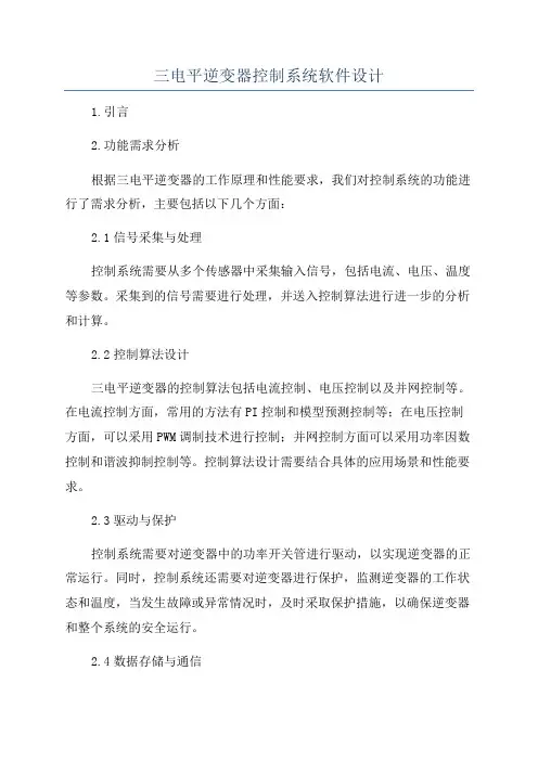
三电平逆变器控制系统软件设计1.引言2.功能需求分析根据三电平逆变器的工作原理和性能要求,我们对控制系统的功能进行了需求分析,主要包括以下几个方面:2.1信号采集与处理控制系统需要从多个传感器中采集输入信号,包括电流、电压、温度等参数。
采集到的信号需要进行处理,并送入控制算法进行进一步的分析和计算。
2.2控制算法设计三电平逆变器的控制算法包括电流控制、电压控制以及并网控制等。
在电流控制方面,常用的方法有PI控制和模型预测控制等;在电压控制方面,可以采用PWM调制技术进行控制;并网控制方面可以采用功率因数控制和谐波抑制控制等。
控制算法设计需要结合具体的应用场景和性能要求。
2.3驱动与保护控制系统需要对逆变器中的功率开关管进行驱动,以实现逆变器的正常运行。
同时,控制系统还需要对逆变器进行保护,监测逆变器的工作状态和温度,当发生故障或异常情况时,及时采取保护措施,以确保逆变器和整个系统的安全运行。
2.4数据存储与通信控制系统需要将采集到的信号和计算结果进行存储,以备后续的分析和故障诊断。
同时,控制系统还需要支持远程通信功能,以方便对逆变器进行远程监控和调试。
3.总体架构设计控制系统由三个主要部分组成:信号采集与处理模块、控制算法模块和驱动与保护模块。
其中,信号采集与处理模块负责从传感器中采集输入信号,并进行预处理;控制算法模块负责根据输入信号进行控制算法的计算和控制决策;驱动与保护模块负责对逆变器进行驱动和保护。
同时,控制系统还需要具备数据存储和通信功能,以支持数据的存储和远程监控。
数据存储模块负责对采集到的信号和计算结果进行存储;通信模块负责与上位机或其他设备进行通信,实现远程监控和控制。
4.控制算法设计根据三电平逆变器的工作原理和性能要求,我们设计了一套完整的控制算法,包括电流控制、电压控制和并网控制等。
在电流控制方面,我们采用了PI控制算法进行实时控制;在电压控制方面,我们采用了PWM调制技术进行实时控制;在并网控制方面,我们采用了功率因数控制和谐波抑制控制等算法进行实时控制。
A Comprehensive Study of Neutral-Point V oltage Balancing Problem in Three-Level Neutral-Point-Clamped V oltage Source PWMInvertersNikola Celanovic,Student Member,IEEE,and Dushan Boroyevich,Member,IEEEAbstract—This paper explores the fundamental limitations of neutral-point voltage balancing problem for different loading con-ditions of three-level voltage source inverters.A new model in DQ coordinate frame utilizing current switching functions is developed as a means to investigate theoretical limitations and to offer a more intuitive insight into the problem.The low-frequency ripple of the neutral point caused by certain loading conditions is reported and quantified.Index Terms—Neutral-point voltage balancing,space vector modulation,three-level converter.I.I NTRODUCTIONS INCE it’s introduction in1981[1],the three-level neutral-point-clamped(NPC)voltage source inverter(VSI),Fig.1, has been shown to provide significant advantages over the con-ventional two-level VSI for high-power applications.The main advantages are as follows.1)V oltage across the switches is only half the dc bus voltage.This feature effectively doubles the power rating of VSI’s for a given power semiconductor device.Moreover,this is achieved without additional,often cumbersome,hard-ware for voltage and current sharing.2)The first group of voltage harmonics is centered aroundtwice the switching frequency[1],[7].This feature en-ables further reduction in size,weight,and cost of passive components while at the same time improving the quality of output waveforms.On the other hand this topology also has its disadvantages.1)Three-level VSI’s require a high number of devices.2)The complexity of the controller is significantly in-creased.3)The balance of the neutral-point has to be assured.The three-level VSI was first considered with respect to high-capacity high-performance ac drive applications[1].To this day, it remains the area where this topology is most widely used [2]–[4],[7]–[9],[15],and[16].Other interesting applications ofManuscript received March10,1999;revised September22,1999.Recom-mended by Associate Editor,F.Z.Peng.The authors are with the Department of Electrical and Computer Engi-neering,Virginia Polytechnic Institute and State University,Blacksburg,V A, 24061-0111USA.Publisher Item Identifier S0885-8993(00)02327-9.Fig.1.Circuit schematic of a three-level VSI.this technology include static V AR compensation systems[11],[12],HVDC transmission systems[18],active filtering applica-tions,as well as applications in power conditioning systems forsuperconductive magnetic energy storage(SMES)[13].The neutral-point(NP)voltage balancing problem ofthree-level NPC VSI’s has been widely recognized in litera-ture.Various strategies have been presented,and successfuloperation has been demonstrated with a dc-link voltage balancemaintained.In addition,some of the proposed algorithms avoidthe narrow pulse problem[5],[9],minimize losses by notswitching the highest current[10],or share the balancing taskwith front-end converters as in[2].NP control for the carrier-based PWM has been studiedin[15]–[17].In[15],the switching frequency optimal PWMmethod is introduced.This method controls the NP by,essen-tially,adding the zero sequence voltage to the inverter output.This work was extended in[16],where the authors propose ananalytical method for analysis of the NP potential variation,show some limitations of the NP control,and also deal with thedc-link capacitors design issues.In[17],the authors analyzethe stability of the NP control based on an insightful dynamicmodel of the NP control they developed.This paper discusses the issues of NP control from the spacevector modulation(SVM)point of view.In addition,the broaderrange of inverter operating conditions is addressed,and a newmathematical formulation of NP balancing problem is given.Furthermore,low-frequency NP voltage ripple,normalized withthe output current and the size of the dc-link capacitors,is givenfor all operating conditions.0885-8993/00$10.00©2000IEEEII.P RINCIPLE OF O PERATIONAll available voltage space vectors for three-level VSI’s are shown in Fig.2.These vectors,called switching-state vectors,represent inverter output line voltages in two-dimensional(,,or),n e g a t i v e ()p o i n t o f t h e d c l i n k .S h o w n i n F i g .2,s w i t c h i n g s t a t e p o n ,f o r e x a m p l e ,i s p r o d u c i n g l i n e v o l t a g eso u t p u t i s c o n n e c t e d t o t h en e u t r a l p o i n t ,w h i c h r e s u l t s i n t h e c u r r e n t d i s t u r b i n g t h e N Pv o l t a g e b a l a n c e .N o t a l l t h e v e c t o r s a f f e c t t h e N P b a l a n c e .T h e o n e s t h a t d o a r e s u m m a r i z e d i n T a b l e I .L a r g e v e c t o r s d o n o t a f f e c t t h e N P b a l -a n c e b e c a u s e t h e y c o n n e c t t h e p h a s e c u r r e n t s t o e i t h e r t h e p o s i -t i v e o r n e g a t i v e d c r a i l ,a n d t h e N P r e m a i n s u n a f f e c t e d .M e d i u m v e c t o r s c o n n e c t o n e o f t h e p h a s e c u r r e n t s t o t h e N P m a k i n g t h e N P p o t e n t i a l d e p e n d e n t i n p a r t o n t h e l o a d i n g c o n d i t i o n s .T h e ya r e t h e m o s t i m p o r t a n t s o u r c e o f t h e N P p o t e n t i a l u nb a l a nc e .S m a l l v e c t o r s c o m e i n p a i r s .E a c h v e c t o r i n a p a i r g e n e r a t e s t h e s a m e l i n e -t o -l i n e v o l t a g e s .A s m a l l v e c t o r t h a t c o n n e c t s a p h a s e c u r r e n t t o N P p o i n t w i t h o u t c h a n g i n g t h e s i g n o f t h e c u r -r e n t w i l l b e r e f e r r ed t o a s a p o s i t i ve s m a l l v e c t o r.T h e o t h e r o n e ,c o n n e c t i n g t h e p h a s e c u r r e n t w i t h t h e n e g a t i v e s i g n ,w i l l b e c a l l e d a n e g a t i v e s m a l l v e c t o r.T h e m a j o r i t y of t h e N P v o l t ag e b a l a n c i n g s ch e m e s u s e di n S V M r e l i e s o n s o m e f o r m o f m a n i p -u l a t i o n o f s m a l l v e c t o r s i n a p a i r ,w h e r e t h e r e l a t i v e d u r a t i o n o f p o s i t i v e a n d n e g a t i v e s m a l l v e c t o r s i n a p a i r i s u s u a l l y a dj u s t e d i n o r d e r t o c o m p e n s a t e f o r t h e e r r o r i n N P.I I I .NE U T R A L P O I N T C U R R E N T M O D U L A T I O N G e n e r a l l y ,t h e t a s k o f t h r e e -l e v e l V S I ’s i s t o s y n t h e s i z e t h ed e s i r e d o u t p u t p h a s e v o l t a g es(1)w h e r e t h e m o d u l a t i o n i n d ex,asshown in Fig.3.The reference vector may be synthesized using the space vector modulation (SVM)of the three switching state vectors that are nearest to the reference vector at every sampling instant.The nearest three vectors are selected by locating the reference vector in one of the four small triangles illustrated in Fig.3.For the outer small triangle shaded in Fig.3,the reference vector is synthesizedas(2)(3)Fig.2.Switching state vectorsof three-level VSI.TABLE IN EUTRAL P OINT C URRENTi FORD IFFERENT S PACE V ECTORSFig.3.Synthesis ofVi ii i irelative duration of the positive()smallvectorswithin.In further text,the relative duration of posi-tive and negative small vectors will be called current modulationindex(()is(7)T h e e x p r e s s i o n s f o r t h e o t h e r o u t e r s m a l l t r i a n g l e (2)–(7)a r e s y m m e t r i c .F r o m (7)i t i s o b v i o u s t h a t t h e N P c u r r e n t c o n s i s t s o f t h e n o n c o n t r o l l a b l e c o m p o n e n t,,b u t a l s o o n t h e l o a d c u r r e n t a n d s m a l l v e c t o rd u t y c y c le .T h e s e a d d i t i o n a l c o n s t r a i n t s s i g n if i c a n t l y l i m i t t h e c o n t r o l a u t h o r i t y o v e r t h e N P c u r r e n t i n t h i s s m a l l t r i a ng l e r e -g i o n .T h e m i d d l e s m a l l t r i a n g l e r e g i o n ,s h o w n i n F i g .4,i s m o r ef a v o r a b l e f o r b a l a n c i ng th e N P v o l t a g e si n c e t w o s m a l l v e c t o r s a r e a v a i l a b l e .T h e r e f e r e n c e v e c t o r i s s y n t h e s i z e d i n t h e r e g i o nas(9)(11)(13)w h e r e a n da r e t h e N P -c u r r e n t m o d u l a t i o n i n d e x e s f o r t h e s m a l l v e c t o rs(16)(18)T h e i n n e r s m a l l t r i a n g l e r e g i o n i s t h e m o s t a d v a n t a g e o u s f o rt h e N P v o l t a g e b a l a n c i n g b e c a u s e o n l y t h e s ma l l v e c t o r s ,t h o s e t h a t a l l o w f u l l c o n t r o l o f t h e N P c u r r e n t (18),a r e u s e d .U n f o r t u -n a t e l y ,i n t h i s r e g i o n t h e d c -l i n k v o l t a g e i s p o o r l y u t i l i z e d ,a n di t i s r e a s o n a b l e t o e x p e c t i n v e r t e r t o o p e r a t e i n t h i s r e g i o n o n l y d u r i n g s t a r t u p a n d /o r t r a n s i e n t s.F i g .4.S y n t h e s i s o fV i n i n n e r s m a l l t r i a n g l e .I V .L OW F REQUENCY R IPPLE IN N EUTRAL P OINT C URRENT Steady-state low-frequency ripple in the NP-current is caused by periodic variation of the components in (7),(13),and (18)over the output voltage line cycle.In a steady state,the voltagereference vector (1)has constantamplitude,,,,and,as shownin Fig.6.Although the duty cycle functions in Fig.6.are continuous,they are the duty cycles of different switching state vectorsin different sectors.One way to represent how different switching state vectors,used in different sectors,affect the NP current,is to introduce current switching functions.Current switching functions define a mapping between the duty cycle of the vectors,and the NP current that those vectors produce.For example,using this representation the NP current produced by medium vectors can be representedas,is the dutycycle of the medium vector pon,andfor,andfor ,the neutral point current contribution from the medium vector isFig.6.Duty cycles of SVM for modulation index m =0:8.TABLE IIC URRENT S WITCHING F UNCTION FOR M EDIUM VECTORSBy extending this reasoning to small vectors and allsix sectors a set of current switching functions can be defined for small vectors as well.Small vectors’switching functions are shown in Tables III and IV .Finally,all these pieces can be com-bined into a single expression valid for the NP current over the entire linecycleS MALL VECTORSTABLE IVC URRENT S WITCHING F UNCTION FOR SFig.7.Weighing factors for medium vectors for m=0:8.active and reactive components of the load current,respectively. By substituting(21)into(20),the NP current can be expressedas,and so on.Note that(22)is essentially the composite expression com-bining(7),(13),and(18)into one matrix equation valid overthe full line cycle of the output voltage.The NP current in thisformulation still consists of noncontrollable current producedby the application of the medium vector,and the controllablecurrent produced by the small vectors.NP current,resulting from application of medium vectors,can be found by multiplying the direct current by the directweighingfactor.It is apparentthat quadrature component of the current will be weighed muchmore heavily,and will produce much larger low-frequency(LF)ripple than the direct component current.Similarly,NP current resulting from application of small vec-tors depends on“controllable”direct and quadrature weighingfactors multiplying the direct,,and quadrature,,load cur-rent.These factors are given in Fig.8for.These four weighing factors depend not only on small vec-tors duty cycles and the current switching functions that are de-termined by particular type of SVM used,but also on the con-trolinputsand as defined earlier.Two distinct sets ofweighing factors are given in Fig.8.One set of weighing factorswhen only positive small vectors are used(i.e.,)is indicated by a dashed line.Between these two extremecases the weighing factors can be controlled by adjusting cur-rent modulation indexes.The weighing factors for medium vectors are periodic func-tions with zero average value over a line cycle.This means thatin the ideal steady-state case,and currents are constant andthe NP current from medium vectors naturally balances over aline cycle.Finding the size of the LF ripple under these con-ditions will be used to help determine the size of the dc-linkcapacitor for a given NP voltage ripple.Note that the ratio of active and reactive weighing factors isopposite for medium and small rge means largecontrol authority over the NP current through the manipula-tion of current modulation indexes of small vectors,and smallmeans small disturbance from middle vectors.On the otherhand,large means large disturbance from middle vectors,andsmall means small control authority over NP from small vec-tors.This confirms the fact that it is much easier to suppress theLF ripple in the NP when the load has a high power factor.V.NP B ALANCE C ONTROLThere seems to be equivalence in the NP balance controlmechanism between carrier-based,and SVM-based PWMschemes.For carrier-based PWM modulation,all the controlschemes appear to be based on the same concept:they all usesome form of manipulation of output zero sequence voltage.Similarly,all the NP control schemes for SVM-based PWMschemes appear to use some form of manipulation of theredundant small vectors.Note that the difference between thephase voltages of two small vectors in a pair is,in fact,the zerosequence voltage.This seems to be another proof of the dualityof the two PWM methods.Regarding NP balancing control for SVM,and with the re-striction to NTV,three distinctive approaches to the control ofNP might be as follows.1)Passive“control,”where the positive and negative smallvector is selected alternatively in each new switchingFig.8.Weighing factors for small vectors for m=0:8.cycle.This method can work only in the case of perfectly balanced load and perfectly balanced PWM scheme, which is unlikely to happen in practice.This method would have difficulties to recover from line or load transients[15].Still,this“control”method can be used to establish a benchmark for NP controller performance.This benchmark can then be used to evaluate the perfor-mance of other NP control methods.2)Hysteresis type control is perhaps the simplest and mostpopular closed loop NP control scheme.This method requires the knowledge of the current direction in each phase.Based on that information,the small vectors that will move the NP voltage in the direction opposite from the direction of unbalance can be selected.The downside of this method is the current ripple at half the switching frequency.3)Active control schemes that control the current modula-tion indexes m and mFig.10.Normalized amplitude of the LF chargeripple.Fig.11.Capacitor sizes for specified NP ripple with and without NP control.From the analysis in the previous section,it should be ob-vious that,regardless of control scheme,the control authority over the NP current is limited,and the region where exact bal-ancing can be achieved in each switching cycle must exist.This region is given as a shaded area in Fig.9.Note that the graph is symmetrical,and that the unity power factor load represents the most favorable case.For that case,the NP voltage can be bal-anced in every switching cycle for a modulation index as highas,and load powerfactor(23)This should provide sufficient guidelines to size the dc link capacitors for any expected operation mode and desired neutral point voltage ripple value.Consider an example with 1800V dc-link voltageandA,peak phase current,and allow 1%voltage ripple(,the comparison of capacitor sizes for the feedback NP control and the case with passive NP control is summarized in Fig.11.The greatest savings in the size of capacitor can be achieved when the inverter is predominantly supplying active power,while for the operation with purely reactive power the benefits of feedback NP control diminish.VI.C ONCLUSIONIn this paper,NP balancing was investigated for all possible operating conditions of a three-level VSI.A new and general model in the DQ coordinate frame was introduced as a way to investigate the theoretical and practical limitations of NP bal-ancing problem regardless of the type of SVM used.Addition-ally,the low-frequency ripple of the neutral point voltage caused by all possible loading conditions was reported and quantified.Results presented in this study should clarify the tradeoffs be-tween the size of the dc-link capacitor,size of the NP voltage ripple,and the NP balancing method.Based on the investigations reported in this paper and the re-sults reported by other researchers,it can be concluded that the NP balancing problem in three-level NPC VSI topology does not limit the usefulness of this topology for practical applica-tions.This problem can be solved in a satisfactory way using various techniques,depending on the particular system,and its operating point constraints.R EFERENCES[1] A.Nabae,I.Takahashi,and H.Akagi,“A new neutral-point clampedPWM inverter,”IEEE Trans.Ind.Applicat.,vol.IA-17,no.5,pp.518–523,Sept./Oct.1981.[2]M.C.Klabunde,Y.Zhao,and T.A.Lipo,“Current control of a3-levelrectifier/inverter drive system,”IEEE Trans.Power Electron.,vol.11, no.1,pp.57–65,Jan.1996.[3]R.Rojas,T.Ohnishi,and T.Suzuki,“An improved voltage vector controlmethod for neutral-point-clamped inverters,”IEEE Trans.Power Elec-tron.,vol.10,no.6,pp.666–672,Nov.1995.[4]H.L.Liu,N.S.Choi,and G.H.Cho,“DSP based space vector PWMfor three-level inverter with DC-link voltage balancing,”in Proc.IEEE IECON Conf.Rec.,vol.1,1991,pp.197–203.[5]H.L.Liu and G.H.Cho,“Three-level space vector PWM in low indexmodulation region avoiding narrow pulse problem,”IEEE Trans.Power Electron.,vol.9,no.5,pp.481–486,Sept.1994.[6]M.Cosan,H.Mao,D.Boroyevich,and F.C.Lee,“Space vector mod-ulation of three-level voltage source inverter,”in Proc.VPEC Seminar, Sept.1996,pp.123–128.[7]J.Zhang,“High performance control of a three-level IGBT inverter fedAC drive,”in Proc.IEEE Ind.Applicat.Soc.Conf.Rec.,vol.1,1995, pp.22–28.[8]S.Ogasawara and H.Akagi,“A vector control system using a neutral-point-clamped voltage source PWM inverter,”in IEEE Ind.Applicat.Soc.Conf.Rec.,1991,pp.422–427.[9]Y.H.Lee,B.S.Suh,and D.S.Hyun,“A novel PWM scheme for athree-level voltage source inverter with GTO thyristors,”IEEE Trans.Ind.Applicat.,vol.32,no.2,pp.260–268,Mar./Apr.1996.[10] B.Kaku,I.Miyashita,and S.Sone,“Switching loss minimized spacevector PWM method for IGBT three-level inverter,”in IEE Proc.Elec-tric Power Applicat.,vol.144,May1997,pp.182–190.[11]G.C.Cho,G.H.Jung,N.S.Choi,and G.H.Cho,“Analysis and con-troller design of static var compensator using three-level GTO inverter,”IEEE Trans.Power Electron.,vol.11,no.1,pp.57–65,Jan.1996. [12]G.H.Jung,G.C.Cho,S.W.Hong,and G.H.Cho,“DSP based controlof high power static V AR compensator using novel vector product phase locked loop,”in IEEE Annu.Power Electron.Spec.Conf.Rec.,vol.1, 1996,pp.238–243.[13]H.Mao,D.H.Lee,H.Dai,F.C.Lee,and D.Boroyevich,“Evaluationand development of new power electronic technologies for supercon-ductive magnetic energy storage(SMES)using PEBB,”in Proc.VPEC Sem.Proc.,Sept.1997,pp.129–134.[14]V.H.Prasad,S.Dubovsky,N.Celanovic,R.Zhang,and D.Boroyevich,“DSP based implementation of a power electronics control system,”in Proc.VPEC Sem.,Sept.1997,pp.61–67.[15]J.Steinke,“Switching frequency optimal PWM control of a three-levelinverter,”IEEE Trans.Power Electron.,vol.7,July1992.[16]S.Ogasawara and H.Akagi,“Analysis of variation of neutral point po-tential in neutral-point-clamped voltage source PWM inverters,”in Proc.IEEE Ind.Applicat.Soc.Conf.Rec.,1993,pp.965–970.[17] C.Newton and M.Summer,“Neutral point control for multi-level in-verters:Theory,design and operation limitations,”in IEEE Ind.Ap-plicat.Soc.Conf.Rec.,1997,pp.1336–1343.[18]G.Lipphardt,“Using a three-level GTO voltage source inverter in aHVDC transmission system,”in Proc.EPE Conf.Rec.,Sept.1993,pp.151–155.Nikola Celanovic(S’95)received the B.S.degreein electrical engineering from the University ofNovi Sad,Yugoslavia,in1994,the M.S.degree inmechanical engineering from Vanderbilt University,Nashville,TN,in1996,and is currently pursuingthe Ph.D.degree at the Virginia Polytechnic Instituteand State University(Virginia Tech),Blacksburg.He is a Graduate Research Assistant with theCenter for Power Electronics Systems,VirginiaTech.During the summer of1999,he was a summerintern with the General Electric CR&D Center, Schenectady,NY,where he was working on modeling and control of multilevel three-phase drive systems.His research interests include modeling,control design,and applications of high-power,high-frequency power electronicssystems.Dushan Boroyevich(M’99)received the B.S.degreefrom the University of Belgrade,Yugoslavia,in1976,the M.S.degree from the University of Novi Sad,Yu-goslavia,in1982,and the Ph.D.degree from the Vir-ginia Polytechnic Institute and State University(Vir-ginia Tech),Blacksburg,in1986.From1986to1990,he was an Assistant Professorand Director of the Power and Industrial ElectronicsResearch Program,Institute for Power and Elec-tronic Engineering,University of Novi Sad,andlater,Acting Head of the Institute.In1990,he joined the Bradley Department of Electrical and Computer Engineering,Virginia Tech,as an Associate Professor.From1996to1998,he was an Associate Director with the Virginia Power Electronics Center,and since1998,has been the Deputy Director of the NSF Engineering Research Center for Power Electronics Systems,where he is now a Full Professor.His research interests include multiphase power conversion,high-power PWM converters,modeling and control of power converters,applied digital control,and electrical drives. He has published over100technical papers,has three patents,and has been involved in numerous government and industry-sponsored projects in the areas of power and industrial electronics.Dr.Boroyevich is a member of the IEEE Power Electronics Society AdCom, IEEE Industry Applications Society Industrial Power Converter Committees, and Phi Kappa Phi.。
简易光伏并网系统仿真设计光伏并网系统是指将光伏发电系统与市电系统相连接,共同供电的系统。
在设计光伏并网系统时,需要进行系统的规划和仿真,以确保系统的安全稳定运行。
本文将介绍一种简易的光伏并网系统的仿真设计。
首先,需要确定光伏发电系统的规模和组件。
光伏发电系统由光伏组件、直流-交流逆变器和计量仪表等组成。
在仿真设计中,我们可以选择一种常见的组件,如典型的多晶硅太阳能电池板,逆变器选择市面上比较常见的单相逆变器。
其次,需要进行系统电路图的设计。
光伏发电系统的电路图包括光伏组件与逆变器的连接和逆变器与市电网络的连接。
在电路图设计时,需要考虑光伏组件的最大功率点追踪(Maximum Power Point Tracking, MPPT)算法的应用,以确保光伏组件能够在不同日照条件下工作在最佳工作点。
逆变器与市电网络的连接需要考虑保护装置的设置,以确保系统的安全并满足市电网络的要求。
然后,需要进行系统的参数设置。
光伏发电系统的参数设置包括光伏组件的最大功率、发电效率、最大电压和最大电流限制等;逆变器的输入电压范围、输出电压和频率等;市电网络的电压、频率和功率因数等。
这些参数的设置需要参考实际应用的要求和环境条件。
接着,可以利用专业的仿真软件进行系统的仿真分析。
常见的仿真软件有PSCAD、PSIM等。
在进行仿真分析时,可以模拟不同天气条件下光伏发电系统的工作情况,比如晴天、阴天和多云天气,以及不同负荷情况下的系统工作情况。
通过仿真分析可以评估系统的发电能力、对电网的影响以及系统的稳定性。
最后,需要对仿真结果进行数据分析和系统优化。
通过对仿真结果的分析,可以评估系统的性能,并进一步优化系统的设计和参数设置,以提高系统的效率、减少能量损失和提高系统的运行稳定性。
综上所述,简易光伏并网系统的仿真设计包括规划系统的组件和规模、设计系统的电路图、设置系统的参数、进行仿真分析和数据分析优化等步骤。
通过仿真设计,可以提高系统的安全性、稳定性和效益,为实际应用提供参考。
三相三电平光伏并网逆变器的研制的开题报告一、选题背景及意义光伏发电在近年来得到了广泛的推广和应用,逆变器是光伏发电系统中最重要的部件之一,起到将直流电转换成交流电的作用。
为了提高光伏发电系统的效率和安全性,不断优化逆变器的控制策略和电路设计,是当前研究的重点之一。
传统的两级逆变器的输出波形不够平滑,会带来一些问题,如谐波干扰等。
而三相三电平逆变器的输出波形相对平滑,能够减小谐波干扰,提高系统效率。
因此,研究三相三电平光伏并网逆变器的控制策略和电路设计,对提高光伏发电系统的性能有着重要意义和实际价值。
二、主要内容和研究方法本研究拟研制一种三相三电平光伏并网逆变器,并针对该逆变器进行控制策略和电路设计的研究。
主要研究内容包括:1.三相三电平逆变器电路设计。
根据光伏发电系统的要求,设计合适的三相三电平逆变器电路,提高系统效率和稳定性。
2.逆变器控制策略研究。
通过对光伏发电系统的分析和研究,确定逆变器的控制策略,实现逆变器的有效控制和运行。
3.硬件系统实现和测试。
根据电路和控制策略设计的结果,进行硬件系统的实现和测试,验证系统的有效性和可行性。
本研究主要采用实验方法,通过对光伏发电系统的分析和研究,设计出符合要求的三相三电平逆变器电路,并结合控制策略实现控制和运行,最终实现硬件系统,并进行测试,在实验结果的基础上加以优化。
三、预期成果及贡献本研究的预期成果包括:1.设计出一种符合要求的三相三电平光伏并网逆变器电路。
2.研究出逆变器的控制策略,实现逆变器的有效控制和运行,提高系统效率和稳定性。
3.实现硬件系统并进行测试,验证系统的有效性和可行性。
本研究的主要贡献包括:1.提高了光伏发电系统的效率和稳定性,为光伏发电技术的推广和应用提供了技术支持。
2.对三相三电平逆变器的电路设计和控制策略进行了研究和探讨,为该领域的研究提供了新的思路和方法。
3.提供了一种针对光伏发电系统的三相三电平逆变器的控制设计方法,可借鉴其他类似领域研究的方案。
三电平H桥级联型逆变器仿真复现综合设计报告指导老师:*****学生:*****学号:1108******1.级联式逆变器介绍:包括2H桥级联和3H 桥级联,把两个两电平半桥逆变器组成的逆变桥作为功率单元进行级联,叫做2H 桥级联;把两个三电平半桥逆变器组成的逆变桥作为功率单元进行级联,叫做3H 桥级联。
2H 桥级联式虽具有控制方法简单、易扩展等优点,但需要的独立直流电源个数多。
而采用3H 桥级联可以克服钳位二极管或钳位电容多、控制困难和需要独立电源个数多的缺点,是一种很有前途的使用方法。
这种级联式3H 桥多电平逆变器适用于中、高压大功率应用场合。
2.仿真软件的选择:由于此仿真主要是对一种控制方法进行验证的,众所周知,matlab在控制方面具有优势,因此可以运用matlab软件仿真。
但是考虑到此控制方法并不是特别复杂且比较简单,因此也可以用PSIM完成。
3.仿真研究的问题:本仿真主要针对三电平H桥级联式逆变器的拓扑结构和控制方式进行复现。
级联个数的不同,对控制方法也有不同的要求,通过PSIM 软件仿真,验证论文中不同级联个数的不同控制方法的正确性和可行性。
4.仿真结果方面:对三电平H桥功率单元验证控制策略是否正确,逆变输出的电压波形和对谐波的分析是否和论文一致;对奇数个三电平H桥级联验证其三角波载波的初相是否为N N /2*1)(-,输出的逆变电压为14out +=N U 、谐波频次主要分布在6K (k 为自然数)对偶数个三电平H 级联方式验证其功率单元间三角波载波移相是否为N /π,输出谐波频次主要分布2K (k 为自然数)。
5采用PSIM 软件对各个控制方法进行仿真复现5.1三电平H 桥功率单元仿真复现主电路图1 功率单元拓扑主电路控制部分电路图图2 控制部分电路图在控制电路中左桥臂的三角载波初相位为α ,右桥臂的三角载波的初相位为α+180,即左、右桥臂的三相载波的初相位相差180°。
三电平光伏并网逆变器共模电压SVPWM抑制策略研究
发布:2011-09-07 | 作者: | 来源: mahuaxiao | 查看:436次 | 用户关注:
摘要:本文提出了一种优化空间矢量脉宽调制方法来抑制光伏并网逆变器中产生的共模电压。
在分析共模电压产生机理的基础上,对通常SVPWM调制技术进行改进,调整了有效矢量的选择范围,并对开关次序进行优化。
该空间矢量合成算法克服了SPWM调制存在的母线电压利用率低,线性调制区小的问题。
仿真结果表明,该算法可以将共模电压幅值抑制到普通SVPWM算法的1/2,具有良好的有效性和实用性。
1引言目前,多电平变流器以其突出的优点在高压大
摘要:本文提出了一种优化空间矢量脉宽调制方法来抑制光伏并网逆变器中产生的共模电压。
在分析共模电压产生机理的基础上,对通常SVPWM调制技术进行改进, 调整了有效矢量的选择范围, 并对开关次序进行优化。
该空间矢量合成算法克服了SPWM调制存在的母线电压利用率低,线性调制区小的问题。
仿真结果表明,该算法可以将共模电压幅值抑制到普通SVPWM算法的1/2,具有良好的有效性和实用性。
1 引言
目前, 多电平变流器以其突出的优点在高压大功率变流器中得到了日益广泛的应用,它不仅能减少输出波形的谐波,也易于进行模块化设计[1, 2]。
二极管中点箝位式(NPC)三电平拓扑结构即是高压大功率变频器的主流拓扑结构之一[3] 。
然而在三电平变流器的应用中, 也出现了一些问题,特别是共模电压问题。
目前,变频器共模电压的抑制方法主要有两种:一是外加无源滤波器等,或有源滤波器[4-6],这类方法会导致体积和成本显著增加,且不易应用于高压大容量场合;二是通过控制策略从源头减小共模电压,文献[7]、[8]提出一种SPWM消除共模电压的调制方法。
该方式是通过异相调制来消除开关共模电压,但是存在直流电压利用率低、线性调制区过小的问题。
针对SPWM调制的电压利用率低、不利于运用于各种调制比工况下的缺点,本文从三电平逆变器共模电压形成机理出发,提出了一种基于优化电压空间矢量(SVPWM)方法, 可有效抑制三电平逆变器输出共模电压。
并通过
Matlab/Simulink软件对该方法进行了仿真验证, 结果表明效果良好。
2 光伏三电平逆变器及其共模电压
本文研究的三电平光伏逆变器系统如图1所示。
其输入为光伏阵列的直流电压,逆变器主拓扑为NPC三电平结构。
设直流母线电压的幅值为Vdc,用开关状态字“1”,“0”和“-1”分别表示逆变器每相输出为+Vdc/2、0和-Vdc/2的三种状态,则三相三电平逆变器总共有27种不同的开关状态。
根据幅值和相位可以画出三电平逆变器的电压空间矢量图,具体如图2所示。
对于三电平逆变器而言, 必须保证输出电压的基波分量幅值与输出频率成一定的正比关系变化, 其共模电压的计算与它们的触发方式有关。
设Ua、Ub、Uc分别为逆变器的三相相电压。
根据三相三线制的对称性原理, 推得三相输出电压波形的共模电压为:
因而,对应三相三电平每一种开关序列的共模电压大小如表1所示。
表1 输出控制字与共模电压的关系
通常的空间矢量调制策略都会使用图2中所记载的19种有效矢量,以达到直流母线电压利用率高,输出谐波小。
但是会带来较大的输出共模电压,最高VCM幅值会达到了Vdc/3。
图3显示的是母线电压Vdc=600V时,一种普通SVPWM 产生的共模电压最大幅度达到了200V, 这样大的共模电压会对系统造成很大的不利影响。
图3 普通SVPWM下共模电压波形
3 抑制共模电压SVPWM原理
从表1中的27种状态可以看出, 对于可控的PWM输出波来讲, 其输出共模电压的幅值在0Vdc~Vdc/2之间变化。
欲减小共模电压,应尽量不使3个输出端与同一“+”极性端或“-”极性端连接, 避免2个端子一起接到“+”极性端或“-”极性端,而另一个端子接到直流中性点, 如使用表中D类的7个状态字, 此时逆变器的输出共模电压为0,但不能只选用D类矢量,因为那样虽能很好的抑制共模干扰,但却因为少的合成矢量会造成参考电压过渡不平滑,使得逆变器输出线线间电压波形变差,因此需要均衡考虑共模差模问题。
本文所研究的SVPWM 算法中,就是选择合理输出共模电压较小的矢量来合成参考电压矢量。
由表1
可见(111,-1-1-1),(110,101,011, 0-1-1,-10-1,-1-10)八个开关状态造成了很大的共模干扰,因此,本研究就避开这八个开关状态(即图2中方框中的矢量),这样就能从源头上降低逆变器的共模输出电压。
本文具体采用CDE三类矢量,这样,理论上即可以把逆变器输出共模电压幅值降为Vdc/6。
然而可用矢量的减少使得无法采用传统的七段式脉冲触发序列,因此,本策略采用五段式脉冲触发序列。
基于以上分析,可依据下列步骤实现SVPWM算法:
① 确定当前矢量的幅值和角度;
② 判断参考矢量所处的扇区及区域;
③ 确定构成该矢量的实际开关矢量;
④ 确定开关矢量的作用时间及工作顺序。
具体矢量计算方法见文献[3],本文以图4Ⅰ扇区F区为例,在F区中各矢量持续时间为:
式2中:ta,tb,tc分别表示矢量V1、V8、V7在一个PWM周期内的持续时间;;A为输出电压调制比;Ts为开关周期。
开关变换次序为(100,10-1,1-1-1,10-1,100),考虑共模电压抑制后的输出矢量时序如图5所示。
对于该扇区的其它小三角形,按照以上过程,确定矢量作用顺序,计算三角形顶点开关矢量作用时间。
同理,可以计算出其他扇区内各三角形顶点开关矢量作用时间。
4 仿真验证和分析
根据三电平NPC逆变器数学模型和控制策略,验证本文提出的三电平空间矢量调制算法及其共模电压抑制策略的有效性,针对三相电网负载进行了仿真研究,使用的是MATLAB7.0。
以Simulink为平台,SimPower System工具箱为辅助。
考虑到用最短的时间得到结论,模块中的控制算法用基于解释的S文件实现。
三电平五段法在每个采样周期内有一相开关不动作,比三电平七段法减少了每个采样周期内开关次数,从而减小了开关损耗,提高了效率。
由于在一个开关周期内开关次数减少了,逆变输出电压(电流)的THD有所增大,这就对控制器参数和输出滤波器的设计有了更高的要求。
图6为NPC三电平逆变器的总体结构框图,其中Three-level Bridge为NPC 逆变器主拓扑,Three-phase V-I Measurement为主测量模块,SVPWM模块负责产生PWM波。
图6 NPC三电平仿真模型
仿真参数和试验波形如下:电网参数:Em=200V,f=50Hz;滤波电感:LS=1.28mH。
直流母线电压Vdc=600V。
开关频率fS=10kHz,采样频率fN=10kHz。
图7至图10
为仿真试验结果波形图。
对三相输出的相电压和线电压的频谱进行分析,线电压的THD为1.25%,经输出电感滤波后得到正弦波幅值为311.4V, THD下降到0.27%,如图8所示。
相电压的THD为23.96%,主要表现为3次谐波,与普通SVPWM/控制策略下输出相电压(图9)相比较可知,谐波含量还略有下降。
图10为采用优化SVPWM 算法后的共模电压仿真波形。
从图中可以明显看出,该方法可将共模电压完全抑制到直流电压的1/6,为100V。
图10 输出共模电压波形
5 结束语
本文提出了一种简略矢量选择的SVPWM 方法,通过特定的矢量合成算法,将共模电压抑制到其直流母线电压的1/6。
分析和仿真表明, 该方法可以将共模电压幅值抑制到普通SVPWM算法的1/2,即Vdc/6,克服了目前一些SPWM方法的缺陷。
此外, 本方法用软件实现, 无需增加硬件成本, 不仅对其它领域三电平逆变器控制设计有良好参考意义,也具有广阔的应用价值。