石墨烯基超级电容器电极材料28页PPT
- 格式:ppt
- 大小:3.11 MB
- 文档页数:28

Classified Index: TB331U.D.C.: 621.Dissertation for the Master Degree in EngineeringSTUDY ON THE SYNTHESIS AND PROPERTIES OF SUPERCAPACITORS BASED ON 3DSTRUCTURED GRAPHENE ELECTRODESCandidate:Wang XuSupervisor:Prof. Fei WeidongAcademic Degree Applied for:Master of EngineeringSpecialty:Materials Physics and Chemistry Affiliation:School of Materials Science andEngineeringDate of Defence:June, 2015Degree-Conferring-Institution:Harbin Institute of Technology哈尔滨工业大学工学硕士学位论文摘要石墨烯基超级电容器具有大功率密度、高工作效率、长久使用寿命以及轻污染等优势,是取代传统储能系统的理想之选。
但石墨烯本身的性质以及其双电层储能理论极限制约了石墨烯基超级电容器在实际应用中的推广。
本文将针对以上问题,通过引入混合式三维结构、石墨烯表面改性以及与法拉第电容电极材料复合等途径,研究可有效提高石墨烯基超级电容器电化学储能性能的方法。
采用“一步法”通过对Pt/Si基底进行热处理使其表面形成三维多孔结构(Pt nanocup),并采用PECVD法在Pt nanocup表面原位垂直生长石墨烯(VFG),成功制备了三维混合纳米结构石墨烯电极材料(VFG-nanocup)。
该材料通过提高单位面积内石墨烯片的数量,使其比表面积相对于平面基底材料增大了两倍。
同时,石墨烯片的垂直结构可以优化电荷的传输路径,增加电荷传导和储存的有效面积,为电极材料实现高电化学储能性能提供了保证。
___________________________________________________________ 作者简介:陈 宽(1986-),男,江苏人,宁波南车新能源科技有限公司助理工程师,研究方向:电极材料;本文联系人阮殿波(1969-),男,黑龙江人,宁波南车新能源科技有限公司高级工程师,研究方向:超级电容器储能技术;傅冠生(1966-),男,湖南人,宁波南车新能源科技有限公司总经理,研究方向:企业管理; 于智强(1977-),男,浙江人,宁波南车新能源科技有限公司副总经理,研究方向:电容器开发与产超级电容器用石墨烯基电极材料的制备及性能研究阮殿波,陈 宽,傅冠生,于智强 (宁波南车新能源科技有限公司,浙江 宁波 315112)摘要:同传统二次电池相比,超级电容器具有功率密度高、充放电速度快、循环寿命长等优点,是一种新型高效的储能装置,提升其能量密度是目前主要的研究方向。
石墨烯作为一种新型二维碳材料,具有电导率高、比表面积大、化学稳定性强等优异特点,是超级电容器的理想电极材料。
综述了近几年石墨烯基电极材料的制备方法及其性能特点,对于其存在的问题和未来的发展趋势作了简单的阐述。
关键词:石墨烯; 超级电容器; 能量密度; 功率密度; 电极材料 中图分类号:TQ919;TQ127.1Preparation and Property Research of Graphene-based Electrode Materials forSupercapacitorRUAN Dian-bo, CHEN Kuan, FU Guan-sheng, YU Zhi-qiang(Ningbo CSR New Energy Technology Co., LTD, Ningbo Zhejiang 315112,China)Abstract : Compared with traditional secondary battery, supercapacitor has the advantage of high power density, rapid charge/discharge property and long cycle life, it ’s a new efficient energy storage device. At present the main research direction of supercapacitor is improving its energy density. Graphene is a new kind of two dimension carbon material, it has the advantage of high conductivity, high specific surface area and strong chemical stability, it ’s an ideal electrode material of supercapacitor. This review summarized the preparation methods of graphene-based electrode materials and its performance characteristics. Problems and development tend of graphene-based electrode materials are also introduced in this article.Keywords : graphene; supercapacitor; energy density; power density; electrode material1.引言 石墨烯,一种单原子层厚度的二维sp 2杂化碳材料,是碳的其它维数的同素异形体的基本构造单元。
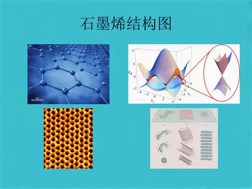

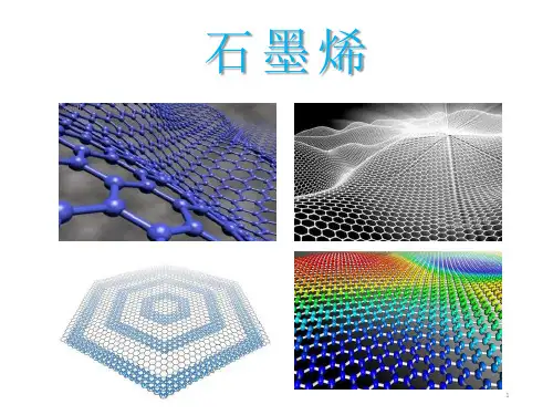
contents •石墨烯概述•石墨烯制备方法•石墨烯表征技术•石墨烯应用领域•石墨烯产业发展现状与趋势•总结与展望目录石墨烯定义与结构定义结构石墨烯的每个碳原子与周围三个碳原子通过共价键连接,形成稳定的六边形结构。
这种结构使得石墨烯具有出色的力学、电学和热学性能。
石墨烯性质与特点力学性质石墨烯是已知强度最高的材料之一,同时还具有很好的韧性,可以弯曲成各种形状而不断裂。
电学性质石墨烯具有优异的导电性能,电子在其中的移动速度极快,使得石墨烯成为理想的电极材料。
热学性质石墨烯具有极高的热导率,可以快速地将热量从一个区域传递到另一个区域,这使得石墨烯在散热领域具有广阔的应用前景。
光学性质石墨烯对光的吸收率很低,且透光性极好,这使得石墨烯在透明导电薄膜等领域具有潜在的应用价值。
石墨烯发现历程及意义发现历程石墨烯最初是由英国曼彻斯特大学的两位科学家通过机械剥离法从石墨中分离出来的。
这一发现引起了科学界的广泛关注,并开启了石墨烯研究的新篇章。
意义石墨烯的发现不仅打破了二维晶体无法稳定存在的传统认知,而且为材料科学、凝聚态物理以及电子器件等领域的发展带来了新的机遇。
石墨烯的优异性能使得它在能源、环保、医疗、航空航天等领域具有广阔的应用前景,有望引领新一轮的技术革命和产业变革。
机械剥离法01020304原理优点缺点应用领域化学气相沉积法在高温下,碳源气体在催化剂表面分解并沉积形成石墨烯。
可控制备大面积、高质量的石墨烯;与现有半导体工艺兼容。
设备成本高,制备过程中可能产生有毒气体。
透明导电薄膜、电子器件、传感器等。
原理优点缺点应用领域原理优点缺点应用领域氧化还原法利用溶剂将石墨剥离成单层或少层石墨烯,适用于大规模生产。
液相剥离法碳化硅外延法电弧放电法激光诱导法通过高温处理碳化硅晶体,使其表面外延生长出石墨烯,适用于制备高质量石墨烯。
利用电弧放电产生的高温高压条件,将石墨转化为石墨烯,但产量较低。
利用激光束照射石墨表面,诱导出石墨烯,但设备成本较高。

**大学研究生课程考试(查)论文2014——2015学年第二学期《石墨烯基超级电容器电极材料研究进展》课程名称:材料化学任课教师:学院:专业:学号:姓名:成绩:石墨烯基超级电容器电极材料研究进展摘要:超级电容器是目前研究较多的新型储能元件,其大的比电容、高的循环稳定性以及快速的充放电过程等优良特性,使其在电能储存及转化方面得到广泛应用。
超级电容器的电极材料是它的技术核心。
石墨烯作为一种新型的纳米材料,具有良好的导电性和较大的比表面积,可作为超级电容器的电极材料。
利用其他导电物质对石墨烯进行改性和复合,可以在保持其本身独特优点的同时提高作为电极材料的导电率、循环稳定性等其他性能。
本文对近年来石墨烯基电极材料在两种不同类型超级电容器中的应用研究进行了综述。
关键词:超级电容器;石墨烯;导电聚合物;金属氧化物随着人类社会赖以生存的环境状况的日益恶化,过多的CO2排放造成气候变化不稳定,人们对能源的开发和研究重点已经转移到绿色能源(如太阳能、风能等)上面[1, 2],但是它们是靠大自然的资源来储能和转化能量的,其发电能力极大程度要受到自然环境以及季节变化的影响,如果被广泛应用于日常生活,有很多不稳定性,这也是目前太阳能、风能领域的瓶颈。
超级电容器,又称作电化学电容器,是一种既稳定又环保的新型储能元件。
它具有充电时间短、使用寿命长、功率密度高、安全系数高、节能环保、低温特性好等优点。
超级电容器在现代科技、工业、航天事业方面的应用都十分广泛,它代表了高储能技术的一次突破。
目前,国内在相关方面做了许多研究,并实现了商业化生产。
但是,它们的广泛应用还存在,例如,能量密低、成本过高等问题。
从原理出发,超级电容器可分为双电层电容器和法拉第赝电容器两类。
两者均是由多孔双电极、电解质、集流体、隔离物4部分所构成(超级电容器结构如图1所示)。
为了减小接触电阻,要求电解质和电极材料紧密接触;隔离物的电子电导要低,离子电导要高,以保证电解质离子顺利穿透。

05025樊泽文等:用于超级电容器的高性能石墨烯/CoMo()复合电极文章编号:1001-9731(2021)05-05025-08用于超级电容器的高性能石墨烯/C0M0O4复合电极*樊泽文,任晶,任瑞鹏,吕永康(太原理工大学煤科学与技术教育部和山西省重点实验室,太原030024)摘要:高性能超级电容器电极材料的开发对于缓解当前的能源危机势在必行,设计和优化混合过渡金属氧化物并研究电化学性能和循环寿命对于超级电容器的实际应用至关重要。
在已开发的混合过渡金属氧化物中,由于电活性材料的导电率差并且与电解质的接触受限制,大大限制了所制备电极的电化学性能。
我们在本文中提出了一种合成石墨烯/CoMoO,纳米片的有利设计,使活性材料均匀生长在三维石墨烯泡沫的网状骨架上,充分提高了活性材料的利用率,其独特的结构也增加了电活性材料与电解质界面之间的接触,使赝电容反应充分发生。
由于石墨烯的高电子传输速率和CoMoO,纳米片的高活性,三维复合电极具有出色的电化学性能,具有相对较高的面积比电容(在1mA cm2下为2737mF cm2)和出色的循环稳定性(在10mA cm2下进行4000次循环后,保留原始比电容的81.76%)这些出色的结果表明,石墨烯/CoMo(O纳米片复合材料具有巨大的潜力,可作为高性能超级电容器的电极材料。
关键词:石墨烯;C o M o()4;纳米片;超级电容器中图分类号:TB332文献标识码:A0引言全球不可再生能源正在迅速消耗,并带来了各种例如极端气候变化等不利情况。
地球上现有的可再生资源,例如太阳能和风能,在使用中存在一个关键缺陷:不能连续使用。
可持续可再生能源的研究和开发已经迫在眉睫,电池和电化学电容器作为现当今的两大能量存储系统已被广泛研究[3]。
与电化学电池和燃料电池相比,基于电化学电容器的储能设备具有更高的功率密度,更快的充放电能力,更长的循环寿命,以及更高的使用寿命[47]。
其中,基于碳基活性材料的双电层电容器的能量密度非常低,因此当前大多数研究集中在贋电容器上。
Graphene-Based UltracapacitorsMeryl D.Stoller,Sungjin Park,Yanwu Zhu,Jinho An,and Rodney S.Ruoff*Department of Mechanical Engineering and Texas Materials Institute,Uni V ersity ofTexas at Austin,One Uni V ersity Station C2200,Austin,Texas,78712-0292Received August22,2008ABSTRACTThe surface area of a single graphene sheet is2630m2/g,substantially higher than values derived from BET surface area measurements of activated carbons used in current electrochemical double layer capacitors.Our group has pioneered a new carbon material that we call chemically modified graphene(CMG).CMG materials are made from1-atom thick sheets of carbon,functionalized as needed,and here we demonstrate in an ultracapacitor cell their performance.Specific capacitances of135and99F/g in aqueous and organic electrolytes,respectively, have been measured.In addition,high electrical conductivity gives these materials consistently good performance over a wide range of voltage scan rates.These encouraging results illustrate the exciting potential for high performance,electrical energy storage devices based on this new class of carbon material.Ultracapacitors based on electrochemical double layer ca-pacitance(EDLC)are electrical energy storage devices that store and release energy by nanoscopic charge separation at the electrochemical interface between an electrode and an electrolyte.1As the energy stored is inversely proportional to the thickness of the double layer,these capacitors have an extremely high energy density compared to conventional dielectric capacitors.They are able to store a large amount of charge which can be delivered at much higher power ratings than rechargeable batteries.An ultracapacitor can be used in a wide range of energy capture and storage applications and are used either by themselves as the primary power source or in combination with batteries or fuel cells. Some advantages of ultracapacitors over more traditional energy storage devices include high power capability,long life,a wide thermal operating range,low weight,flexible packaging,and low maintenance.2Ultracapacitors are ideal for any application having a short load cycle and high reliability requirement,such as energy recapture sources including load cranes,forklifts,and electric vehicles.2,3Other applications that exploit an ultracapacitor’s ability to nearly instantaneously absorb and release power include power leveling for electric utilities and factory power backup.A bank of ultracapacitors,for example,can bridge the short time duration between a power failure and the startup of backup power generators.While the energy density of ultracapacitors is very high compared to conventional dielectric capacitors,it is still significantly lower than batteries or fuel cells.Coupling with batteries(or another power source)is still required for supplying energy for longer periods of time.Thus,there is a strong interest,for example,as enunciated by the U.S.Department of Energy,for increasing the energy density of ultracapacitors to be closer to the energy density of batteries.4In addition to the EDLCs (described above),another class of ultracapacitor that is based on pseudocapacitance can be employed.While the charge storage mechanism of EDLCs is nonfaradic,pseudocapaci-tance is based on faradic,redox reactions using electrode materials such as electrically conducting polymers and metal oxides.The energy densities of pseudocapacitance-based devices can be greater than EDLCs,however,the phase changes within the electrode due to the faradic reaction limits their lifetime and power density.The results reported here are based on EDLC ultracapacitor cells with CMG-based carbon electrode material.An ultracapacitor unit cell is comprised of two porous carbon electrodes that are isolated from electrical contact by a porous separator.5Current collectors of metal foil or carbon impregnated polymers are used to conduct electrical current from each electrode.The separator and the electrodes are impregnated with an electrolyte,which allows ionic current toflow between the electrodes while preventing electronic current from discharging the cell.A packaged ultracapacitor module,depending upon the desired size and voltage,is constructed of multiple repeating unit cells. The CMG system of individual sheets does not depend on the distribution of pores in a solid support to give it its large surface area,rather every chemically modified graphene sheet can“move”physically to adjust to the different types of electrolytes(their sizes,their spatial distribution).Thus, access to the very high surface area of CMG materials by the electrolyte can be maintained while preserving the overall high electrical conductivity for such a network.6,7Because of the relatively high electrical resistance of activated carbon*To whom correspondence should be addressed.E-mail:r.ruoff@ .200810materials,commercial electrodes are limited in thickness and usually contain conductive but low surface area additives such as carbon black to enable rapid electrical charge transfer from the cell.The measured conductivity of these CMG materials (∼2×10²S/m)closely approaches that of pristine graphite.8The high electrical conductivity of the graphene materials eliminates the need for conductive fillers and allows increased electrode thickness.Increasing the electrode thick-ness and eliminating additives leads to an improved electrode material to collector/separator ratio,which in turn further increases the energy density of the packaged ultracapacitor.CMG materials can be synthesized with several methods into various morphologies.9They can be kept suspended in solution,10,11configured into paperlike materials,12,13and incorporated into polymer 6or glass/ceramic 14nanocompos-ites.A form of CMG 8that could be readily incorporated into ultracapacitor test cell electrodes was used for this study.It was synthesized by means of suspending graphene oxide sheets in water and then reducing them using hydrazine hydrate.During reduction,the individual “graphene”sheets agglomerate into particles approximately 15-25µm in diameter,as measured using scanning electron microscope (SEM)images.The C/O and C/N atomic ratios determinedusing elemental analysis by combustion of the CMG powder sample were 11.5and 23.0,respectively.Figure 1a shows a SEM image of the surface of the CMG agglomerate particles.Figure 1b is a transmission electron microscope (TEM)image that shows individual graphene sheets extending from the outer surface.The images illustrate how both sides of the individual sheets at the surface of the agglomerate are exposed to the electrolyte.The surface area of the CMG agglomerate as measured by the N 2absorption Brunauer -Emmett -Teller (BET)method is 705m 2/g.Even though the graphene sheets located within the agglomerated particles may not be accessible by the electrolyte,sheets at the surface can provide an indication of CMG’s potential for use in ultracapacitor electrodes.Electrode material characterization can be performed using either a two or a three-electrode configuration.The two-electrode test cell configuration was used because it provides the most accurate measure of a material’s performance for electrochemical capacitors.15The CMG particles were formed into electrodes using a polytetrafluoroethylene (PTFE)binder,and a stainless steel test fixture was used for electrical testing of the assembled cell.Figure 1c shows two SEM images (low and high magnification)of the surface of an aspreparedFigure 1.(a)SEM image of CMG particle surface,(b)TEM image showing individual graphene sheets extending from CMG particle surface,(c)low and high (inset)magnification SEM images of CMG particle electrode surface,and (d)schematic of test cell assembly.electrode.Figure1d shows a schematic of the two-electrode ultracapacitor test cell andfixture assembly.CMG-based ultracapacitor cells were tested with three different electro-lytes commonly used in commercial EDLCs.1The electro-lytes included an aqueous electrolyte(5.5M KOH)and two organic electrolyte systems,TEA BF4in acetonitrile(AN) solvent and TEA BF4in propylene carbonate(PC)solvent. The performance of the ultracapacitor cells was analyzed using cyclic voltammetry(CV),electrical impedance spec-troscopy(EIS),and galvanostatic charge/discharge.The CV curves and galvanostatic charge/discharge were used to calculate the specific capacitance of the CMG electrodes. The specific capacitance using the CV curves was reported by integrating over the full CV curve to determine the average value.The specific capacitance determined from galvanostatic charge/discharge was calculated from the slope (d V/d t)of the discharge curves.Table1shows the results of specific capacitance(F/g)for the two methods.The EIS data was analyzed using Nyquist plots.Nyquist plots show the frequency response of the CMG electrode/electrolyte system and are a plot of the imaginary component(Z′′)of the impedance against the real component(Z′).Each data point is at a different frequency with the lower left portion of the curve corresponding to the higher frequencies.The cell corresponds more closely to an ideal capacitor the more vertical the curve.The intersection of the curve at the X-axis represents the internal or equivalent series resistance(ESR) of the cell which determines the rate the cell can be charged/ discharged(power capability).The slope of the45°portion of the curve is called the Warburg resistance and is a result of the frequency dependence of ion diffusion/transport in the electrolyte.Although the morphology of the CMG material chosen for thisfirst study is such that only a portion of the graphene sheets(those at the surface of the particles)are exposed to electrolyte,the specific capacitances on the order of100F/g that were measured show the graphene material works well with current commercial electrolytes,has good electrical conductivity,and has very promising charge storage capabil-ity.The cyclic voltammograms(shown in Figure2)that were obtained are nearly rectangular in shape indicating good charge propagation within the electrodes.For activated carbon-based electrodes,the CV curve shape and the specific capacitance can significantly degrade as the voltage scan rate is increased.16Even at scan rates of40mV/sec,the CV curves for the CMG-based electrodes remained rectangular with little variance in specific capacitance.Another indication of good charge propagation is the low variation of specific capacitance for increasing voltage scan rates.Table2shows the specific capacitance of CMG electrodes with KOH electrolyte for scan rates varying from20to400mV/sec.In addition to the low electrical resistance of the CMG material, another possible reason for the insensitivity to varying voltage scan rates is a short and equal diffusion path length of the ions in the electrolyte.This may be due to the electrolyte not penetrating into the particulate thus resulting in only the graphene sheets at the particulate surface being accessed.This could also explain the short Warburg region on the Nyquist plots.Ion diffusion into the interior of the agglomerate would result in greater variations in ion diffusion path lengths and an increased obstruction of ion movement resulting in a much larger Warburg region.The high conductivity of the CMG material also contributes to the low ESR of the cells.The internal cell resistance(real Z′axis from Nyquist plots)was0.15Ω(24kHz),0.64Ω(810kHz), and0.65Ω(500kHz)for KOH,TEABF4/PC,and TEABF4/ AN electrolytes,respectively.The change in specific capacitance with respect to voltage also remains relatively linear at the higher voltages.Test cells with KOH electrolyte were cycled to1V,cells with PC were cycled to2.7V,and AN were cycled to2.5V.The presence of a low percentage of functional groups in the CMG material may contribute to a small amount of pseudocapacitance; however,the relatively linear increase of current with increasing voltage indicates that the charge is primarily nonfaradic in nature.17The specific capacitance of KOH at 40mV/sec scan rate during charging remained almost a constant116F/g between0.1and0.9V.The specific capacitance of the organic electrolyte using AN during discharge at20mV/sec was100F/g in the range from1.5 V to fully discharged at0V.The specific capacitance of the organic electrolyte using PC during discharge at20mV/sec was about95F/g in the range from2.0V to fully discharged at0V.Chemically modified graphenes with good electrical conductivity and very large(and in principle completely accessible)surface areas,are extremely promising candidates for EDLC ultracapacitors.Our results applying these materi-als to ultracapacitors show they are compatible with com-monly used electrolyte systems.In addition,these CMG materials are based on abundantly available and cost-effective graphite.Ultracapacitors based on these materials could have the cost and performance that would dramatically accelerate their adoption in a wide range of energy storage applications. Methods.Graphite oxide(GO)was synthesized from natural graphite(SP-1,Bay Carbon,MI)by a modified Hummers method.17The graphite oxide(100mg)was loaded in a250mL round-bottomflask and purified water(17.4 MΩ,100mL)was then added,yielding an inhomogeneous yellow-brown dispersion.This dispersion was sonicated using a Fisher Scientific FS60ultrasonic bath cleaner(150W)until it became clear with no visible particulate matter.Hydrazine monohydrate(1.00mL,32.1mmol,98%from Sigma Aldrich)was then added,and the suspension was heated in an oil bath at100°C under a water-cooled condenser for 24h over which the reduced graphene oxide sheets gradually precipitated out as a black solid.This product was isolated byfiltration over a medium fritted glass funnel,washed copiously with water(5×100mL)and methanol(5×100Table1.Specific Capacitance(F/g)of CMG Materialgalvanostatic discharge(mA)cyclic voltammogram average(mV/sec)electrolyte10202040 KOH135128100107 TEABF4/PC94918280 TEABF4/AN99959985mL),and dried on the funnel under a continuous air flow through the solid product.The CMG particles consisting of agglomerated graphene sheets were assembled into electrodes by mixing with 3%by weight polytetrafluoroethylene binder (PTFE 60%disper-sion in H 2O,Sigma Aldrich).The mixture was homogenized in an agate mortar,formed into electrodes by rolling the CMG/PTFE mixture into 75µm thick sheets,and finally by punching out 1.6cm diameter discs.The nominal weight of an electrode was 0.0075g.The two electrode test cell assembly is made of two current collectors,two electrodes,and a porous separator (Celgard 3501).The collectormaterialFigure 2.CV (left)and Nyquist (right)plots of CMG material with KOH electrolyte (top),TEA BF 4in propylene carbonate (middle)and TEA BF 4in acetonitrile (bottom).Table 2.Specific Capacitance (F/g)of CMG Material in KOH Electrolyte by Scan Rate (mV/sec)scan rate (mV/sec)CV average specific capacitance (F/g)20101401061001022001013009640097was from Intelicoat Technologies:a4mil conductive vinyl film was used with the aqueous electrolyte and a0.5mil aluminum foil with conducting carbon coating was used with the organic electrolytes.The cell assembly was supported in a testfixture consisting of two stainless steel plates fastened together using threaded bolts.Spacers(PET,Mc-Master Carr)were placed between the SS plates to electri-cally isolate the plates,provide a hermetic seal,and maintain a consistent,even pressure on the cell.Aqueous electrolyte was5.5M KOH(Fisher).Organic electrolytes were prepared using1M tetraethylammonium tetrafluoroborate(TEA BF4,electrochemical grade>99%, Sigma Aldrich)in acetonitrile(anhydrous,99.8%,Sigma Aldrich)or in propylene carbonate(anhydrous,99.7%,Sigma Aldrich).Test cells using organic electrolytes were assembled in a dry nitrogen environment(Atmos glovebag).CV curves,electrical impedance spectroscopy(EIS),and galvanostatic charge/discharge testing was done with an Eco Chemie Autolab PGSTAT100potentiostat equipped with the FRA2frequency response analyzer module and GPES/FRA software.CV curves were scanned at voltage ramp rates of 20and40mV per second.EIS was done using a sinusoidal signal with mean voltage of0V and amplitude of10mV over a frequency range of500000to0.01Hz.Capacitance values were calculated for the CV curves by dividing the current by the voltage scan rate,C)I/(d V/d t).Specific capacitance reported is the capacitance for the carbon material of one electrode(specific capacitance)capacitance of single electrode/weight CMG material of single electrode), as per the normal convention.Galvanostatic charge/discharge was done at constant currents of10and20mA.Capacitance as determined from galvanostatic charge/discharge was measured using C)I/(d V/d t)with d V/d t calculated from the slope of the discharge curves.SEM images were obtained with afield emission gun scanning electron microscope(SUPRA40VP,Zeiss SMT AG,Oberkochen,Germany).TEM images were taken on a JEOL2010F.Elemental analysis was performed by Atlantic Microlab,Inc.,Norcross,Georgia.BET surface area mea-surement was done using a Quantachrome Instruments Nova 2000.Acknowledgment.S.P.was partially supported by a Korea Research Foundation Grant funded by the Korean Govern-ment(MOEHRD)(KRF-2006-352-C00055).This work was otherwise supported by a startup package to RSR by The University of Texas at Austin and by the Texas Nanotech-nology Research Superiority Initiative(TNRSI)/SWAN.This work made use of EIS facilities at the Center for Nano and Molecular Science and Technology,University of Texas at Austin.We thank S.M.Lipka and C.L.Swartz for helpful discussions.R.Istvan and A.L.Ruoff critically read an initial draft of this manuscript.References(1)Conway,B.E.Electrochemical Supercapacitors:Scientific Funda-mentals and Technological Applications;Plenum Publishers:New York,1999.(2)Kotz,R.;Carlen,M.Principles and applications of electrochemicalcapacitors.Electrochim.Acta2000,45,2483–2498.(3)Burke,A.Ultracapacitors:why,how,and where is the technology.J.Power Sources2000,91,37–50.(4)Basic Research Needs for Electrical Energy Storage:Report of theBasic Energy Sciences Workshop on Electrical Energy Storage;April 2-4,2007.Office of Basic Energy Sciences,DOE,July2007. (5)Pandolfo,A.G.;Hollenkamp,A.F.Carbon properties and their rolein supercapacitors.J.Power Sources2006,157,11–27.(6)Stankovich,S.;Dikin,D.A.;Dommett,G.H.B.;Kohlhaas,K.M.;Zimney,E.J.;Stach,E.A.;Piner,R.D.;Nguyen,S.T.;Ruoff,R.S.Graphene-based composite materials.Nature2006,442,282–286.(7)Geim,A.K.;Kim,P.Carbon wonderland.Sci.Am.2008,298,90–97.(8)Stankovich,S.;Dikin, D. A.;Piner,R. D.;Kohlhaas,K. A.;Kleinhammes,A.;Jia,Y.;Wu,Y.;Nguyen,S.T.;Ruoff,R.S.Synthesis of graphene-based nanosheets via chemical reduction of exfoliated graphite oxide.Carbon2007,45,1558–1565.(9)Ruoff,R.Calling all chemists.Nat.Nanotechnol.2008,3,10–11.(10)Stankovich,S.;Piner,R.D.;Chen,X.Q.;Wu,N.Q.;Nguyen,S.T.;Ruoff,R.S.Stable aqueous dispersions of graphitic nanoplatelets via the reduction of exfoliated graphite oxide in the presence of poly(so-dium4-styrenesulfonate).J.Mater.Chem.2006,16,155–158. (11)Li,D.;Muller,M.;Gilje,S.;Kaner,R.;Wallace,G.Processableaqueous dispersions of graphene nanosheets.Nat.Nanotechnol.2008, n/a,n/a.(12)Dikin,D.A.;Stankovich,S.;Zimney,E.J.;Piner,R.D.;Dommett,G.H.B.;Evmenenko,G.;Nguyen,S.T.;Ruoff,R.S.Preparationand characterization of graphene oxide paper.Nature2007,448,457–460.(13)Park,S.;Lee,K.S.;Bozoklu,G.;Cai,W.;Nguyen,S.T.;Ruoff,R.S.Graphene oxide papers modified by divalent ions-Enhancing mechanical properties via chemical cross-linking.ACS Nano2008,2, 572–578.(14)Watcharotone,S.;Dikin,D.A.;Stankovich,S.;Piner,R.;Jung,I.;Dommett,G.H.B.;Evmenenko,G.;Wu,S.E.;Chen,S.F.;Liu,C.P.;Nguyen,S.T.;Ruoff,R.S.Graphene-silica composite thinfilmsas transparent conductors.Nano.Lett.2007,7,1888–1892.(15)Khomenko,V.;Frackowiak,E.;Beguin,F.Determination of thespecific capacitance of conducting polymer/nanotubes composite electrodes using different cell configurations.Electrochim.Acta2005, 50,2499–2506.(16)Lota,G.;Centeno,T.A.;Frackowiak,E.;Stoeckli,F.Improvementof the structural and chemical properties of a commercial activated carbon for its application in electrochemical capacitors.Electrochim.Acta2008,53,2210–2216.(17)Stankovich,S.;Piner,R.D.;Nguyen,S.T.;Ruoff,R.S.Synthesisand exfoliation of isocyanate-treated graphene oxide nanoplatelets.Carbon2006,44,3342–3347.NL802558Y。
石墨烯电极材料
石墨烯是一种由碳原子构成的单层二维晶体材料,具有极高的导电性、导热性、机械强度和化学稳定性等特点。
因此,石墨烯被广泛地研究和应用于电极材料领域。
石墨烯电极材料具有以下特点:
1. 高导电性:石墨烯是一种具有零带隙的半金属材料,电子能量带结构的特殊性质使其具有极高的电导率。
2. 高比表面积:由于石墨烯的单层结构,其比表面积非常大,可达到2630m2/g,这使得石墨烯电极材料具有非常高的电容值。
3. 高化学稳定性:石墨烯具有很强的化学稳定性,能够在各种环境下稳定存在,不易被化学物质腐蚀。
4. 可调性:通过对石墨烯材料进行氧化、还原等处理,可以调节其电学性质,从而实现对电极性能的调控和优化。
由于石墨烯电极材料具有以上优异的性能,因此在超级电容器、锂离子电池、太阳能电池等领域得到了广泛应用,并被认为是未来电极材料的研究热点之一。
- 1 -。