PointGrey产品介绍介绍
- 格式:pdf
- 大小:1.41 MB
- 文档页数:28
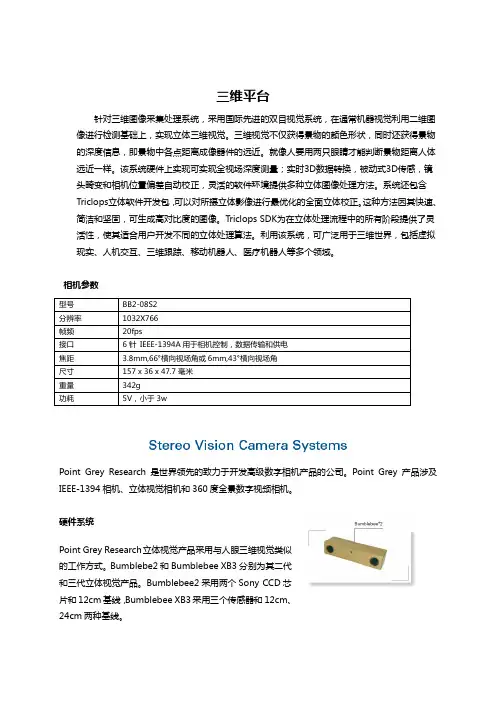
三维平台针对三维图像采集处理系统,采用国际先进的双目视觉系统,在通常机器视觉利用二维图像进行检测基础上,实现立体三维视觉。
三维视觉不仅获得景物的颜色形状,同时还获得景物的深度信息,即景物中各点距离成像器件的远近。
就像人要用两只眼睛才能判断景物距离人体远近一样。
该系统硬件上实现可实现全视场深度测量;实时3D 数据转换,被动式3D 传感,镜头畸变和相机位置偏差自动校正,灵活的软件环境提供多种立体图像处理方法。
系统还包含Triclops 立体软件开发包,可以对所摄立体影像进行最优化的全面立体校正。
这种方法因其快速、简洁和坚固,可生成高对比度的图像。
Triclops SDK 为在立体处理流程中的所有阶段提供了灵活性,使其适合用户开发不同的立体处理算法。
利用该系统,可广泛用于三维世界,包括虚拟现实、人机交互、三维跟踪、移动机器人、医疗机器人等多个领域。
相机参数Point Grey Research 是世界领先的致力于开发高级数字相机产品的公司。
Point Grey 产品涉及IEEE-1394相机、立体视觉相机和360度全景数字视频相机。
硬件系统Point Grey Research 立体视觉产品采用与人眼三维视觉类似的工作方式。
Bumblebe2和Bumblebee XB3分别为其二代和三代立体视觉产品。
Bumblebee2采用两个Sony CCD 芯片和12cm 基线,Bumblebee XB3采用三个传感器和12cm 、24cm 两种基线。
λ 全视场深度测量λ 实时3D 数据转换――每秒产生100万个3D 点λ 与图像和3D 数据完美λ 被动式3D 传感――无需激光或投影仪λ 镜头畸变和相机位置偏差自动校正――无需手动和在线校正λ 高质量CCD 传感器和高速1394接口λ 灵活的软件环境提供多种立体图像处理方法软件系统Point Grey Research 的立体视觉产品除了提供必要的硬件设备外,最大的特点是还提供完备的图像尺度校正和深度校正的立体视觉软件包。
百乐黑武士销售文案百乐(Barron)在美国的市场,是一家饮料品牌。
百乐的产品主要是一款巧克力、纯天然饮品,也有各种功能饮料。
例如:百乐黑武士。
这款产品的中文名叫做“百乐巧克力”。
百乐巧克力是来自美国加州和马里兰州的四个小城镇生产的一种巧克力,味道甜而不腻,并有少量酸味。
百乐黑武士是由美国百乐公司于2014年8月推出的新品。
百乐黑武士与市面上大多数所谓“百乐”巧克力产品不同之处在于:“百乐”巧克力口味为经典黑巧克力口味和苹果口味;“百乐”巧克力产品则是以纯黑巧克力为基底制作而成;“百乐”口味为多种口味任你选择;“百乐”产品外包装盒则为黑中旗舰款红色。
这种款式产品主要是美国百乐公司生产销售的一种巧克力产品。
在美国百乐公司生产销售的“百乐”巧克力是美国最畅销产品之一;美国百乐公司生产销售、以及美国“百乐”牌商标管理协会注册的产品“百乐”巧克力在美国各地均有销售;在美国百乐公司生产销售、以及美国"百乐"牌商标管理协会注册的产品“百乐”巧克力于美国各地均有销售。
***1、百乐黑武士的包装非常时尚,包装非常精美。
打开外包装,能看到黑武士的包装盒上印有百乐的 logo和百乐黑武士标志以及百乐的标志图案。
包装上写着这款饮料是由美国总部位于加利福尼亚州的百乐公司来进行配方研发以及生产的。
在这款饮料产品里面有一颗美国品牌的黑色珍珠。
包装盒内部全部采用食品级 PVC塑料材质制作而成。
因此,其外部包装非常精美,完全符合现在消费者的审美要求。
在包装背面写有“喝一口这个饮料就像品尝一种来自美国加州的独特风味”。
这款产品就是为美国消费者生产的,并且还提供给了100多个国家的消费者食用。
另外,这款饮料的包装上面有“Barron!》Make Me”字样的 logo。
**点这里可以看出来,百乐公司为了方便消费者可以进行更多消费者在不同国家、不同时间购买到不同品牌的产品。
**2、百乐黑武士的口味多达9种,每一种分别有百乐经典黑巧克力和苹果口感的巧克力。
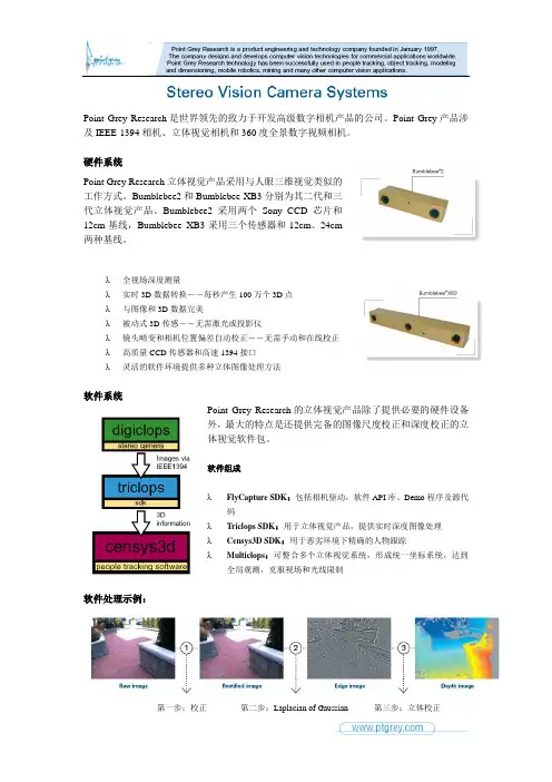
Point Grey Research 是世界领先的致力于开发高级数字相机产品的公司。
Point Grey 产品涉及IEEE-1394相机、立体视觉相机和360度全景数字视频相机。
硬件系统Point Grey Research 立体视觉产品采用与人眼三维视觉类似的工作方式。
Bumblebee2和Bumblebee XB3分别为其二代和三代立体视觉产品。
Bumblebee2采用两个Sony CCD 芯片和12cm 基线,Bumblebee XB3采用三个传感器和12cm 、24cm两种基线。
λ全视场深度测量 λ实时3D 数据转换――每秒产生100万个3D 点 λ与图像和3D 数据完美 λ被动式3D 传感――无需激光或投影仪 λ镜头畸变和相机位置偏差自动校正――无需手动和在线校正 λ高质量CCD 传感器和高速1394接口 λ 灵活的软件环境提供多种立体图像处理方法软件系统Point Grey Research 的立体视觉产品除了提供必要的硬件设备外,最大的特点是还提供完备的图像尺度校正和深度校正的立体视觉软件包。
软件组成λFlyCapture SDK :包括相机驱动,软件API 库、Demo 程序及源代码 λTriclops SDK :用于立体视觉产品,提供实时深度图像处理 λCensys3D SDK :用于恶劣环境下精确的人物跟踪 λ Multiclops :可整合多个立体视觉系统,形成统一坐标系统,达到全局观测,克服视场和光线限制软件处理示例:第一步:校正第二步:Laplacian of Gaussian 第三步:立体校正Bumblebee使用说明一、进入界面使用window中的New Image Window新开窗口,通过左边的窗口,分别可以选择图片RAW格式、Rectified格式、Disparity格式(视差图)。
二、相机参数调节相机的各种参数可通过点击Camera Control按钮,在弹出的窗口中进行shutter、gain等参数调节。

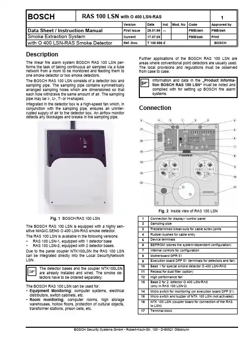
BOSCHRAS 100 LSN with O 400 LSN-RAS1VersionDateInd.Mod. NoCodeApproved byData Sheet / Instruction ManualFirst issue 29.01.99---PMB/dehPMB/deh Smoke Extraction SystemCurrent 17.07.03PMB/zab Print with O 400 LSN-RAS Smoke DetectorRef. Doc. T 138 656 dBOSCH DescriptionThe linear fire alarm system BOSCH RAS 100 LSN per-forms the task of taking continuous air samples via a tubenetwork from a room to be monitored and feeding them to one smoke detector or two smoke detectors.The BOSCH RAS 100 LSN consists of a detector box and sampling pipe. The sampling pipe contains symmetrically arranged sampling holes which are dimensioned so that each hole withdraws the same amount of air. The sampling pipe may be I-, U-, T- or H-shaped.Integrated in the detector box is a high-speed fan which, in conjunction with the sampling pipe, ensures an uninter-rupted supply of air to the detector box. An airflow monitor detects any blockages and breaks in the sampling pipe.Fig. 1 BOSCHRAS 100 LSNThe BOSCH RAS 100 LSN is equipped with a highly sen-sitive MAGIC.SENS O 400 LSN-RAS smoke detector.The RAS 100 LSN is available in the following versions:• RAS 100 LSN-1, equipped with 1 detector base • RAS 100 LSN-2, equipped with 2 detector bases.Due to the panel coupler NTK100LSN the RAS 100 LSN can be integrated directly into the Local SecurityNetwork LSN.The BOSCH RAS 100 LSN can be used for:• Equipment Monitoring: computer systems, electrical distributors, switch cabinets, etc.• Room monitoring: computer rooms, high storage warehouses, hollow floors, protection of cultural objects,transformer stations, prison cells, etc.Further applications of the BOSCH RAS 100 LSN are areas where conventional point detectors are usually used.The local provisions and regulations must be observed from case to case.ConnectionFig. 2 Inside view of RAS 100 LSN1Connection for display-/ control panel 2Sampling pipe3Predetermined break-outs for cable screw joints 4Rubber bushes for cable entry 5Device terminals6EEPROM (stores the system-dependent configuration)7Internal controls for configuration 8Motherboard GPR 519Execution board DFP 51 (terminals for detectors and fan)10Base 1 for special smoke detector O 400 LSN-RAS 11Recess for dust filter (option)12High performance fan13Base 2 for 2. detector O 400 LSN-RAS (only in RAS 100 LSN-2)14Micro switch for monitoring (on execution board DFP 51)15Micro switch and buzzer of NTK 100 LSN (not activated)16NTK 100 LSN (coupler board for connection of the RAS to LSN)17Terminal block2RAS 100 LSNwith O 400 LSN-RASData sheet Copyright by BOSCHDevice connection on GPR 51The electrical connection is via pluggable terminals. Terminal Signal1+ 18 to + 30 VDC20 V3+ 18 to + 30 VDC40 V5+ Supply6Output Fault, St (each events) O-Coll7Output Al 1, O-Coll8Output Al 2, O-Coll9Output St airflow, O-Coll10Fault relay …(a)“Contact (Term. 10 / 12)11Fault relay …(r)“closed in12Fault relay …ra“normal state13Alarm relay 1 …a“14Alarm relay 1 …r“15Alarm relay 1 …ra“16Alarm relay 2 …a“17Alarm relay 2 …r“18Alarm relay 2 …ra“19Input Reset External +20Input Reset External -Terminal assignment for DFP 51The detector bases in the RAS 100 LSN-1 and RAS 100 LSN-2 are wired at the factory according to the following table. Depending on the line technology (loop or tee-off), the corresponding wiring may have to be adapted in the device (see …Product Information BOSCH RAS 100 LSN“, Chapter 7 …Installation“).Te.Connection Wiring1not connected2not connected3bLSN2Detector 1, terminal b1 4Alarm detector 1 Detector 1, terminal c 5not connected6Fan +Fan, red7Fan -Fan, black8Fan tacho Fan, white9not connected10not connected11bLSN2Detector 2, terminal 3 12Alarm detector 2Detector 2, terminal c 13not connectedTerminal assignment for NTK100Te.Connection WiringaLSN2whitebLSN2yellowaLSN1whitebLSN1yellowIII1Ground Central unit, coming III2Ground Central unit, going IV1Power supply +Central unit, redIV2Power supply -Central unit, black VII2Relay fault RAS 100 LSN GPR 51, terminal 10 Terminal assignment for LSN outputs Te.Connection Wiring 1aLSN white 2bLSN yellow Open collector outputsParallel or feedback displays or other consumers can be connected to the open collector (relay).When inductive consumers (e.g. relays) are con-nected, a freewheeling diode must be installed di-rectly next to the consumer. The outputs can be switched to 0 volt and loaded with 100 mA. The outputs are not short-circuit-proof and not potential-free. A con-nection to the outputs affects the total power consumption of the RAS 100 LSN.Fig. 3 Connection of the open collector outputsFor further information and examples, see …Product Infor-mation BOSCH RAS 100 LSN“, Chapter 7, …Installation“.Data sheet Copyright by BOSCHRAS 100 LSNwith O 400 LSN-RAS3Connection drawing for RAS 100LSN-1Connection drawing for RAS 100LSN-2ConfigurationDifferent system-specific configurations can be pro-grammed using the rotary switch, the pushbuttons and the 7-segment indicator on the GPR 51.The configurations are divided into main functions and sub-functions.The selected function is displayed as follows on the 7-segment indicator:•Main functions Number/digit with point •Sub-functions Number/digit without point The key is used for changing from a selected main func-tion to the associated sub-function level and for confirming a changed sub-function.Valid from SW Version 01.02.00ÐMain function (callable by rotary switch position F on motherboard GPR 51)ÐSub-functionMeaning Purpose 4 Device type:0 1 det, foreign brand1 2 det, foreign brand2RAS 100 LSN-1 1 det, BOSCH O 400 LSN-RAS 3RAS 100 LSN-2 2 det, BOSCH O 400 LSN-RAS4 1 det, foreign brand5 2 det, foreign brand 7 Airflow monitoring window:Units:0Window size 0 (small)± 301Window size 1± 402Window size 2± 503Window size 3± 754Window size 4± 1005Window size 5± 1256Window size 6± 1507Window size 7± 2008Window size 8± 4009Window size 9± 600A Window size 10 (large)± 8008 Airflow monitoring On/Off:0Tube break and blockage off1Tube break and blockage on2Tube break off3Blockage off 9 Airflow monitoring delay:0No delay 1Delay 100 sec 2Delay 5 min 3Delay 10 min 4Delay 30 min 5Delay 60 min F Configuration: Display of the set configuration:Main function= static with pointSub-function= flashing without point grey background = Standard configuration IndicationsIndicator and control panelOn the indicator and control panel, four LEDs show theflashes 2x /2x off for 1 min2) No fault triggered (triggers only after expiry of the delaytime Î continuous display).Indications on the motherboard GPR 51 The 7-segment indicator on the GPR 51 may have the fol-lowing indications, depending on the operating state:E briefly = Initialization / HW test–continuous = Unauthorized switch positionflashing = Watchdog indication (= normal mode)In the switch positions …B“ …C“, …E“ and …F“ (+ pressing a key), the following information will be displayed:B Reference value of the airflow (commissioning value).C Actual value of the airflow (actual value).E Error code of any fault present.F Set configuration.The indication of the airflow values (B and C) and the error code (E) happen according to Fig. 4in the form of 4 and 3 numbers in succession.B. /C. / E.100-er10-er1-er EndFig. 4 Display of the airflow values and the error code The configuration currently set is displayed according to Fig. 5. The number sequence appearing on the 7-seg-ment indicator has the following meaning:•Main function Number/digit static with point •Sub-function Number/digit flashing without pointonfigurationisplaymodeevicetype"SD515-1,1detector,anufacturer'sbrand"etectoronitoring"n"larminputs"sdelayed,lf-holding"Smonitoringwindow"indowsize5"Smonitoringelay"sec"ault"elf-holding"ndSmonitoringn/off"ubebreakndblockageon"Fig. 5 Display of the standard configuration (example)Data sheet Copyright by BOSCHRAS 100 LSNwith O 400 LSN-RAS6CommissioningDuring the commissioning of the RAS 100 LSN, an initial reset is required for entering the basic data (e.g. con-nected sampling pipe, motor data). The initial reset also initiates an automatic matching of the airflow monitoring with the connected sampling pipe.Required changes to airflow monitoring should be made after initial reset (system-specific; main function 7 to 9 ) An initial reset causes the configurations always tobe set to the standard configurations associated withthe chosen device type (system-specific configura-tions are discarded).Attention alignment correction (from softwareversion 01.03.00): The RAS 100 LSN performs anautomatic correction of the air flow monitoring 30min,1 h and 18 h after the initial reset. That the ASD will not correct itself on wrong prevailing conditions, there should be done no work with ASD during the alignment conditions like commissioning or function tests.On the control panel, the commissioning sequences are shown as follows:LED …Operation“ (green) = flashes during configuration LEDs …Fault“ + …Operation“ = flash during initial reset LED …Fault“ (yellow) = flashes (2x flashing/2x off) for 1min during alignment correction.StartupBefore the RAS 100 LSN is switched on for the first time, the selection of the device type must be made by means of the rotary switch on the motherboard. The following device types are possible:“2”RAS 100 LSN with 1 detector, O 400 LSN-RAS “3”RAS 100 LSN with 2 detectors, O 400 LSN-RAS When the supply voltage is applied while simultaneously depressing the input key on the GPR 51, the set device type, including the associated configurations, is then automatically loaded (with …2“ and …3“ = standard configu-ration). In addition, the …Initial reset“ procedure is started (0 flashing).Sequence, procedure:a) Device is in the voltage-free state, terminals 1 / 2 dis-connectedb) Select device type with rotary switch (…2“ or …3“)c) Keep button depressed and at the same time switch onASD (connect terminals 1 / 2)d) Do not release button until the number of the selecteddevice type appearse) After the button has been released, 0 begins to flashÎ device type has been loaded, initial reset running. f) After approx. 5 - 6 min the display changes on 1flashing or − static Î the …initial reset“ is finished.g) Switch in position …1“ and press key Î display 1static, after 10s flashing (= normal mode)h) The RAS 100 LSN performs an alignment correctionthree times (30 min, 1h and 18h after the initial reset).Commissioning after extensionsAfter changes of the pipe network due to extensions or reparation an “Initial reset” procedure has to be carried out by the main function “0”. For that choose the rotary switch position “0” and keep the key depressed for approx. 10s during the RAS 100 LSN is in normal operation ( flashing, watchdog). 0 flashing indicates that the initial reset is running.Attention: Device-specific configurations are deleted.The procedure of commissioning sequence is listed below (also see …Product Information BOSCH RAS 100 LSN, Chapter 7.7. …Commissioning“).Use as RAS 100 LSN-1, with standard configuration (Example)Measure DisplayProcessNote(1) Sampling pipe must have been checked for correct installa-tion (connection points, sampling holes). The smoke de-tector or detectors must be inserted and the cover of theÎContinued to (6) or (18)7 RAS 100 LSNwith O 400 LSN-RASData sheetCopyright by BOSCHChange of standard configurationExample of change of airflow monitoring to:…Window size 2, delay 5 min“.MeasureDisplayProcess NoteBefore the standard configuration can be changed, the selectionof the device type and an initial reset must have been performed(18) Attention!! Automatical alignment cor-rection after 30 min, 1h and 18h. Operations from point (18) notcarrying out during alignment correction (LED …Fault“ flashes 2x).Output of the commissioning valuesioning after a timeout of 5 min. = fault)Measurements/ Commissioning protocolThe following measurements must be performed:• Voltage at ter. 1 (+), 2 (-) Î setpoint = 24 to 28 VDC • Airflow value in the switch position …B“ and …C“ (+ keydepressed)• Configuration in the switch position …F“ (+ key de-pressed)The airflow values and the configuration are displayed on the 7-segment indicator according to …Indications on the motherboard“. The results of the measurement should be entered in the attached commissioning protocols.The airflow values of the commissioning (position …B“ and …C“) and the configuration (position …F“) should also be recorded on the attached commissioning sticker. This sticker should then be stuck inside the cover of the elec-tronics chamber.Only the values of the 1st commissioning should be entered on the commissioning sticker (correc-tion after waiting for 1 h). If an initial reset is re-quired after maintenance work on the tube network (cleaning of the sampling holes, replacement of the dust filter), the values …B“ and …C“ should be entered only in the commissioning protocol.The entry on the commissioning sticker may be changed only after:• Initial reset, owing to changes to the sampling pipe(extension/conversion),• Initial reset, owing to replacement of fan or mother-board GPR 51.The protocol is a sort of curriculum vitae of the RAS 100LSN. The commissioning protocol must be filled in consci-entiously and completely and then returned to the elec-tronics chamber. If necessary, a copy may be filed in the systems file.Checking of fault and alarm triggering Triggering of fault and alarm on the RAS 100 LSN after removal of the cover of the detector chamber. Checking for correct alarm transmission (zone/line) to FACP.Block or switch off fire control installation remotealarm to superior FACP.Attention!! Automatical alignment correction after 30 min, 1h and 18h (LED …Fault“ flashes 2x). Following operations not carrying out during the alignment correc-tion.Test event Procedure ActionCover monitoring Open detectorchamber cover• Fault LED flashes• After expiry of the airflowdelay, ASD triggers fault Îfault to FACP ➀Detector moni-toring •After fault re-set of preced-ing test presscover tamperinside detectorchamber im-mediately•Remove de-tector• RAS 100 LSN triggers faultÎ fault to FACP ➀ / ➁• With connection accordingfrom FACP line Î ASDtriggers no fault Î fault di-rectly to FACP ➀ / ➁Test alarm Spray detectorwith test gas • RAS 100 LSN triggers alarm Î Alarm to FACP ➀/ ➁➀The RAS 100 LSN must be reset between the individ-ual controls (preferably at the FACP, as a reset at the RAS 100 LSN does not reset the FACP).➁If two detectors are provided (RAS 100 LSN-2), the control has to be carried out individually for both de-tectors.After completion of the controls, the detector chamber has to be closed again.After the end of all commissioning work, the rotaryswitch position …1“ must be set on the RAS 100LSN (pos. for normal mode). The RAS 100 LSN may be left only in the state of the watchdog display - flashing point of the 7-segment indicator. (Otherwise incomplete commissioning and trigger a fault after a timeout of 5 min = Fault).Article numbers / Spare partsBrief description ID-Nr: Bosch Art. No.SECURITON BOSCH RAS 100 LSN-1 4.998.030.987BOSCH RAS 100 LSN-2 4.998.030.991Smoke det. O 400 LSN-RAS 4.998.115.986Motherboard GPR 51115.215317 Lead-through board DFP 51115.215325 Indication a. Control Board BAP 51115.215333 Fan035.209732 Cable screw union PG 11428.187046 Cable screw union PG 13.5428.205737 Lock nut PG 11428.015245 Lock nut PG 13.5428.162116 Dust filter (option)022.212458 Dust filter box (option)from manufacturer on request Product InformationRAS 100 LSN4.998.121.289 Commissioning protocol T 139 121Dimensioned drawingchamberDetectorchamberConnect. for samplingAir outlet (connectionfor sampling piperecycling, optional) Fig. 3 Detector box BOSCH RAS 100 LSNTechnical DataType RAS 100 LSN Supply voltage range18 to 30 V DC Current consumption max. at:24 V DCNormal / Fault approx. 280 mAAlarm 1 + 2approx. 280 mA Switch-on current peak (caused by FACP protective elements on ASD supply input)for max. 1 ms approx. 5 A Sampling pipe (length, dimensions, holes, etc.)See …Product Information BOSCH RAS 100 LSN, Chapter 3 …Planning“Response range of the O 400 LSN-RAS0,02 ... 0,03 dB/m Protection according to IEC 529 / EN 6052953 IP Ambient conditions according to IEC 721-3-3 / EN 60721-3-3 (1995)Class 3K5 / 3Z1 Extended ambient conditions:Temperature range of detector box0 - +50 °CTemperature range of sampling pipe cAmbient humidity of detector box (briefly without thawing) c≤ 95%Ambient humidity (continuous)≤ 70% Max. load capacity of relay contact50 V DC/ 1 A/ 30 W Pluggable terminals1,5 mm²Cable entry for cableØØ 6 - 9 (- 12 d) mm Housing material ABS-Blend, UL 94-V0 Housing colour grey RAL 2807/ anthracite-violet RAL 3002 Approval (EN 54) VdS ID number G 299 093 Dimensions (W x H x D)285 x 360 x 126 mm Weight2700 gcUse in thawing range only after consultation with the manufacturer.d When cable screw unions PG 13.5 are used.。

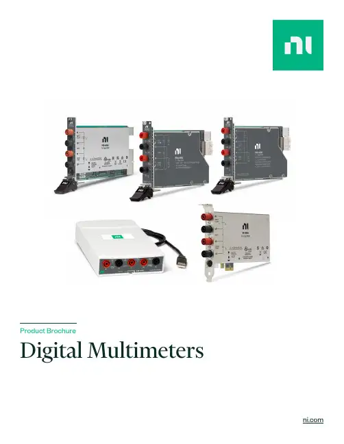
Product BrochureDigital MultimetersContentsPXI Digital Multimeters Digital Multimeter Devices Key FeaturesSoftwareSupporting Documentation Configure a Custom NI System What is PXI?PXI Instrumentation Hardware ServicesPXI Digital MultimetersPXI-4065, PXIe-4080, PXIe-4081, and PXIe-4082Software: Includes interactive soft front panel inInstrumentStudio ᵀᴹ software, API support for LabVIEW and text-based languages, shipping examples, and detailed help filesVoltage measurements up to 1,000 VDC (700 VAC)Current measurements up to 3 AResistance measurements up to 5 G ΩUp to ±500 VDC/VRMS common-mode isolation Up to 1.8 MS/s isolated, 1,000 V waveform acquisitionBuilt for Automated Test and MeasurementPXI Digital Multimeters (DMMs) range from low-cost 6½-digit devices to high-performance 7½-digit models. Some models includespecialized features such as extended measurement ranges, an isolated digitizer mode with sample rates up to 1.8 MS/s, extended calibration cycles, and basic inductance and capacitance measurements. Combined in a single instrument, these features provide a solution to the measurement challenges inherent in traditional precision instruments: limited measurement throughput and flexibility. These DMMs deliver a smarter way to tackle difficult applications in industries ranging from consumer electronics to aerospace and defense.NI’s DMM portfolio is highlighted by the PXIe-4081, the high-performance 7½-digit DMM. It provides 26 bits of resolution and high-stability,metrology-class voltage measurements that range from 10 nV to 1,000 V, current measurements that range from 1 pA to 3 A, and resistance measurements that range from 10 µΩ to 5 G Ω.FIGURE 1PXI-4065, PXIe-4081, and PXIe-4082 Digital MultimetersTable 1. NI offers PXI DMMs ranging from low-cost 6½-digit options to the high-performance 7½-digit DMM.PXI-4065PXIe-4080PXIe-4081PXIe-4082DescriptionBasic6½-Digit DMMHigh-Performance 6½-DigitDMMHigh-Performance 7½-Digit DMMHigh-Performance 6½-Digit DMMMaximum Voltage (V)3003001,000300 Maximum Current (A)3131 Maximum Sample Rate 3 kS/s 1.8 MS/s 1.8 MS/s 1.8 MS/s Basic Accuracy (10 VDC, 2-Year)90 ppm¹25 ppm12 ppm25 ppm Maximum Calibration Cycle1-year2-year2-year2-year DC and AC Voltage●●●●DC and AC Current●●●●2-Wire and 4-Wire Resistance●●●●Frequency/Period-●●●Basic Inductance/Capacitance---●¹One-year calibration specifications are shown for the PXI-4065 because it does not include a two-year calibration option.Detailed View Of PXIe-4081 7½ Digit DMMTiming and synchronization Industry-standard connectivityData streaming through PCIExpressPXI ejector handle FIGURE 2The PXIe-4081 has the functionality of a box DMM with all the feature benefits of PXI.Digital Multimeter DevicesUSB-4065, PCI-4065, and PCIe-4065Software: Includes interactive soft front panel inInstrumentStudio ᵀᴹ, API support for LabVIEW and text-based languages, shipping examples, and detailed help files Voltage measurements up to 300 V Current measurements up to 3 A2-wire and 4-wire resistance measurements up to 100 M ΩUp to ±300 VDC/VRMS common-mode isolation Up to 1.8 MS/s isolated, 300 V waveform acquisitionBuilt for Automated Test and MeasurementNI’s PC-based DMMs perform AC/DC voltage, AC/DC current, and 2- or 4-wire resistance measurements, as well as diode tests. Some models include specialized features such as extended calibration cycles and an isolated, high-voltage digitizer mode with sample rates up to 1.8 MS/s. Combined in a single instrument, these features provide a solution to the measurement challenges inherent in traditional precision instruments: limited measurement throughput and flexibility. These DMMs deliver a smarter way to tackle difficult applications in industries ranging from consumer electronics to aerospace and defense.FIGURE 3USB-4065 and PCIe-4065 Digital Multimeter DevicesTable 2. NI offers DMMs ranging from low-cost USB-powered devices to high-performance PCI-based devices.USB-4065PCI-4065PCIe-4065Description Basic 6½-Digit DMMMaximum Voltage (V)300Maximum Current (A)3Maximum Sample Rate (kS/s)3Voltage Accuracy (10 VDC, 2-Year)90 + 12 ppm Maximum Calibration Cycle 1-yearDC and AC Voltage ●DC and AC Current●2-Wire and 4-Wire Resistance ●Frequency/Period-Detailed View of USB-4065 6½-Digit DMMCompact size (7.0 in x 4.1 in x 1.3 in)Industry-standard connectivityLightweight (10 oz)Bus-powered for portabilityFIGURE 4The USB-4065 DMM has the functionality of a traditional box DMM in a lightweight form factor with USB connectivity.Key FeaturesHigh-Precision MeasurementsThe analog-to-digital converter (ADC) is the backbone of high-performance PXIe-408x DMMs. A unique combination of off-the-shelf high-speed ADC technology and a custom-designed sigma-delta converter provides the noise, linearity, and speed performance required to achieve high-speed and high-precision measurements.The PXIe-4081 uses stable onboard voltage references to provide steady performance across temperature and time. No other DMM in this price range offers this reference source and its accompanying stability, which is why the PXIe-4081 includes a two-year guaranteed accuracy of 12 ppm to further reduce the cost of test by minimizing downtime for instrument calibration. This beats the one-year accuracyspecifications of most traditional benchtop DMMs, providing you with more accurate measurements with lower cost of ownership and less downtime. The PXIe-4081 also uses advanced DMM measurement techniques such as offset compensated ohms, high-order DC noiserejection, and self-calibration to ensure accurate measurements.FIGURE 5Over a 12-hour noise and drift test of 0 VDC with each DMM set to 100 mV input range with 10 power line cycle (PLC) aperture time, the PXIe-4081 (blue) outperforms both the leading 6½-digit (light grey) and 7½-digit (dark grey) benchtop DMMs.FIGURE 6The unique combination of off-the-shelf high-speed ADC technology and a custom-designed sigma-delta converter optimizes linearity and noise for up to 7½-digitprecision and stability while offering digitizer sample rates up to 1.8 MS/s.Flexible Measurement Rate with an Isolated DigitizerTraditional DMMs are designed to provide high resolution and precision, with little regard to acquisition speed. The unique architecture of the PXIe-408x DMMs offers a continuously variable reading rate that ranges from 7 S/s to 10 kS/s, so you can choose the sample rate and resolution you need for your application.FIGURE 7PXIe-408x DMMs can acquire 36X faster than traditional benchtop DMMs, which gives you increased insight into your device under test.Traditional DMMs are designed to provide high resolution and precision, with little regard to acquisition speed. The unique architecture of the PXIe-408x DMMs offers a continuously variable reading rate that ranges from 7 S/s to 10 kS/s, so you can choose the sample rate andresolution you need for your application.FIGURE 8Depiction of the Scanning Process from the NI-SWITCH API to the DMMSynchronization and IntegrationNI PXI DMMs use the inherent timing and synchronization capabilities of the PXI platform to communicate with switches and otherinstruments within the PXI chassis. You can use switches with a DMM to expand the instrument’s measurement capability to hundreds or thousands of test points. NI DMMs “handshake” with NI switches by sending and receiving hardware-timed triggers over the PXI backplane and scanning through a list of switch connections stored in memory on board the switch module. This method of scanning removes the software overhead associated with traditional scan lists and can create a deterministic scan list for faster test execution with more repeatable timing.FIGURE 9Calibration TimelineSynchronization and IntegrationNI DMMs offer self-calibration, which is traditionally found in only the highest resolution DMMs. Self-calibration corrects for all DC gain and offset drifts within the DMM using a precision, high-stability internal voltage reference that has an outstanding temperature coefficient and time drift that account for all resistance and current source drifts. Using the self-calibration feature makes NI DMMs highly accurate and stable at any operating temperature—well outside the traditional 18 °C to 28 °C range.This operation takes less than a minute to complete and requires no external calibrator, which minimizes the maintenance burden of deployed systems. PXIe-408x DMMs have a two-year external calibration cycle thanks to the self-calibration precision circuitry thatminimizes the maintenance burden of deployed systems. Visit to learn more about NI’s calibration services.FIGURE 10LabVIEW VI Built with the NI-DMM APISoftwareSynchronization and IntegrationIn addition to the soft front panel in InstrumentStudio, the NI-DMM driver includes a best-in-class API that works with a variety ofdevelopment options such as LabVIEW, C, C#, and others. To ensure long-term interoperability of DMMs, the NI-DMM driver API is the same API used for all past and current NI DMMs. The driver also provides access to help files, documentation, and dozens of ready-to-run shipping examples you can use as a starting point for your application.NI Software-The Right Tool for the JobNI has a variety of software for engineers working on research, validation, and production test applications. Learn about our software that helps engineers perform quick ad-hoc tests, build an automated test system, automate data analysis and reporting, develop test sequences, and more.LabVIEW DIAdem TestStandAcquire data from NI and third-partyhardware and communicate usingindustry protocolsUse configurable, interactive displayelementsTake advantage of available analysisfunctionsGraphical programming environment thatengineers use to develop automatedresearch, validation, and production testsystems.Display data in multiple 2D-axissystemsPerform calculations with a simplepoint-and-click interfaceAutomate your measurement dataanalysis workflow, from import toanalysisData analytics software for measurementdata search, inspection, analysis, andautomated reporting.Call and execute tests in LabVIEW,Python, C/C++, or .NETConduct complex tasks, such asparallel testingCreate customer operator interfacesand robust tools for deployment anddebuggingTest executive software that acceleratessystem development for engineers invalidation and production.G Web FlexLogger™InstrumentStudio™Data transfer APIs for connecting tosystems written in LabVIEW, Python,or C#Pre-built objects for data display anduser inputIncluded hosting on SystemLink™CloudDevelopment software that helpsengineers create web-based userinterfaces wihtout the need for traditionalweb development skills.Interactive visualization tools formonitoring tests with drag-and-dropcharts, graphs, and controlsAbility to set alarms that monitorsingle channels or groups forunexpected behaviorNo-code data acquisition softwareengineers use to build validation andverification test applications.Customizable layouts for monitoringmultiple instruments at onceInteractively debug in tandem withcodeTDMS file export containinginstrument settings, measurements,and raw dataApplication software that simplifies setupand configuration of NI PXI hardwareTable 3. NI Digital Multimeter DocumentationDocument Type ModelGetting Started Guide NI Digital MultimetersSpecifications PXI-4065, PXIe-4080, PXIe-4081, PXIe-4082 USB-4065, PCI-4065, PCIe-4065Supporting DocumentationConfigure a Custom NI SystemNI’s online system advisors help you create a custom system based on your specific requirements. Use the advisor to choose compatible hardware, software, accessories, and services and then save your selections as configurations for easy quoting and purchasing later. Visit /advisor to learn more.What Is PXI?A Platform Approach to Test and MeasurementPowered by software, PXI is a rugged PC-based platform for measurement and automation systems. PXI combines PCI electrical-bus features with the modular, Eurocard packaging of CompactPCI and then adds specialized synchronization buses and key software features. PXI is both a high-performance and low-cost deployment platform for applications such as manufacturing test, military and aerospace, machine monitoring, automotive, and industrial test. Developed in 1997 and launched in 1998, PXI is an open industry standard governed by the PXI Systems Alliance (PXISA), a group of more than 70 companies chartered to promote the PXI standard, ensure interoperability, and maintain the PXI specification.SoftwareComputer Timing and Synchronization PXI ChassisPCI Express Gen 3 throughput up to 24 GB/s sub-nanosecond latency, P2P streaming, integrated triggeringInstrumentationPXI ModulesDC to mmWave, oscilloscope, programmable power supply, switch/MUX, DMM, VSA, VSG, VST, AWG, SMU, DAQTest Management and Code DevelopmentCode sequencing, database reporting, usermanagement, operator interface, parallelexecution, signal processing. LabVIEW,C/C++, .NET, PythonPXI Embedded ControllerWindows and Real-Time OS options, IntelXeon processing, peripheral ports, displayoutput, integrated hard driveIntegrated with the Latest Commercial TechnologyBy leveraging the latest commercial technology for our products, we can continually deliver high performance and high-quality products to our users at a competitive price. The latest PCI Express Gen 3 switches deliver higher data throughput, the latest Intel multicore processors facilitate faster and more efficient parallel (multisite) testing, the latest FPGAs from Xilinx help to push signal processing algorithms to the edge to accelerate measurements, and the latest data converters from TI and ADI continually increase the measurement range and performance of our instrumentation.PXI InstrumentationNI offers more than 600 different PXI modules ranging from DC to mmWave. Because PXI is an open industry standard, nearly 1,500 products are available from more than 70 different instrument vendors. With standard processing and control functions designated to a controller, PXI instruments need to contain only the actual instrumentation circuitry, which provides effective performance in a small footprint. Combined with a chassis and controller, PXI systems feature high-throughput data movement using PCI Express bus interfaces and sub-nanosecond synchronization with integrated timing and triggering.OscilloscopesSample at speeds up to 12.5 GS/s with 5 GHz ofanalog bandwidth, featuring numerous triggeringmodes and deep onboard memoryDigital InstrumentsPerform characterization and production test ofsemiconductor devices with timing sets and perchannel pin parametric measurement unit(PPMU)Frequency CountersPerform counter timer tasks such as eventcounting and encoder position, period, pulse,and frequency measurementsPower Supplies & LoadsSupply programmable DC power, with somemodules including isolated channels, outputdisconnect functionality, and remote senseSwitches (Matrix & MUX)Feature a variety of relay types and row/columnconfigurations to simplify wiring in automatedtest systemsGPIB, Serial, & EthernetIntegrate non-PXI instruments into a PXI systemthrough various instrument control interfacesDigital MultimetersPerform voltage (up to 1000 V), current (up to3A), resistance, inductance, capacitance, andfrequency/period measurements, as well asdiode testsWaveform GeneratorsGenerate standard functions including sine,square, triangle, and ramp as well as user-defined, arbitrary waveformsSource Measure UnitsCombine high-precision source and measurecapability with high channel density,deterministic hardware sequencing, andSourceAdapt transient optimizationFlexRIO Custom Instruments & ProcessingProvide high-performance I/O and powerfulFPGAs for applications that require more thanstandard instruments can offerVector Signal TransceiversCombine a vector signal generator and vectorsignal analyzer with FPGA-based, real-timesignal processing and controlData Acquisition ModulesProvide a mix of analog I/O, digital I/O,counter/timer, and trigger functionality formeasuring electrical or physical phenomenaHardwareStandard Premium DescriptionDuration at Point of Sale1 year;included 3 years;optional3 years;optionalNI enhances warranty coverage with additional service benefits provided with a hardware service program.Maximum Duration with Renewal< 3 years with service program< 3 years < 3 yearsNI maintains the high performance and availability of your hardware for up to three years with a hardware service program.Extended Repair Coverage•••NI restores your device’s functionality and includes firmware updates and factory calibration; < 10 working days ⁴ + standard shipping.System Configuration,Assembly, and Test¹••NI technicians assemble, install software in, and test your system per your custom configuration prior to shipment.Advanced Replacement ²•NI stocks replacement hardware that can be shipped immediately if a repair is needed.System Return Material Authorization (RMA)¹•NI accepts the delivery of fully assembled systems when performing repair services.Technical Support •••NI provides access to support resources for your hardware.Calibration Plan (Optional)Standard Expedited³NI performs the requested level of calibration at thespecified calibration interval for the duration of the service program.1 This option is only available for PXI, CompactRIO, and CompactDAQ systems.2 This option is not available for all products in all countries. Contact your local NI sales engineer to confirm availability.3 Expedited calibration is only available for the Traceable calibration level.4 This applies to non-RF products only. Standard extended repair coverage for RF products is <15 working days + standard shipping.NI Hardware ServicesAll NI hardware includes a one-year warranty for basic repair coverage and calibration in adherence to NI specifications prior to shipment. PXI systems also include basic assembly and a functional test.NI offers additional entitlements to improve uptime and lower maintenance costs with service programs for hardware. Learn more at /services/hardware .PremiumPlus Service ProgramNI can customize the offerings listed above or offer additional entitlements such as on-site calibration, custom sparing, and lifecycle services through a PremiumPlus Service Program . Contact your NI sales representative to learn more.Technical SupportNI hardware service programs and warranty include access to technical support provided by NI support agents during local business hours.Service requests can be managed online. Additionally, take advantage of NI’s award-winning online resources and communities .©2023 National Instruments Corporation. All rights reserved. National Instruments, NI, and are trademarks of National Instruments. Other product and company names listed are trademarks or trade names of their respective。
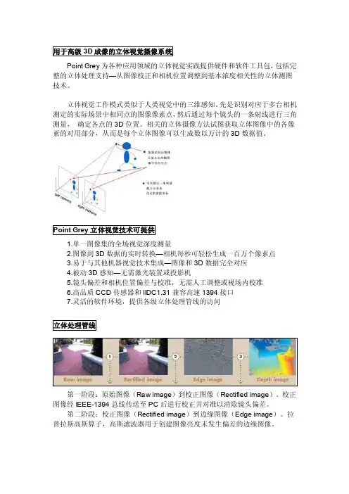
Point Grey为各种应用领域的立体视觉实践提供硬件和软件工具包,包括完整的立体处理支持—从图像校正和相机位置调整到基本浓度相关性的立体测图技术。
立体视觉工作模式类似于人类视觉中的三维感知。
先是识别对应于多台相机测定的实际场景中相同点的图像像素点,然后通过每个镜头的一条射线进行三角测量,确定各点的3D位置。
相关的立体摄像方法试图获取立体图像中的各像素的对用部分,从而是每个立体图像可以生成数以万计的3D数据值。
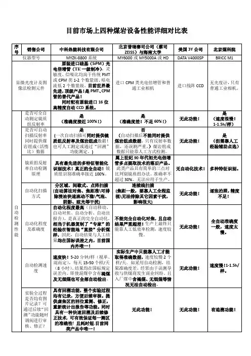
1.单一图像集的全场视觉深度测量2.图像到3D数据的实时转换—相机每秒可轻松生成一百万个像素点3.易于与其他机器视觉技术集成—图像和3D数据完全对应4.被动3D感知—无需激光装置或投影机5.镜头偏差和相机位置偏差与校准,无需人工调整或视场内校准6.高品质CCD传感器和IIDC1.31兼容高速1394接口7.灵活的软件环境,提供各级立体处理管线的访问第一阶段:原始图像(Raw image)到校正图像(Rectified image)。
校正图像经IEEE-1394总线传送至PC后进行校正并对准以消除镜头偏差。
第二阶段:校正图像(Rectified image)到边缘图像(Edge image)。
拉普拉斯高斯算子,高斯滤波器用于创建图像亮度未发生偏差的边缘图像。
第三阶段:边缘图像(Edge image)到深度图像(Depth image)对于深度图像中各像素的相关立体图像,采用绝对差之后的标准通过相关性获得边缘图像中的对应像素。
Point Grey立体视觉摄像系统在出厂时经过了镜头偏差和相机位置偏差的校准,以确保符合所有相机标定的一致性要求,并避免视场内校准的需要。
系统校正过程中,外极线对齐误差在0.1*像素RMS的范围内。
标定结果存储在相机上,是主机软件在即使缺少相机规格的情况下也能够检索图像校正信息。
该项功能保证相机的无缝交互和多相机系统使用的便利性。
专门设计的相机包可保护校准不受机械冲击和振动影响。

更多光源、镜头解决方案————尽在方千科技Contact us :021-6115-2572 6439-7175 | | info@ Vanch Tech offers a wide range of illumination, lens and filter solutions to machine vision…工业相机的相关参数品牌(按字母顺序)型号分辨率像素大小总像素芯片种类芯片大小镜头接口AVT F504B/C 2452x2056 3.45um 500万CCD,Sony ICX6552/3"C Basler PIA24002448x2050 3.45um 500万CCD,Sony ICX6252/3"C Basler A4002352x17267um 400万CMOS 16.5x12mm M42x1/F Dalsa Pantera 4M 2048x20487.4um 400万 15.2x15.2mm M42x1/F Dalsa Pantera 6M 3072x204812um 600万 36.9x24.6mm M72x0.75/F E2VCamelia 4M 2048x204814um 400万 28.7x28.7mm F Funtion(方城)IK5002592x1944 2.2um 500万CMOS 1/2.5"C/CS Hitachi KP-F500SCL 2456x2058 3.45um 500万CCD 2/3"C JAITM/TMC-40002048x20487.4um 400万 2/3"C JAIBM-500GE2456X2058 3.45um 500万CCD 2/3"C Lumenera Aptina 2560x1920 2.2um 500万CCD1/2.5"C Pointgrey FL2G-50S5M/C 2448x2048 3.45um 500万CCD,Sony ICX6552/3"C Princeton(Redlak e)ES40202048x20487.4um 400万CCD,Kodak,KAI-40212/3"C/F SonyXCL-50002448x20503.45um500万CCD2/3"CI.400-600I.400-600万相素相机万相素相机Contact us :021-6115-2572 6439-7175 | | info@ Vanch Tech offers a wide range of illumination, lens and filter solutions to machine 更多光源、镜头解决方案————尽在方千科技2. APO-XNP 2.0/24 400万像素镜头最大可兼容最大可兼容1.31.3英寸英寸C 接口、接口、400400400万像素万像素相机。
P R O D U C T C ATA LO G – I M AG I N G2..End-to-End Imaging SolutionsQuality, Service and SupportWho We ArePoint Grey Research, Inc. is a worldwide leader in the development of advanced digital camera technology prod-ucts for machine vision, industrial imaging, and computer vision applications. Based in Richmond, BC, Canada, Point Grey designs, manufactures and distributes IEEE-1394 (FireWire) and USB 2.0 cameras that are known for their excellent quality, performance, and ease of use.A broad range of hardware, software, and mechanical engineering skills has allowed Point Grey to successfully bring innovative and ground-breaking products to market. This drive for innovation has led to many industry fi rsts, including both the fi rst and the world’s smallest 1394b digital camera.Since its founding in January of 1997, the company’s approach to product pricing, quality control, and customer service has attracted thousands of customers worldwide, and its organic growth through product sales has enabled the company to expand signifi cantly without any outside investment. Point Grey currently employs more than 90 people worldwide, and has a German subsidiary that provides sales and support services to customers in Eu-rope, Africa and Israel. The company has also established a strong network of distributors in Japan, Korea, China, Singapore, and Taiwan.A critical component of any vision system is the speed and reliability of the imaging pipeline, from light hitting the image sensor to data reaching the host system. Point Grey Research has taken ownership of the entire pipeline, and over the last 11 years has created a diverse portfolio of digital cameras, peripheral components, and software. Point Grey offers more than 75 different single-lens, stereo, and 360-degree spherical digital cameras, with a variety of monochrome and color CCD and CMOS image sensors from VGA to 5 megapixels. Many product families also offer board-level or customized options for specifi c OEM applications. In addition, Point Grey has introduced its FirePRO ™ line of professional FireWire hubs, repeaters, and host adapter cards, which are designed to maximize the effectiveness and reliability of the entire imaging pipeline.All Point Grey cameras and FirePRO products are built using state-of-the-art manufacturing facilities, located inthe company’s 41,000 square-foot (3,800 sq m) corporate headquarters. These facilities include a dedicated SMT line, AOI and X-ray machines, industrial clean room, and automated test stations. The “Seal of Quality” label that is applied to each Point Grey camera cannot be printed until the camera has been 100% inspected and tested. This rigorous quality testing, together with hassle-free product warranties, ensures that customers can rely on Point Grey cameras for their demanding vision applications. Point Grey is also proud to offer world-class support on installation, confi guration, customization and troubleshoot-ing, so that all customers derive signifi cant value from their camera systems. Quick response e-mail and phone support, online user manuals and knowledge base articles, and regular software and fi rmware updates are designed to deliver a superior ownership experience.Development accessory kits are also available for every Point Grey camera model. Each kit contains all the hardware needed for rapid design and prototyping, including interface cards, cables, connectors, and makes getting started with Point Grey cameras a quick and easy process.Contact us now for pricing and information on our camera evaluation program!1997199820002002200420052006200720082001Company IncorporationFirst analog stereo vision camera TriclopsFirst IEEE 1394 stereo vision camera DigiclopsFirst sphericalvision camera LadybugFirst IEEE 1394bcamera Dragonfl y ExpressHeadquartersexpansion New products Dragonfl y2Ladybug2Offi ce opens in Germany New productsFlea2Firefl y MVNew productsGrasshopper FirePROHeadquarters expansion First USB 2.0 cameraChameleonNew product Ladybug3First IEEE 1394 imaging cameraFirefl y2009World’s fi rst USB 3.0 Camera42.12216.110200the company’s 41,000 square-foot (3,800 sq m) corporatAOI and X-ray machines, industrial clean room, and autoThe “Seal of Quality” label that is applied to each Point100% inspected and tested. This rigorous quality testing,customers can rely on Point Grey cameras for their demaQuick Reference GuideUNIQUE FEATURESCOMMON FEATURESUNIQUE FEATURES ICON KEY90o Lens Head Option Board Level Option Non-Volatile Data Flash Cable Screw Locking IP67 Rugged HousingIndustry Standard DesignThe mechanical components of every PointGrey camera are designed to maximize usability and minimize size. Every camera is equipped with a C or CS lens mount, ASA/ISO-compliant tripod mounting bracket, status LED, and removable glass/IR fi lter system. All cameras comply with the IIDC v1.31 camera control specifi cation, which allows them to be used with many third-party software packages, such as those from Cognex ®, Matrox ®, MVTec ™, and National Instruments ®.Automatic FeaturesCamera imaging parameters such as exposure, shutter, gain, and brightness can be controlled automatically by the camera, or manually programmed via software. Multiple cameras networked on the same IEEE 1394 bus are automatically synchronized to within 125μs (maximum deviation) of each other, and can synchronize across buses using Point Grey’s MultiSync ™ software.Development Accessory KitThis kit has all the hardware and software required for rapid design and prototyping, including a license of the FlyCapture software development kit (SDK), data cable, interface card, and GPIO wiring harness.Triggering and GPIOThe general purpose input/output (GPIO) connector located on the back of every Point Grey camera is a programmable interface that allows the user to synchronize the camera with external devices such as light sources and GPS units. It can be programmed to accept external trigger signals that initiate the start of expo-sure, output a strobe to a light source, or sendand receive serial data.Updatable FPGAThe field-programmable gate array (FPGA) chipcontrols all camera functionality and can be updated with new functionality in the fi eld.Grasshopper ®Flea ®3Flea ®2Chameleon ®Firefl y ® MV Dragonfl y ®2All 90 lens head and IP67 options available to qualifi ed customers only. Some conditions apply.Frame BufferOn-Board Color Processing Remote Sensor HeadInterfacesC/CS/M12 Lens HolderM 120.3 MP 0.8 MP 1.3 MP 1.4 MP 2.0 MP 5.0 MPMAX RESOLUTION (MP) AND MAX FRAME RATE (FPS)HSHS 200 FPS21 FPS 30 FPS 15 FPS120 FPS 15 FPS 15 FPS 9 FPS30 FPS 30 FPS 80 FPS 15 FPS 15 FPS 7.5 FPS30 FPS30 FPS18 FPS63 FPS 23 FPS60 FPS 30 FPS 20 FPS57.5mm44mm29mm 30mm 29mm29mmHigh sensitivity Sony EXview HAD CCD* Available to qualified customers only. Some conditions apply.High sensitivity Sony EXview HAD CCD * Available to qualified customers only. Some conditions apply.Grasshopper®The high performance Grasshopper IEEE 1394b digital camera line offers eleven monochrome and color CCD models designed to address customer demands for high resolution, fast frame rate, and exceptional sensitivity. The Grasshopper is ideal for applications in machine vision, astronomy and life sci-ences, test and measurement, industrial inspection, and high-speed assembly.Flea ®2The Flea2 line of the world’s smallest IEEE 1394b digital cameras offers a total of twelve monochrome and color CCD models that are designed for versatil-ity. The Flea2 is an ideal solution for industrial imaging and machine vision applications, such as 2D and 3D metrology, electronics and semiconductor inspection, medical visualization, packaging verification, and object recognition.64mm51mmHigh sensitivity Sony EXview HAD CCDDragonfl y®2The fl exible and full-featured Dragonfl y2 IEEE 1394a digital camera line offers achoice of six monochrome and color CCD models. Options include board-level or case-enclosed form factors, and a choice between microlens and C /CS lens mounts. The remote head confi guration is ideal for applications wherethe image sensor must be housed in a very compact space, such as roboticsresearch, object scanning, optical inspection, or head-mounted imaging.30mm29mm29mmFlea®3The fully redesigned, next generation Flea3 camera series builds on the suc-cess of the ultra-compact Flea2 by adding new Sony image sensors to theline-up. The Flea3 also offers a host of new features, including enhanced opto-isolated GPIO; an on-camera frame buffer; non-volatile fl ash memory for userdata storage; new trigger modes; and improved imaging performance.COMING SOON!Continuing product development is vital to Point Grey Research. Point Grey Research reserves the right to alter any published Visit /products/imaging.asp for the latest product information.25.5mm44mm41mmHigh sensitivity Sony EXview HAD CCD*Chameleon®The easy-to-use Chameleon digital camera features a unique combination ofCCD image quality, USB 2.0 interface, and ultra-compact size. The USB 2.0 480 Mb/s interface allows the camera to connect to virtually any computer system without adding an interface card. The Chameleon is an ideal choice for demanding imaging applications such as object and gesture tracking, test and measurement, life sciences, augmented reality, security, biometrics, and robot guidance.Affordably priced at USD $375 per camera (single quantity)Firefl y ®MVCMOS image sensor (0.3 and 1.3 MP), form factor (board-level and housed)and interface (FireWire and USB 2.0) that are designed to address a wide vari-ety of applications in industrial and non-industrial imaging. It is an ideal camera for multitouch, object and gesture tracking, augmented reality, and low-cost machine vision applications.Affordably priced at USD $199 per camera 144mm34mm24.4mm0.3MP model only*M 12M 121394AUSB 2.0• Same C/C++ API for Windows and Linux• Drivers: Microsoft Windows digitally signed drivers• API Library: Complete software library for full camera control • Examples: C/C++, Visual Basic .NET and C# example code • Upgrades: Free unlimited upgrades to the latest versions• Standard Interfaces: ActiveX, TWAIN and DirectShowPROFESSIONAL FIREWIRE COMPONENTSEvery FirePRO IEEE 1394b 800 Mb/s product goes through an intensive testingprocess to ensure compatibility with other FirePRO products and select Point Grey cameras, such as Flea2 or Grasshopper. In addition, FirePRO products are backed by an industry leading 2-year warranty and quick response e-mail and phone support. From large multi-camera arrays to single camera systems, this allows systems integra-tors and developers to quickly build fast and reliable imaging pipelines.FirePRO components maximize system stability through the use of locking screw connections and external power inputs, and minimize downtime due to bus resets or hardware failures. Locking screw connectors / ports not only guarantee a reliable connection through the entire 1394b network, but also reduce stress on internal electronics that can be caused by cable movement. FireWire cables also carry both data and power, minimizing the need for additional cables or external power sources.Secure and PoweredNumber of Ports 223521394b Physical Layer Chip LSI Logic FW643TI TSB81BA3DTI TSB81BA3DTI TSB81BA3DLSI Logic FW643Number of Chips 121131Digital Interface Bilingual 9-pin IEEE 1394b S800 (800 Mb/s) ports with locking screw connectionTransfer Rates 100, 200, 400, 800 Mbit/sVoltage Requirements8-30V , via the IEEE-1394b interface or external power input (if equipped)Power Consumption (max at 12V) 1.5 W 3 W0.5 W1 W1.5 W2.8 WPower Output (max at 12V) 1 A at 12 VExternal Power Input 4-pin IDE connector –Yes Yes Yes Dimensions (W x D x H)Low profi le 92 x 69 mm25 x 56 x 17 mm51 x 67 x 21 mm57 x 94 x 20 mm69 x 57 X 20 mmMass49 g29 g90 g85 g85 gPCI Express CardSingle BusPCI Express CardDual Bus2-Port Repeater 3-Port Hub 5-Port HubLDR 100 m 800 Mb/s Cat5 RepeaterFWB-PCIE-01FWB-PCIE-02FWB-HUB-2PORTFWB-HUB-3PORTFWB-HUB-5PORTFWB-LDR-CAT5Length 4.5 metres10 metres4.5 metresDigital Interface Transfer Rates Voltage (max)Signal Wire Gauge AWG22 and AWG26AWG24AWG28Flex Characteristics ––1,000,000 fl ex cycles, 30mm bend radiusOperating Temperature Storage TemperatureT wo bilingual 9-pin IEEE-1394b S800 (800Mb/s) connectors with locking screw connection100, 200, 400, 800 Mbit/s 8-30V , via the IEEE-1394b interface0° to 45°C -30° to 60°CACC-01-2006ACC-01-2017ACC-01-2012High Flex IEEE 1394bCable10m IEEE 1394b Cable4.5m IEEE 1394b CableThe FlyCapture Software Development Kit (SDK) that comes with every camera provides a common software interface to control all Point Grey FireWire, USB 2.0 and GigE cameras using the same API under Windows or Linux. FlyCapture supports ActiveX, TWAIN and DirectShow interfaces, and includes the FirePRO low-level 1394b interface driver, which enables users to grab images at full 800Mb/s transfer rates. A complete software API library, ready-to-use demo programs, and comprehensive source code examples enable users to easily buildcustom imaging applications.FlyCapture ®2.0P R O D U C T C ATA LO G – I M AG I N GCANADA (Headquarters)Point Grey Research, Inc.12051 Riverside Way Richmond, BC, Canada V6W 1K7T: +1 866.765.0827 (toll free)T: +1 604.242.9937F: +1 604.242.9938E: sales@USAT: +1 866.765.0827 (toll free)E: na-sales@EUROPET: +49 7141 488817-0F: +49 7141 488817-99E: eu-sales@DISTRIBUTORSJAPAN –ViewPLUS Inc. (www.viewplus.co.jp)KOREA –CYLOD Co., Ltd. ()CHINA –LUSTER LightVision ()SINGAPORE –Voltrium Systems (.sg)TAIWAN –Apo Star Co., Ltd. ()Point Grey Research, the Point Grey Research, Inc. Logo, Dragonfl y, Dragonfl y Express, Firefl y, Flea, Grasshopper, Scorpion, Chameleon, FirePRO, and FlyCapture are trademarks or registered trademarks of Point Grey Research, Inc. in Canada and other countries. All other trademarks or registered trademarks are the property of their respective owners. © Point Grey Research, Inc. February 2010. All rights reserved.ASIAE: asia-sales@。
744949.149.24853.2117154Rev Date5.02009/06/055.12009/07/045.22009/07/275.32009/08/025.42009/10/065.52010/03/035.62010/04/085.72010/09/15Tab Pos Code DescriptionUL*Not UL*Boiler No boilerH0111235300BOTTOM GN 1/1X X X X H0121235301GROMMET, CABLE ENTRY X X X X H0141235889DRAIN GRID (with thread)X X X X H0151235305RACK GUIDE SUPPORT (to be used just with rack support with lateral holding system)X X X X H0161235306CONTROL PANEL GASKETX X X X H017123530740 mm FOOT - See also TSB 2008-003 and 006 for more details X X X X H0181235308 COOLING FAN - See also TSB 2009-007 for more detailsX X X X H018.1\COOLING FAN SUPPLY REPARTITION BOARD (See photo catalog available on line for individual codes)X X X X H0191235680LEFT HINGED DOOR DRIP TRAY X X X X H0191235679RIGHT HINGED DOOR DRIP TRAYX X X X H01101235455DOOR HINGE (top position for left hinged door - bottom position for right hinged door)XX X X H01111235681RIGHT HINGED EXTERNAL DOOR ASSEMBLY - (frame and glass) BLUE X X X H01111235686LEFT HINGED EXTERNAL DOOR ASSEMBLY (frame and glass) BLUE X X X H01111235786RIGHT HINGED EXTERNAL DOOR ASSEMBLY (frame and glass) BLACK X X X X H01111235783LEFT HINGED EXTERNAL DOOR ASSEMBLY (frame and glass) BLACKX X X X H01121235314DOOR GASKETX X X X H01131235458DOOR HANDLE MECHANISM X X X X H01141236040CORE PROBE SUPPORT HOLDERX X X X H01151235593DOOR HANDLE BLUE X X X H01151235687DOOR HANDLE BLACKXXXXRevision history tableRevision descriptionNew format with revision sub-level available to improve traceability of modifications.Specified the recommended spare parts with red square around part item number.General revision of codes and descriptions.Introduction of new rack guide support system,new tourniquet with improved internal design,detergent pump non returning valve and the new water level floating device.The new floating device will request to have the boiler with small modifications of pipes positions.In case of floating device replacement need (on old boiler machine)a dedicated retrofit kit (with different design)will be necessary.The new boiler is fully compatible with the old one (that will disapper as a spare),in case of replacement it is necessary to request also the new floating device and its pipes.Inserted a new drain assembly (part 123)and drain grid (part 4)threaded.Created a unique version for exploded views for boiler-boilerless,UL-not UL and digital-analog ovens to improve modifications traceability and managment.Corrected (just on 20levels)part 7code for the oven feet.Inserted reference regarding the cooling fan supply board (part 8.1).Corrected the code for door handle blue and black (part 15),before they were inverted.Inserted on table 3(just on 20 levels) the reference for the second motor supply board (part 58).Part 126 code update - A new dedicated code was created for the part DRAIN BOX INSPECTION COVER for direct machines (so with pipe for boiler closed because not to be used).Part 112.1 code update - the previous code 1235868 was wrong because used for another part. A new dedicated code has been created.Part 131code update.Floating device code was wrongly reported as 1235868while it should be 1235886.1235868is the flosting device kit used to retrofit boiler with old style floating device (now also this code appears on the list).Part 82-a dedicated code in 123xxxx format is now available. Some typing error regarding codes of parts 132n and 133 are now corrected.According to TSB 2009-021 dated 2009/09/04 the cavity fan motor is now with thermal protection for UL and not UL electric ovens.Part 14 "Core probe holder" was created. Technical Service Bulletin (TSB) references added into table.New gasket for the tourniquet external holder has been now inserted (part 107.3).Inserted missing red square around part 94.1.Part 30and 31code and description inversion,before the order was not in accordance with the drawing.Part 131code correction,correct one is 1235868before wrongly written as 1235886.Part 82code and description update,now the reported code HSF...refers to the kit that includes a pair of rack support and the related pan/grid stop rod.Part 82now appears also on table 3for 20levels oven.Part 13code correction,correct one is 1235508before wrongly written as 1235458.Part 69code and description was added.Part 53.2code correction,1235559instead of the wrong 1235599(that is already in use for something else) for version silver-blue and creation of 53.2 code for version silver-black also.H01161235763"L" SHAPED DOOR LIGHT WIRE COVER FOR LEFT HINGED DOOR X X X X H01161235833L SHAPED DOOR LIGHT WIRE COVER FOR RIGHT HINGED DOOR X X X X H01171235764DOOR LIGHT WIRE COVER BLOCK (cavity side)X X X X H01181235576INTERNAL GLASS ASSEMBLY FOR LEFT HINGED DOOR X X X X H01181235577INTERNAL GLASS ASSEMBLY FOR RIGHT HINGED DOOR X X X X H01191235323INTERNAL GLASS HINGE X X X X H01201235765DOOR LIGHT WIRE COVER BLOCK (door side)X X X X H01221235781INTERNAL GLASS SPRING CLIP X X X X H01231235327GLASS RUBBER BUMPER X X X X H01241235461DOOR HINGE (bottom position for left hinged door - top position for right hinged door)X X X X H01251235462SPACER FOR CLOSURE MECHANISM X X X X H01261235468RUBBER STOP FOR METAL SPACER X X X X H01301235467DOOR CATCH (top position for left hinged door - bottom position for right hinged door)X X X X H01311235466DOOR CATCH (bottom position for left hinged door - top position for right hinged door)X X X X H01341235469METAL SPACER X X X X H01351235777CLOSURE MECHANISM COVER FOR LEFT HINGED DOOR X X X X H01351235775CLOSURE MECHANISM COVER FOR RIGHT HINGED DOOR X X X X H01361235893LAMP HOLDER - UL (it can be used both for UL and not UL) X X X X H01371235342LAMP X X X X H01381235596TOP GN 1/1X X X X H01391235344INTERNAL GLASS HINGE PIN X X X X H01401235771LAMP HOLDER SUPPORT FOR LEFT HINGED DOOR X X X X H01401235769LAMP HOLDER SUPPORT FOR RIGHT HINGED DOOR X X X X H01421235703CAVITY DRIP TRAY - See also TSB 2009-004 for more details X X X X H01431235597RIGHT SIDE PANEL X X X X H01441235598LEFT SIDE PANEL X X X X H01451235599BACK PANEL BOTTOM X X X X H01711235123MAGNET - See also TSB 2010-001 for more details X X X X H01721235463DOOR LATCH X X X X H01731235464DOOR LATCH ROD (top position for left hinged door - bottom position for right hinged door)X X X X H01741235465DOOR LATCH ROD (bottom position for left hinged door - top position for right hinged door)X X X X H01751235710LEFT DOOR ASSEMBLY BLUE X X X H01751235706RIGHT DOOR ASSEMBLY BLUE X X X H01751235729LEFT DOOR ASSEMBLY BLACK X X X X H01751235826RIGHT DOOR ASSEMBLY BLACK X X X X H01761235553DOOR LATCH SPRING BRACKET X X X X H01771235554DOOR LATCH SPRING X X X X H01781235555DOOR LATCH SPRING WASHER X X X X H01841235816CLOSURE MECHANISM THICKNESS PLATE X X X X H011481235602OVEN TOP GUTTER X X X X H011491235603 RIGHT TOP SUPPORT X X X X H011501235604LEFT TOP SUPPORT X X X XH011511235605VENT PIPES METAL RING X X X X H011521235606VENT PIPES METAL RING GASKET X X X X H011531235607BACK PANEL TOP X X X H011531235892BACK PANEL TOP (with additional fan space in the center)X X X H011591235713MAGNET HOLDER - See also TSB 2010-001 for more details X X X X H011601235714BRACKET FOR CLOSURE MECHANISM COVER X X X X H011611235715DOOR ROTATION STOP FOR RIGHT HINGED DOOR X X X X H011611235716DOOR ROTATION STOP FOR LEFT HINGED DOOR X X X X H011621235717DOOR HINGE INTERNAL SUPPORT X X X X H024********CONTROL PANEL (metal frame) DIGITAL X X X X H024********CONTROL PANEL (metal frame) ANALOGIC X X X H024********CONTROL PANEL OVERLAY ANALOG BLUE X X X H024********CONTROL PANEL OVERLAY DIGITAL BLUE X X X H024********CONTROL PANEL OVERLAY ANALOG BLACK X X X X H024********CONTROL PANEL OVERLAY DIGITAL BLACK X X X X H024********SINGLE POINT CORE PROBE 4 mm 6 PINS X X X X H0249.11235720MULTIPOINT CORE PROBE 4 mm 6 PINS (OPTIONAL)X X X X H0249.21235722SINGLE POINT CORE PROBE 2 mm 6 PINS (OPTIONAL)X X X X H025********CORE PROBE CONNECTOR 6 PINS X X X X H025********INSTALLATION DIAGRAM FOR CORE PROBE 6 PINS X X X X H025********TRANSFORMER 370+165 VA - UL- NO NEUTRAL X X X H025********TRANSFORMER 370+165 VA - NO NEUTRAL X X X H025********TRASF.ROT.165 VA - WITH NEUTRAL X X X H025********THERMOCOUPLE FOR STATIC RELAY X X X X H025********DISPLAY BOARD DIGITAL X X X X H025********DISPLAY BOARD ANALOGIC X X X H0253.11235018ANALOGIC COMMUTATOR X X X H0253.21235559ANALOGIC COMMUTATOR KNOB (silver-blue)X X X H0253.21235947ANALOGIC COMMUTATOR KNOB (silver-black)X X X H0254\CPU BOARD (See photo catalog available on line for individual codes ) X X X X H0255\POWER SUPPLY BOARD (See photo catalog available on line for individual codes )X X X X H0256\RELAY BOARD (See photo catalog available on line for individual codes )X X X X H025********FUSE10A X X X X H025********MAGNETO THERMIC -UL- WITHOUT NEUTRAL X X X H025********MAGNETO THERMIC NOT UL WITHOUT NEUTRAL X X X H025********MAGNETO THERMIC - WITH NEUTRAL - See also TSB 2009-009 and 022 for more details X X X H02631235124TERMINAL BLOCK BLUE X X X X H02641235125TERMINAL BLOCK GREY X X X X H02651235004MOTOR STATIC RELAY 25A (synchron) X X X X H02661235003STATIC RELAY 125A - For spare parts it is recommended to only carry 125 A which will cover all machine models need X X X X H02681235365CAVITY THERMOCOUPLE X X X X H02691235366BOILER PROBE X X XH027********DOOR SWITCH SENSOR - UL (1.7 m wire) - 20 levels oven with right door may need it with 2.5 meter long wire X X X X H027********DISPLAY BOARD COVER X X X X H027******** ELECTRONIC BOX FRAME SUPPORT X X X X H027********CAVITY HIGH LIMIT THERMOSTAT X X X X H027********ALUMINIUM PLATE X X X X H021*********DETERGENT PUMP TUBE 100 mm lenght X X X X H02112.11235899CONNECTOR DETERGENT PUMP TUBE - DETERGENT TUBE X X X X H02112.21235411DETERGENT TUBE X X X X H02112.31235866WEIGHT & FILTER FOR DETERGENT TUBE X X X X H02113\WIRING (See wiring diagrams available on line for individual codes )X X X X H02114\HYDRAULIC PARTS (See photo catalog available on line for individual codes )X X X X H02115\FLAT CABLE (See photo catalog available on line for individual codes )X X X X H02116\DETERGENT PUMP -UL- 110/120V - (See photo catalog available on line for individual codes )X X X H02116\UL.CABLE FOR -UL DETERGENT PUMP (See photo catalog available on line for individual codes )X X X H02116\DETERGENT PUMP -230V - (See photo catalog available on line for individual codes )X X XH02116.11235874DETERGENT PUMP ADDITIONAL NON RETURNING VALVE 1/4" - 1/4"See also TSB 2009-016 and 2010-002 for more details X X X XH02116.21235878DETERGENT PUMP NON RETURNING VALVE CONNECTOR 8x1/4"See also TSB 2009-016 and 2010-002 for more details X X X XH02117\ WATER SOLENOID VALVE (See photo catalog available on line for individual codes )X X X X H02118\WATER CONNECTION INLET (See photo catalog available on line for individual codes )X X X X H021*********MANOMETER X X X H021*********PRESSURE REGULATOR X X X H021*********PRESSURE REGOLATOR SUPPORT X X X H021*********SPACER FOR DISPLAY BOARD COVER X X X X H02143\BLANK RELAY BOARD FOR OVENS WITHOUT WASHING (See photo catalog available on line for individual codes )X X X X H021*********ELECTRONIC PROTECTING SCREEN X X X X H0357\MOTOR REVERSE BOARD (See photo catalog available on line for individual codes )X X X X H03801235375CAVITY FAN X X X XH03821236031RACK GUIDE KIT (a couple of rack guides with pan/grid stop rods, to be used just with lateral holding system)See also TSB 2008-005 and 2009-015 for more details X X X XH03821236032RACK GUIDE KIT (a couple of rack guides with pan/grid stop rods, to be used just with top-bottom holding system)See also TSB 2008-005 and 2009-015 for more details X X X XH03831235380FAN GUARD X X X X H03851235815FAN GUARD PIN X X X X H03871235523NEBULIZER X X X X H03881235524NEBULIZER WATER PIPE X X X X H0389 + 901235875MOTOR FAN OUTER SCREW + WASHER X X X X H0389.11235876CAVITY FAN INNER MOTOR SCREW X X X X H0391*******HEATER SUPPORT PLATE X X X X H0392*******HEATING ELEMENT 8 KW D.320 208V X X X H0392.11235810HEATING ELEMENT 8 KW D.320 277V/480V X X X H0392.21235805HEATING ELEMENT 8 KW D.320 230V X X X H0392.31235390HEATING ELEMEMT 9KW D.320 230X X X H0394*******FAN MOTOR WITH THERMAL PROTECTION X X X X H0395*******MOTOR COUPLING FLANGE X X X XH0396*******MOTOR COUPLING FLANGE X X X X H03971235396MOTOR SHAFT GASKET X X X X H03991235398MOTOR CAPACITOR X X X X H0311********SAFETY THERMOSTAT PROBE HOLDER X XH0315********CAVITY HEATING ELEMENT PROTECTION COVER X X X X H0310********WASH INJECTOR X X X X H0410********WASH INJECTOR DIAMETER 1,5 mm X X X X H0410********TOURNIQUET ASSEMBLY X X X X H0410********VENT BOX PROBE - (for boiler machines and boilerless machines with humidity control)X X X X H0410********TOURNIQUET EXTERNAL HOLDER - See also TSB 2009-0017 for more details X X X X H04107.11235885CONNECTOR TUORNIQUET EXTERNAL HOLDER - PIPE - See also TSB 2009-0017 for more details X X X X H04107.21235877TUORNIQUET PIPE - See also TSB 2009-0017 for more details X X X X H04107.31235654TOURNIQUET EXTERNAL HOLDER GASKET - See also TSB 2009-0017 for more details X X X X H0411********VENT BOX (with holes for humidity probes)X X X X H0411********VENT BOX (without holes for humidity probes)X X X H0412********RUBBER PIPE X X X X H0412********DRAIN ASSEMBLY (with thread for drain grid insert) X X X X H0412********DRAIN SOLENOID VALVE X X X X H0412********DRAIN BOX INSPECTION COVER (with pipe for boiler drain)X X X H0412********DRAIN BOX INSPECTION COVER (pipe for boiler closed because not to be used)X X XH0412********BOILER - COOKING CHAMBER CONNECTION PIPE X X XH0412********DRAIN ASSEMBLY (with thread for drain grid insert) X X XH0412********BOILER HEATING ELEMENT 7.5 kW 208 V X XH0412********BOILER HEATING ELEMENT 7.5 kW 277 V X XH0412********BOILER HEATING ELEMENT 7.5 kW 230 V X XH0413********BOILER HEATING ELEMENT GASKET X X XH0413********BOILER WATER LEVEL FLOATING DEVICE - 80 mm body length versionSee also TSB 2009-011 and 012 for more details X X XH0413********BOILER WATER LEVEL FLOATING DEVICE KIT - to retrofit new floating (65 mm leght body version) on existing boiler with former designSee also TSB 2009-011 and 012 for more details X X XH0413********WATER SUPPLY PIPE DIAMETER 10 mm - BOILER X X XH0413********WATER SUPPLY PIPE DIAMETER 7.9 mm - BOILER X X XH0413********BOILER WATER LEVEL SUPPORT X X XH0413********BOILER INSULATIONH0413********VENT BOX COUPLING FLANGE X X X X H0413********BLANK BOILER HOLE COVER X X XH0414********VENT BOX PLUG X X X X Red squared numbers correspond to recommended spare parts* UL is a mandatory certification for oven to be sold in USA. UL oven can have different elements voltage, a 110V detergent pump, different transformer, 60 Hz compatible components and few others details.If different, the component is specified in the list as alternative for UL.。
Point Grey 采集软件FlyCapture2使用说明书Point Grey 采集软件 FlyCapture2使用说明书目录前言 (1)1软件安装 (2)2软件使用 (4)2.1设备选择 (4)2.1.1 1394相机或USB相机 (4)2.1.2 网口相机 (4)2.2图像采集 (5)2.2.1 数据记录功能 (6)2.2.2 参数设置功能 (7)前言FlyCapture SDK是加拿大Point Grey(灰点)公司开发的功能丰富,最稳定的软件套件。
它提供了Point Grey公司所有的GigE、1394、USB相机的采集与开发功能,以及所有千兆网卡、1394采集卡、USB3.0采集卡的驱动。
FlyCapture SDK支持Windows XP 32/64及其以上版本和Linux操作系统,支持C、C++、C#、VB等语言对相机的接口函数(API)进行开发工作,简化了面向对象的接口,使应用开发更容易。
1 软件安装Point Grey采集调试软件最新版本为FlyCapture2-2.4,首先要根据系统是32位还是64位选择合适的SDK安装版本,在程序开始安装时会自动检测系统是否安装NET Framework 4.0补丁,如果没有,软件会自动连网下载并安装或手动下载NET Framework 4.0补丁安装,完成之后再安装FlyCapture2-2.4。
运行Point Grey最新软件安装包,软件里面包含PGR网口、1394、USB三种接口相机的驱动程序,用户可以根据需要选择合适的驱动程序。
点击Complete进入驱动选择界面,根据相机使用的类型勾选相应的驱动。
安装过程中的其它地方并无特殊设置的地方,按其默认设置安装即可。
在使用网口相机时需要注意的是,因为正常情况下千兆网卡在驱动安装后对数据包做了限制,所以要想发挥Point Grey网口相机的全部性能必须对这一限制进行修改。
进入网卡本地连接-属性-配置-高级-巨帧数据包,默认情况下值为禁用的,需要修改为9014字节即可。
USA SAFETY DATA SHEET3000010053971. CHEMICAL PRODUCT AND COMPANY IDENTIFICATIONProduct name: LORD ACCELERATOR 19GB GREY Product Use/Class:Acrylic Adhesive, Part 2 of 2LORD Corporation 111 LORD DriveCary, NC 27511-7923 USATelephone: 814 868-3180Non-Transportation Emergency: 814 763-2345 Chemtrec 24 Hr Transportation Emergency No.800 424-9300 (Outside Continental U.S. 703 527-3887)EFFECTIVE DATE: 12/28/20202. HAZARDS IDENTIFICATIONGHS CLASSIFICATION:Skin corrosion/irritation Category 2Serious eye damage/eye irritation Category 2A Skin sensitization Category 1Hazardous to the aquatic environment - acute hazard Category 1 Hazardous to the aquatic environment - chronic hazard Category 1GHS LABEL ELEMENTS: Symbol(s)Signal WordW ARNINGHazard StatementsCauses skin irritation.Causes serious eye irritation.May cause an allergic skin reaction. Very toxic to aquatic life.Very toxic to aquatic life with long lasting effects.Precautionary Statements PreventionWear protective gloves/eye protection/face protection. Avoid breathing dust/fume/gas/mist/vapors/spray. Wash thoroughly after handling.Contaminated work clothing should not be allowed out of the workplace. Avoid release to the environment.ResponseSpecific treatment (see supplemental first aid instructions on this label). IF ON SKIN: Wash with plenty of soap and water.If skin irritation or rash occurs: Get medical advice/attention.IF IN EYES: Rinse cautiously with water for several minutes. Remove contact lenses, if present and easy to do. Continue rinsing.If eye irritation persists: Get medical advice/attention. Take off contaminated clothing and wash before reuse.Collect spillage.StorageRefer to Section 7 of this SDS.Disposal:Dispose of contents/container in accordance with waste/disposal aws and regulations of your country or particular locality.Other Hazards:This product contains component(s) which have the following warnings; however based on the GHS classification criteria of your country or locale, the product mixture may be outside the respective category(s).Acute: May cause respiratory tract irritation. May be harmful if swallowed. Ingestion is not an expected route of entry in industrial or commercial uses.Chronic: IARC has designated titanium dioxide (TiO2) as Group 2B – possibly carcinogenic to humans in dustform. However, a number of long term animal studies and human epidemiology studies evaluating TiO2 andworkplace exposure show insufficient evidence for carcinogenic effects. EPA, NTP and OSHA do not designate TiO2 as a carcinogen and ACGIH designates TiO2 as A4 - not classifiable as a human carcinogen. Mortaility from other chronic diseases, including other respiratory diseases, was not associated with exposure to TiO2 dust. TiO2 is not present in this product as a dust and no airborne exposure is expected during application.3. COMPOSITION/INFORMATION ON INGREDIENTSChemical Name CAS Number RangeEpoxy resin PROPRIETARY45 - 50%Isodecyl benzoate131298-44-7 1 - 5%Dibenzoyl peroxide94-36-0 1 - 5%Titanium dioxide13463-67-7 1 - 5%Crystalline silica14808-60-70.1 - 0.9%Any "PROPRIETARY" component(s) in the above table is considered trade secret, thus the specific chemical and its exact concentration is being withheld.4. FIRST AID MEASURESFIRST AID - EYE CONTACT: Flush eyes immediately with large amount of water for at least 15 minutes holding eyelids open while flushing. Get prompt medical attention.FIRST AID - SKIN CONTACT: Flush contaminated skin with large amounts of water while removing contaminated clothing. Wash affected skin areas with soap and water. Get medical attention if symptoms occur.FIRST AID - INHALATION: Move person to fresh air. Restore and support continued breathing. If breathing is difficult, give oxygen. Get immediate medical attention.FIRST AID - INGESTION: If swallowed, do not induce vomiting. Call a physician or poison control center immediately for further instructions. Never give anything by mouth if victim is rapidly losing consciousness, unconscious or convulsing.5. FIRE-FIGHTING MEASURESSUITABLE EXTINGUISHING MEDIA: Carbon Dioxide, Dry Chemical, Foam, Water FogUNSUITABLE EXTINGUISHING MEDIA: Not determined for this product.SPECIFIC HAZARDS POSSIBLY ARISING FROM THE CHEMICAL: Keep containers tightly closed. Closed containers may rupture when exposed to extreme heat. Use water spray to keep fire exposed containers cool. During a fire, irritating and/or toxic gases and particulate may be generated by thermal decomposition or combustion.SPECIAL PROTECTIVE EQUIPMENT AND PRECAUTIONS FOR FIRE-FIGHTERS: Wear full firefighting protective clothing, including self-contained breathing apparatus (SCBA). If water is used, fog nozzles are preferable.6. ACCIDENTAL RELEASE MEASURESPERSONAL PRECAUTIONS, PROTECTIVE EQUIPMENT AND EMERGENCY PROCEDURES: Avoid contact. Avoid breathing vapors. Use appropriate respiratory protection for large spills or spills in confined area.ENVIRONMENTAL PRECAUTIONS: Do not contaminate bodies of water, waterways, or ditches, with chemical or used container.METHODS AND MATERIALS FOR CONTAINMENT AND CLEANUP: Keep non-essential personnel a safe distance away from the spill area. Notify appropriate authorities if necessary. Avoid contact. Before attempting cleanup, refer to hazard caution information in other sections of the SDS form. Scoop spilled material into an appropriate container for proper disposal. (If necessary, use inert absorbent material to aid in containing the spill).7. HANDLING AND STORAGEHANDLING: Keep closure tight and container upright to prevent leakage. Avoid skin and eye contact. Wash thoroughly after handling. Do not handle until all safety precautions have been read and understood. Empty containers should not be re-used. Use with adequate ventilation.STORAGE: Store only in well-ventilated areas. Keep container closed when not in use.INCOMPATIBILITY: Amines, acids, water, hydroxyl, or active hydrogen compounds.8. EXPOSURE CONTROLS/PERSONAL PROTECTIONCOMPONENT EXPOSURE LIMITChemical Name ACGIH TLV-TWA ACGIH TLV-STELOSHA PEL-TWAOSHA PEL-CEILINGSkinEpoxy resin N.E.N.E.N.E. N.E.N.A.Isodecyl benzoate N.E.N.E.N.E. N.E.N.A.Dibenzoyl peroxide 5 mg/m3N.E. 5 mg/m3 N.E.N.A.Titanium dioxide10 mg/m3N.E.15 mg/m3 N.E.N.A.Crystalline silica0.05 mg/m3N.E.N.E. N.E.N.A.N.A. - Not Applicable, N.E. - Not Established, S - Skin DesignationEngineering controls: Sufficient ventilation in pattern and volume should be provided in order to maintain air contaminant levels below recommended exposure limits.PERSONAL PROTECTION MEASURES/EQUIPMENT:RESPIRATORY PROTECTION: Use a NIOSH approved air-purifying organic vapor respirator if occupational limits are exceeded. For emergency situations, confined space use, or other conditions where exposure limits may be greatly exceeded, use an approved air-supplied respirator. For respirator use observe OSHA regulations (29CFR1910.134) or use in accordance with applicable laws and regulations of your country or particular locality.SKIN PROTECTION: Use neoprene, nitrile, or rubber gloves to prevent skin contact.EYE PROTECTION: Use safety eyewear including safety glasses with side shields and chemical goggles where splashing may occur.OTHER PROTECTIVE EQUIPMENT: Use disposable or impervious clothing if work clothing contamination is likely. Remove and wash contaminated clothing before reuse.HYGIENIC PRACTICES: Wash hands before eating, smoking, or using toilet facility. Food or beverages should not be consumed anywhere this product is handled or stored. Wash thoroughly after handling.9. PHYSICAL AND CHEMICAL PROPERTIESTypical values, not to be used for specification purposes.ODOR: Odorless VAPOR PRESSURE: N.D.APPEARANCE: Gray VAPOR DENSITY: Heavier than Air PHYSICAL STATE: Paste LOWER EXPLOSIVE LIMIT: Not ApplicableUPPER EXPLOSIVE LIMIT: Not ApplicableFLASH POINT:≥ 201 °F, 93 °CSetaflash Closed CupBOILING RANGE: N.A.EVAPORATION RATE: Not Applicable AUTOIGNITION TEMPERATURE:N.D.DENSITY: 1.6 g/cm3 (13.30 lb/gal) DECOMPOSITION TEMPERATURE:N.D. VISCOSITY, DYNAMIC: ≥100,000 mPa.s @ 25 °C ODOR THRESHOLD: N.D.VISCOSITY, KINEMATIC: ≥62,500 mm2/s @ 25 °CSOLUBILITY IN H2O: Insoluble VOLATILE BY WEIGHT: 0.98 %pH: N.A.VOLATILE BY VOLUME: 1.56 %FREEZE POINT: N.D. VOC CALCULATED: 0 lb/gal, 0 g/l COEFFICIENT OF WATER/OILN.D.DISTRIBUTION:LEGEND: N.A. - Not Applicable, N.E. - Not Established, N.D. - Not Determined10. STABILITY AND REACTIVITYHAZARDOUS POLYMERIZATION: Hazardous polymerization will not occur under normal conditions. STABILITY: Product is stable under normal storage conditions.CONDITIONS TO AVOID: High temperatures.INCOMPATIBILITY: Amines, acids, water, hydroxyl, or active hydrogen compounds.HAZARDOUS DECOMPOSITION PRODUCTS: Carbon monoxide, carbon dioxide, aldehydes, Metal oxides11. TOXICOLOGICAL INFORMATIONEXPOSURE PATH: Refer to section 2 of this SDS.SYMPTOMS:Refer to section 2 of this SDS.TOXICITY MEASURES:Chemical Name LD50/LC50Epoxy resin Oral LD50: Rat11,400 mg/kgIsodecyl benzoate Oral LD50: Rat> 5,000 mg/kgDermal LD50: Rabbit> 2,000 mg/kgDibenzoyl peroxide Oral LD50: Rat7,710 mg/kgTitanium dioxide Oral LD50: Rat> 10,000 mg/kgDermal LD50: rabbit> 5,000 mg/kgGHS LC50 (vapour): Acute toxicity point estimate55 mg/lCrystalline silica N.D.Germ cell mutagenicity: No classification proposedCarcinogenicity: No classification proposedReproductive toxicity: No classification proposed12. ECOLOGICAL INFORMATIONECOTOXICITY:Chemical Name EcotoxicityEpoxy resin Invertebrates: Daphnia magna1.7 mg/l48 hIsodecyl benzoate N.D.Dibenzoyl peroxide Fish: Oncorhynchus mykiss0.0602 mg/l96 h semi-staticTitanium dioxide N.D.Crystalline silica N.D.PERSISTENCE AND DEGRADABILITY:Not determined for this product.BIOACCUMULATIVE: Not determined for this product.MOBILITY IN SOIL: Not determined for this product.OTHER ADVERSE EFFECTS: Not determined for this product.13. DISPOSAL CONSIDERATIONSDISPOSAL METHOD: Disposal should be done in accordance with Federal (40CFR Part 261), state and local environmental control regulations. If waste is determined to be hazardous, use licensed hazardous waste transporter and disposal facility.14. TRANSPORT INFORMATIONUS DOT RoadProper Shipping Name: Environmentally hazardous substances, liquid, n.o.s.Hazard Class: 9SECONDARY HAZARD: NoneUN/NA Number: 3082Packing Group: IIIEmergency Response Guide Number: 171For US DOT non-bulk road shipments this material may be classified as NOT REGULATED. For the mostaccurate shipping information, refer to your transportation/compliance department regarding changes inpackage size, mode of shipment or other regulatory descriptors.IATA CargoPROPER SHIPPING NAME: Environmentally hazardous substance, liquid, n.o.s.Hazard Class: 9HAZARD CLASS: NoneUN NUMBER: 3082PACKING GROUP: IIIEMS: 9LIMDGPROPER SHIPPING NAME: Environmentally hazardous substance, liquid, n.o.s.Hazard Class: 9HAZARD CLASS: NoneUN NUMBER: 3082PACKING GROUP: IIIEMS: F-AThe listed transportation classification applies to non-bulk shipments. It does not address regulatory variations due to changes in package size, mode of shipment or other regulatory descriptors. For the most accurate shipping information, refer to your transportation/compliance department.15. REGULATORY INFORMATIONU.S. FEDERAL REGULATIONS: AS FOLLOWS:SARA SECTION 313This product contains the following substances subject to the reporting requirements of Section 313 of Title III of the Superfund Amendment and Reauthorization Act of 1986 and 40 CFR part 372.:Chemical Name CAS Number Weight % Less ThanDibenzoyl peroxide94-36-0 5.0%TOXIC SUBSTANCES CONTROL ACT:INVENTORY STATUSThe chemical substances in this product are on the TSCA Section 8 Inventory.EXPORT NOTIFICATIONThis product contains the following chemical substances subject to the reporting requirements of TSCA 12(B) if exported from the United States:None16. OTHER INFORMATIONUnder HazCom 2012 it is optional to continue using the HMIS rating system. It is important to ensure employees have been trained to recognize the different numeric ratings associated with the HazCom 2012 and HMIS schemes.HMIS RATINGS - HEALTH: 2 FLAMMABILITY: 1 PHYSICAL HAZARD: 1* - Indicates a chronic hazard; see Section 2Revision: Section 2, Section 12, Company LogoEffective Date: 12/28/2020DISCLAIMERThe information contained herein is, to the best of our knowledge and belief, accurate. However, since the conditions of handling and use are beyond our control, we make no guarantee of results, and assume no liability for damages incurred by use of this material. It is the responsibility of the user to comply with all applicable federal, state and local laws and regulations.。
一条1394总线最多支持的相机个数于网络,更多信息请点击:1394 相机:lustervision/mvmz-pointgrey/一块IEEE-1394 OHCI 卡构成一个1394 总线. 有四个因素会影响同一个1394 总线上支持的相机的个数:1. 同步通道的个数理论上,1394a 一个总线上所能支持的最大的通道个数为16 个,但是目前没有任何一个适配器能够支持16 个通道。
基于TI 芯片的适配器能够最多支持4个同步DMA 通道,基于Lucent/Agere 芯片的适配器支持8 个DMA 通道。
Agere/LSI 基于1394b 卡, 支持8 个DMA 通道, Point Grey Research 提供相关的产品。
2. IEEE-1394 最大带宽1394a 总线最大的带宽为400Mb/s, 或50MB/s。
带宽同时分为两个部分,一部分为同步数据传输(如数据流),一部分为异步控制(如相机控制)。
其中80% (40MB/s)的带宽用来进行同步数据传输,其它的20% (10MB/s)用来异步控制.根据1394a 协议的定义,以及微软1394 驱动(1394bus.sys, ohci1394.sys, 等.) 的限制,一个数据包最大为4096 bytes. 同步部分每秒8000 个周期,相当于33MB/s, 这就意味着同步数据还有额外的7MB/s 带宽. 所以,虽然不符合1394a 协议,数据包可以最大分配为4915bytes,。
另外,协议中没有提到每一个同步周期不能够传输多个数据包,只要数据总量在协议带宽内即可。
例如:一个相机可以每个同步周期发送两个2450-byte 数据包,但是仍然符合1394a 标准协议。
对于1394b 总线,与1394a 相同,区别在于最大的带宽为800Mb/s, 或100MB/s, 最大的数据包为8192 bytes.。
VisionLASER相关解决方案
激光焊接
凌云方案架构图方案概述
激光焊接过程引入视觉技术实时监测和控制焊接质量,解决实际操作
中无法准确定位焊点的难题,同时实现了焊接全程的自动化和智能化,
更能进一步提高焊接效率与精度
凌云方案优势
应用图片
✓视觉应用,轻松解决形状不一带来的机械夹具设计复杂的难题
✓振镜焊接,倾斜安装拍摄,避免繁琐的光路设计,降低成本
✓一键式标定,轻松便捷
✓视觉组件,无需编程
产品选型
行业软件VisionLASER
相机Point Grey Flea3,FFMV系列相机
镜头低畸变百万像素镜头
光源LED光源。