自动门用户手册
- 格式:pdf
- 大小:8.53 MB
- 文档页数:25
乘方自动门说明书一、产品概述乘方自动门是一款高效、安全、便捷的自动门产品,具有广泛的应用场景。
它采用了先进的电机驱动和传感器技术,能够实现自动开启和关闭,为您的出入提供便利。
二、安装指南1.确认自动门的安装位置,并确保地面平整、干燥;2.根据产品尺寸,在门框上标记打孔位置;3.使用附带的螺丝和膨胀螺丝将自动门固定在门框上;4.连接电源线和控制器,确保连接牢固;5.调整自动门的开关速度、感应范围等参数。
三、使用说明1.自动门处于关闭状态时,人员或物体接近传感器,门会自动开启;2.人员或物体通过后,自动门会自动关闭;3.若需手动控制,请按下控制器上的手动开关;4.定期检查自动门的开关是否顺畅,如有异响或卡滞现象,请及时调整或联系售后服务人员。
四、维护与保养1.定期清洁自动门的表面,保持外观整洁;2.检查传感器是否清洁,并保持干燥;3.定期检查螺丝和膨胀螺丝是否松动,如有需要请及时紧固;4.若发现故障或异常情况,请及时联系售后服务人员。
五、常见问题及解决方案1.自动门无法开启或关闭:检查电源和控制器是否正常工作;检查传感器是否被遮挡或损坏;检查门体是否有卡滞现象。
2.自动门出现异响:检查门体和轨道是否正常;检查电机和传动装置是否松动或损坏。
3.感应不灵敏:调整感应范围;清洁传感器表面。
六、保修条款1.本产品自购买之日起享受一年免费保修服务;2.保修期内因非人为因素引起的故障,我们将免费提供维修或更换服务;3.若因用户使用不当或人为损坏导致的故障,需收取相应的维修费用;4.超出保修期后,我们将根据实际情况收取适当的维修费用。
七、联系方式与售后服务1.如有任何问题或需要售后服务,请随时联系我们的客户服务热线:XXX-XXXX-XXXX;2.我们将竭诚为您服务,并尽快为您解决问题。
八、安全须知1.请确保自动门在使用过程中始终保持稳定,避免突然的撞击或过度用力;2.定期检查自动门的感应器是否正常工作,确保其能够准确感应人体的通过;3.若自动门出现故障,请勿自行拆卸或修理,应立即联系专业人员进行检修;4.儿童和宠物应在大人的监护下通过自动门,避免发生意外。
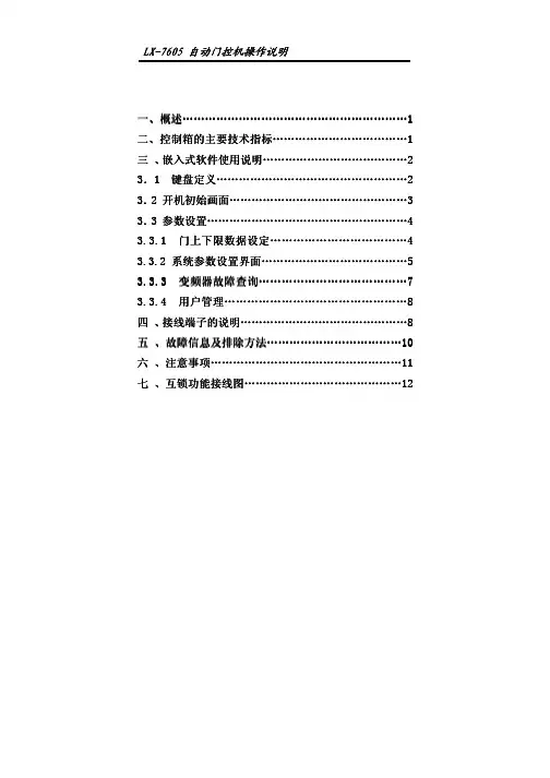
二、控制箱的主要技术指标控制箱的主要技术指标 (11)三 、嵌入式软件使用说明嵌入式软件使用说明..................................................................................................................2 3.1 1 键盘定义键盘定义键盘定义......................................................................................................................................................2 3.2 2 开机初始画面开机初始画面开机初始画面................................................................................................................................................33 3.3 3 参数设置参数设置参数设置..................................................................................................................................................................44 3.3.1 3.3.1 门上下限数据设定门上下限数据设定门上下限数据设定...................................................................................................44 3.3.2 3.3.2 系统参数设置界面系统参数设置界面系统参数设置界面..................................................................................................................5 3.3.3 3.3.3 变频器变频器变频器故障查询故障查询故障查询.....................................................................................................................77 3.3.4 3.3.4 用户管理用户管理用户管理................................................................................................................................................88 四 、接线端子的说明接线端子的说明 (88)五 、故障信息及排除方法故障信息及排除方法 (101010)六 、注意事项注意事项 (111111)七 、互锁功能接线图互锁功能接线图 (121212)z z z Ps g i ol e P f r1.机械限位和编码器可以随意选择。
长风自动门说明书一、产品概述长风自动门是一种智能化的门控产品,采用先进的技术和高质量的材料制造而成。
它具有打开和关闭门的自动功能,能够根据用户的需要进行灵活的设置和调整。
长风自动门广泛适用于商业建筑、公共场所、住宅小区等场所,为用户提供便捷、安全、舒适的出入口环境。
二、产品特点1.智能感应:长风自动门配备了先进的感应器,能够根据人员位置和距离自动感知并打开门,无需手动操作。
2.安全保护:长风自动门具有多重安全保护功能,包括紧急停止、防撞保护和防夹保护等,以保障用户的安全。
3.静音设计:长风自动门采用特殊的设计和材料,具有良好的降噪效果,保证用户在使用过程中不会受到噪音的干扰。
4.节能环保:长风自动门采用高效的能源管理技术,具有低功耗和高能效的特点,为用户提供节能环保的使用体验。
5.操作简便:长风自动门配备了直观的人机界面,使用简单易懂的操作方式,方便用户进行设置和调整。
三、使用方法1.安装:请参考长风自动门安装手册,按照要求进行正确的安装。
安装完成后,请仔细检查各个部件是否安装牢固,确保门的运行安全。
2.开关电源:将长风自动门连接到电源,并打开电源开关。
此时,屏幕上会显示相应的开机画面。
3.设置参数:按照长风自动门操作手册的指引,进行系统参数的设置。
包括开门速度、感应距离等参数。
根据实际需要,进行相应的调整。
4.试运行:完成参数设置后,关闭门,然后手动推开门,观察是否能够正确感应到人员并打开门。
若有异常情况,请重新调整参数,直到正常运行。
5.日常使用:长风自动门在正常运行状态下,能够自动感应并打开门,用户只需轻推门即可进入。
在离开时,门会自动关闭。
如遇到特殊情况,用户可通过手动按钮来进行打开和关闭门的操作。
四、注意事项1.请勿在门上进行攀爬或悬挂重物,以免影响门的正常运行。
2.在使用长风自动门时,应保持门周围的通道畅通,避免杂物阻碍感应器的正常工作。
4.请勿将长风自动门暴露在阳光、雨雪等恶劣天气中。
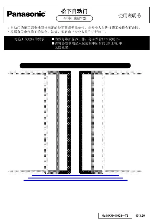
自动门的施工请委托我社指定的经销商或专业单位。
非专业人员进行施工操作会有危险。
根据有关电气施工的法令、法规,务必由“专业人员”进行施工。
松下自动门使用说明书平移门操作器对施工代理店的要求... ●为做好维护保养工作,务必保管好本说明书。
●请将必要事项记入包装箱中所带的[保证书]中, 交给业主。
用户务必遵守的内容和种类用以下图示表示和说明。
此图表示不得进行的‘禁止’内容。
此图表示必须实行的 ‘强制性’内容。
施工作业时请勿让通行者通过自动门或靠近作业现场。
如工具或部件不慎坠落,会造成人员伤害。
请务必设置辅助光线传感器,确保门扇行走部位的检测范围。
否则会使通行者被门扇冲撞、夹击,造成伤害。
有关安全的注意事项警告 处理失误时,会产生令使用者死亡或负重伤的可能。
注意处理失误时,会产生令使用者受到伤害或发生物质上损失的可能性。
警告 Before accessing these terminals,WARNINGall power supply circuits must be disconnected.60588.52830Before accessing these terminals,WARNING all power supply circuits must bedisconnected.60588.528Before accessing these terminals,WARNINGall power supply circuits must be disconnected.60588.528注意请勿将门使用于潮湿、有振动、有腐蚀性气体产生的场所。
会造成火灾、触电、坠落等事故。
门在动作时,请勿切断电源。
会造成人员伤害。
Before accessing these terminals,WARNING all power supply circuits must bedisconnected.60588.52830请不要带电插拔。
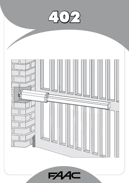
1FAAC S.p.A.Via Benini, 140069 Zola Predosa (BO) - ITALIATel.: 051/61724 - Fax: 051/758518www.faac.it732143 Rev.A.EC DECLARATION OF CONFORMITY FOR MACHINES ....................................................................................p. 2 WARNINGS FOR THE INSTALLER .......................................................................................................................p. 2 1.DESCRIPTION AND TECHNICAL SPECIFICATIONS ....................................................................................p. 31.1.DIMENSIONS ................................................................................................................................p. 32.ELECTRIC DEVICES (standard system) ....................................................................................................p. 33.INSTALLING THE AUTOMATED SYSTEM ......................................................................................................p. 43.1.PRELIMINARY CHECKS ................................................................................................................p. 43.2.INSTALLATION DIMENSIONS ........................................................................................................p. 43.2.1.GENERAL RULES FOR DETERMINING THE INSTALLATION DIMENSIONS ............................p. 43.3.INSTALLATION OF THE OPERATORS .............................................................................................p. 44.START-UP ....................................................................................................................................................p. 64.1.ADJUSTING THE ANTI-CRUSHING SYSTEM ..................................................................................p. 65.FINAL OPERATIONS ...................................................................................................................................p. 76.AUTOMATED SYSTEM TEST .........................................................................................................................p. 77.MANUAL OPERATION ...............................................................................................................................p. 78.RESTORING NORMAL OPERATION MODE ................................................................................................p. 79.MAINTENANCE ..........................................................................................................................................p. 710.REPAIRS .....................................................................................................................................................p. 711.TROUBLE SHOOTING .................................................................................................................................p. 821)ATTENTION! To ensure the safety of people, it is important that you readall the following instructions. Incorrect installation or incorrect use of the product could cause serious harm to people.2)Carefully read the instructions before beginning to install the product.3)Do not leave packing materials (plastic, polystyrene, etc.) within reachof children as such materials are potential sources of danger.4)Store these instructions for future reference.5)This product was designed and built strictly for the use indicated in thisdocumentation. Any other use, not expressly indicated here, could compromise the good condition/operation of the product and/or be a source of danger.6)FAAC declines all liability caused by improper use or use other than thatfor which the automated system was intended.7)Do not install the equipment in an explosive atmosphere: the presenceof inflammable gas or fumes is a serious danger to safety.8)The mechanical parts must conform to the provisions of Standards EN12604 and EN 12605.For non-EU countries, to obtain an adequate level of safety, the Standards mentioned above must be observed, in addition to national legal regulations.9)FAAC is not responsible for failure to observe Good Technique in theconstruction of the closing elements to be motorised, or for any deformation that may occur during use.10)The installation must conform to Standards EN 12453 and EN 12445.For non-EU countries, to obtain an adequate level of safety, the Standards mentioned above must be observed, in addition to national legal regulations.11)Before attempting any job on the system, cut out electrical power .12)The mains power supply of the automated system must be fitted with anall-pole switch with contact opening distance of 3mm or greater. Use of a 6A thermal breaker with all-pole circuit break is recommended.13)Make sure that a differential switch with threshold of 0.03 A is fittedupstream of the system.14)Make sure that the earthing system is perfectly constructed, andconnect metal parts of the means of the closure to it.15)The safety devices (EN 12978 standard) protect any danger areasagainst mechanical movement Risks , such as crushing, dragging,and shearing.16)Use of at least one indicator-light (e.g. FAACLIGHT ) is recommendedfor every system, as well as a warning sign adequately secured to the frame structure, in addition to the devices mentioned at point “15”.17)FAAC declines all liability as concerns safety and efficient operationof the automated system, if system components not produced by FAAC are used.18)For maintenance, strictly use original parts by FAAC.19)Do not in any way modify the components of the automated system.20)The installer shall supply all information concerning manual operationof the system in case of an emergency, and shall hand over to the user the warnings handbook supplied with the product.21)Do not allow children or adults to stay near the product while it isoperating.22)Keep remote controls or other pulse generators away from children,to prevent the automated system from being activated involuntarily.23)Transit through the leaves is allowed only when the gate is fully open.24)The user must not attempt any kind of repair or direct action whateverand contact qualified personnel only.25)Maintenance: check at least every 6 months the efficiency of thesystem, particularly the efficiency of the safety devices (including,where foreseen, the operator thrust force) and of the release devices.26)Anything not expressly specified in these instructions is not permitted.WARNINGS FOR THE INSTALLERGENERAL SAFETY OBLIGATIONSEC DECLARATION OF CONFORMITY FOR MACHINES(DIRECTIVE 98/37/EC)Manufacturer:FAAC S.p.A.Address:Via Benini, 1 - 40069 Zola Predosa BOLOGNA - ITALY Declares that:402 mod. operator,•is built to be integrated into a machine or to be assembled with other machinery to create a machine under the provisions of Directive 98/37/EC;•conforms to the essential safety requirements of the following EEC directives:73/23/EEC and subsequent amendment 93/68/EEC.89/336/EEC and subsequent amendment 92/31/EEC and 93/68/EECand also declares that it is prohibited to put into service the machinery until the machine in which it will be integrated or of which it will become a component has been identified and declared as conforming to the conditions of Directive 98/37/EC.Bologna, 01 January 2005The Managing DirectorA. Bassi3These instructions apply to the following models:402 CBC - 402 SBSThe FAAC 402 automated system for swing leaf gates consists of an enbloc composed of an electric pump and a hydraulic piston which transmits drive to the leaf.The model with a hydraulic locking does not require installation of electric locks, as it guarantees mechanical locking of the leaf when the motor is not operating.The model without a hydraulic locking, requires the installation of electric locks to ensure the leaf is mechanically locked.The 402 automated systems were designed and built to automate swing leaf gates. Do not use for any other purpose.Tab. 1: Technical specifications of “402 Operator”MODEL402 CBC402 SBSPower supply voltage 230 Vac(+6%-10%) 50 (6o) Hz Rod extension speed 1.3 cm/s 1 cm/s Pump flow rate1 l/min 0.75 l/min Traction and thrust force 0-500 daN0-690 daNOperating ambient temperature -40°C - +55°CAbsorbed power 220 W Absorbed current 1 A Motor rotation speed 1400 rpm Motor winding temperature 120°C Weight 6.5 kg Type of oil FAAC HP OILProtection class IP 55Single leaf max length 1,80 m3,00 mUse frequency55 (cycles/hour)4To ensure a correctly operating automated system, the structure of the existing gate or gate to be built must satisfy the following requirements:•Max length of leaves according to the dimensions of Table 1 on page 3.• A strong and rigid leaf structure.•Smooth, uniform leaves movement, without any irregular friction during the entire travel;•Existing hinges in good condition.•Travel limit mechanical stops must be provided.We advise you to carry out the metalwork jobs before installing the automated system.The condition of the structure directly influences the reliability and safety of the automated system.Table A : Recommended dimensions for standard operatorsc = The effective rod stroke is shorter than the maximum stroke, inorder to prevent the rod from reaching its stop point internally, during the opening and closing stages.(*) Rod effective stroke (**) maximum dimension1)Fasten the rear attachment on the pilaster, following the indications in Table A . Modify, if necessary, the length of the supplied attachment.Attention : To avoid compromising good operator functionality, we recommend you to respect the indicated dimensions.• For iron pilasters, accurately weld the rear attachment (ref.ባ, Fig. 6) directly on the pilaster.• For masonry pilasters, select one of the following solutions:A)appropriately lay a walling-in plate and then accurately weld the rear attachment.B)secure, with screws and expansion plugs, the rear attachment plate (ref. a, Fig.6) to the pilaster and then accurately weld the rear attachment to theplate as shown in Fig. 6.If the dimensions indicated in table A or B cannot be executed,the following must be considered in order to determine different measurements:-to obtain 90° opening of the leaf: a + b = c.-to obtain over 90° opening of the leaf: a + b < c.-lower a and b dimensions will result in higher speeds . We advise you to observe the current legal regulations;-limit the difference of the a and b dimensions to within 40 mm :higher differences will considerably vary speed during the opening and closing motion;-for reasons of operator dimensions, the minimum Z dimension is 50 mm (Fig. 4);-if the pilaster dimensions or the position of the hinge (dimension d ) do not make it possible to contain dimension a to the required size, a niche must be made in the pilaster as shown in Opening angle 90°110°a (mm)120100b (mm)120100c(*)(mm)240240d(**)(mm)705056-Lastly, remove the key and restore the power supply to the system.For any repairs, contact FAAC’s authorised Repair Centres.78The following table will help you identify and solve some particular conditions.CONDITIONGate not moving.Gate moving slowly.Gate moving jogwise.The operator is losing oil from the breather screw.The leaves stop at slow-down.Gate speed not constant.A B CD E FSUGGESTION-Check if mains power is supplied.-Make sure that the operator is not unlocked. (chapter 8.).-Check the adjustment of the anti-crushing system (paragraph 4.1).-Check oil level inside the tank. (chapter 9 - Fig. 16).-Check the connection and operation of the thrust capacitor.-Check the efficiency of the electronic control unit.-Check the adjustment of the anti-crushing system (paragraph 4.1).-Make sure that you have removed the breather screw (chapter 5).-Run some complete gate opening and closing cycles, in order to release any air inside the piston.-An initial, minimum oil leak is normal. A larger leak may occur if the operator is not fitted in a perfectly horizontal plane. If the oil leak does not stop soon, weadvise you to visit an authorised repair centre.-Check the adjustment of the anti-crushing system (paragraph 4.1).-Incorrect installation dimensions (paragraph 3.2).Notes919M A I N T E N A N C E R E G I S T E R.o N e t a D b o j f o n o i t p i r c s e D se r u t a n g i S 1_______________________________________________________________________________________________________________________________________na i c i n h c e T re m o t s u C 2_______________________________________________________________________________________________________________________________________na i c i n h c e T re m o t s u C 3_______________________________________________________________________________________________________________________________________na i c i n h c e T re m o t s u C 4_______________________________________________________________________________________________________________________________________na i c i n h c e T re m o t s u C 5_______________________________________________________________________________________________________________________________________na i c i n h c e T re m o t s u C 6_______________________________________________________________________________________________________________________________________na i c i n h c e T re m o t s u C 7_______________________________________________________________________________________________________________________________________na i c i n h c e T re m o t s u C 8_______________________________________________________________________________________________________________________________________na i c i n h c e T re m o t s u C 9_______________________________________________________________________________________________________________________________________na i c i n h c e T re m o t s u C 01_______________________________________________________________________________________________________________________________________na i c i n h c e T re m o t s u C I n s t a l l a t i o n t e c h n i c i a n ________________________________________________C u s t o m e r ___________________________________________________________________T y p e of s y s t e m ________________________________________________________S e r i a l n u m b e r _________________________________________________________I n s t a l l a t i o n d a t e ______________________A c t i v a t i o n ________________________S y s t e m c o n f ig u r a t i o nT R A P L E D O M RE B M U N L A I R E S e r o t a u t t A 402C A A F 1e c i v e d y t e f a S 2e c i v e d y t ef a S 1s l l e c o t o h p f o r i a P 2s l l e c o t o h p f o r i a P 1e c i v e d l o r t n o C 2e c i v e d l o r t n o C lo r t n o c o i d a R pm a l g n i h s a l F ec i v ed re h t O ec i v ed re h t O I n d i c a t i o n of r e s i d u a l r i s k s a n d o f f o r e s e e a b l e i m p r o p e r u s e_________________________________________________________________________________________________________________________________________________________________________________________________________________________________________________________________________________________________________________________________________________________________________________________________________________________________________________________________________________________________________________________________________________________________________________________________________________________________________________________________________________________________________________________________________________________________________________________________________________________________________________________________________________________________________________________________________________________________Read the instructions carefully before using the product and store them for future useIf correctly installed and used, the 402 automated system ensures a high degree of safety.Some simple rules on behaviour can prevent accidental trouble:-Do not pass between the leaves when they are moving. Waitfor the leaves to open fully before passing through them.-Do not, on any account stay in between the leaves.-Do not stand near the automated system, and do not allowchildren, persons or things to do so, especially when it is operating.-Keep remote controls or other pulse generators away fromchildren, to prevent the automated system from being activated involuntarily.-Do not allow children to play with the automated system.-Do not willingly obstruct leaves movement.-Prevent any branches or shrubs from interfering with leavesmovement.-Keep indicator-lights efficient and easy to see.-Do not attempt to activate the leaves by hand unless you havereleased them.-In the event of malfunctions, release the leaves to allow accessand wait for qualified technical personnel to do the necessary work.-When you have set manual operation mode, cut power to thesystem before restoring normal operation.-Do not in any way modify the components of the automatedsystem.-Do not attempt any kind of repair of direct action whateverand contact qualified personnel only.-At least every six months: arrange a check by qualifiedpersonnel of the automated system, safety devices and earth connection.These instructions apply to the following models:402 CBC - 402 SBS.The FAAC 402 automated system for swing leaf gates consists of a hydraulic enbloc composed of an electric pump and a hydraulic piston which transmits drive to the leaf.The models with a hydraulic locking do not require installation of an electric lock, as they guarantee mechanical locking of the leaf when the motor is not operating.The other models, without a hydraulic locking always require one or more electric locks to ensure the leaf is mechanically locked.Leaves of up to 3 mt can be automated depending on the selected model.The functioning of the operators is controlled by an electronic control unit, housed in an enclosure with adequate degree of protection against atmosphere agents.The leaves are normally closed.When the electronic control unit receives an opening command from the radio control or any other pulse generator, it activates the hydraulic appliance which rotates the leaves until they reach the opening position to allow access.If automatic mode was set, the leaves close automatically after selected pause time has elapsed.If the semi-automatic mode was set, a second pulse must be sent to close the leaf again.A stop pulse (if supplied) always stops movement.For details on the behaviour of the automated system in different function logics, consult the installer.Automated systems include safety devices (photocells) that prevent the leaves from moving when there is an obstacle in the area they protect.The 402 automated system is supplied standard with a hydraulic anti-crush protection safety device (BY-PASS) which limits the torque transmitted to the leaves.The warning-light indicates the current leaf movement.If the gate has to be moved manually due to a power cut or fault of the automated system, use the release device as follows:-Insert the triangular key on the release screw located in the lower part of the flange (Fig.1).-Turn the release key anti-clockwise for about two turns.-Open or close the leaf manually.To prevent an involuntary pulse from activating the operator during the manoeuvre, cut power to the system before re-locking the operator.-To re-lock the operator, turn the key clockwise until it stops (Fig.1).-Release the operator from the front and rear attachments.732143 - Rev. A。

2023年智能家庭自动门系统安装与使用手册本手册将会为您提供有关智能家庭自动门系统的全面安装与使用资料。
在阅读本手册之前,请确保已经购买了智能家庭自动门系统。
第一部分:安装在开始安装之前,请阅读以下安全操作的说明。
1. 务必断电在安装过程中,首先需要确认门的电源已经断开。
为了确保安全,最好是将电源熔断器相应的拔出来,确保门的电气系统处于绝缘状态。
此外,对于不同类型的电气系统,需要选择相应的工具进行安装和维护。
2. 确认门的尺寸和位置在安装和布线之前,需要确保门的厚度和位置,以便安装区域周围没有任何物品挡住门的移动。
在安装过程中,需要注意门与安装墙面之间的有效距离,以避免安装误差。
3. 检查门的零部件在安装过程中,需要仔细检查门的各个零部件,以确保零部件安装位置正确,零件间隙正确,零部件连接牢固,防止安装过程中零部件脱落和误操作等情况,从而提高门体安全性和使用寿命。
4. 安装控制系统安装完成后,需要安装门控制系统和配电盘。
在安装前,需要先准确测量门的长度和高度,将有关部件安装到计划的位置上。
然后将控制器和电池连接起来,测试门体开启和关闭的速度以及动作的方向是否正确。
按照操作手册的说明进行连接和设置。
5. 安装电源在接通电源前,确认所有的排线都正确连接,没有接错或扭曲的现象,以免对智能家居自动门控制系统造成危害。
第二部分:使用在安装完毕后,请遵守以下使用说明。
1. 监测系统您需要通过检查来确保系统不会出现故障或技术难题。
如果发现任何异常情况,请立即联系维护人员查询问题。
定期检查门和系统,以便提前发现局部故障并及时加以修复。
2. 刷卡开门系统使用了智能刷卡开门控制,您可以自由选择使用 IC 卡或 ID 卡开门。
刷卡,门就会自动打开,方便快捷。
3. 安全照明系统系统配备了中央控制可调 LED 照明系统,您可以通过按键或远程设置照明的暗度,以适应不同的环境和场景。
照明系统可以为您提供更安全的门控服务。
4. 上锁控制您可以通过控制系统设置门的状态,包括打开状态和关闭状态。
商场自动门维护安全操作手册一、前言商场自动门为顾客提供了便捷的通行体验,但为了确保其安全可靠运行,定期的维护至关重要。
本操作手册旨在为维护人员提供详细、清晰的指导,以保障商场自动门的正常运行和顾客的安全。
二、自动门类型及工作原理商场常见的自动门主要有平移式自动门和旋转式自动门。
平移式自动门通过传感器检测到人员接近时,控制系统驱动电机带动门体沿轨道平移开启,人员通过后再自动关闭。
旋转式自动门则是通过电机驱动门体围绕中心轴旋转,实现人员的进出。
三、维护前的准备工作1、维护人员应具备相关的电气知识和机械维修技能,熟悉自动门的结构和工作原理。
2、准备好必要的工具,如扳手、螺丝刀、万用表、清洁剂等。
3、在维护前,应设置明显的警示标识,防止他人误操作自动门。
四、安全注意事项1、维护时必须切断自动门的电源,以防止触电事故。
2、在进行机械部件维修时,要确保门体处于稳定状态,防止意外移动造成伤害。
3、高空作业时,必须佩戴安全带和安全帽。
五、日常维护内容1、外观检查每天对自动门的外观进行检查,查看门体表面是否有划伤、变形、腐蚀等情况。
如有问题,及时进行修复或更换部件。
2、传感器清洁定期清洁传感器表面的灰尘和杂物,以确保其正常感应。
使用干净的软布轻轻擦拭,避免使用湿布或腐蚀性清洁剂。
3、轨道清洁与润滑清理轨道内的杂物和灰尘,检查轨道是否平整,有无变形。
然后涂抹适量的润滑油,以减少门体运行的阻力。
4、皮带和链条检查检查皮带和链条的松紧度,如有松弛,及时调整。
同时查看是否有磨损、裂纹等情况,必要时进行更换。
5、电气连接检查定期检查电气连接是否牢固,有无松动、氧化等现象。
如有问题,及时紧固或更换连接件。
六、定期维护内容1、电机检查每半年对电机进行一次检查,包括电机的运行声音、温度、电流等参数。
检查电机的电刷磨损情况,必要时进行更换。
2、控制系统检测每年对控制系统进行一次全面检测,检查控制板上的电子元件是否正常,程序是否运行稳定。
0 目录0 目录-------------------------------------------------------11 简介-------------------------------------------------------12 技术描述---------------------------------------------------53操作特性--------------------------------------------------164维护保养--------------------------------------------------205简单故障排除----------------------------------------------21附录------------------------------------------------------251 简介1.1 安全操作1.2 前言1.3 版权1.4 使用须知1.5 专业名词缩写1.6 选装部件1.1 安全操作美必盛自动门的设计、检验和生产是依据严格的国际标准进行的。
进行每年一次的常规维护时应确保操作程序正确(在经常使用的情况下)。
所有的工作必须由美必盛公司或美必盛公司认可的经销商来完成。
在进行操作之前必须先阅读操作手册。
警告:尽量避免接触转动部分。
如果对操作手册有任何疑问,请与宁波美必盛公司联系。
美必盛自动门地址:联系电话:网址:1.2 前言操作手册是专门为自动门的用户提供的,它向你提供如下信息:门的操作门的结构门的维护1.3 版权本操作手册是由公司提供和认可的。
它只提供给自动门的所有者和公司认可的代理商。
公司保留一切权力。
本操作手册信息的所有权归美必盛公司。
在没有得到美必盛公司的书面认可之前,将本操作手册的信息或其中的一部分泄漏给第三者是不允许的。
美必盛公司保留改进产品而不另行通知的权力。

ECO Series AUTOMATIC DOOR SYSTEM1、Using permanent magnet DC motor drives, more stable performance, and high precision .2、Smooth operation even with high speeds.3、Pre-adjusted and tested in the factory with self-learning functions for opening and closing speed.No extra works for additional adjustments in the jobsite make theinstallation works fast and easy.saving space and flexible installation.4、Lower energy consumption.TYPE: ECO 02/C 中分轿门TYPE: ECO 02/CTwo Panels Center Opening Car DoorTYPE: ECO 02/R-L旁开轿门TYPE: ECO 02/R-LTwo Panels Telescopic Opening Car DoorOSCAR O SeriesAUTOMATIC DOOR SYSTEM1、Using AC VVVF motor drive, controlled by Panasonic VVVFdoor inverter.2、It utilizes the synchronous belt drive, low noise.3、Strong resistance of electromagnetic interference.4、Speed, position and torque adjustable for opening andclosing curve.5、Towed truck with mechanical anti-derailment devices.TYPE: OSCAR 02/CPL 60065070075080085090095010001050110011501200D162/D2217/D3/225A 1290134013901560166017101890194019902190224022902340B211271296361436中分轿门TYPE: OSCAR 02/CTwo Panels Center Opening Car DoorOSCAR 系列自动门AUTOMATIC DOOR SYSTEM标准配置不含轿门锁 Standard configuration are not including the car door lock.接受特殊规则定制 Accept for special size Customized.ECO 中分门机OSCAR中分门机中分层门TYPE: 01/CTwo Panels Center Opening Landing DoorECO/OSCAR 系列自动门AUTOMATIC DOOR SYSTEMTYPE: 01/C• TYPE:01/C 层门同时适用ECO、OSCAR 系列门机。
引言概述自动门控制器是一种用于控制自动门运行的设备,广泛应用于商业和公共场所,以提供方便和安全的出入口服务。
本文将为用户提供一份详细的自动门控制器用户指南,旨在帮助用户更好地理解和操作自动门控制器。
正文内容一、自动门控制器的基本原理1.1电动机驱动原理1.2传感器检测原理1.3控制器信号处理原理1.4安全系统原理1.5手动开关和远程控制原理二、自动门控制器的功能介绍2.1开门和关门控制功能2.2自动开门和自动关门功能2.3电源管理功能2.4报警和安全保护功能2.5远程监控和访问控制功能三、自动门控制器的安装与设置3.1控制器安装位置选择3.2电源接入及线路布置3.3传感器安装与调试3.4控制器参数设置3.5门体检测和调试四、自动门控制器的常见故障与排除4.1电源故障及排除方法4.2电机无法运转的故障及排除方法4.3传感器失灵的故障及排除方法4.4控制器无反应的故障及排除方法4.5其他常见故障及排除方法五、自动门控制器的安全使用与维护5.1安全使用操作指南5.2定期检查和维护工作5.3警示标志和标识的设置5.4故障时的应急措施5.5专业维修和保养建议总结通过本文,我们为用户提供了一份详细的自动门控制器用户指南。
我们从基本原理、功能介绍、安装与设置、常见故障与排除以及安全使用与维护等方面对自动门控制器进行了全面的介绍。
希望本文可以帮助用户更好地理解并使用自动门控制器,并为用户提供便利和安全的出入口服务。
用户在使用过程中如遇到问题或困难,可以参考本文提供的排除方法或专业维修建议进行解决。
新韩自动门说明书1. 简介新韩自动门是一款高品质、高安全性的自动门系统。
本说明书将详细介绍新韩自动门的特点、功能、安装步骤以及使用注意事项,帮助用户正确使用和维护自动门,确保其长久的正常运行。
2. 特点与功能2.1 特点•高品质:新韩自动门采用优质材料制造,严格按照国际标准进行生产,确保产品质量可靠。
•高安全性:配备先进的安全传感器和防夹功能,确保使用过程中不会造成人员伤害。
•静音设计:采用先进的减震技术和静音驱动系统,开关过程中噪音极低。
•节能环保:采用智能控制系统,能够根据实际需求调整开关速度和工作时间,节约能源。
2.2 功能•自动感应开关:通过红外线传感器或微波雷达感应到人员接近时,自动打开或关闭门体。
•手动开关模式:可通过按钮手动控制门体的开启和关闭。
•多种开关方式:可根据用户需求设置不同的开关模式,如常开、常闭、半开等。
•自动锁定功能:门体关闭后自动锁定,确保安全性。
•防夹功能:配备多重防夹传感器,可感知到门体周围的障碍物,避免夹伤事件发生。
•过载保护:当门体受到外力撞击或超载时,自动停止运行以保护设备和人员安全。
3. 安装步骤3.1 准备工作在安装新韩自动门之前,请确保以下准备工作已完成: 1. 根据施工图纸确定安装位置,并确保该位置没有任何障碍物。
2. 检查电源是否符合要求,并准备好所需的电缆和配件。
3. 确保具备安装所需的工具和设备。
3.2 安装步骤1.固定地轨:根据施工图纸确定地轨位置,在地面上进行固定。
2.安装门扇:将门扇与地轨连接,并确保门扇能够顺畅运行。
3.连接控制系统:将控制系统与门扇连接,并按照说明书进行正确接线。
4.安装感应器:根据需要选择红外线传感器或微波雷达感应器,并按照说明书进行正确安装。
5.连接电源:将电源线连接到控制系统,并确保电源接地良好。
6.调试测试:完成以上步骤后,对自动门进行调试测试,确保各项功能正常。
4. 使用注意事项为了确保使用新韩自动门的安全和正常运行,请注意以下事项: 1. 请勿将手指、衣物等放在门扇运行区域内,以免夹伤。
CANCELLI AUTOMATICI1425mmProcedura di montaggio) Svitare la vite di regolazione e togliere l’attacco di coda dalla guida di scorri-mento dell’automazione.) Estrarre la catena con il rinvio e l’at-tacco di testa dalla guida.) Sganciare la catena dal giunto e pro-lungarla con la parte in dotazione.ENGLISHAssembly procedure1) Remove the adjustment screw andthe end coupling from the slide guide.2) Extract the chain with the transmis-sion and the head coupling from theguide.3) Unfasten the chain from the joint andextend it with the piece povided.FRANÇAISProcédure de montage1) Dévisser la vis de réglage et enleverle raccord de queue du rail de l’automa-tisme.2) Extraire la chaîne avec le renvoi et leraccord de tête du rail.3) Décrocher la chaîne du joint et larallonger avec la partie fournie de série.) Die Einstellschraube lösen und das Endanschlussstück aus der Laufschie-ne des Automatiksystems entfernen.) Die Kette mit dem Vorgelege und das Endanschlussstück aus der Schiene) Die Kette aus dem Gelenk aushaken und mit dem mitgelieferten T eil verlän-ESPAÑOLProcedimiento de montaje1) Desenrosque el tornillo de regulacióny quite el enganche del extremo de laguía de deslizamiento de la automatiza-ción.2) Extraiga la cadena con la transmisióny el enganche del extremo de la guía.3) Desenganche la cadena del acopla-miento y alárguela con la parte entre-gada.NEDERLANDSMontageprocedure1) Draai de stelschroef los en verwijderhet koppelstuk aan de staartzijde van deloopgeleider van de automatisatie.2) Verwijder de ketting met transmissie-stuk en het koppelstuk aan de kopzijdevan de geleider.3) Maak de ketting los uit het koppelstuken maak ze langer met behulp van debijgeleverde uitrusting.Prolunga - Extension - RallongeVerlängerung - Prolongación -Staffa di giunzione - Joining bracket - Bride de jonctionVerbindungsbügel - Estribo de unión- SamenvoegbeugelCatena - Chain - Chaîne Kette - Cadena - KettingCANCELLI AUTOMATICICAME CANCELLI AUTOMA D OSSON ASIER (TREVISO (+39) 0422 4940 (+39) 0422 4941A N UMERO 800 295830。
自动门控制器用户指南1、技术规格2、基本功能设置3、特殊功能设置4、错误代码5、连接设置6、操作设置7、其他1、技术规格控制器查看尺寸: 323 * 60 (毫米)电路板尺寸: 340 * 56 (毫米)2、基本功能设置按[菜单]按钮将会出现基本功能设置模式。
继续按[菜单]按钮功能设置模式将改变,并显示出来。
然后按[向上]或[向下]按钮来变更设定值,按[设置]按钮储存这个值。
此后,基本功能设置模式会在5秒后自动消失。
3、特殊功能设置按[设置]按钮超过3秒钟将会出现特殊功能设置模式。
其菜单可以按[菜单]按钮改变,然后按[向上]或[向下]按钮改变既定值,按[设置]按钮保存既定值。
此后,特殊功能设置模式会在5秒后自动释放。
预防大门打开的设置0:大门被迫打开时低速运行1:大门被迫打开时高速运行4、错误代码自动门最初开放时显现。
E00:没有建立自动门设置E01:自动门的编码器出现问题E11:设置自动门的运行功率出现问题(问题发生在初始运行)EEE:因为严重的问题对构造的要求有需要时5、连接设置对于主控制器,连接外部的连接器划分如下:1 )电源连接器作为必须由专用电源提供的连接器,它输入AC24V2 )电机连接器这是一个4针的连接器供电的电动机,包括2引脚电机功率和2引脚电机锁。
3 )电机编码器作为连接器检查电机旋转,它为其独家使用而制造4 )外6针接线端子1 、直流12V输出2 、接地3 、打开4 、打开5 、外部安全传感器6 、外部安全传感器5 )安全传感器连接器利用其自身的安全传感器,自动门控制器配备有一个专用的连接器6 )下载连接这种自动门控制器配备有一个专用的连接器的升级程序6、操作设置1)自动门安装后接上电源,大门将按照初始设置检查其状态。
2)设置结束后,“ 〜哔”蜂鸣器声音会出现。
3)进入基本功能设置模式后按自动门[菜单]按钮,在第9 ,第10条和门的方向使用安全传感器。
如果其使用是不必要的或当前的大门方向是正确的,没有必要再设置。
自动门控制器用户指南自动门控制器用户指南1.引言1.1 目的本用户指南的目的是为了帮助使用自动门控制器的用户正确安装、操作和维护设备。
本指南将详细介绍自动门控制器的功能、操作步骤和常见问题解答,以确保用户能够充分利用该设备的各种特性。
1.2 范围本用户指南适用于所有型号的自动门控制器。
在阅读本文档之前,请确保已经详细了解您所使用的自动门控制器型号。
2.产品概述2.1 产品特性自动门控制器是一款用于控制自动门的电子设备。
其主要特性包括:- 可编程的开关时间间隔- 灵活的开门和关门方式设置- 多种安全功能,如红外线传感器和反向保护2.2 产品组成自动门控制器由以下组件组成:- 控制面板:用于设置和调整自动门的参数和功能。
- 传感器:用于检测门的开关状态和环境条件。
- 电源供应器:为自动门控制器供电。
3.安装步骤3.1 准备工作在安装自动门控制器之前,请确保已完成以下准备工作:- 确保所有必要的工具和设备已准备就绪。
- 关闭门的电源,并确保门处于关闭状态。
- 阅读安装手册并按照其中的指示进行操作。
3.2 安装控制面板按照以下步骤安装控制面板:1.找到合适的安装位置,确保控制面板与门的位置相对应。
2.使用螺丝刀固定控制面板,确保稳固安装。
3.连接控制面板与电源供应器,确保电源连接正确。
3.3 安装传感器根据自动门的类型和要求,安装相应的传感器。
一般来说,传感器应安装在以下位置:- 红外线传感器:将其安装在门的两侧,确保覆盖门的整个开闭范围。
- 反向保护传感器:将其安装在门的下方,确保能够及时检测到障碍物并关闭门。
4.操作指南4.1 基本操作使用自动门控制器进行基本操作,请按照以下步骤进行:1.按下电源按钮,确保控制面板已经启动。
2.调整开关时间间隔,可以通过控制面板上的菜单进行设置。
3.设置开门和关门方式,可以选择触发按钮、红外线传感器或定时器来进行设置。
4.2 安全功能自动门控制器配备了多种安全功能,以确保用户和门的安全。
格唯自动门控制器说明书安装危险:请安装在金属等阻燃的物体上,以避免发生火灾!请勿靠近可燃物品,以避免发生火灾!注意:不能让导线头或螺钉掉入其中避免引起控制器损坏!请将控制器安装在震动少,避免阳光直射的地方!请安装在能耐受其重量的场所,以避免掉落而受伤!开箱时发现控制器破损时,请不要安装!装箱单与实物名称不符时,请不要安装!搬运时应该轻拿轻放,否则有损害设备的危险!不要用手触及控制器的元器件,否则有静电损坏的危险!接线危险:必须遵守本手册的指导,由专业电气工程人员施工,以避免触电及伤害事故!控制器和电源之间必须有断路器隔开,否则可能发生火灾!请按标准对控制器进行正确规范接地,否则有触电危险!注意:绝不能将输入电源连接到控制器的输出端子(U、V、W)上。
注意接线端子的标记,不要接错线!否则引起控制器损坏!确保所配线路符合EMC要求及所在区域的安全标准。
否则可能发生事故!通讯线必须使用绞线绞距20~30mm的屏蔽双绞线,并且屏蔽层接地!确认产品的额定电压和交流电源的电压一致,以避免发生伤害事故及火灾!控制器的任何部分无须进行耐压试验,出厂时产品已作过此项测试,否则引起事故!上电危险:控制器必须盖好盖板后才能上电。
上电后不要打开盖板,不要触摸控制器的任何输入输出端子,否则可能引起触电!请勿随意更改控制器厂家参数。
否则可能造成设备的损害!非专业技术人员请勿在运行中检测信号,否则可能引起人身伤害或设备损坏!维护、检查和部件更换危险:请勿带电对设备进行维修及保养。
否则有触电危险!更换控制器后必须进行参数的设置,所有可插拔插件必须在断电情况下插拔!当维护和检查时要把输入电源断开,等待5分钟后再进行,以免触电。
Sliding door drive unit平滑门操作器KS1000Assembly-and operating instructions安装调试说明KBB Automated Entrances Inc.北京凯必盛自动门技术有限公司忠告《安装调试说明》明确了北京凯必盛自动门技术有限公司与用户之间就产品的质量保证责任,售后服务方面权利与义务产生和终止的约定。
请务必在使用本公司产品前认真阅读《安装调试说明》第一章概述1.1手册使用说明----------------------------------------------------------------------------------- 1.2产品说明----------------------------------------------------------------------------------------- 1.3应用范围----------------------------------------------------------------------------------------- 1.4技术参数----------------------------------------------------------------------------------------- 1.5安装所需工具------------------------------------------------------------------------------------ 1.6安装流程图---------------------------------------------------------------------------------------第二章基础安装2.1 安装形式------------------------------------------------------------------------------------------- 2.2 安装条件------------------------------------------------------------------------------------------- 2.3 承重梁的安装-------------------------------------------------------------------------------------第三章安装操作器3.1 安装挂轮组件------------------------------------------------------------------------------------- 3.2 把门扇装在挂轮组件上------------------------------------------------------------------------- 3.3 承重梁上挡块的安装的安装-------------------------------------------------------------------- 3.4 防脱轮的调整-------------------------------------------------------------------------------------- 3.5 驱动器的安装-------------------------------------------------------------------------------------- 3.6 反向轮的安装-------------------------------------------------------------------------------------- 3.7 组装皮带和皮带夹--------------------------------------------------------------------------------3.4 齿形皮带的安装---------------------------------------------------------------------------------- 3.5 主控器的安装------------------------------------------------------------------------------------- 3.6 控制器的安装-------------------------------------------------------------------------------------第四章通电调试4.1 运行前准备---------------------------------------------------------------------------------------- 4.2 电气设定------------------------------------------------------------------------------------------- 4.3 系统启动------------------------------------------------------------------------------------------- 4.4 自检过程的中断----------------------------------------------------------------------------------第五章操作器实现的功能5.1 概述------------------------------------------------------------------------------------------------- 5.2 PSA控制器(可选件)------------------------------------------------------------------------- 5.2.1 操作功能(第一级)----------------------------------------------------------------- 5.2.2 设定功能(第二级)----------------------------------------------------------------- 5.2.3 编程功能(第三级)----------------------------------------------------------------- 5.2.4 故障显示功能(第四级)----------------------------------------------------------- 5.3安全保护装置-----------------------------------------------------------------------------------5.4操作器主要的输入与输出端子功能-------------------------------------------------------- 5.5互锁功能----------------------------------------------------------------------------------------- 5.6注意细节----------------------------------------------------------------------------------------- 第六章维护与故障排除6.1 安全责任------------------------------------------------------------------------------------------- 6.2维护------------------------------------------------------------------------------------------------ 6.3故障排除-------------------------------------------------------------------------------------- --- 6.4KS1000零部件清单---------------------------------------------------------------------------- 6.5环保处理--------------------------------------------------------------------------------------- --附图附图1:盖板安装图------------------------------------------------------------------------------------ 附图2、两翼门安装图--------------------------------------------------------------------------------- 附图3、左开门的安装图------------------------------------------------------------------------------ 附图4、右开门的安装图------------------------------------------------------------------------------ 附图5、主控器接线图--------------------------------------------------------------------------------- 附图6、电池电子机械锁接线图--------------------------------------------------------------------- 附图7、启动信号接线图------------------------------------------------------------------------------第一章概述1.1手册使用说明●手册对门的安装、调试、维护及故障排除进行了准确说明。