关于三相变频电源的外文资料翻译
- 格式:doc
- 大小:95.00 KB
- 文档页数:7
变频器工作原理外文文献翻译、中英文翻译外文资料Converter working principleMain circuit is for induction motors provide voltage variable frequency power source power conversion part, the inverter main circuit in general can be divided into two categories [1]: voltage is voltage source DC converter for AC inverter, the DC loop filter is capacitance. Current model is the current source of the direct streamization AC inverter, the DC circuit filter inductance. It consists of three parts, the power supply conversion for DC power rectifier, absorption produced in converter and inverter voltage ripple "flat wave circuit, and DC power converter for AC power" inverter ".(1) rectifier: Recently a lot of use is diode converter, it is the power supply conversion for the DC power supply. Also available two groups of transistor converters constitute a reversible converter, due to its power direction reversible can regeneration operation.(2) the flat wave circuit: in the rectifier DC voltage, containing 6 times the frequency of power supply ripple voltage, furthermore the inverter produces a pulsating current the DC voltage changes. In order to suppress the voltage fluctuation, the inductance and capacitance absorption pulsating voltage (current). Device volume hours, if power supply and a main circuit component in margin can save inductance of the simple flat wave circuit.(3) inverter: Contrary to rectifier, inverter is the DC power conversion is the desired frequency AC power and to determine the time the six switch device turn-on and off you can get 3 phaseAC output. By voltage type PWM converter as exemplifying the switching time and voltage waveform.Control circuit is to provide a loop control signal to the asynchronous motor power supply (voltage, frequency) of the main circuit, the frequency, the voltage "operation circuit", the main circuit of the "voltage and current detection circuit, the motor" speed detection circuit, operation circuit of control signal amplification drive circuit ", and the inverter and the motor" protection circuit.(1) arithmetic circuit: the external speed, torque and other instructions with the detection circuit of the current, voltage signal comparison operation, determine the output voltage of the inverter, frequency.(2) voltage, current detection circuit: with the main circuit potential isolation detection voltage, current and so on.(3) driving circuit, driving circuit of main circuit devices. It and control isolation circuit enable device in the main circuit turn-on, turn off.(4) speed detection circuit installed in asynchronous motor shaft machine speed detector (TG, PLG) signal for speed signal into the computing circuit, according to the instruction and operation can make the motor run in the speed command.(5) protection circuit: detection of the main circuit of the voltage, current and so on, when the occurrence of overload or over voltage, etc., in order to prevent the inverter and asynchronous motor damage, so that the inverter to stop working or inhibit voltage, current value.中文翻译变频器工作原理主电路是给异步电动机提供调压调频电源的电力变换部分,变频器的主电路大体上可分为两类[1]:电压型是将电压源的直流变换为交流的变频器,直流回路的滤波是电容。
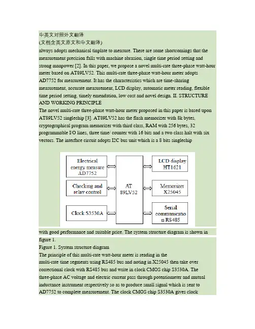
中英文对照外文翻译(文档含英文原文和中文翻译)always adopts mechanical tinplate to measure. There are some shortcomings that the measurement precision falls with machine abrasion, single time period setting and strong manpower [2]. In this paper, we propose a novel multi-rate three-phase watt-hour meter based on AT89LV52. This multi-rate three-phase watt-hour meter adoptsAD7752 for measurement. It has the characteristics which are time-sharing measurement, accurate measurement, LCD display, automatic meter reading, flexible time period setting, timely emendation, low cost and novel design. II. STRUCTURE AND WORKING PRINCIPLEThe novel multi-rate three-phase watt-hour meter proposed in this paper is based upon AT89LV52 singlechip [3]. AT89LV52 has the flash memorizer with 8k bytes, cryptographical program memorizer with third class, RAM with 256 bytes, 32 programmable I/O lines, three time/ counter with 16 bits and a two class halt with six vectors. The interface circuit adopts I2C bus unit which is a 8 bits singlechipwith good performance and suitable price. The system structure diagram is shown in figure 1.Figure 1. System structure diagramThe principle of this multi-rate watt-hour meter is reading in themulti-rate time segments using RS485 bus and noting in X25045 then take over correctional clock with RS485 bus and write in clock CMOS chip S3530A. Thethree-phase AC voltage and electric current pass through potentiometer and mutual inductance instrument respectively so as to produce small signal which is sent toAD7752 to complete measurement. The clock CMOS chip S3530A gives clockinformation per second in the course of automatic move and analyze this clock belongs to which period of time according to advance periods of time set in X25045 then save the electrical energy in RAM memorizeraccording to corresponding period of time. We write it to corresponding address ofX25045 when the electrical energy achieves one degree in order to make the multi-rate measurement come true. This watt-hour meter hasfunctions of clear LCD display, missing phase detection, burthen control, halt electricity check and storage, automatic meter reading and so on.III. THE DESIGH OF HARDWARE CIRCUITA. Electrical energy measurementThe three-phase electrical energy measurement is realized by the low consume CMOS chip AD7752 of ADI company. The inside of AD7752 adopts digital circuit besides ADC, filter and multiplication circuit which can eliminate noises effectively. The sampling course of voltage and electric current in three-phase AC power supply loop is shown in figure 2 in which IA stands for voltage sampling of A phase. The sampling circuits of B phase and C phase are similar to A phase. The power after integral is transformed to electrical pulse for output. The pulse of fan-out CF enters into interregnum INT0 of AT89LV52 through photoelectricity insulation 4N25. CPU measures the electrical energy [4]. We adjust the pulse number of CF by combining the state of S1 and S2. The connection of electrical energy and pulse is W = M C . In which, W is the electrical energy with the unit of kilowatt-hour, M is the total pulse number,C is the pulse number of ammeter. We choose C equals to 3000 that is to say every kilowatt-hour is 3000pulses.Figure 2. Circuit schematic diagramof watt-hour meterB. LCD displayThe LCD display [6] adopts HT1621 CMOS chip of HOLTEK Company toachieve twelve bits digital display. HT1621 is the LCD drivers with 128 segments (32×4) inner memorizer. The interior of HT1621 consists ofcontrol and time circuits, RAM, LCD drive and watch timer. It hasthe merits of small volume and low cost so that it is suit to watt-hour meter. We use serial interface which only has four lines between HT1621 and AT89LV52. The detailed connection is shown in figure 3. P20, P21, P22 and P23 of AT89LV52 connect to CS, RD, WR and DATA respectively with the use to refurbish the display of RAM. HT1621 drive CMOS chip has 48 nodes in which COM0, COM1, COM2, COM3 connect to the communal end and drive output of LCD and SG0, SG1, SG2, SG3 connect to drive output of every segment respectively. In addition, an adjustable resistance of 20kΩ is put between VDD and VLCD to adjust the display contrast of LCD. Experiment shows that the contrast is better with VDD=5V and VLCD=4V. C. Serial memorizerSerial memorizer adopts low power consumption chip X25045 of XICORcompany .It has three functions which are watchdog timer WTD, voltage supervision and serial memorizer E2PROM with 512 bytes. WTD can be set 200ms, 600ms and 1400ms time intervals. The software program is read into X25045. During the normal running of program, WTD receives the trigger signal in time intervals in order to ensure the normal running of program. X25045 will output a high potential through RESET line if WTD does not receive trigger signal in time intervals. The trigger watt-hour meter reset in order to prevent program flying away. As the serial memorizer chip, 512 bytes of X25045 are used to storage the watt-hour meter code, multi-rate periods of time, the apex electricity, smooth electricity, vale electricity and total electricity of last month and this month. Storage can be divided into two same areas. One is used as data storage. The other is used for backup. The number of storagecan be revised 100,000 times. Data can be stored for 100 years. It is connected withAT89LV52 by SPI agreement bus. The connection is shown in figure 3.D. Clock circuitThe clock circuit is completed by S3530A chip. It is a low powerconsumption clock chip that supports I2C Bus. It sets the clock and calendar according to the data received by CUP communicating with RS485. At the same time, it continues to walk time by its own oscillation. The crystaloscillator of 32.768 kHz is put between Xin and Xout of S3530A which is connected with CPU through latching. SDA foot and SCL foot connect to P1.6 and P1.7 ofAT89LV52 respectively. There are two interrupt alarming foots can be set as second output or minute output synchronizing pulse which supply interrupt signal toAT89LV52 with one second period. Single-chip system will readout the current time through I2C communication interface according to this signal and calculate the period of time that this moment belongs to so as to realize the electrical energy measurement in different periods of time [5]. This clock circuit has spare lithium battery. The powersupply VCC supply power in normal wiring and electrified for lithium battery of 3.6V. When there is power off, the system will automatically convert lithium battery to clock circuit for power supply. The clock will still running accurately even the power is off.Figure 3. Partial circuit figure of watt-hour meterE. RS485 CommunicationMAX485 chip can implement RS485 communication control ofmulti-rate watt-hour meter. MAX485 chip has RS485 communication protocol. It can take 128 hypogenous computers. Its transmission distance is greater than 1km and its transfer rate is up to 250kb per second. The watt-hour meter connects with the unit controller through the RS485 bus. Each unit has a cell controller can manage 128 multi-rate watt-hour meter. The cell controller connects to power management computer.Each watt-hour meter has one and only meter number with eight bits of hex. The electrician should write the user’s information and meter number and then import to the power management computer for initial installation so ad to complete the connection of user and management computer. Management computer sends setting of period of time and clock information with the manner of broadcast communication without address information. PC uploads information by the way of calling address. F. Lack Phase detection and relay controlIt can achieve relay control [7] with P27 of AT89LV52. P27 cancontrol relays using 4N25 photoelectricity isolator so as to complete powersupply and power control. Lack Phase detection gets the signal from fan-out of the relay and connects to 1 foot of photoelectricity isolator after passing a 75K resistance, the diode half-wave rectifier and capacitive filtering respectively. We detect the 4 foot of isolator to determine whether there is the lack of phase. If there is lack of phase, we detect again after 2 seconds overtime. We break off the power immediately if there is lack of power after the twice confirmation. In power protection circuit, it uses the INT1 interrupt foot of AT89LV52 to detect signal.When there is a sudden power off, INT1 jumps into a low voltage and the INT1 interrupt enters to the power protection program relying on the energy storage capacitor to save data. In the system, pulse output of AD7752, relay control port and the inputs of lack phase detection all use photoelectric isolator 4N25. It sends electrical signal by light coupling which can enhance the ability of anti-jamming. IV. THE DESIGN OF SOFTWAREA.The distribution of resourceThe software program includes main program, X25045 read and write program, RS485 serial communication program, interrupt serve program, timer handling program,HT1621 display control program, electrical energy measurement in different period of time and power down protection program, and system self-checking andanti-interference handling program. Interrupt resource distribution of system is: INT0 interrupt is used as AD7752 pulse measurement, INT1 as synchronization detecting, timer T0 as 100 ms timing, T1 as 1ms timing, and T2 as baud rate generator for serial communication program. RS485 asynchronous communication is set to receive interrupt and check information for sending.B. Module desighThe flow chart of main program is shown in figure 4. The watt-hourmeter should be able to initialize at each power up time. The initializing program includes setting working mode of timers, serial stomata and interrupts for AT89LV52,writing control word into X25045, S3530A and HT1621. This system sets three periods of time. The singlechip reads clock value from S3530A per second then analyze this clock belongs to which period of time according to advance periods of time set inX25045 then save the electrical energy in RAM memorizer according to corresponding period of time. We write it to corresponding address of X25045 when the electrical energy achieves one degree. The LCD display with 16 bits shows period of time and electrical energy information in turn. Figure 4. Flow chart of main program V. TESTING RESULTError measurement and running test have been made in Zibo Billion Electron Co., Ltd. The epigenous computer completes the setting of time management. There arethree-rate period of time. The first period of time is vale electricity from 00 point 00 minute to 06 point 30 minutes. The second period of time is apex electricity from 06 point 30 minutes to 22 point 30 minutes. The third period of time is smooth electricity from 22 point 30 minutes to 24 point 00 minute. The setting of rate period of time is sent to computer management system by electric power company according to national policy and saved in X25045. The apex electricity, smooth electricity, vale electricity and total electricity per month read saved in electrical energy meter and sent to epigenous computer through cell controller. The communication baud rate is 9600 bits per second. The checkout platform of 0.1 grade standard electronic power meter is used as standard meter and the multi-rate watt-hour meter is the tested meter. Billion Electron Company has carried out testing according to different load running. The measured data is shown in table 1 with the burthen of 30kW.TABLE I. COMPARE OF NORMAL METER AND TESTING METERThe testing result indicates that the error of this multi-ratewatt-hour meter is less than 1%, belongs to 1.0 grade. The return reading of electrical energy is precision and the emendation of time is timely and right. By testing, the method of decreasing errors for electricity metering can be obtained. Firstly, adjust the sampling resistance of AD7752 to accurate value. Secondly, the value of this resistance is needed less varying with temperature. Thirdly, during electricity metering progress, when mantissa portion of electricity is less than0.01, the remaining pulse should be accessed together, thus cumulative error caused by lack of 0.01degree energy loss could be avoided.VI. CONCLUSION AND EXPECTATIONThe multi-rate watt-hour meter achieves electrical energycomputation in different time according to different time setting. It adopts RS485 for serial communication and realizes automatic meter reading and real-time emendation. The results of production in Billion Electron Company showthat the multi-rate three-phase watt-hour meter proposed in this paper has the characteristics of novel design technique, accurate measurement, and flexible time period setting. Various technical indexes achieve the technique standard for national intelligent card watt-hour meter. Therefore, it has wide application. REFERENCES [1] Bu Zhengl iang, Yin Xianggen, Tu Guangyu. “Development of HV Watt-hour meter.” Automation of Electric Power Systems, 2006, 30(19): 89-93.[2] Kosukegawa M., Sakumoto Y. “Traceability system of electric energy standard and tendency in static watthour meter developmen t in Japan.” Sixth International Conference on Metering Apparatus and Tariffs for Electricity Supply, 1990,4: 259-263.[3] Xuehai Li. Applied tutorial of singlechip. Electronic industry publishing company, 2003.[4] Al-Khateeb Tarik, Blundel Martin. “An el ectronic meter for measuring the saving in electrical power.” The Ninth Arab International Conference on Solar Energy (AICSE-9), Kingdom of Bahrain, 2007,4 (209):328-333.[5] Liu Ying, Liu Qingyu. “Development of a self-calibration precision electricalmea suring meter.” Proceedings of the 1998 Conference Precision Electromagnetic Measurements, 1998,7:276.。
毕业设计(论文)外文资料翻译学院:专业:姓名:学号:外文出处:Electric Power Systems Research78(2008)276-289附件: 1.外文资料翻译译文;2.外文原文。
指导教师评语:签名:年月日附件1:外文资料翻译译文三相,电能质量改进的直/交变频器概要除了谐波功率和无功功率的其他来源,电力电子变频器的广泛使用大大影响着谐波的产生和在电力系统的无功潮流。
单相,电能质量改进的变频器在国内设计,开发和成功应用,商业和工业环境已经使三相,电能改进的变频器的设计和发展成为可能,而且它们广泛使用在不同的应用。
本文将对三相,电能改进的变频器配置,控制方法,对供应方和负载性能的输入功率因数计算,总谐波失真和完善管理,缩减波纹直流输出,额定功率,成本和特定应用选择做全面的探讨。
它还提供了国家在电能质量改善的变频器对工作在三相,开关式交直交变频器的研究人员,设计师和工程师而言最先进的技术。
内容1 说明交直交电源变频器广泛应用于各种应用,如电源供应器、直流马达驱动,调速交流驱动器、直流输出、开关电源前端变频器、实用接口与非传统能源来源。
在工艺技术,如焊接、电信系统的电源供应器、航空航天、军事环境等。
传统上,交直交电源变频器已主要由二极管或作为对电力系统非线性负载和在谐波的丰富,供应不足的功率因数的相控整流器作为借鉴,然而出现了配电网络和附近其他电器的整流系统的电能质量问题。
其他与这些变频器相关的问题包括:(1)从要求配电设备的处理大功率的电力系统大量无功功率由整流器得出,从而增加其伏安评级。
(2)电压在总线下降。
(3)较高的输入电流谐波导致扭曲的线电流,往往扭曲线电压波形。
这往往造成在同一总线上的敏感设备可靠运行的问题。
(4)在设备中增加损失(由于谐波)如变压器和电机连接到实际应用。
(5)与附近的通信线路电磁干扰。
(6)由于来自共振的高电压和电流与线路阻抗和电容故障,保险丝对电容器功率因数校正。
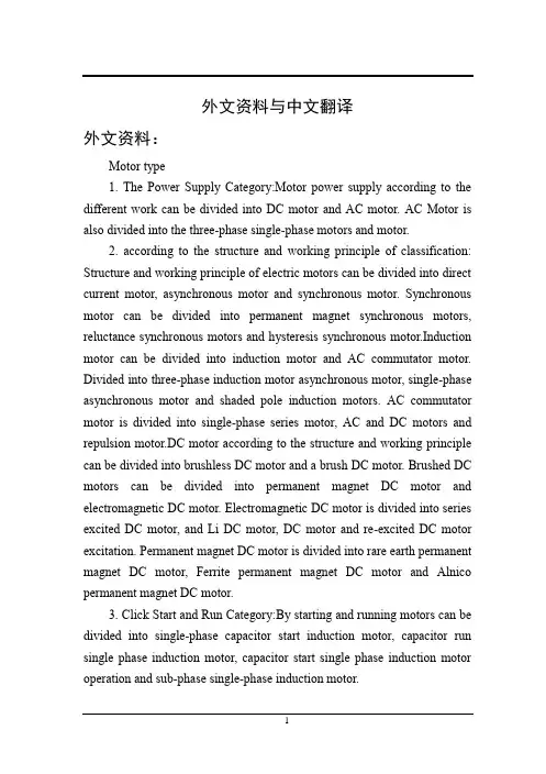
外文资料与中文翻译外文资料:Motor type1. The Power Supply Category:Motor power supply according to the different work can be divided into DC motor and AC motor. AC Motor is also divided into the three-phase single-phase motors and motor.2. according to the structure and working principle of classification: Structure and working principle of electric motors can be divided into direct current motor, asynchronous motor and synchronous motor. Synchronous motor can be divided into permanent magnet synchronous motors, reluctance synchronous motors and hysteresis synchronous motor.Induction motor can be divided into induction motor and AC commutator motor. Divided into three-phase induction motor asynchronous motor, single-phase asynchronous motor and shaded pole induction motors. AC commutator motor is divided into single-phase series motor, AC and DC motors and repulsion motor.DC motor according to the structure and working principle can be divided into brushless DC motor and a brush DC motor. Brushed DC motors can be divided into permanent magnet DC motor and electromagnetic DC motor. Electromagnetic DC motor is divided into series excited DC motor, and Li DC motor, DC motor and re-excited DC motor excitation. Permanent magnet DC motor is divided into rare earth permanent magnet DC motor, Ferrite permanent magnet DC motor and Alnico permanent magnet DC motor.3. Click Start and Run Category:By starting and running motors can be divided into single-phase capacitor start induction motor, capacitor run single phase induction motor, capacitor start single phase induction motor operation and sub-phase single-phase induction motor.4. by use classification:Motor driven by purpose can be divided into motor and control motor.Drive motor is divided into power tools (including drilling, polishing, polishing, grooving, cutting, reaming and other tools) with the motor, household appliances (including washing machines, electric fans, refrigerators, air conditioners, tape recorders, VCRs, DVD machines, vacuum cleaners, cameras, hair dryer, electric shaver, etc.) with General Motors and other small machinery and equipment (including a variety of small tools, small machinery, medical equipment, electronic equipment, etc.) electric motor.Stepper motor control is divided into motor and servo motors.5. The rotor structure by Category:Motor can be divided according to the structure of the rotor cage induction motor (the old standard called the squirrel cage induction motor) and the wound rotor induction motor (the old standard called Winding Induction Motor).6. classification of motor speed by running by running speed can be divided into high-speed motor, low speed motor, constant speed motor, speed motor. Low-speed motor is divided into gear motor, electromagnetic deceleration motor, torque motor, and claw-pole synchronous motors.In addition to speed motors can be divided into a class constant speed motor, motor level constant, there infinitely variable speed motor and variable speed motors, it can also be divided into electromagnetic speed motor, DC motor speed control, PWM frequency conversion motor and switch Reluctance Motor.Servo motor servo motor servomotor Automatic control device for the implementation of components of micro-special motor. Also known as the implementation of motor. Its function is to convert electrical signals into the shaft angular displacement or angular velocity.Servo motor points of AC and DC types. AC servo motor works the same with the AC induction motor. There are two phases in the stator spatial displacement of 90 ° angle and control winding field winding Wf WcoWftake a constant AC voltage applied to the Wc on the use of AC voltage or phase changes, to control motor operation purposes. AC servo motor has a stable, controllable, fast response, high sensitivity and mechanical properties and regulation characteristics of the nonlinearity index strict (requiring less than 10%, respectively 15% and less than 15% ~ 25%), etc. characteristics. DC servo motor works the same with the general DC motor. Change Ua or change φ, can control the DC servo motor speed, but generally use the armature voltage control method. In the permanent magnet DC servo motor, the field winding is replaced by a permanent magnet, magnetic flux φ constant.DC servo motor has a good linear adjustment characteristics and fast time response.Servo: from the Greek word "slave" means. People want to "servo" docile when a handy tool, subject to the requirements of the movement control signal. Before the signal to the rotor stationary; signal arrived, the rotor rotation immediately; when the signal disappears, stop the rotor immediately turn on their own. Because of its "servo" performance, hence the name.Servo motors are generally divided into DC Servo and AC Servo.The DC servo motorsAdvantages: accurate speed control, torque speed characteristics of very hard, is simple, easy to use, the price advantage.Disadvantages: brush commutation, speed limits, additional resistance, wear particles generated (for clean room).The AC servo motor Advantages: Good speed control characteristics, the speed control of the region can achieve a smooth, almost without oscillation; high efficiency, 90% or more, do not heat; high-speed control; high-precision position control (depending on which encoder); rated operation in the region, to achieve constant torque; low noise; no brush wear, maintenance-free; not produce wear particles, there is no spark for clean rooms, easy to violent environment, low inertia.Disadvantages: more complex control, drives, PID parameters need toadjust the tuning scene, the need for more connectionDC servo motor applications:DC servo motor characteristics than the AC servo motor hard. Often used in larger power systems, such as servo position control system.AC servo motor applications: AC servo motor output power is generally 0.1-100 W, power frequency sub 50Hz, 400Hz and so on. Its application is very broad, such as used in a variety of automatic control, the system automatically recordsPLC Controllers1 Programming a PLC controllerPLC controller can be reprogrammed through a computer(usual way),but also through manual progammers(consoles).This practically means that each PLC controller can progarmmed through a computer if you have the software needed for programming.Today’stransmission computers are ideal for reprogamming a PLC controller in factory itself.This is of great importance to industry.Once the system is corrected,it is also inportant to read the right program into a PLC again.It is also good to check from time to time whether program in a PLC has not changed.This helps to avoid hazardous situation s in factory rooms(some automakers have established communication networks which regularly check programs in PLC controllers to ensure execution only of good programs).Almost every program for programming a PLC controller possesses various useful options such as:forced switching on and off of the system inputs/outputs(I/O lines),program follow up in real time as well as documenting a diagram.This documenging is necessary to understand and define failures and malfunctions.Programmer can add remarks,names of input or output devices,and commengs that can be useful when finding errors,or with system maintenance.Adding comments and remarks enables any technician(and not just a person who developed the system)to understand a ladder diagram right mengs and remraks can even quote precisely part numbers if replacements would be needed.This would speed up a repair of any problems that come up due to bad parts.The old way was such that a person who developed a system had protection on theprogram,so nobody aside from this person could understand how it was done.Correctly documented ladder diagram allows any technician to understand thoroughly how system functions.2 Power supplyElectrical supply is used in bringing electrical energy to central processing unit.Most PLCcontrollers work either at 24 VDS or 220 V AS.On some PLC controllers you’ll find electrical supply as a separate module.Those are usually bigger PLC controllers,while small and medium series already contain the supply er has to determine how much current to take from I/O module to ensure that electrical supply provides appropriate amount of current.Different types of modules use different amounts of electrical current.This electrical supply is usually not used to start external inputs or er has to provide separate supplies in starting PLC controller inputs or outputs because then you can ensure so called “pure” supply for the PLC controller.With pure supply we mean supply where industrial environment can not affect it damagingly.Some of the smaller PLC controllers supply their inputs with voltage from a small supply source already incorporated into a PLC.3 PLC controller inputsIntelligence of an antomated system depengs largely on the ability of a PLC controller to read signals from different types of sensons and input devices.Keys,keyboards and by functional switches are a basis for man versus machine relationship.On the other hand,in order to detect a working piece,view a mechanism in motion,check pressure or fliud level you need specific automatic devices such as proximity sensors,marginal switchesm,photoelectric sensors,level sensors,etc.Thus,input signals can belogical(on/off) or analogue,Smaller PLC controllers usually have only digital input lines while larger also accept analogue inputs through special units attached to PLC controller.One of the most frequent analogue signals are a current signal of 4 to 20 mA and millivolt voltage signal generated by various ensors.Sensors are usually used as inputs for PLCs.You obtain sensors for different purposes.They can sense presence of some parts,measure temperature,pressure,or some other physical dimensionm,etc.(ex. Inductive sensors can register metal objects).Other devices also can serve as inputs to PLC controller.Intelligent devices such as robots,video systems,etc.often are capable of sending signals to PLC controller input modules(robot for instance,can send a signal to PLC controller input as information when it has finished moving an object from one place to the other.)4 Input adjustmeng interfaceAdjustment interface also called an interface is placed between input lines and a CPU unit.The purpose of adjustment interface is to protcet a CPU from disproportionate signals from an outside world.Input adjustment module turns a level of real logic to a level that suits CPU unit(ex. input from a sensor which works on 24 VDC must be converted to a signal of 5 VDC in order for a CPU to be able to process it).This is typically done through opto-isolation.Opto-isolation means that there is no electrical connection between external world and CPU unit.They are “optically”separated,or in other words,signal is transmitted through light.The way this works is simple.External device brings a signal which turns LED on,whose light in turn incites photo transistor which in turn starts conducting,and a CPU sees this as logic zero(supply between collector and transmitter falls under1V).When input signal stops LED diode turns off,transistor stops conducting,collector voltage increases,and CPU receives logic 1 as information.5 PLC controller outputAutomated system is incomplete if it is not connected with some output devices.Some of the most frequently used devices are motors,solenoids,relays,indicators,sound signalization and similar.By starting a motor,or a relay,PLC can manage or control a simple system such as system for sorting products all the way up to complex systems such as service system for positionging head of CNC machine.Output can be of analogue output is used to generate the analogue signal(ex. motor whose speed is controlled by a voltage that corresponds to a desired speed).6 Outout adjustment interfaceOutput interface is similar to input interface.CPU brings a signal to LED diode and turns it on.Light incites a photo transistor which begins to conduct eletricity,and thus the voltage between collector and emitter falls to 0.7V,and a device attached to this output sees this as a logic zero.Inversely it means that a signal at the output exists and is interpreted as logic one.Photo transistor is not directly connected to a PLC contriller output .Between photo transistor and an output usually there is a relay or a stronger transistor capable of interruoting stronger signals.7 Extension linesEvery PLC controller has a limited number of input/output lines.If needed this number can be increased through certain additional modules by system extension through extension lines.Each module can contain extension both of input and output lines.Also,extension modules can have inputs and outputs of a different nature from those on the PLC controller(ex.in case relay outputs are on acontroller,transistor outputs can be on an extension module).中文翻译:电动机的种类1.按工作电源分类:根据电动机工作电源的不同,可分为直流电动机和交流电动机。
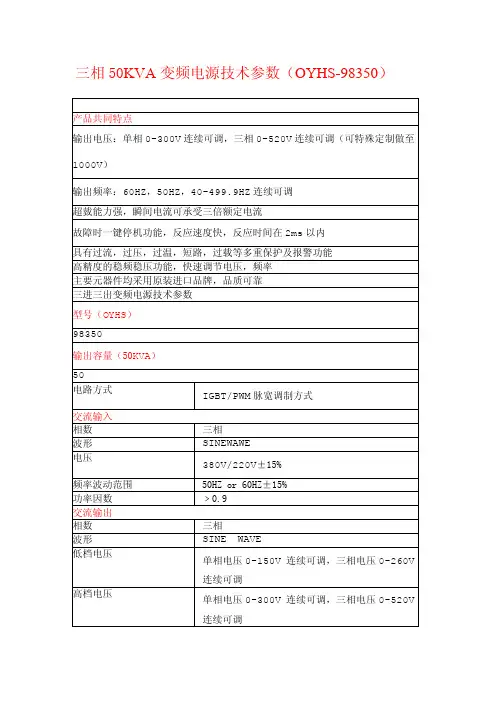
三相50KVA变频电源技术参数(OYHS-98350)产品共同特点输出电压:单相0-300V连续可调,三相0-520V连续可调(可特殊定制做至1000V)输出频率:60HZ,50HZ,40-499.9HZ连续可调超臷能力强,瞬间电流可承受三倍额定电流故障时一键停机功能,反应速度快,反应时间在2ms以内具有过流,过压,过温,短路,过载等多重保护及报警功能高精度的稳频稳压功能,快速调节电压,频率主要元器件均采用原装进口品牌,品质可靠三进三出变频电源技术参数型号(OYHS)98350输出容量(50KVA)50电路方式IGBT/PWM脉宽调制方式交流输入相数三相波形SINEWAWE电压380V/220V±15%频率波动范围50HZ or60HZ±15%功率因数﹥0.9交流输出相数三相波形SINE WAVE低档电压单相电压0-150V连续可调,三相电压0-260V连续可调高档电压单相电压0-300V连续可调,三相电压0-520V连续可调频率60HZ,50HZ,40-499.9HZ连续可调频率稳定率≤0.01%低档最大电流(A)138.9A(0-260V)高档最大电流(A)69.5A(0-520V)整机性能电源稳压率﹤1%负载稳压率﹤1%波形失真度﹤1%效率﹥90%反应时间≤2ms波峰因子3:1保护装置具有过压,过流,超载,输入欠压,过高温,短路等多重保护显示显示介面数位式LED显示电压4位数,数位电压表,解析度0.1V电流4位数,数位电流表,解析度0.1A功率4位数,数位瓦特表频率4位数,数位频率表环境及其它冷却装置高速变频风扇冷却,强制冷风工作温度-10℃to50℃相对湿度0~90%(非凝结状态)海拔高度≤1500m重量(KG)600尺寸(H*D*W)mm1310*800*600注:1以上尺寸不含脚输高度2可根据顾客要求规格特别定制3本公司产品规格不断研发改进,规格若有变更,恕不另行通知。
三相四线制英文表达Three-phase Four-wire System: English ExpressionIntroduction:The three-phase four-wire system is a commonly used electrical power distribution system. It is characterized by three active conductors and one neutral conductor. In this article, we will explore the English expression related to the three-phase four-wire system, including its components and key concepts.1. Voltage and Current:In the three-phase four-wire system, the voltage is typically referred to as line-to-line voltage (VLL) or phase voltage, while the current is denoted as line current (IL). The line-to-neutral voltage (VL-N) can also be calculated. These parameters play crucial roles in determining the power consumption and distribution within the system.2. Phases and Neutrals:The three-phase four-wire system consists of three phases: phase A, phase B, and phase C. These phases carry the main electrical load, and their combination provides a balanced flow of power. The neutral conductor acts as the reference point and completes the circuit by connecting all the currents returning from the loads.3. Power Distribution:Power distribution in the three-phase four-wire system can be represented by the power triangle. The power triangle illustrates therelationship between active power (P), reactive power (Q), and apparent power (S). The power factor (PF) is another important concept, indicating the efficiency of power utilization within the system.4. Load Connections:Various load connections are possible in the three-phase four-wire system. The most common configurations include star (Y) and delta (Δ) connections. In a star connection, the loads are connected between each phase and the neutral conductor. In a delta connection, each load is connected directly between two phases. These configurations offer flexibility in distributing power to different types of loads.5. Advantages and Applications:The three-phase four-wire system has several advantages over other power distribution systems. It offers a higher power transfer capacity, improved efficiency, and balanced load distribution. Consequently, it is widely used in industrial applications, commercial buildings, and large-scale electrical networks.Conclusion:The three-phase four-wire system is a fundamental aspect of electrical power distribution. It provides a reliable and efficient means of delivering electricity for various applications. Understanding the key components and concepts associated with this system is essential for professionals in the field of electrical engineering. Mastering the English expression related to the three-phase four-wire system will further enhance communication and collaboration within the industry.(Note: The word count may vary slightly based on formatting and expansion of certain sections)。
变频技术1.1变频技术的普及前景电机交流变频调速技术是当今节电、改善工艺流程以提高产品质量和改善环境、推动技术进步的一种主要手段。
变频调速以其优异的调速和起制动性能,高效率、高功率因数和节电效果,广泛的适用范圉及其它许多优点而被国内外公认为最有发展前途的调速方式。
电气传动控制系统通常山电动机、控制装置和信息装置3 部分组成,电气传动关系到合理地使用电动机以节约电能和控制机械的运转状态, 实现电能■机械能的转换,达到优质、高产、低耗口的。
电气传动分成不调速和调速两大类,调速乂分交流调速和直流调速两种方式。
不调速电动机直接山电网供电,但随着电力电子技术的发展这类原本不调速的机械越来越多地改用调速传动以节约电能(节约15%^20%或更多),改善产品质量,提高产量。
在我国60% 的发电量是通过电动机消耗的,因此调速传动是一个重要行业,已经得到国家重视,目前已有一定规模。
近年来交流调速中最活跃、发展最快的就是变频调速技术,变频调速是交流调速的基础和主干内容。
上个世纪变压器的出现使改变电压变得很容易,从而造就了一个庞大的电力行业。
长期以来,交流电的频率一直是固定的,变频调速技术的出现使频率变为可以充分利用的资源。
这10年来,变频技术的应用在我国有很大的发展,并取得了良好的效果可以说,变频技术已为大多数用户所接受,但是不能不指出,我国在变频技术的应用方面,与发达国家的水平尚有很大差距,LI前,我国在用的交流电动机使用变频调速运行的仅6%左右,而下业发达国家已达(60%^70%),日本在风机、水泵上变频调速的采用率已达10%,而我国还不足0.01%.在日本,空调器的70%采用了变频调速,而我国才刚刚起步。
从这个现实出发,变频技术尚有很大的发展空间,应该锲而不舍地做好推广应用工作。
且随着控制技术和控制手段的不断提高,变频调速乂山变压变频控制的变频调速发而展到了矢量控制变频调速,通过控制交流电动机里相当于并励直流电动机励磁绕组的磁通变化,提高变频器的恒转矩输出范围和动静态特性,使得交流电动机变频调速系统的性能超过了直流电动机调压调速系统的性能。
The three-phase induction motor speed control methodThree-phase asynchronous motor speed formula: N = 60f / p (1-s) Can be seen from the above formula, change the power supply frequency f, motor pole number p and the slip s may be too much to change the speed of purpose. From the speed of the essence of view, is simply a different way to change speed synchronous AC motor does not change the sync transfer speed or two.Widespread use in production machines without changing the synchronous speed of motor speed control method Wound Rotor Series Resistance Speed, chopper speed control, cascade control, and application of electromagnetic slip clutch, fluid couplings, clutches and other film speed. Change the synchronous speed of change on the number of stator pole multi-speed motor to change the stator voltage and frequency to frequency conversion with no change to the motor speed and so on.Energy from the speed point of view when, with high speed method and inefficient methods of two kinds of speed: high speed when the slip refers to the same, so no slip losses, such as multi-speed motors, Slip frequency control and loss can speed recovery methods (such as cascade control, etc.). A deteriorating loss of speed control methods are inefficient speed, such as series resistance of the rotor speed method, the energy loss in the rotor circuit on; Electromagnetic Clutch The speed method, the energy loss in the clutch coils; fluid coupling speed, energy loss in the fluid coupling of the oil. General deterioration in loss increased with the expansion speed range, if not speed range, the energy loss is minimal.1, variable speed control method of pole pairsThis speed is then used to change the stator winding way to change the red cage motor stator pole pairs to achieve speed control purposes, the followingfeaturesWith hard mechanical properties, good stability;No slip loss, high efficiency; Wiring simple, easy to control, low price;A level speed, differential large, can not get smooth speed control;With pressure and speed adjustment, with the use of electromagnetic slip clutch,smooth and efficient access to high speed characteristics.This method is suitable for the production does not require variable speed machinery, such as metal cutting machine Bed , Lift , Lifting equipment, Fans Water Pump And so on.2, Frequency Control Method Frequency control is to change the motor stator Power supply Frequency, thus changing the speed of its synchronous speed method. Frequency control system main equipment is to provide variable frequency power supply Inverter , Inverter can be divided into AC - DC - AC inverter and AC - AC converter two categories, most of the current domestic use of AC - DC - AC inverter. Its characteristicsHighefficiency, speed the process without additional loss;Wide range of applications, can be used for cage induction motor;Speed range, features a hard, high accuracy;Technical complexity, high cost, difficult maintenance and overhaul.This method is suitable for the high accuracy, good speed performance occasions.3, cascade control method Cascade control is wound into the rotor circuit in the series of additional potential can be adjusted to change the motor's slip, to achieve speed control purposes. Most of the deterioration in power to be in series with the added potential absorbed, re-use generate additional devices to absorb the deterioration in power to return power to use or conversion of energy. Slip-power absorption under way, cascade control can be divided into Motor Cascade control, mechanical and thyristor cascade control cascade control, and multi-use cascade control thyristor, characterized byCan speed the process of deterioration in loss of feedback to the network or productionmachinery, more efficient;Installed capacity and speed range in direct proportion to investment, applicable speed range 70% -90% rated speed of production machinery;peed device failure can switch to full speed, to avoid the cut-off;Thyristor cascade speed low power factor, harmonics greater impact.This method is suitable for fans, pumps and rolling mills, mine hoist, extrusion machines.4, wound rotor motor speed control method of Series ResistanceWound Rotor Motor additional resistance in series, so that the motor slip up, motor running at low speed. The greater the resistance in series, the motor speed is lower. This method is simple, easy to control, but deteriorate the power consumption in the form of heat in the resistor. Is a class speed, soft mechanical properties.5, the stator pressure and speed adjustment methodStator voltage when changing the motor, you can get a different set of mechanical properties of curves, which were different speeds. Since the motor torque and voltage proportional to the square, the largest decline in a lot of torque, speed range of its small cage motors in general and difficult to apply. In order to expand the speed range, pressure and speed adjustment should be larger rotor resistance value cage motors, such as dedicated voltage regulator with speed torque motor, or series wound motor frequency sensitive resistors. In order to expand the range of stable operation, when the speed of 2:1 or more occasions in the feedback control should be adopted to achieve the purpose of automatic adjustment of speed.Pressure and speed adjustment is a key device to provide power supply voltage, the current way of a tandem common saturation voltage regulator Reactor , Auto Transformer And several other Thyristor Surge. Thyristor Surge is the best way. Adjusting Speed featuresPressure and speed adjustment circuit is simple, easy to realize automatic control;Poor power surge process to heat transfer in the rotor resistance in the form of consumption, low efficiency.Pressure and speed adjustment generally applies to 100KW below production machinery.6.electromagnetic speed regulating motor speed control method of electromagneticspeed regulating electric motor squirrel cage motor, electric slip clutch and DC excitation power supply (Controller) consists of three parts. DC excitation power small, usually consisting of single phase half-wave or full wave rectifiers thyristors composition, change thyristor conduction angle, you can change the magnetizing current size.Electromagnetic slip clutch armature, poles and excitation windings composed of three parts. Armature and the latter has no mechanical contact, are free to rotate. Armature motor coaxial connection active part, driven by motors; docking with the load axis magnetic pole coupling from the moving parts. When the armature poles are at rest, such as excitation windings for DC, along the circumferential surface will form a number of air gap on the n, s, of alternating polarity poles, the magnetic flux through the armature. Dang electric armature with drag motor rotating Shi, due to electric armature and pole between relative movement, and makes electric armature induction produced Eddy, this Eddy and magnetic pass mutual role produced go moments, led has pole of rotor by same direction rotating, but its speed constant below electric armature of speed N1, this is a go difference adjustable speed way, changes go difference clutch device of DC Lai magnetic current, will can change clutch device of output go moments and speed. Characteristics of electromagnetic speed regulating motor speed:appliances, structure and control circuit is simple, reliable operation, easymaintenance; speed and smooth, stepless speed regulationthe power network harmonic effects;lost speed, low efficiency.This method applies to medium and small power, requires low speed when the smooth, short run production machinery.7. the hydraulic coupler speed regulating hydraulic Coupler is a device for hydraulic drive, is made up of the pump and turbine, they collectively work wheels, placed in a sealed case. Shell filled with a certain amount of working fluid, when pump is impulse driven by rotation, in which liquid propelled by blades which rotate, and under the action of centrifugal force along the outer wheels when entering the turbine pump, to thrust to the turbine blades on the same turn, make it drive production machinery running. Power transfer capacity of the hydraulic coupler and shell filled with fluid volume sizes are consistent. In the course of work, changing the filling rate can change the coupler of turbine speed, stepless speed regulation, characterized by:power scope, can meet the needs of from a couple of different power 10-kilowattto shuqianqian;simple structure, reliable performance, easy to operation and maintenance, andlow cost;small size, capacity;easy to adjust, easy to fulfill automatic control.This method applies to the speed of the fan and water pump.三相异步电动机的几种调速方式三相异步电动机转速公式为:n=60f/p(1-s)从上式可见,改变供电频率f、电动机的极对数p及转差率s均可太到改变转速的目的。
![[英语学习]钢铁冶金中英文词汇──三电部分-精品文档](https://uimg.taocdn.com/afc385f0195f312b3069a503.webp)
1吨磅秤称量箱 box for weight of 1-ton scale PNPN型开关二极管 PNPN diodePN结激光器 PN junction laserR信号(已收到) signal R ( received)T形线夹 T-shaped wire clipU形插塞 U-linkU形磁铁 horseshoe magnetU形管压力计 U-tube manometerV形接法 V-connection;open delta connectionV形拉线 V-stayguyY-∆接法 Y-delta connectionY-∆形起动器 star-delta starter; Y-delta starterY形结线 Y-connection; star connectionY形拉线 Y-stay艾多福投影机 Eidophor projector安培 ampere安培容量 ampere capacity安培小时 ampere-hour (Ah)安全灯头插口 bayonet safety lamp socket安全开关 safety cut-out; safety switch;safety cut-off安全日光灯座 safety fluorescent lamp socket 安全遥控设备safety remote control equipment 安全载流量 safe carrying capacity安装图installation diagram; installation drawing; erection drawing; erecting drawing 安装误差 erection error按 press; push按钮 button按钮电话 push-button telephone按钮开关push-button; phshbutton; push button; press-button; key button; button按钮控制器 press button control; push-button control暗敷设concealed wiring; laid concealed; concealed laying暗红 dark red暗配线 concealed wiring暗室 dark room暗装的 concealed凹度 concavation白炽灯 incandescent lamp; incandescence lamp; incandescent light; filament lamp; tungsten filament lamp百分数误差 percentage error百分之…………per cent; ……percent; ……% 百叶窗 louver; shutter半闭式循环 semi-closed cycle半波整流器 half-wave rectifier; single-way rectifier半导体二极管 semiconductor diode半导体管电路 transistor circuit半导体激光器 semiconductor laser半导体开关元件 thyristor半封闭式电动机 semi-enclosed type motor; semi-enclosed motor半封闭式开关装置 semi-enclosed switchgear 半负载 half-load半圆球罩 semi-globe lamp shade半圆形灯 dome lamp饱和电抗器saturable reactor; saturation reactor; transductor保安电阻 protective resistance; protective resistor保护断路器 protective circuit breaker保护继电器protective relay; protection relay; protect relay保护接地系统 protection earthing system保护套管 protective sleeve保密码 secret code保险丝 fuse保险丝盒 fuse box报警灯 alarm lamp; guard lamp; warning lamp 报警灯 danger light报警电路 alarm circuit; warning circuit报警继电器 alarm relay; alarming relay报警系统 warning system报警信号 guard signal; alarm signal; warning signal报警装置 alarm device报警装置 alarm device报时信号 time signal爆炸 explosion爆炸危险 explosion hazard备件spare parts; spares; reserve parts; repair part;service parts备用 emergency备用电池 emergency battery; emergency cell; stand-by battery备用电源stand-by power supply; stand-by power source; reserve power supply; emergency power supply备用机组 standby unit, emergency set备用接点 spare contact, standby contact备用容量 reserve capacity; margincapacity; idle capacity背板 backboard背面接线图 back connection diagram被保护设备 equipment being protected被测压力 measured pressure被控系统 controlled system被控制量controlled variable, regulated variable本地广播信道 local channel比例尺 scale比例系数 proportional coefficient闭合 make; closing; closure; close-up闭合电路 close circuit; closed loop闭环控制 closed-loop control闭路电视 closed-circuit television (CCTV)闭式循环 closed cycle闭锁继电器 block relay壁灯 bracket lamp; bracket light; wall lamp 壁挂式 bracket type避雷带 strap type lightning protector避雷器arrester; lightning arrester; lightning protector; surge discharger; spark-gap避雷器开关 arrester switch避雷网 network of lightning conductor避雷针lightning rod; air terminal; lightning conductor; lightning guard编号 code number; serial number; numbering 编码矩阵 encoding matrix编码器 encoder编织电缆 braided cable编织线 braided wire; litz line扁孔插座 receptacle for flat pin扁形电缆 flat cable; ribbon cable; tape cable 变电所 transformer station, substation变电所 substation; transformer substation; transforming station; transformer station变电站 substation; transformer station; transformer substation; transforming station 变电站变压器 substation transformer变化 variation; change变换器converter; convertor; changer; inverter; transverter; transformer变量 variable; variable quantity变流器changer; converter; convertor; transverter变码 garbled code变频器frequency changer; frequency converter; converter; convertor; transverter 变频同步发电机 variable frequency synchro generator变送器 transducer; transmitter变压 voltage transformer变压比transformer ratio; transformation ratio; turns ratio; ratio变压器 transformer变压器低压侧 low voltage side of transformer; step-down side of transformer变压器高压侧 high tension side of transformer; high-voltage side of transformer; step-up side of transformer变压器利用系数transformer utilization factor变压器容量 transformer capacity变压器室 transformer room; transformer vault; transformer compartment变压器损耗 transformer loss变压器铁心 transformer core变压器亭(配电亭) kiosk变压器线圈 transformer coil变压器箱 transformer tank变阻器 rheostat; varistor变阻式调压器 rheostatic voltage regulator标称电路电压 nominal circuit voltage标称电压 nominal voltage; rated voltage标称容量 nominal capacity标记 mark; marking; sign标签 label; tag 标准件 standard parts标准配件 standard fittings标准设备 standard equipment标准设计 standard design标准图 standard drawing; typical drawing标准图目录 list of standard drawing表 table; list; schedule; sheet; meter; gauge 表盖 meter cover表壳 meter case表面高温计 surface pyrometer表面面积 surface area表面式冷凝器 surface condenser表面温度计 surface thermometer表面泄漏电流 surface leakage current并激电动机 shunt motor并联电路 parallel circuit; shunt circuit并联电容器 shunting condenser并联电阻resistance in parallel; parallel resistance; shunt resistance并联绕组 parallel winding并联稳压器 shunt regulator并联阻抗 shunt impedance并列负载 shunt load拨号盘 dial波门录取 gate extraction波绕组 wave winding玻璃纤维 glass fiber; fiber glass; glasswool 播音室 studio播音室广播 studio broadcast播音室广播节目 studio program播音员 announcer铂铂铑热电偶 Pt-Pt-Rh thermocouple铂电阻温度计 platinum resistance thermometer 铂合金 platinum alloy铂热阻 platinum thermistor薄壁穿线钢管 thin wall steel conduit薄膜电线管 light-wall conduit薄片 lamina; lamel; lamella补偿电动机 composted motor补偿电缆 cable for compensation补偿电路 compensation circuit补偿电容器compensating capacitor; compensation condenser; compensating condenser补偿电阻器compensating resistor; compensation resistor补偿过度 over-compensation补偿器 compensator; compensation apparatus 补充 supplement; making-up补救 remedy不便移动式用电设备 stationary appliance不带电的金属外壳non-current carrying metallic case不等速的 non-uniform velocity不定期检查 casual inspection不对称的 asymmetric; dissymmetric; unstmmetrical; non-symmetrical不发火 nonsparking不方便 inconvenience不合格 unguarded不合理的 unreasonable不合适 misfit不间断的操作 non-stop operation; continuous operation不接地中性点 insulated neutral point不可靠性 unreliability不连续性 discontinuity不良导体 poor conductor不良接点 bad contact; imperfect contact不平衡馈电线 unbalance feeder line不平衡三相电路unbalanced three-phase circuit不平衡三相电压unbalanced three-phase voltage不平衡三相负载 unbalance three-phase load不切断切换触点 holding transferring contact 不燃的 non-inflammable; non-combustible不同部门电缆并列parallel arrangement of different purpose cables不透明 opacity不透气的 air-tight; gas-tight不透水的 water-tight不用稿子的广播 unscripted broadcast不圆度 out of roundness不正常电压 abnormal voltage布暗线 concealed wiring布电线 electric wire ( cotton covered )布明线 open wiring; exposed wiring布线电容 wiring capacitance; wiring capacity 步 step步进开关 stepping switch; step switch步进旋转选择器 step-by-step type uniselector 步谈机 walkie-talkie部门 department材料单 bill of material彩色传输 color transmission彩色电视 color TV彩色信号 TV signal参比电压 reference voltage参比频率 reference frequency参比条件 reference condition参比温度 reference temperature参考线 reference line操纵operation; operating; control; manipulation;manoeuver; maneuver操纵按钮 control button操纵板 control pane; control desk操纵设备 control unit; commanding apparatus 操纵室 control chamber; control room操纵台control desk; control console; control panel; control board; operation's desk; bench board操纵系统 control system操作程序 sequence of operations操作工序operational sequence; operation sequence操作平台 operating platform 操作人员operator; operating personnel; operating staff操作失误 misoperation操作误差 operate miss操作须知 operating instruction操作员终端 operator terminal槽式充油油开关 oil bath type oil circuit braker草图sketch; sketch drawing; draft; rough draft; rough drawing侧灯 side lamp; side light测力计 dynamometer测试 test测试设备instrumentation; testing device; test equipment测试用变压器 testing transformer测试用放大器 test amplifier叉形拉线 forked stayguy插接式母线槽 plug-in bus duct插孔板 female receptacle插口灯座 bayonet lamp socket; bayonet holder; bayonet base; bayonet socket插口平灯座 bayonet flush lamp socket插入 inserting; inset in; inlay; plug in插入式 plug-in type; jack-in type插入式保险丝 plug fuse; push-in fuse插入式继电器 plug-in relay插入式熔断器 plug fuse插塞开关 plug switch插塞式保险丝 plug cut-out插塞式熔丝 plug fuse插头 plug; plug pin插头(塞子) plug插头风扇 oscillating fan插座 receptacle; socket; outlet;female receptacle; plug receptacle插座(塞孔) jack, socket查号台 directory enquiry差 difference差动测量 differential measurement差动电流计 differential galvanometer差动式压力表 pressure manometer差动仪表 differential instrument差压式传感器 differential pressure pick-up 拆除 dismantle拆下 detach拆线 cutting the line拆线键 clearing button柴油发电机 diesel dynamo; diesel generator 长波 long wave长方形孔 slot长期过载 prolonged overload长途电话 long distance telephone calls, trunk call, (Am.) long distance call长途电话台 long-distance exchange( operator )常闭触点 normally-closed contact; normally closed contact; normally-made contact常开触点normally open contact;normally-open contact; normally-broken contact; normally opened contact厂区照明illumination of factory site; lighting of plant site厂用电系统 station service system敞开式 open type敞开式保险丝 open fuse敞开式熔断器 open type fuse超短波 ultra short wave超高频 ultra frequency超高压super-voltage; super-tension; super-high tension; super-high voltage超高压电网 supergrid超高压水银灯 super-high voltage mercury lamp 超功率继电器 over-power relay超前电流 leading current超前角 angle of advance; angle of lead; lead angle;advance angle超声波 ultrasonic wave超声波探伤仪 ultrasonic flaw detector超声波探伤仪 ultrasonic flaw detector超正析摄像管 image orthicon超重型 extra-heavy-duty潮湿环境 damp location; location moist潮汐电站 tidal power station车间 shop; workshop; plant; department衬里 liner; lining称重传感器 weight transducer(sensor)撑木 brace成反比的 inversely proportional成套备件 set of spare parts程序 program程序 program; programme; procedure; sequence 程序控制 program control程序控制触点 sequence-controlled contact程序设计系统 programming system持续短路 sustained short-current持续短路电流 steady short-circuit current; sustained short-circuit current持续时间 duration尺寸公差 dimensional tolerance充电电缆 charging cable充电电流 charging current充电电容器charging capacitor; charging condenser充电电压 charging voltage充电电阻 charging resistance充电电阻器 charging resistor充电二极管 charging diode充电指示器 charging indicator充气电缆 gas-filled cable; gas cable充气电容器 gas-filled capacitor充气式温度计 gas-filled thermometer冲击电流 impulse current冲击电压 impulse voltage冲击电压试验 impulse voltage test冲击负载 impulse load; shock load冲击型水轮机 impulse water turbine 冲孔 punch虫胶 lac; shellac虫胶清漆 shellac varnish抽水蓄能式水电站 pump-storage power station 抽头 tap; tapping抽头变压器 tap transformer抽头转换开关 tap changer出厂长度 completed length出线容量 outlet capacity初步加工 pre-treat初步设计 preliminary design; basic design; predesign; outline design初级(一次)屏蔽 primary shield初速 initial velocity除气器 de-aerator储备系数 assurance factor触点 contact触电 electric shock; elelctroshock触电危险 shock hazard触发电路 trigger circuit触发器 trigger; flip-flop触摸式键盘 touch key board触头 contact穿墙进线绝缘导管 wall entrance insulator穿墙套管wall bushing; wall entrance bushing sleeve穿心式绝缘子 shackle insulator穿越套管 thoroughfare bushing传动 drive传感器 sensor, sensing element传呼电话 messenger call传呼电话 messenger call串并联 series parallel串联 series connection串联电路 series circuit; current circuit串联电容 series capacity串联电容器设备 series capacity installation 串联电阻series resistance; resistance in series串联电阻器 series resistor串联扼流圈 series reactor串联过载继电器 series over-current relay串联式相位补偿器 series type phase advancer 串联线圈 series coil垂直度 verticality垂直分量 vertical component垂直天线 vertical antenna瓷大螺口管子灯头 porcelain big screw tube lamp socket瓷管型油断路器 porcelain type oil circuit breaker瓷绝缘子 porcelain insulator瓷绝缘子 porcelain insulator瓷瓶 porcelain insulator瓷质灯头 porcelain knob磁吹避雷器 magnetic blow-out arrester磁带 magnetic tape磁带机 tape handling unit磁带录像 video tape recording( VTR )磁带录音机 tape recorder磁轭 magnetic yoke磁放大器 magnetic amplifier磁化电流 magnetizing current磁化线圈 magnetizing coil磁开关 magnetic switch磁控管 magnetron磁控制器 magnetic controller磁力开关 magnetic switch磁力探伤仪 magnetic flaw detector磁力脱扣器 magnetic trip磁盘 magnetic disk磁盘录像 magnetic disc recording磁探伤法 magnetic fault find method磁探伤仪 magnetic flaw detector磁铁 magnet磁铁制动器 magnetic brake磁通密度 flux density; magnetic flux density 磁性元件 magnetic element次分支 sub-branch次级(二次)屏蔽 secondary shield粗调 coarse regulation; coarse adjustment; rough adjustment粗加工 pre-treat粗线 thick line; heavy line错缝 dislocation错开 stagger错算 miscount错误 E (error)搭接 lap; overlap joint搭接焊 lap welding答问比赛节目 quiz program打错了。

Photovoltaic Power Pupply Pine Pave Inverter Based On68HC908MR16 MCU1 IntroductionWith the growing energy crisis and increase the environmental awareness of mankind,the development and utilization of new energy is reccining increasing attention. And solar energy as an inexhaustible supply of highly efficient non-polluting energy has more people of all ages. In this paper, the photovoltaic power system is sinusoidal inverter suitable for a household, especially for electricty without electricity in remote areas of the western region of a power systm users, as China’s western development will be its market prospects will become more and more broad.2 Structure and principle of the inverter system2.1 The basic structure of the systemFirst of all, by the solar array to the battery charging circuit in order to get a basic stability of the DC voltage, and then by the inverter ciruit will be high-frequency alternationg current into direct current recerse, and finally by the frequency step-up transformer and filter circuit filtering into 50Hz,220V sinusoidal AC voltage.Control of the whole system is completed by a single-chip MR16.The core part of the formation of SPWM wave and the output AC voltage according to the feedback form, composed of sampling digital PI regulator part.2.2Single-chip on the MR1668HC908MR 16 single chip is a low-cost, high-performance single-chip 8. It has 32k bytes of rewritable flash memory-chip FLASH,with 768 bytes of RAM,this system completely enough;with a dedicated motor for 6-channel PWM output PWMMC modules, suitable for in single-phase, three-phase inverter, at the same time the module was also devoted to the protection Fsult FAULT pin 4, whem the fault does not occur in the case of interruption caused by the rapid blockade of the PWM output to achieve the purpose of protection; with the option external crystal clock or internal clock phase-locked loop clock generator modul, the system chosen by the internal PLL clock can producc accurate 8MHz internal bus frequency, so as to ensure the accuracy of the frequency of the system; with programmable AD clock. AD fastest conversion time only 2μs,to minimize disroption of program execution tim;with SCI serial communication interface, can work infull-duplex or half-duplex mode, in this system can reliably be completed with the outside world keyboard monitor serial communication system.2.3 Inverter Main CircuitSwitching device is appropriate for low-power devices, with switching speed, high frequency characteristics of the power MOSFET. Switch gate drive signal from the single-chip MR16 wave generated by the SPWM signal driver circuitl Full-bridge inverter SPWM output for high-frequency wave, the step-up transformer and filter immediately be 220V,50Hz standard AC ovltage sinusoidal.2.4 SPWM wave formation68HC908MR16 with a special single-chip motor control can be used to work in threepairs of complementary mode or standalone mode, including 6-channel PWM output module PWMMC, Initialization of the system in its work in three pairs of complementary patterns in the same bridge that the two PWM signal arm is complementary, in the initialization of dollars to write a value to the PMOD(H:L) in orde to determine the carrier frequency that is switching frequency. Real-time wave PWM pulse width calculation is completed by the interruption of the procedure, each PWMMC module PCTN(H:L) register, single-chip will PV ALX(H:L) of the value of PMOD(H:L) after the value in the automatic generation of SPWM signal sent by the PWM pin,. In order to prevent the same bridge arm of the two tubes at the same tine the phenomenon of conduction occurred in the absence of signal generator DEADTIME in DEADTM writes a register balue to determine the dead time. The design of the system time for 2.5μs, the carrier frequency to 10KHz, including 200 made to enlarge the value of the sine sine table. There are 4modules PWMMC fault protection port FAULT1~FAULT4,when the port when high, PWMMC initialization can be set to block in accordance with the corresponding PWM output, the sstem is the use of the over-current protection function, When over0current, it FAULT1 home port in order to place all six road blockade PWM port. PWMMC work the system so that the center alignment mode, in the PWM clock frequency of 8MHz carrier under its formula for the cycleCarrier cycle =1/10k=PMOD(H:L)×(1/8M)×2Therefore, the system must be initialized PMOD(H:L) =$0190(Note: $for the MR16 in hexadecimal notation)2.5 System control structureThe system through the digital PI regulator to control realization of regulators. The control system block diagram shown in figure 3.AC voltage feedback signal from the AD sample. In order to ensure accuracy, the system uses sampling voltage transformer,Just start to set output voltage from the soft-start, soft-start is generated at startup in order to avoid large peak currentl. Soft-start the use of successive incremental increases to a voltage required for the method,after the soft-start voltage is set to correspond to 220V voltage values, In order to enhance the speed, the system uses a feedforward control and feedback control of the control method of combining.In order to enhance the output characteristics of the dynamic system. The system changes in accordance with the ratio of deviation of the size of coefficient and integral coefficient of the fuzzy control method, when the deviation is larger, the proportion coefficient and integral coefficient is aslo larger., when the deviation of the proportion of small coefficients and imtergral coefficient smaller, thus reducing the overshoot, it iseasy to make the system stable,the total elimination of the integral saturation phenomenon,but also to enhance the adaptability of the system.3 Serial CommunicationIn order to enhance the system's ability to adapt to different environments,it is necessary to monitor and control system to monitor and modify the parameters of regulation,this system uses a serial communication technology keyboard monitoring system with the outside world to communicate.Procedures on the use of inquiry methods to the outside world periodically send test data,test data including the solar cell voltage,charge current, battery voltage,DC current ,output voltage,output current, heat sink temperature,when the event of the failure priority send faultsignal,when the need to modify parameters and modify data on the reception of the corresponding parameters,and use the methods of calibration and calibration test of the accuracy of data communication. MAXIM's hardware as a MAX485 interface chip to work in half-duplex mode, while the system optocoupler isolation systems approach to enhance anti-interference ability and reliability.4 System software designThe modular design of system software, including the initialization module, the protection module, regulator modules, communication modules, such as interruption of program modules,in addition to disruption of modules outside the main program on the remaining modules, which will completion of system initialization main module initialization, the variable unit, given the initial value of the register unit.Protection module in accordance with voltage and current sample values to determine fault and the fault occurs in the PWM output of the blockade. Protection,including under-voltage battery voltage, over-voltage protection can be achieved since the restoration, that is, the battery voltage is detected and returned to normal, the system re-soft start and resume normal work. Overcurrent protection as a result of the rapid response they need to protect the use of hardware, when the over-current at the time of the blockade as soon as all the PWM output, but also sealed off all the driving circuit, only to return to work can be rest, software can determine whether there has been over-current protection.Regulator module to complete the system of the PI regulator output voltage regulation, entrance to the output parameters for the soft-start exports to the disruption module M parameters involved in the calculation of PWM pulse width. Through real-time adjustment of the value of the parameter value can be changed so that the output pulse width given to follow.Interruption of program modules to complete the issue of SPWM waveform, AC voltage, AC current parameters of the sample. Interruption of the entrance parameters of PI regulator for the output parameter M, the parameters involved in the calculation of pulse width that is PV ALX(H:L) values calculated, thus changing the duty cycle which regulates the output voltage 2 in accordance with the the rules of SPWM sampling methods, combined with the initialization of PWMMC set formula for calculating real-time pulse width for real-time pulse width forIs a half cycle:PV ALX(H:L)=PMOD(H:L)/2+M*SIN(PTR)Negative half-cycle:PV ALX(H:L)=PMOD(H:L)/2-M*SIN(PTR)One PTR pointer to sine table, SIN (PTR) for the corresponding sine value of the pointer PTR.5 ConclusionPrototype made in accordance with the above thinking, the last to be relatively standard 220V,50Hz sinusoidal voltage, soft-start is also very stable, its frequency error <=0.1%,the output voltage err of <=0.5%. As a result of the carrier frequency of 10KHz, in the transformer primary side to be 20kHz high-frequency signals without noise. Under the above-mentioned control can ensure the system load or a sudden reduction in load to maintain output voltage stability quickly. Keyboard and monitor system with the outside world of the scrial. Communication good,strong practicality and reliability.基于68HC908MR16单片机的光伏正弦波逆变电源1 引言随着能源危机的日益加剧和人类环保意识的提高,新能源的开发利用越来越受到人们的重视。
Frequency conversion power(变频电源)Frequency conversion power is the AC utility by AC and DC and AC conversion for pure sine wave, output, the output voltage and frequency adjustableinside certain limits. It is used in different frequency conversion motor speed controller, different from the gen eral ac voltage stabilizer. The ideal ac power is characteristic of frequency stability, voltag e stability and resistance equal to zero,the voltagewave form distortion for pure sine wa ve.Frequency conversion power is close to ideal ac power, therefore, advanced developed c ountries are increasingly will inverter power supply power, so as to provide the most exce llent with electric power supply environment, facilitate objective appraisal appliances techni cal performance.Frequency conversion power mainly largest categories: linear put largeand SPWM switch.Structurally, frequency converter can be divided into direct and indirect frequency. Dir ectly into a frequency converter and said, it is a kind of frequency alternating current to direct the ac frequency conversion control, for no dc link between the frequency conversio n and indirect form: a has been called into frequency inverter, will be passed through rect ifier ac to dc rectification, again through the inverter frequency converting dc frequency fo rm of variable frequency, therefore thisway is called again have dc link frequency.A general use into inverter switch device is thyristor using automatic voltage is zero and become negative features, thyristor directly on the ac power, thyristor cannaturally shu toff. The process and controlled rectifier, no need for additional element method is simple, reliable operation. But, in a low frequency output waveformin nearly sinusoidal, and for a variable flow, high efficiency, also can achievequadrant operation. But because of this met hod using thyristor amount is more complex, the main circuit, and the output power frequ ency limit by frequency, generally not higher than 1/2 of the grid frequency, so pay a ac indution motor speed inverter in aspects of low power transmission, mainly used for high starting torque,especially the occasion.Pay a converter is currently has been the main form of variable frequency power,this way must through the AC/DC and AC/DC power transformation twice. Efficiency is lower. But the former level does not affect the mains interference, the output waveform after cl ass, wide frequency. The AC/DC converter is always ainto the current inverter power to f orm, the soil must be through the AC/DC and AC/DC power transformation twice. Effi ciency is lower. But the former level does not affect the mains interference, the output wa veform after class, wide frequency.AC/DCAlternating current to direct current, namely to AC/DC transformation. This function transform circuit commonly called rectifier circuit. In the process of transformation of AC/ DC frequency conversion, often introduced to reduce weight and volume of power equipm ent, and improve efficiency, improve the dynamic characteristics,frequency conversion purp oses for decades KHZ to hundreds of KHZ. In the 1970s by frequency 50Hz ac utility p ower to the dc linear manostat development to switch frequency for 20kHz dc switching p ower supply, known as the "revolutionary", but only 20kHz after ten years of switch pow er supply, the frequency conversion to 500kHz above.DC/ACAlternating current, direct current will become namely DC/AC conversion. This function transform circuit, commonly known as the inverter. Inverter circuit can be fixed d c voltage transform for fixed amplitude and frequency of the ac voltage, also will transfor m into its amplitude and frequency adjustable voltage, which often called inverter. Inve rter power electronics device is the important componentof uninterrupted power supply, ele ctricity transmission, and many other equipment m-frequency power of the core, the resear ch work more people's attention, the focus of research is how it is convenient to adjust th e inverter power supply output voltage and frequency, and lower harmonic content, improv ing the output waveform. So far, the lower harmonic content and adjust the output voltage (or frequency) common measures are:1) on the switch tube inverter frequency PWM inverter, make the picture for high frequen cy output as PWM waves.2) by changing the inverter circuit topology structure, in the circuit to reconstruct to wave output waveform, reduce ladder low-order harmonic content.PWM technology is using semiconductor switching device conduction and shut off the dc voltage into voltage pulse, and through the control voltage pulse width to achieve the purpose of variable frequency control technology, a. SPWM sine pulse-width modulation is produced by the control circuit of a group of rectangular pulse width and differ, used to approximate sine sequence voltage wave.For high frequency PWM switch, the higher the frequency, the smaller of harmonic content, but the switch loss is bigger also, unfavorable use in high-power inverter. But oft en require multiple wave reconstruction way to realize the voltage inverter. Waveform reco nstruction, the more the lowest series higher harmonic frequency, but the main circuit and control circuit is more complex, accordingly, the control voltage regulation is not very convenient, so this way in high-power inverter power supply usually only.Using PWM to adjust output voltage and lower harmonic content is currently the mos t popular technologies in small power inverter is widely used, PWM method of generating many.Frequency conversion power adopt PWM technology has two kinds:A preset control mode is switch, also called selective harmonic elimination PWM, theoretical analysis shows that, in 1973, the selective harmonic elimination control strategy can effectively overcome these problems, it only need less switches can be completely eli minate impulse number of large capacity, high order harmonic lowhas achieved very go od filtering effect, switch low frequency and voltage switching loss, utilization rate is high er many advantages, PWM inverter control method of the ideal.Selective harmonic elimination PWM control is a PWM control strategy, the calculation m ethod is: through their basic PWM control Fourier analysis, Fourier series,pulse, for unkno wn displacement of certain harmonic zero, then get a nonlinearequations, the equations for selective harmonic elimination PWM model, according to the results of model, excluding the output control these specific low-order harmonic. The advantages of the selective har monic elimination control for people to recognize and develop a lot of research work, hop e this method of practical application. Unfortunately, so far, selective harmonic elimination method is not really into actual application.According to the ideas, selective harmonic elimination control PWM waves of phase is obtained by solving the model and selective harmonic elimination model is a sine func tion of multivariate nonlinear equations, and its numerical solution of complicated and diff icult process, so that the solution convergence calculation in existing microprocessor (MCU) system in real-time to finish, it is very difficult to a considerable extent restricted in the practical application of selective harmonic elimination method. Now the application of this method to control soil, and its application in the need to adjust the size of the constant fr equency voltage constant-voltage source control is feasible, Certain beforehand calculation or relevant control parameters in the voltage in memory, according to actual needs, the ou tput voltage classification way often requires a lot of storage space, and with the resolutio n of the voltage regulator, with its storage space.Another kind is SPWM scheme, the disadvantages of SPWM is hard to obtain higher amplitude, switch loss is bigger. Through improving the advantage is that it can reduce s witching frequency and low harmonic by adjusting the pulse width to adjust output voltag e. One SPWM inverter mode and divided into three types:(1) controlled rectifier voltage and frequency inverter. V oltage and frequency function in t wo links from control circuit, coordination, simple structure, convenient control. Due to th e input device controlled rectifying, when using link low voltage, large in triggering Angle, low input power factor, besides multi-purpose thyristor inverter type 2 ladder wave commu tation 2 times per week, the inverter, device switch frequency low output harmonic big, of course, controllable devices such as IGBT of PWM control becomes possible, can great ly improve the performance, but the cost is high.(2) Not controlled rectifier voltage rectifying, chopper, inverter frequency modulation mode. Because of using diode rectifier, make the input power factor improvement. Due to the ou tput power link inverter using thyristor, still have the big output harmonic.(3) Is not controlled rectifier rectifier, pulse width modulation (PWM) inverter and realize FM mode voltage. At high power factor in input devices, and adopts high frequency inver ter switch, output and excellent performance. Small harmonicFrequency conversion power application purpose and field:Due to the world, the power indicator export manufacturer needs to supply electric simulation of different countries, for engineers in network design, development, productio n and quality test of product inspection, life, high voltage simulation test applications/provi de pure reliable, low harmonic distortion, high frequency and voltage stability of power ou tput rate of sine wave, Import original electric equipment, users need to China power grid, frequency conversion variable import equipment, Meet avionics and military equipment, th e high demand.Mainly used for manufacturing or export trade business of export products of electric power test, debug and used for precision instrument power supplies. Widely used in home appliance manufacturing, motor, electronics manufacturing, IT industry, computer equipmen t, laboratory, etc.★appliance manufacturers:air conditioning, coffee machine, washing machine, juice extra ctor, microwave oven, tape recorder, refrigerator, DVD, welcome, electric razor etc. Produc t test power.★electronics manufacturers such as: electrical switching power supplies, transformers, elec tronic ballast and AC electric fans, unceasingly, charger, relays, system ofcompressor, moto r and passive components etc. Product test power.★Painted IT industry and computer equipment manufacturers such as: fax, copy machine, shredders, printers, scanners, cd-rw drive, servers, and displays the products such as test power.★Laboratory tests and painted units such as: ac power test and product life andsafety tes ting, emc test and OQC (FQC) test and r&d, product testing and research unit best ac po wer.★aviation/military units such as: the airport facilities, ship, aerospace, military institute of test power. Etc.中文翻译变频电源变频电源是将市电中的交流电经过AC→DC→AC变换, 输出为纯净的正弦波,输出频率和电压一定范围内可调。
英文资料及中文翻译The Design of a Rapid Prototype Platform for ARM BasedEmbedded SystemHardware prototype is a vital step in the embedded system design. In this paper, we discuss our design of a fast prototyping platform for ARM based embedded systems, providing a low-cost solution to meet the request of flexibility and testability in embedded system prototype development. It also encourages concurrent development of different parts of system hardware as well as module reusing.Though the fast prototyping platform is designed for ARM based embedded system, our idea is general and can be applied to embedded system of other types.**Embedded systems are found everywhere, including in cellular telephones, pagers, VCRs, camcorders, thermostats, curbside rental-car check-in devices, automated supermarket stockers, computerized inventory control devices, digital thermometers, telephone answering machines, printers, portable video games, TV set-top boxes -- the list goes on. Demand for embedded system is large, and is growing rapidly.In order to deliver correct-the-first-time products **plex system requirements and time-to-market pressure, design verification is vital in the embedded system design process. A possible choice for verification is to simulate the system being designed. If a high-level model for the system is used, simulation is fast but may not be accurate enough, with a low-level model too much time may be required to achieve the desired level of confidence in the quality of the evaluation. Since debugging of real systems has to take into account the behavior of the target system as well as its environment, runtime information is extremely important. Therefore, static analysis with simulation methods is too slow and not sufficient. And simulation cannot reveal deep issues in real physical system.A hardware prototype is a faithful representation of the final design, guarantying its real-time behavior. And it is also the basic tool to find deep bugs in the hardware. For these reasons, it has become a crucial step in the whole design flow. Traditionally, a prototype is designed similarly to the target system withall the connections fixed on the PCB (printed circuit boards).As embedded systems are getting **plex, the needs for thorough testingbecome increasingly important. Advances in surface-mount packaging and multiple-layer PCB fabrication have resulted in smaller boards and **pact layout, making traditional test methods, e.g., external test probes and "bed-of-nails" test fixtures, harder to implement. As a result, acquiring signals on boards, which is beneficial to hardware testing and software development, becomes infeasible, and tracking bugs in prototype becomes increasingly difficult. Thus the prototype design has to take account of testability. However, simply adding some test points is not enough. If errors on the prototype are detected, such as misconnections of signals, it could be impossible to correct them on the multiple-layer PCB board with all **ponents mounted. All these would lead to another round of prototype fabrication, making development time extend and cost increase.Besides testability, it is important to maintain high flexibility during development of the prototype as design specification changes **mon. **plex systems are often not built from scratch but are assembled by reusing previously designed modules or off-the-**ponents such as processors, memories or peripheral circuitry in order to cope with more aggressive time-to-market constraints. Following the top-down design methodology, lots of effort in the design process is spent on decomposing the customers, requirements into proper functional modules and interfacing them to compose the target system.Some previous research works have suggested that FPLDs (field programmable logic device) could be added to the final design to provide flexibility as FPLDs can offer programmable interconnections among their pins and many more advantages. However, extra devices may increase production cost and power dissipation, weakening the **petition power of the target system. To address these problems, there are also suggestions that FPLDs could be used in hardware prototype as an intermediate approach [1]-[3], whereas this would still bring much additional work to the prototype design. Moreover, modules on the prototype cannot be reused directly. In industry, there have **panies that **mercial solutions based on FPLDs for rapid prototyping [4]. Their products are aimed at SOC (system on a chip)functional verification instead of embedded system design and development.In this paper, we discuss our design of a Rapid Prototyping Platform for ARM based Embedded System, providing a low cost solution to meet the request of flexibility and testability in embedded system prototype development. It also encourages concurrent development of different parts of system hardware as well as module reusing. The rest of the paper is organized as follows. In section 2, we discuss the details of our rapid prototyping platform. Section 3 shows the experimental results, followedby an overall conclusion in section 4.II. THE DESIGN OF A RAPID PROTOTYPING PLATFORMA. OverviewARM based embedded processors are wildly used in embedded systems due to their low-cost, low-power consumption and high performance. An ARM based embedded processor is a highly integrated SOC including an ARM core with a variety of different system peripherals[5]. Many arm based embedded processors, e.g.[6]-[8], adopt a similar architecture as the one shown in Fig.1.The integrated memory controller provides an external memory bus interface supporting various memory chips and various operation modes (synchronous, asynchronous, burst modes). It is also possible to connect bus-extended peripheral chips to the memory bus. The on-chip peripherals may include interrupt controller, OS timer, UART, I2C, PWM, AC97, and etc. Some of these peripherals signals are multiplexed with general-purpose digital I/O pins to provide flexibility to user while other on-chip peripherals, e.g. USB host/client, may have dedicated peripheral signal pins. By connecting or extending these pins, user may use these onchip peripherals. When the on-chip peripherals cannot fulfill the requirement of the target system, extra peripheral chips have to be extended.The architecture of an ARM based embedded system is shown in Fig. 2. The whole system is composed of embedded processor, memory devices, and peripheraldevices. To enable rapid prototyping, the platform should be capable of quickly assembling parts of the system into a whole through flexible interconnection. Our basic idea is to insert a reconfigurable interconnection **posed by FPLD into the system to provide adjustable connections between signals, and to provide testability as well. To determine where to place this module, we first analyze the architecture of the system.The embedded system shown in Fig. 2 can be divided into two parts. One is the minimal **posed of the embedded processor and memory devices. The other is made up of peripheral devices extended directly from on-chip peripheral interfaces of the embedded processor, and specific peripheral chips and circuits extended by the bus.The minimal system is the core of the embedded system, determining its processing capacity. The embedded processors are now routinely available at clock speeds of up to 400MHz, and will climb still further. The speed of the bus connecting the processor and the memory chips is exceeding 100MHz. As pin-to-pin propagation delay of a FPLD is in the magnitude of a few nanoseconds, inserting such a device will greatly impair the system performance.The peripherals enable the embedded system to communicate and interactive with the circumstance in the real world. In general, peripheral circuits are highly modularized and independent to each other, and there are hardly needs for flexible connections between them.Here we apply a reconfigurable interconnection module to substitute the connections between **puter and the peripherals, which enables flexible adjusting of connections to facilitate interfacing extended peripheral circuits and modules. As the speed of the **munication between the peripheralsand the processor is much slower than that in the minimal system, the FPLD solution is feasible.Following this idea, we design the Rapid Prototyping Platform as shown in Fig. 3. We define the interface ICB between the platform and the embedded processor core boar that holds the minimal system of the target embedded system. The interface IPB between the platform and peripheral boards that hold extended peripheral circuits and modules is also defined. These enable us to develop different parts of the target embedded system concurrently and to compose them into a prototype rapidly, and encourage module reusing as well. The two interfaces are connected by a reconfigurable interconnect module. There are also **monly used peripheral modules, e.g. RS232 transceiver module, bus extended Ethernet module, AC97 codec, PCMCIA/CompactFlash Card slot, and etc, on the platform which can be interfaced through the reconfigurable interconnect module to expedite the embedded system development.B. Reconfigurable Interconnect ModuleWith the facility of state-of-arts FPLDs, we design a reconfigure interconnection module to interconnect, monitor and test the bus and I/O signals between the minimal system and peripherals.As the bus accessing obeys specific protocol and has control signals to identify the data direction, the interconnection of the bus can be easily realized by designing a corresponding bus transceiver into the FPLD, whereas the interconnection of the I/Os is **plex. As I/Os are multiplexed with on-chip peripherals signals, there may be I/Os with bi-direction signals, e.g. the signals for on-chip I2C[9] interface, or signals for on-chip MMC (Multi Media Card[10]) interface. The data direction on these pins may alter without anexternal indication, making it difficult to connect them via a FPLD. One possible solution is to design a complex state machine according to corresponding accessing protocol to control the data transfer direction. In our design we assign specific locations on the ICB and IPB interfaces to these bi-direction signals and use some jumpers to directly connect these signals when needed. The problem is circumvented at the expense of losing some flexibility.The use of FPLD to build the interconnection module not only offers low cost and simple architecture for fast prototyping, but also provides many more advantages. First, interconnections can be changed dynamically through internal logic modification and pin re-assignment to the FPLD. Second, as FPLD is connected with most pins from the embedded processor, it is feasible to detect interconnection problems due to design or physical fabricate fault in the minimal system with BST (Boundary-Scan Test, IEEE Standard 1149.1 specification). Third, it is possible to route the FPLD internal signals and data to the FPLD’s I/O pins for quick and easy access without affecting the whole system design and performance. It is even possible to implement an embedded logical analyzer into the FPLD to smooth the progress of the hardware verification and software development.C. Power SupplyPower dissipation has a great impact on system cost and reliability. It is an increasingly important problem in embedded systems designs not only for the portableelectronics industry but in other areas including consumer electronics, industry control, communications, etc. In order to facilitate the design of power supply for the target embedded system, power supply issues have also been considered in the design of the platform.First, the power supplies to the devices on the platform are separated from those to the core board and peripheral expand boards, which makes it more realistic to measure and verify the power dissipation on the platform for the target embedded system. Second, the power supplies for the core board and peripheral expand boards are built on a separate board and connected to the platform through a slot. As a result, it provides flexibility for power system design while speeding up the whole design process.To meet the demand for higher system speed and lower power consumption in **munications and processing, embedded processor vendors use increasingly advanced processing technologies requiring lower core operating voltages, and keep the interface **patible with most low voltage semiconductor devices on market. Consequently, almost every embedded processor requires more than onepower supply, such as power supply for internal logic, for PLLs and oscillators, for memory bus interface, and for other I/Os. Further, different embedded processors may have different requirements on power supply, such as different power supply voltage, power-up sequence, and different strategies to adjust the core voltage in different CPU run mode for minimizing power dissipation.A survey of some widely used ARM based embedded processor suggests that most of them need no more than 3 groups of separated power supply, as shown in Table 1. As the peripherals may require different supply voltages for special purpose, such as +5V for powering the USB ports, we divide the power supply from the power supply slot into 4 separated channels, which is connected to both the core board slot and the peripheral board slot. Each channel of power supplies has a “power good” signal to indicate power output status of the channel, and a shutdown signal to shut the power supply of the channel down. And these signals are directly connected to the core board slot to accommodate the embedded proces sor’s requirement of power-up sequence. In order to enable dynamic voltage adjusting, some control signals are routed to the power supply board by the reconfigurable interconnect module.III. EXPERIMENTAL RESULTSAs the Rapid Prototyping Platform is still under development, we present an example applied with the same considerations in the Rapid Prototyping Platform. It is an embedded system prototype based on Intel XScale PXA255, which is an ARM based embedded processor. The diagram of the prototype is illustrated in Fig. 5(a). The photo is shown in Fig. 5(b), where a Bluetoothmodule is connected to the prototype USB port and a CF LAN card is inserted.The FPGA (an Altera Cyclone EP1C6F256) here offers the same function as the reconfigurable interconnection module shown in Fig. 3. Most of the peripheral devices are expanded to the system through the FPGA, and more peripherals can be easily interfaced when needed. As both of the FPGA and PXA255 support the BST, we can detect faults, e.g. short-circuit and open-circuit faults, on the connections between the two devices by chaining their JTAG ports and performing BST. Here, we use an open source softwarepackage [11] to perform the BST.The FPGA internal signals can be routed to the debugging LED matrix for easy access, which is helpful in some simple testing and debugging. We also insert an embedded logical analyzer, the SignalTap II embedded logic analyzer [12] provided in Altera’s Quartus II software, into the FPGA for handling **plicated situations. With the help of the logical analyzer, we are able to capture and monitor data passing through over a period of time, which expedites the debugging process for the prototype system. Fig. 6 shows the captured **munication between the embedded processor and the USB host module during the initialization process of the Philips ISP1161 USB host chip[13]. It can be seen clearly from the figure that the embedded processor writes **mand code of 0027H to address 01H (the ISP1161’s host **mand port) to access the HcChi pID register, and reads 6120H (the chip’s ID) from address 00H (the ISP1161’s host controller data port).The power supply module of the prototype system is held on a separate board connected to the system via a socket. We designed two power supply modules for the prototype system (shown in Fig. 7). One is a large module providing fixed **posed with simple but low-efficiency linear regulator (the upside one in the Fig. 7), the other is a compact module, capable of dynamic voltage adjusting, made up of complex high-efficiency switch regulator(the downsideone in the Fig. 7). The former module is first used to accommodate the basic power supply requirements during hardware test and relative software development. During the process, the later is developed and refined, and replaced the former one finally. The separation of power supply module from prototype allows refinement of the power supply module without affecting development of other parts of the system.With the help of this flexible prototype, we finished our hardware development and related software development, including boot-loader development, OS (Arm-Linux) transplant, and driver development in about one week.IV. CONCLUSIONIn this paper, we discuss the design of a fast prototyping platform for ARM based embedded systems to accommodate the requirements of flexibility and testability in the prototyping phase of an embedded system development.With the aid of the platform, modules of the target embedded system can be developed simultaneously, and previous modules can be applied to future designs. As a result, develop process is greatly accelerated.Though the fast prototyping platform is designed for ARM based embedded system, our idea is general and can be applied to embedded system of other types.基于ARM的嵌入式系统的速成样机平台设计在嵌入式系统的设计中,硬件模型的设计是非常重要的。
三相逆变电源说明书(英文)HandbookUNINTERRUPTIBLE POWER SUPPLIES-MTS3-Phase Inversion Power Supply1. Brief description Handbook Page 1(1) Precautions:1.Firstly, please connect ground wire of main input power supply to the terminal wiringbar marked by “G” on inverter.2.When input and output switches are opened, there are voltages inside of the inverter,non-professional technical personnel and the inverter may be hurt and damaged if theymove or open the front door of the inverter.3.When it is needed to replace fuses, please use fuses of same types and specifications.4.Please install strictly according to requirements in handbook.2. Installation and connection(1) Installation environmentEnsure following indoor environment for installation1. Indoor temperature shall be appropriateInverter shall be capable of working in the indoor environment with temperature from 0℃-40℃.When it starts, the temperature shall be higher than 0℃, and the ideal temperature is 25℃. The installation environment needs a good heat exhausting system, and the following is a feasible method.(1)Natural ventilation system;It is only suitable for low-heat capacious area.(2)Man-made ventilation system;When enclosure temperature (TA) is higher than external temperature (TE), you shall install an air-conditioner. When the two temperatures are close to each other, the air drawing system capacity shall be greater. Calculate air flow according to following equation: Q(m3/h) = 3.1 + Pdiss (Kcal) / (ta-te) (c). The heat Pdiss released from all installed equipments are denoted by Kcal, you can increase Pdiss by 10% to reduce energy loss.(2) Check before installationOpen package, take inverter out, and check whether inverter is damaged during transportation.Open front door, check whether all switches are open, including:1. Guarantee card2. Handbook;(3) Installation areaEnsure following aspects:1. The distance between inverter back and walls, any other objects≥40CM;2. Nothing is allowed to be placed on the top of inverter;3. Sufficient examination spaces shall be provided for the areas before and above the inverte;4. Power supply wires shall be induced from button or back of inverter.(4) Connection1. Before the inverter is connected to main input power supply and load equipments, please open all switches.Attention: first of all, please connect ground wire of main input power supply to the terminal wiring bar marked by “G”.The inverter cannot work when it is not co nnected to “Ground” system.直流输入开关三相输出开关2. Installation and connection Handbook Page 22. Inverter input, 3-phase output system(1) input DC (-,+, ground).(2) input/output wire distribution tray position: see diagram 1Diagram 1直流输入开关:DC input switch三相输出开关:3-phase output switchDiagram 2(4) input/output wire diameter table: see table 1Table 13. Connection examinationAfter connecting all input/output wires, please check following: (1) Check polarities of DC input wires are correct;(2) Check input/output wires are connected to terminal wiring bar of inverter correctly.3. Operating procedure Handbook Page 3(1) Start up1. When DC input is normal, close DC input switch, to turn on inverter.2. When inverter is normally turned on, close output switch;3. Close load switch.(2) Normal shut-off1. Open load switch;2. Open inverter output switch;3. Open inverter DC input switch;4. Open main input power supply.(3) Emergency shut-offIn cases of emergencies, shut off inverter in following steps:1. Open main load switch;2. Open inverter main input power supply;(4) Trial runningWhen inverter starts up normally, all LED(OUT,BATT) indicator lights on back control panel are on, and the green LED(IN) indicator light flashes (the indicator light is indication of AC bypass input, the equipment is only an inverter, so the light is invalid).4. Inverter fundamental diagram Handbook Page 4(1) Normal operationWhen input power supply is normal, power supply of inverter is normal. See diagram 3Diagram 3直流输入开关:DC input switch逆止二极管:inversion diode逆变器:inverter静态开关:static switch输出开关:output switch负载:load(1) CPUControls all operating conditions of inverter.(2) InverterInverter is an output component, which transforms DC voltage into stable AC Sine voltage. In normal cases, the inverter output part is powered by inversion unit.(3) Inverter shuts offIn normal conditions, with overload, inverter will be shut off,without output from inverter.7. Alarm Handbook Page 5 (1) Alarm 1: DC low voltageWhen the inverter starts, the buzzing will start immediately. After approximately 2 minutes, the buzzing will stop automatically (setting as 5=ON); when DC voltage drops to below the threshold low-voltage protection limit of inverter, the buzzing will restart (setting as 5=ON).(2) Alarm2: output overloadThe load power is greater than rated output power, that is to say, the percent is greater than 100%, if peak current of load is too great, the inverter will start alarming. When inverter starts alarming, you need reduce load capacity, otherwise, the inverter will be shut off automatically. (3) Alarm 3: overheat or fan faults When control system and inverter power module of inverter are overheated by environmental temperature or fan faults, the inverter will be shut off automatically.8. Control panel functions(1) General explanationsInverter control panel:1. LCD screen of 2 lines, 40 words in one line;2. LED alarm indication:On control panel are 4 indicator light: 3 are green, 1 is yellow. And the indicator lights corresponding to signal IN, OUT, BATT and BY will be on, flash or be off, to provide important information of inverter.(1) Green LED (IN): industrial power supply input indicator lightLED (IN) signal:On – when input voltage and bypass voltage are normal;Flash –when one voltage is abnormal (input voltage orbypass voltage), input voltage is abnormal.(Note: invalid on this inverter)(2) Green LED (OUT): inverter output indicator lightLED (OUT) signal:on – inverter works in inverter output status;off –when inverter output overload or inverter output is transferred to bypass power supply.(3) Y ellow LED (BY): bypass output indicator lightLED (BY) signal:on – when inverter output is transferred to bypass, inverter works in bypass status;off –when bypass is transferred to inverter output power supply.(Note: invalid on this inverter)(4) Green LED (BA TT): battery indicator lightLED (BATT) signal:On – when battery power supply or input voltage is lower than normal value;Off -- input voltage to recharge battery.2.Emits alarming sound8. Control panel functions Handbook Page 6In normal cases, if there are no special requirements on display, relevant information will be displayed on LCD screen (including normal information and abnormal information of inverter). We can press button in an appropriate sequence (“1”~“8”),to obtain other information or input instructions in order to enter other submenus. Press function button “1”,then information on LCD screen will change and enter into main menu. The function button in main menu will be indicated by signs, and you have to look into the handbook to check other information.If you do not press any buttons within 2 minutes, it will return to basic menu, or you can press button “8” to return to basic menu.(2) Basic menu1. On battery! BACK TIME=XXXXPOUT=XXX,XXX,XXX%VA BATT=XXX%AH ALM=ONIn basic menu, the upper line displays current status of inverter, and the lower line displays output power percent, alarm on/off and so on, of inverter.The screen only displays important information, and you have to press number to display other information. In any status, if you do not input any information within 2 minutes, it will return to basic menu, and displays information of the status.2. POUT=100, 100, 100%VAMeans output power percent of inverter in output status. 100%V A means that inverter is working with full load.3. ALM=ONMean alarm is on, another case is 5=OFF (shut-off condition) The alarm is on when it works in abnormal conditions (the alarming sound has an interval for approximately 2 seconds).9. Menu parameters’ display and settings(1) Menu 1:“?”, help1=?, 2=MEASURES, 3=COMMANDS, 4=HISTORY, 6=DATE/TIME, 7=CODES, 8=NORMAL, in main menu, press button “1” to enter help submenu, in main menu, you can press other number button to enter other submenus, when a submenu is selected, you can press button “1”to return to main menu.1=?Press button “1” to enter menu2=MEASURES Press button “2” to enter parameter menu3=COMMANDS Press button “3” to input instruction menu or select data4=HISTORY Press button “4” to check events and records in internal memory6=DATE/TIME Press button “6” to check internal time and calendar8=NORMAL Press button “8”to return to basic menu, in normal cases, if you do not press any buttons within 2 minutes, it will return to basic menu automatically.1. Menu 1. 1: helpondition: in normal status, press button “1” to enter main menu.Explanation: display main menu of all functions.In main menu, press button “1”to enter help submenu, press the help buttons, the inverter will select all information.(2) Menu 2: voltage, current, frequency , power measurementCondition: press button “2” in main menu.Explanation: display all operating parameters of inverter: V IN,,V OUT ,P OUT (press button “2” to turnpage, press button “1” to return to main menu).V IN = 0, 0, 0V , 50Hz BATT=240V , 28A V O UT = 220, 220, 220V , 50Hz P O UT =100%V APress button “2”in main menu, to turn to voltage measurement submenu, press button “1” to return to main menu, content of submenu is just the data measured.Means following: V IN = 0, 0, 0V , 50HzMeans phase voltage, frequency of 3-phase input power supply measured, which is input into rectifier. V oltage is 220V (V IN = voltages of phase wire and neutral wire). Note: Vin is invalidto this inverter.BATT=240V , means DC input voltage. 28A, means DC input current. V OUT =220, 220, 220V , 50HzMeans inverter output voltage and frequency .Note: 3-phase inverter output voltage is the RMS value of 3-phase output voltageP OUT =100%AMeans inverter output power percent, 100%VA means inverter is working in full load status.(3) Menu 3:“KEY” instructionCondition: in main menu, press button “3”.Explanation: display command menu, press corresponding number to implement each command. 2=BATTERY TEST, 4=SETXSDAT, 5=CUSTOMZING , 6=BYPASS, 7=SYSTEM OFF “3” button is for no purposes, you only can enter instruction menu through main menu or othermenus. In this condition, you can select the submenus.1. Menu 3.1: sampled power quantity correctionExplanation: press button “3” to turn page upward, press button “4” to turn page downward,press button “5”, “6”, “7”, “8”, to change all corresponding parameters.SET UP=3 DOWN=4 SX=-5+6 DT=-7+8 VBIN: X5=XXX DAT=XXXSX is coefficient, DAT is absolute value, ON=5, then you can change parameters. 2. Menu 3.2: select settings freely Explanation:2-adjust rated output voltage (displayed value).Explanation: press button “7”,“8” to change V0 value.3-battery capacity adjustment (displayed value).Explanation: adjust battery capacity, press button “5”,“6” to change ten by ten, press button “7”,“8” to change one by one.Number of free selection setting, for each time, is “654321”, the number can be used to prevent personnel without approval from changing the operating procedures of the equipment. Input the number within 2 minutes, otherwise, it will return to basic menu.3. Menu 3. 2. 1: battery group free selection setting4=BATTERY CAPACITY, 5=BATTERY TYPEIn a sequence, press button “3”,press number “654321”,then press button “3”,to transfer to battery selection setting menu. Then press button “4”or “5”,to select setting of (CAPACTTY) or (TYPE).BATTERY CAPACITY=10AH AKJUSTMENT: 5=-10, 6=+10, 7=-, 8=+Then, you can press button “5”,“6”,“7”to i ncrease or decrease battery capacity in memory, (1~9999AH), you can adjust in unit of 10 or 1. Generally, battery capacity is printed on the battery. If the battery is provided by manufacturer, then the value has been set.Users also can set the value by themselves, otherwise, the inverter will make 100AH as setting value automatically.4. Menu 3. 2. 2: automatic protection settingExplanation: press button “7”,“8” to change overload limit.In a sequence, press button “3”,press number “654321”,press button “5”,“6”to adjust load percent setting. If you want to leave menu, press other buttons except button “7”,“8”, button “7”,“8” are used to increase ordecrease output load percent.Adjust by 1% in each step. If outputload≥125%, inverter will transfer to bypass power supply. (4) Menu 4: clear off alarming soundIn main menu, press button “5” to clear off alarming sound.In main menu, 5=ON means alarm on; 5=OFF mean alarm off.In other menus, if button “5” has no other functions, it can be used to clear off alarming sound. (5) Menu 5: “Clock” date/timeCondition: in main menu, press “6” button.Explanation: display current date, time.Press “6” button to display adjustment menu.Condition: press button “6” twice in main menu.Explanation: press button “5”,“6”to turn pages, and press button “7”,“8” to adjust.Press button “6” in sequence, to change date, hour, minute etc.10. Technical parameters Handbook Page 9All parameters above are only for reference, and we will not inform if anything changes.。
Instruction Manual for Three-phase Multi-functionElectric MeterSection 1: IntroductionThis three-phase multi-function electric meter is a high-precision, high-stability instrument designed for measuring and monitoring various electrical parameters in industrial and commercial applications. It features a user-friendly interface, accurate measurements, and advanced functions to ensure reliable operation and convenient data management.Section 2: Features and FunctionsMeasurement Parameters: The meter can measure voltage, current, power, power factor, frequency, and other key electrical parameters in real-time.Multi-functional Display: The LCD display provides clear and concise readings of all measured parameters.Data Logging: The meter has the ability to store historical data, allowing for trend analysis and system diagnostics.Communication Interface: Supports RS485, Modbus, and other communication protocols for seamless integration with monitoring systems.Alarm Function: Built-in alarm system to notify users of abnormal conditions such as overvoltage, overcurrent, etc.Section 3: Operation and InstallationInstallation: Follow the provided installation instructions to ensure proper wiring and placement of the meter.Power-on Setup: Once installed, power on the meter and follow the on-screen prompts to complete the initial setup.Operation: Use the buttons or touchscreen interface to navigate through the meter's menus and functions.Section 4: Troubleshooting and MaintenanceCommon Issues: This section covers common issues and their potential causes, along with recommended solutions.Maintenance: Regular maintenance is recommended to ensure the meter's optimal performance. This includes cleaning the meter's housing and checking for any loose connections.Section 5: Technical SpecificationsThis section provides detailed technical specifications of the meter, including measurement ranges, accuracy ratings, power requirements, and other relevant information.Section 6: Safety PrecautionsElectrical Hazards: Ensure that the meter is properly grounded and that all electrical connections are secure.Environmental Considerations: Avoid exposing the meter to extreme temperatures, humidity, or dust to prevent damage.Section 7: Warranty and SupportInformation on the meter's warranty period, as well as contact details for technical support and service, is provided in this section.Please note that this is a general outline of a three-phase multi-function electric meter's instruction manual. Actual content and layout may vary depending on the specific model and manufacturer of the meter. It is always recommended to refer to the official manual provided by the manufacturer for detailed and accurate information.。
变电站外文翻译外文文献英文文献变电站的综合概述Introduction:2. Circuit Breakers: Circuit breakers are protective devices used to interrupt or break an electrical circuit during abnormal conditions. They prevent excessive damage to equipment and maintain system stability by isolating faulty parts from therest of the system.3. Switchgear: Switchgear refers to a collection ofelectrical disconnect switches, fuses, or circuit breakers used to control and protect electrical equipment within the substation. It allows operators to isolate faulty sections of the electrical network for maintenance or repair without affecting the rest of the system.5. Lightning Arresters: Lightning arresters are protective devices installed on substation equipment to safeguard against high voltage surges caused by lightning strikes. They divert the excess electrical energy away from the equipment and prevent damage to the substation.Types of Substations:2. Transmission Substations: Transmission substations receive electricity from power generating stations and transform the voltage to a suitable level for long-distance transmissionover high voltage transmission lines. They are often located at the interconnection points between different transmission lines.3. Switching Substations: Switching substations provide switching, control, and protection functions in the electrical power system. They allow for the rerouting of power flows and enable system operators to isolate faulty equipment or sectionsof the system while still maintaining power supply to consumers.4. Converter Substations: Converter substations are specific to systems using high voltage direct current (HVDC) transmission technology. They convert alternating current (AC) from the power grid to direct current (DC) for transmission over long distances, and then convert it back to AC at the receiving end.Conclusion:。
Three-phase asynchronous motor principleAs the operating electromotor three-phase asynchronous motor.Three-phase asynchronous motor rotor speed below the speed of a rotating magnetic field, with the rotor winding magnetic field between the relative motion and emfs induced and current, and with magnetic field interact to produce electromagnetic torque, realize the energy transformation. Compared with single phase asynchronous motor, three-phase asynchronous motor operating performance is good, and can save various materials. According to the rotor of the different structure, three-phase asynchronous motor can be divided into the cage type and winding type two kinds. Cage type of rotor asynchronous motor simple structure, reliable operation, light, cheap price, a wide range of applications, its main shortcoming is difficult to control. Winding type three-phase asynchronous motor rotor and stator and the three-phase winding through setting and slip rings, brush with external rheostat connection. Adjust rheostat resistance can improve performance and adjustment of the asynchronism electromotor speed motor. Three-phase asynchronous motor principleWhen the stator winding through into the three-phase ac three-phase symmetric arises when a synchronous speed n1 along the stator and rotor round for space in a clockwise rotation magnetic field. Because of a rotating magnetic field rotating speed to n1, rotor conductor of the static beginning, so the rotor conductor will cut the stator and produce a rotating magnetic field induction emf (induction emf direction DingZe judge with the right hand). Because the child is short circuit loop ends conductor short meet, in the role of the induced emf, will produce the rotor conductor with induction emf direction basic consistent inducedcurrent. The rotor current-carrying conductor at stator magnetic field is the role of the electromagnetic force (the direction of the force with the left hand DingZe judge). The electromagnetic force of the rotor axis electromagnetic torque, drive along the rotor rotating magnetic field rotation direction. Through the above analysis can be summed up the motor principle: when the three-phase motor stator winding (each differ 120 KWH Angle), ventilation with three-phase ac, will produce a rotating magnetic field, the rotating magnetic field cutting rotor winding, and thus to the rotor winding induced current (rotor winding is closed access), load flow of rotor stator conductor under the action of a rotating magnetic field will produce the electromagnetic force, thus in the motor shaft formed on the electromagnetic torque, driving motor rotation, and motor rotation direction and the rotating magnetic field in the same direction.Three-phase asynchronous motor, the failure analysis and processing methodThree-phase asynchronous motor, the failure analysis and processing methodWinding is part of the motor, aging, damp, heating, erosion,foreign bodies, invasion, the impact of the external force can cause damage to the winding, motor overloaded, owe voltage, over voltage, phase lack operation can cause the winding down. Winding fault are generally classified into a shorts-and-opens grounding, winding, wiring errors. Now separately fault phenomena, the causes and inspection methods.A, winding groundedRefers to the winding and close or and chassis insulation failure and cause grounded.1, fault phenomenonChassis charged, control circuit of control, the winding short circuit fever, the motor can not runnormally.2, causesWinding insulation resistance decreased damp ? motor overload running ? harmful gas long-term corrosion ? metal object into the winding insulation ? heavy damage internal around the stator winding insulation damage when touch core at the end of the ? winding touch base ? cover the stator and the rotor caused friction insulation burns ? lead wire insulation damage and shell ? together overvoltage (such as lightning) makes the dielectric breakdown.3. Check method(1) observation. Through the visual winding ends and the line slot insulation thing for any damage and observe the trace of the smoldering form, if it is to take place.(2) a multimeter test. Using a multimeter to low resistance archives check, reading is very small, it is grounded.(3) ZhaoOuBiao method. According to different level choosedifferent ZhaoOuBiao measure each group resistance insulation resistance, if the readings for the zero, the said the winding grounding, but to motor insulation damp or by accident and breakdown, need to judge on the basis of experience, generally speaking pointer in the "0" place without swaying timing, can think it has certain resistance value.(4) try lamp method. If try light, explain winding grounding, ifyou find somewhere with sparks or tails, is it for winding ground fault point. If the light is WeiLiang insulation have grounding breakdown. If the bright lights, but test stick grounded also appears sparks that have not yet winding breakdown, but serious damp. Can also be used in the mouth of the hardwood shell tapping edge, knock to a place, a light one out that current when the broken, then it is take place.(5) current wear and method. Use a pressure regulating transformer, connected to the power source, take place soon fever, insulation things that take place in for smoking. Should pay special attention to small motor shall not more than two times the rated current, for no more than half a minute ? big motor for rated current of 20% to 50% or gradually increase current, to take place just when the smoke immediately without electricity.(6) group eliminated method. To take place in the iron core is inmy heart and burning is better, the burning of the copper wire and iron core melt together. The way is to put a grounding in winding into twoand a half, and repeating the process, finally find out take place.In addition, and high pressure test, CiZhen exploration method, power frequency vibration method, different here in this paper.4. The treatment method(1) the dampness of the windings shall first ground drying, whenthe cooling to 60-70 ℃or so, pour again after insulation varnish drying.(2) at the end of the winding insulation damaged, pick up again in the insulation is located in the treatment, paint, and drying.(3) windings to place in the slot, should be heavy around windingor replace part of the winding components.The last of the ZhaoOuBiao measuring different application, andmeet the technical requirements can.Second, winding short circuitDue to excessive current motor power supply voltage change, too, single phase operation, mechanical bruising, poor insulation damage caused by making moves points between winding circles short circuit, winding short circuit, winding between the short circuit and winding alternate with short circuit.1. The fault phenomenaIon of the magnetic field distribution and synchronous balance and make three not operating electromotor vibration and noise when intensifies, serious when motor can't start, but in the short circuit coils of generates a lot of short-circuit current, lead to coil heating and quickly destroyed.2. The reasonMotor long-term overload, make the insulation aging lose insulation effect ? embedding ?winding insulation damage was caused when the moisture insulation resistance decreased caused the breakdown ? insulation。
通过模糊控制器和PI控制器输出电压调节,设计和实现三相PWM整流器的高性能的直接功率控制摘要:本文给出了直接功率控制(DPC)三相PWM整流器,采用了一种新的开关表,并且无电压传感器。
瞬时有功功率和无功功率通过选择变换器的最佳状态被直接控制,作为PWM控制变量代替相电流被使用。
控制系统的主要目的是保持直流母线电压在所需的水平,而来自电源的输入电流应当是正弦的,各相电压相位符合单位功率因数(UPF)操作。
在直流母线电压控制环中,传统的PI和基于模糊逻辑的控制器,被用来提供有功功率指令。
一种基于实验系统的DSPACE用作证实DPC的有效性。
稳态和动态的结果,说明了操作和控制方案所呈现的性能。
结果显示,证实了新的DPC比经典DPC更好。
线电流非常接近正弦波(THD<2%)并且通过使用PI和模糊控制器实现直流母线电压良好的调节。
此外,模糊逻辑控制器展现出优良暂态性能,良好地抑制负载扰动的影响,和优越的的鲁棒性。
关键词: 直接功率控制 PWM整流器瞬时有功功率直接转矩控制开关表模糊逻辑控制1.引言大多数的三相整流器,被广泛地用在工业领域和消费产品领域,使用二极管桥电路和散装存储电容。
有简单,稳定和低成本的优势。
然而,整流二极管,产生单向功率流,低功率因子,功率流,和高层次的输入谐波电流。
与有源和无源滤波器分开,最好的解决方案是使用脉冲宽度调制(PWM)调整。
三相脉冲宽度调制(PWM)研究在过去的几年迅速发展,由于它的优越性,比如能源的再生能力,直流总线电压覆盖广阔的范围,输入电流低谐波失真。
由于转换器有能力来控制输入的正弦波电流,功率因数(UPF)可以容易地操作通过调节伴有前述电源电压。
各种控制策略已经提出了在最近的这种类型的PWM整流器产品。
它可以被分类为所用的回路控制器或有功/无功功率控制器。
在知名间接的有功和无功功率控制方法中,是基于相对于电流矢量方向所述的线电压向量。
它被称为电压定向控制(VOC)[1-5]。
VOC保证了高动态,并通过内部电流静态性能控制回路。
然而,最终的配置和性能的VOC的系统在很大程度上取决于所施加当前的控制策略的质量。
在过去的几年中,一个高利润的新兴控制技术一直是直接功率控制(DPC)和与众所周知直接转矩控制开发相似(DTC),用于可调速驱动器[5-12]。
在DPC方案,没有内部电流环路和转换器的开关状态,是通过一个交换表基于瞬时错误作出适当地选择,在命令和估计瞬时有功和无功功率值的估计值,和功率源电压矢量位置[6]或虚拟磁通矢量位置之间[8]。
本文提出了一种新的直接功率控制(DPC)的三相PWM 整流器,这使得有可能实现通过直接控制它的瞬时功率因数运行无需任何电源电压有功和无功传感器。
所提出的方法有两个特点。
一个是用于合成新的切换表的方法,不同于在AC 机组的控制和使用在[6]和[8]中,是一种建议。
这个新的转换表是通过分析瞬时有功功率和无功功率校正合成的。
其他一个是模糊逻辑控制器,在直流母线电压控制回路,开发提供有功功率命令。
为了实现单位功率因数运行,无功功率指令设定为零。
基于模糊逻辑控制器有更多的灵活性和更好的动态响应。
最后,DPC 进行了模拟,并实施常规PI 控制器和模糊控制器。
它是通过仿真和实验结果表明,该提出的DPC 具有高性能相比于经典。
线电流非常接近正弦波形,是直流母线电压精确调节得意实现,和UPF 操作得以实现。
此外,基于模糊逻辑控制器有优良的瞬态性和稳态性,有良好鲁棒性,直流总线电压调节有良好的动态特性,和良好的甩负荷扰动的影响。
2.DPC 的原理2.1系统配置DPC 基于瞬时有功和无功功率控制回路。
DPC 没有内部电流控制回路。
开关变换器开关状态是由基于在指令和有功功率和无功功率之间的瞬时错误的开关表来选择的。
图1显示了直接有功功率和无功功率控制三相PWM 整流器的配置,符号如下:ea 、eb 、ec 三相电源电压;va 、vb 、vc 交流终端PWM整流器的电压;ia 、ib 、ic 三相线电流;Sa ,Sb ,Sc 转换器的开关 状态;L 、R 电感和电阻的反应堆;C 、RL 直流环节电容和负载电阻。
控制器功能继电器通过迟滞比较器和一个转换表控制有功功率和无功功率。
在这个配置中,直流母线电压通过调节有功功率被控制的,功率因数通过控制无功功率为零获得的。
如图1所示,有功功率命令P *来自一个直流母线电压控制器,无功功率命令,q*是直接从外部控制器的给定。
在指令和预计的反馈功率之间的错误输入到迟滞比较器和数字化的信号Sp 和Sq ,在这里表示为:-hp pˆ-*p if 0Sp hp p ˆ-*p if 1p ≤=≥=,S , ,,-hq q ˆ-*p if 0q hq q ˆ-*p if 1q ≤=≥=S S同时,电源电压的相位矢量转换为数字化信号hn 。
为此,固定的坐标分为12个部分。
如图2所示,这部分数值上表示为 ...121,2n 61-n n 62-n ,π)(π)(=≤≤θ数字化误差信号Sp 和Sq 和数字化电压相位hn 输入转换表包括每一个开关状态,转换器的Sa ,Sb ,Sc 被储存。
通过使用这个开关表,根据输入信号的组合,转换器的最优开关状态能够在每一个特定的时刻被独特地选择。
2.2转换表合成在静止的参考系a-b 和一个平衡的三相系统,线路电流方程可以表示为)(∂⋅∂∂=i -v -e 1R L )-v -e (1dt di ∂⋅=i R L βββ线电流矢量(ia ,ib)可以通过选择控制恰当的整流电压矢量。
在选择整流器电压矢量vab 上,在实际的线电流测量上,线电流的变化依赖于实际的电源电压矢量eab 。
参数R 可以几乎被忽视(2)中的离散的一阶近似可以被采纳。
因此,线电流的变化对下一个控制时期给出: ))()(()()(k v -k e s k i -1k i i ∂∂=∂+∂=∂∆L T ))()(()()(k v -k e s k i -1k i i ββββL T =∂+=∆在静止的参考系a-b 瞬时有功功率和无功功率定义如下:(13、14)⎥⎦⎤⎢⎣⎡∂⎥⎦⎤⎢⎣⎡∂=⎥⎦⎤⎢⎣⎡βαββi i e -e e e q p 作为第一近似,如果切换频率足够高,电源电压的变化可以忽略不计。
有功功率和无功功率改变量下一个控制周期可以被估计,如下:⎭⎬⎫⎩⎨⎧∆⋅∂-∂∆⋅=∆∆⋅+∂∆⋅∂=∆ββββi k e i k e q P )()(i k e i k e )()( ))()()()(())()((k v k e k v k e s -k e k e s p 22βββ⋅+∂⋅∂+∂=∆L T L T ))()()()((q k v k e k v k e LTs ∂⋅-⋅∂=∆ββ 如图2所示,控制有功功率和无功功率有六个基本的不为零的整流器整流电压和两个零电压矢量。
有功功率和无功功率取决于整流电压矢量的选择。
对于七个基本的整流电压矢量,我们得到七个可能的有功功率和无功功率的变化量。
因此,有不同的选择相应的开关状态控制有功功率和无功功率变化的方法。
给i=(0,1,2,3...6)有功功率和无功功率变化量如下:电源电压向量可以被表示在静止参考系a-b 如下:PWM 整流器的交流终端电压矢量v ,是典型的空间矢量,每个开关状态和其相应的表示,va 和vb 值如表1所示。
为了满足提高PWM 整流器的转换器操作,下面的条件满足: )3sin(παβαβ≤v e 从(12)可以看出,无功功率的变化相对于整流电压矢量vi 是正弦波形。
有功功率的变化移动着的正弦波,各自表示在图3和4中。
DPC 的基本思想是,为了维持直流母线电压接近参考价值,并通过控制有功功率和无功功率保持统一功率因数,在七个可能的向量之间选择最好的整流器电压矢量。
出于这个原因,新的开关表合成,基于每个部分有功功率和无功功率的变化。
从图3和4,对于每个部分,无功功率的变化量是三个整流器电压矢量和正数,三个整流器电压矢量和负数,和v0为零。
有功功率的变化对于四个整流电压矢量是正的,对两个或三个整流电压矢量负的。
比如,有功功率和无功功率的变化如表2。
对于每一个滞后输出信号的组合,Sq 和Sp ,整流器电压矢量在部分1被选择,在表3中被表示。
所有部分提出了新的开关表被表示在下面的表4中。
实现电压DPC 无传感器运行对于三相PWM 整流器,通过使用转换器的开关状态,三相线电流,直流母线电压和电感反应,估计有功功率和无功功率。
如下:分别通过13和14,估计瞬时有功功率和无功功率之后,电源电压矢量Eab ,使用以下方程估3.输出电压控制器设计3.1基于DPC 的传统的PI如图5所示,直流母线电压vdc 与参考值vdc 相比较。
获得的误差作为PI 控制器的输入,输出乘以vdc 得到瞬时有功功率P *。
PI 控制器的传递函数: s Ti s Ti kp 1s)(⋅⋅⋅+=F 其中Ki Ti =1;PI 参数选择: 10HZ c ,21,2i p =⋅=⋅=⋅f fc RL Ti C RL T K 其中π3.2 DPC 模糊控制器 图6显示了框图的模糊逻辑控制器,对于DPC 的三相PWM 整流器。
由于控制算法的数字实现,直流电压,Vdc 能与参考值相比较,差值:)1()()(e k dc v -k )(**--=∆=k e k e k dc v k e ),并且增量()(采样时刻作为输入模糊控制器。
输出有功功率命令)(P *k f ∆是变化的,新指令)(*k Pf 通过添加模糊控制器的输出,输出增益比例G ,和先前指令:)()1()(k Pf G k Pf k Pf *∆⋅+-*=二获得的。
为了提高系统的动态性能和控制器输出稳定性,比例增益GP 与模糊控制器并行。
有功功率指定的新值被显示在图6中,给出:)()()1()(***k e Gp k f P G k f P k P ⋅+∆⋅+-=误差误差e(k)和改变)(k e ∆作为数值变量,来自于系统。
将这些数值变量转换成语言变量,七个模糊变量负数最大(NB )到正数最大(PB )表示在图7。
所有的模糊变量相同的函数。
图7得出了一个统一的结论,可以通过简单的修改获得每个变量。
4.实验系统和结果实验原型,图8中,LAIIESIP 法国实验室一直在发展,为了检查并操作三相PWM 整流器DPC 方案特征。
一个三相基于IGBT 逆变器(220 v RMS ,三菱、PS11036 11 a ),它扮演使用PWM 整流器的角色。
确保绝缘和控制信号的空载,基于IXDP630组件使用。
两个霍尔CT 的LEM(PR30)和隔离放大器HAMEG(HZ64)是分别用来检测线电流和直流母线电压。
控制算法一直在发展, 用Matlab / SimulinkMT 仿真,用(RTI1104)数字信号处理器插入到PCPentium 实时实现。