电气毕业论文2000字外文翻译
- 格式:doc
- 大小:39.01 KB
- 文档页数:11

电气工程与自动化毕业论文中英文资料外文翻译The Transformer on load ﹠Introduction to DC MachinesIt has been shown that a primary input voltage 1V can be transformed to any desired open-circuit secondary voltage 2E by a suitable choice of turns ratio. 2E is available for circulating a load current impedance. For the moment, a lagging power factor will be considered. The secondary current and the resulting ampere-turns 22N I will change the flux, tending to demagnetize the core, reduce m Φ and with it 1E . Because the primary leakage impedance drop is so low, a small alteration to 1Ewill cause an appreciable increase of primary current from 0I to a new value of 1Iequal to ()()i jX R E V ++111/. The extra primary current and ampere-turns nearly cancel the whole of the secondary ampere-turns. This being so , the mutual flux suffers only a slight modification and requires practically the same net ampere-turns 10N I as on no load. The total primary ampere-turns are increased by an amount 22N I necessary to neutralize the same amount of secondary ampere-turns. In thevector equation , 102211N I N I N I =+; alternatively, 221011N I N I N I -=. At full load,the current 0I is only about 5% of the full-load current and so 1I is nearly equalto 122/N N I . Because in mind that 2121/N N E E =, the input kV A which is approximately 11I E is also approximately equal to the output kV A, 22I E .The physical current has increased, and with in the primary leakage flux towhich it is proportional. The total flux linking the primary ,111Φ=Φ+Φ=Φm p , isshown unchanged because the total back e.m.f.,(dt d N E /111Φ-)is still equal and opposite to 1V . However, there has been a redistribution of flux and the mutual component has fallen due to the increase of 1Φ with 1I . Although the change is small, the secondary demand could not be met without a mutual flux and e.m.f.alteration to permit primary current to change. The net flux s Φlinking thesecondary winding has been further reduced by the establishment of secondaryleakage flux due to 2I , and this opposes m Φ. Although m Φ and 2Φ are indicatedseparately , they combine to one resultant in the core which will be downwards at theinstant shown. Thus the secondary terminal voltage is reduced to dt d N V S /22Φ-=which can be considered in two components, i.e. dt d N dt d N V m //2222Φ-Φ-=orvectorially 2222I jX E V -=. As for the primary, 2Φ is responsible for a substantiallyconstant secondary leakage inductance222222/Λ=ΦN i N . It will be noticed that the primary leakage flux is responsible for part of the change in the secondary terminal voltage due to its effects on the mutual flux. The two leakage fluxes are closely related; 2Φ, for example, by its demagnetizing action on m Φ has caused the changes on the primary side which led to the establishment of primary leakage flux.If a low enough leading power factor is considered, the total secondary flux and the mutual flux are increased causing the secondary terminal voltage to rise with load. p Φ is unchanged in magnitude from the no load condition since, neglecting resistance, it still has to provide a total back e.m.f. equal to 1V . It is virtually the same as 11Φ, though now produced by the combined effect of primary and secondary ampere-turns. The mutual flux must still change with load to give a change of 1E and permit more primary current to flow. 1E has increased this time but due to the vector combination with 1V there is still an increase of primary current.Two more points should be made about the figures. Firstly, a unity turns ratio has been assumed for convenience so that '21E E =. Secondly, the physical picture is drawn for a different instant of time from the vector diagrams which show 0=Φm , if the horizontal axis is taken as usual, to be the zero time reference. There are instants in the cycle when primary leakage flux is zero, when the secondary leakage flux is zero, and when primary and secondary leakage flux is zero, and when primary and secondary leakage fluxes are in the same sense.The equivalent circuit already derived for the transformer with the secondary terminals open, can easily be extended to cover the loaded secondary by the addition of the secondary resistance and leakage reactance.Practically all transformers have a turns ratio different from unity although such an arrangement is sometimes employed for the purposes of electrically isolating one circuit from another operating at the same voltage. To explain the case where 21N N ≠ the reaction of the secondary will be viewed from the primary winding. The reaction is experienced only in terms of the magnetizing force due to the secondary ampere-turns. There is no way of detecting from the primary side whether 2I is large and 2N small or vice versa, it is the product of current and turns which causesthe reaction. Consequently, a secondary winding can be replaced by any number of different equivalent windings and load circuits which will give rise to an identical reaction on the primary .It is clearly convenient to change the secondary winding to an equivalent winding having the same number of turns 1N as the primary.With 2N changes to 1N , since the e.m.f.s are proportional to turns, 2212)/('E N N E = which is the same as 1E .For current, since the reaction ampere turns must be unchanged 1222'''N I N I = must be equal to 22N I .i.e. 2122)/(I N N I =.For impedance , since any secondary voltage V becomes V N N )/(21, and secondary current I becomes I N N )/(12, then any secondary impedance, including load impedance, must becomeI V N N I V /)/('/'221=. Consequently,22212)/('R N N R = and 22212)/('X N N X = . If the primary turns are taken as reference turns, the process is called referring to the primary side.There are a few checks which can be made to see if the procedure outlined is valid.For example, the copper loss in the referred secondary winding must be the same as in the original secondary otherwise the primary would have to supply a differentloss power. ''222R I must be equal to 222R I . )222122122/()/(N N R N N I •• does infact reduce to 222R I .Similarly the stored magnetic energy in the leakage field)2/1(2LI which is proportional to 22'X I will be found to check as ''22X I . The referred secondary 2212221222)/()/(''I E N N I N N E I E kVA =•==.The argument is sound, though at first it may have seemed suspect. In fact, if the actual secondary winding was removed physically from the core and replaced by the equivalent winding and load circuit designed to give the parameters 1N ,'2R ,'2X and '2I , measurements from the primary terminals would be unable to detect any difference in secondary ampere-turns, kVA demand or copper loss, under normal power frequency operation.There is no point in choosing any basis other than equal turns on primary andreferred secondary, but it is sometimes convenient to refer the primary to the secondary winding. In this case, if all the subscript 1’s are interchanged for the subscript 2’s, the necessary referring constants are easily found; e.g. 2'1R R ≈,21'X X ≈; similarly 1'2R R ≈ and 12'X X ≈.The equivalent circuit for the general case where 21N N ≠ except that m r hasbeen added to allow for iron loss and an ideal lossless transformation has been included before the secondary terminals to return '2V to 2V .All calculations of internal voltage and power losses are made before this ideal transformation is applied. The behaviour of a transformer as detected at both sets of terminals is the same as the behaviour detected at the corresponding terminals of this circuit when the appropriate parameters are inserted. The slightly different representation showing the coils 1N and 2N side by side with a core in between is only used for convenience. On the transformer itself, the coils are , of course , wound round the same core.Very little error is introduced if the magnetising branch is transferred to the primary terminals, but a few anomalies will arise. For example ,the current shown flowing through the primary impedance is no longer the whole of the primary current.The error is quite small since 0I is usually such a small fraction of 1I . Slightlydifferent answers may be obtained to a particular problem depending on whether or not allowance is made for this error. With this simplified circuit, the primary and referred secondary impedances can be added to give:221211)/(Re N N R R += and 221211)/(N N X X Xe +=It should be pointed out that the equivalent circuit as derived here is only valid for normal operation at power frequencies; capacitance effects must be taken into account whenever the rate of change of voltage would give rise to appreciablecapacitance currents, dt CdV I c /=. They are important at high voltages and atfrequencies much beyond 100 cycles/sec. A further point is not the only possible equivalent circuit even for power frequencies .An alternative , treating the transformer as a three-or four-terminal network, gives rise to a representation which is just as accurate and has some advantages for the circuit engineer who treats all devices as circuit elements with certain transfer properties. The circuit on this basiswould have a turns ratio having a phase shift as well as a magnitude change, and the impedances would not be the same as those of the windings. The circuit would not explain the phenomena within the device like the effects of saturation, so for an understanding of internal behaviour .There are two ways of looking at the equivalent circuit:(a) viewed from the primary as a sink but the referred load impedance connected across '2V ,or(b) viewed from the secondary as a source of constant voltage 1V with internal drops due to 1Re and 1Xe . The magnetizing branch is sometimes omitted in this representation and so the circuit reduces to a generator producing a constant voltage 1E (actually equal to 1V ) and having an internal impedance jX R + (actually equal to 11Re jXe +).In either case, the parameters could be referred to the secondary winding and this may save calculation time .The resistances and reactances can be obtained from two simple light load tests. Introduction to DC MachinesDC machines are characterized by their versatility. By means of various combination of shunt, series, and separately excited field windings they can be designed to display a wide variety of volt-ampere or speed-torque characteristics for both dynamic and steadystate operation. Because of the ease with which they can be controlled , systems of DC machines are often used in applications requiring a wide range of motor speeds or precise control of motor output.The essential features of a DC machine are shown schematically. The stator has salient poles and is excited by one or more field coils. The air-gap flux distribution created by the field winding is symmetrical about the centerline of the field poles. This axis is called the field axis or direct axis.As we know , the AC voltage generated in each rotating armature coil is converted to DC in the external armature terminals by means of a rotating commutator and stationary brushes to which the armature leads are connected. The commutator-brush combination forms a mechanical rectifier, resulting in a DCarmature voltage as well as an armature m.m.f. wave which is fixed in space. The brushes are located so that commutation occurs when the coil sides are in the neutral zone , midway between the field poles. The axis of the armature m.m.f. wave then in 90 electrical degrees from the axis of the field poles, i.e., in the quadrature axis. In the schematic representation the brushes are shown in quarature axis because this is the position of the coils to which they are connected. The armature m.m.f. wave then is along the brush axis as shown.. (The geometrical position of the brushes in an actual machine is approximately 90 electrical degrees from their position in the schematic diagram because of the shape of the end connections to the commutator.)The magnetic torque and the speed voltage appearing at the brushes are independent of the spatial waveform of the flux distribution; for convenience we shall continue to assume a sinusoidal flux-density wave in the air gap. The torque can then be found from the magnetic field viewpoint.The torque can be expressed in terms of the interaction of the direct-axis air-gapflux per pole d Φ and the space-fundamental component 1a F of the armature m.m.f.wave . With the brushes in the quadrature axis, the angle between these fields is 90 electrical degrees, and its sine equals unity. For a P pole machine 12)2(2a d F P T ϕπ=In which the minus sign has been dropped because the positive direction of thetorque can be determined from physical reasoning. The space fundamental 1a F ofthe sawtooth armature m.m.f. wave is 8/2π times its peak. Substitution in above equation then givesa d a a d a i K i m PC T ϕϕπ==2 Where a i =current in external armature circuit;a C =total number of conductors in armature winding;m =number of parallel paths through winding;Andm PC K aa π2=Is a constant fixed by the design of the winding.The rectified voltage generated in the armature has already been discussedbefore for an elementary single-coil armature. The effect of distributing the winding in several slots is shown in figure ,in which each of the rectified sine waves is the voltage generated in one of the coils, commutation taking place at the moment when the coil sides are in the neutral zone. The generated voltage as observed from the brushes is the sum of the rectified voltages of all the coils in series between brushesand is shown by the rippling line labeled a e in figure. With a dozen or socommutator segments per pole, the ripple becomes very small and the average generated voltage observed from the brushes equals the sum of the average values ofthe rectified coil voltages. The rectified voltage a e between brushes, known also asthe speed voltage, ism d a m d a a W K W m PC e ϕϕπ==2 Where a K is the design constant. The rectified voltage of a distributed winding has the same average value as that of a concentrated coil. The difference is that the ripple is greatly reduced.From the above equations, with all variable expressed in SI units:m a a Tw i e =This equation simply says that the instantaneous electric power associated with the speed voltage equals the instantaneous mechanical power associated with the magnetic torque , the direction of power flow being determined by whether the machine is acting as a motor or generator.The direct-axis air-gap flux is produced by the combined m.m.f. f f i N ∑ of the field windings, the flux-m.m.f. characteristic being the magnetization curve for the particular iron geometry of the machine. In the magnetization curve, it is assumed that the armature m.m.f. wave is perpendicular to the field axis. It will be necessary to reexamine this assumption later in this chapter, where the effects of saturation are investigated more thoroughly. Because the armature e.m.f. is proportional to flux times speed, it is usually more convenient to express the magnetization curve in termsof the armature e.m.f. 0a e at a constant speed 0m w . The voltage a e for a given fluxat any other speed m w is proportional to the speed,i.e. 00a m m a e w w e =Figure shows the magnetization curve with only one field winding excited. This curve can easily be obtained by test methods, no knowledge of any design details being required.Over a fairly wide range of excitation the reluctance of the iron is negligible compared with that of the air gap. In this region the flux is linearly proportional to the total m.m.f. of the field windings, the constant of proportionality being the direct-axis air-gap permeance.The outstanding advantages of DC machines arise from the wide variety of operating characteristics which can be obtained by selection of the method of excitation of the field windings. The field windings may be separately excited from an external DC source, or they may be self-excited; i.e., the machine may supply its own excitation. The method of excitation profoundly influences not only the steady-state characteristics, but also the dynamic behavior of the machine in control systems.The connection diagram of a separately excited generator is given. The required field current is a very small fraction of the rated armature current. A small amount of power in the field circuit may control a relatively large amount of power in the armature circuit; i.e., the generator is a power amplifier. Separately excited generators are often used in feedback control systems when control of the armature voltage over a wide range is required. The field windings of self-excited generators may be supplied in three different ways. The field may be connected in series with the armature, resulting in a shunt generator, or the field may be in two sections, one of which is connected in series and the other in shunt with the armature, resulting in a compound generator. With self-excited generators residual magnetism must be present in the machine iron to get the self-excitation process started.In the typical steady-state volt-ampere characteristics, constant-speed primemovers being assumed. The relation between the steady-state generated e.m.f. a Eand the terminal voltage t V isa a a t R I E V -=Where a I is the armature current output and a R is the armature circuitresistance. In a generator, a E is large than t V ; and the electromagnetic torque T is acountertorque opposing rotation.The terminal voltage of a separately excited generator decreases slightly with increase in the load current, principally because of the voltage drop in the armature resistance. The field current of a series generator is the same as the load current, so that the air-gap flux and hence the voltage vary widely with load. As a consequence, series generators are not often used. The voltage of shunt generators drops off somewhat with load. Compound generators are normally connected so that the m.m.f. of the series winding aids that of the shunt winding. The advantage is that through the action of the series winding the flux per pole can increase with load, resulting in a voltage output which is nearly constant. Usually, shunt winding contains many turns of comparatively heavy conductor because it must carry the full armature current of the machine. The voltage of both shunt and compound generators can be controlled over reasonable limits by means of rheostats in the shunt field. Any of the methods of excitation used for generators can also be used for motors. In the typical steady-state speed-torque characteristics, it is assumed that the motor terminals are supplied froma constant-voltage source. In a motor the relation between the e.m.f. a E generated inthe armature and the terminal voltage t V isa a a t R I E V +=Where a I is now the armature current input. The generated e.m.f. a E is nowsmaller than the terminal voltage t V , the armature current is in the oppositedirection to that in a motor, and the electromagnetic torque is in the direction to sustain rotation of the armature.In shunt and separately excited motors the field flux is nearly constant. Consequently, increased torque must be accompanied by a very nearly proportional increase in armature current and hence by a small decrease in counter e.m.f. to allow this increased current through the small armature resistance. Since counter e.m.f. is determined by flux and speed, the speed must drop slightly. Like the squirrel-cage induction motor ,the shunt motor is substantially a constant-speed motor having about 5 percent drop in speed from no load to full load. Starting torque and maximum torque are limited by the armature current that can be commutatedsuccessfully.An outstanding advantage of the shunt motor is ease of speed control. With a rheostat in the shunt-field circuit, the field current and flux per pole can be varied at will, and variation of flux causes the inverse variation of speed to maintain counter e.m.f. approximately equal to the impressed terminal voltage. A maximum speed range of about 4 or 5 to 1 can be obtained by this method, the limitation again being commutating conditions. By variation of the impressed armature voltage, very wide speed ranges can be obtained.In the series motor, increase in load is accompanied by increase in the armature current and m.m.f. and the stator field flux (provided the iron is not completely saturated). Because flux increases with load, speed must drop in order to maintain the balance between impressed voltage and counter e.m.f.; moreover, the increase in armature current caused by increased torque is smaller than in the shunt motor because of the increased flux. The series motor is therefore a varying-speed motor with a markedly drooping speed-load characteristic. For applications requiring heavy torque overloads, this characteristic is particularly advantageous because the corresponding power overloads are held to more reasonable values by the associated speed drops. Very favorable starting characteristics also result from the increase in flux with increased armature current.In the compound motor the series field may be connected either cumulatively, so that its.m.m.f.adds to that of the shunt field, or differentially, so that it opposes. The differential connection is very rarely used. A cumulatively compounded motor has speed-load characteristic intermediate between those of a shunt and a series motor, the drop of speed with load depending on the relative number of ampere-turns in the shunt and series fields. It does not have the disadvantage of very high light-load speed associated with a series motor, but it retains to a considerable degree the advantages of series excitation.The application advantages of DC machines lie in the variety of performance characteristics offered by the possibilities of shunt, series, and compound excitation. Some of these characteristics have been touched upon briefly in this article. Stillgreater possibilities exist if additional sets of brushes are added so that other voltages can be obtained from the commutator. Thus the versatility of DC machine systems and their adaptability to control, both manual and automatic, are their outstanding features.中文翻译负载运行的变压器及直流电机导论通过选择合适的匝数比,一次侧输入电压1V 可任意转换成所希望的二次侧开路电压2E 。

电气自动化的英文作文高中英文:Electric automation is a crucial part of modernindustrial processes. It involves the use of variouscontrol systems to operate different types of equipment, such as machinery, processes in factories, boilers, andheat treating ovens. These control systems can range from simple on-off switches to complex computer-based systemsthat monitor and control entire production processes.One of the key benefits of electric automation is its ability to improve efficiency and productivity. For example, in a manufacturing plant, automated systems can perform repetitive tasks with precision and speed, reducing theneed for human intervention and minimizing the risk of errors. This not only increases the overall output but also ensures consistent quality of the products.Moreover, electric automation plays a vital role inenhancing safety in industrial environments. By automating hazardous tasks, such as handling of toxic chemicals or working in extreme temperatures, it reduces the exposure of workers to potential risks and hazards. This ultimately leads to a safer work environment and reduces the number of workplace accidents.In addition, electric automation also enables real-time monitoring and control of processes, allowing for quick adjustments and interventions when necessary. For instance, in a power plant, automated systems can continuously monitor the performance of turbines and generators and make immediate adjustments to optimize efficiency and prevent equipment failures.Furthermore, electric automation contributes to cost savings by reducing the consumption of energy and raw materials. Automated systems can regulate the usage of resources more efficiently, minimizing waste and lowering operational costs. This not only benefits the company's bottom line but also has positive environmental impacts by reducing the overall carbon footprint.In conclusion, electric automation is a critical component of modern industrial operations, offering numerous benefits such as improved efficiency, enhanced safety, real-time monitoring, and cost savings. Its widespread adoption continues to drive advancements in industrial processes, making them more reliable, productive, and sustainable.中文:电气自动化是现代工业过程中至关重要的一部分。
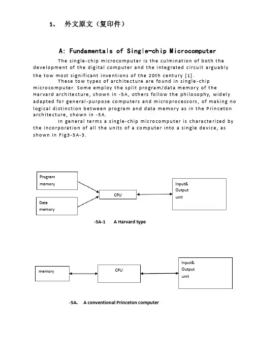
1、 外文原文(复印件)A: Fundamentals of Single-chip MicrocomputerT h e sin gle -ch ip mi c ro co m p u t e r is t h e cu lm in at io n of b ot h t h e d e ve lo p me nt of t h e d ig ita l co m p u t e r a n d t h e i nte g rated c ircu it a rgu ab l y t h e to w mo st s ign if i cant i nve nt i o n s of t h e 20t h c e nt u ry [1].T h ese to w t yp e s of arch ite ct u re are fo u n d in s in gle -ch ip m i cro co m p u te r. S o m e e mp l oy t h e sp l it p ro gra m /d at a m e m o r y of t h e H a r va rd arch ite ct u re , s h o wn in -5A , ot h e rs fo l lo w t h e p h i lo so p hy, wid e l y ad a p ted fo r ge n e ral -p u rp o se co m p u te rs an d m i cro p ro ce ss o rs , of m a kin g n o l o g i ca l d i st in ct i o n b et we e n p ro gra m an d d ata m e m o r y as in t h e P rin c eto n a rch ite ct u re , sh o wn in -5A.In ge n e ra l te r m s a s in g le -ch ip m ic ro co m p u t e r is ch a ra cte r ized b y t h e in co r p o rat io n of all t h e u n its of a co mp u te r into a s in gle d e vi ce , as s h o w n in F i g3-5A-3.-5A-1A Harvard type-5A. A conventional Princeton computerProgrammemory Datamemory CPU Input& Output unitmemoryCPU Input& Output unitResetInterruptsPowerFig3-5A-3. Principal features of a microcomputerRead only memory (ROM).RO M is u su a l l y fo r t h e p e r m an e nt , n o n -vo lat i le sto rage of an ap p l i cat io n s p ro g ram .M a ny m i c ro co m p u te rs a n d m i cro co nt ro l le rs are inte n d ed fo r h i gh -vo lu m e ap p l i cat io n s a n d h e n ce t h e e co n o m i cal man u fa c t u re of t h e d e vi ces re q u ires t h at t h e co nt e nts of t h e p ro gra m me mo r y b e co mm i ed p e r m a n e nt l y d u r in g t h e m a n u fa ct u re of c h ip s . C lea rl y, t h i s imp l ies a r i go ro u s ap p ro a ch to ROM co d e d e ve lo p m e nt s in ce ch an ges can n o t b e mad e af te r m an u fa ct u re .T h i s d e ve l o p m e nt p ro ces s m ay i nvo l ve e mu l at i o n u sin g a so p h ist icated d e ve lo p m e nt syste m wit h a h ard wa re e mu l at i o n capab i l it y as we ll as t h e u s e of p o we rf u l sof t war e to o l s.So m e m an u fa ct u re rs p ro vi d e ad d it i o n a l ROM o p t io n s b y in clu d in g in t h e i r ran ge d e v ic es w it h (o r inte n d ed fo r u s e wit h ) u se r p ro g ram m a b le m e mo r y. T h e s im p lest of t h e se i s u su a l l y d e v i ce wh i ch can o p e rat e in a m i cro p ro ce s so r mo d e b y u s in g s o m e of t h e in p u t /o u t p u t l in es as an ad d res s a n d d ata b u s fo r a cc es sin g exte rn a l m e m o r y. T h is t yp e o f d e vi ce can b e h ave f u n ct i o n al l y as t h e s in gle ch ip m i cro co m p u t e r f ro m wh i ch it i s d e ri ved a lb e it wit h re st r icted I/O an d a m o d if ied exte rn a l c ircu it. T h e u s e of t h e se RO M le ss d e vi ces i s co mmo n e ve n in p ro d u ct io n circu i ts wh e re t h e vo lu m e d o e s n ot ju st if y t h e d e ve lo p m e nt co sts of cu sto m o n -ch ip ROM [2];t h e re ca n st i ll b e a si gn if i cant sav in g in I/O an d o t h e r ch ip s co m pared to a External Timing components System clock Timer/ Counter Serial I/O Prarallel I/O RAM ROMCPUco nve nt io n al m i c ro p ro ces so r b ased circ u it. M o re exa ct re p l a ce m e nt fo rRO M d e v ice s can b e o b tain ed in t h e fo rm of va ria nts w it h 'p i g g y-b a c k'E P ROM(E rasab le p ro gramm ab le ROM )s o cket s o r d e v ice s w it h E P ROMin stead of ROM 。
毕业设计(论文)外文参考资料及译文译文题目:Kangle community Power Of Distribution in Yandu Of yancheng盐城市盐都区康乐小区配电设计学生姓名:学号: 0804110437 专业:电气工程及其自动化所在学院:机电工程学院指导教师:职称:讲师2012 年 3 月 3日Power Of community Distribution To DesignABSTRACT:The basic function of the electric power system is to transport the electric power towards customers. The l0kV electric distribution net is a key point that connects the power supply with the electricity using on the industry, business and daily-life. For the electric power, allcostumers expect to pay the lowest price for the highest reliability, but don't consider that it's self-contradictory in the co-existence of economy and reliable.To improve the reliability of the power supply network, we must increase the investment cost of the network construction But, if the cost that improve the reliability of the network construction, but the investment on this kind of construction would be worthless if the reducing loss is on the power-off is less than the increasing investment on improving the reliability .Thus we find out a balance point to make the most economic,between the investment and the loss by calculating the investment on power net and the loss brought from power-off.KEYWORDS:power supply and distribution, power distribution reliability,reactive compensation, load distributionThe revolution of electric power system has brought a new big round construction,which is pushing the greater revolution of electric power technique along with the application of new technique and advanced equipment. Especially, the combination of the information technique and electric power technique, to great ex- tent, has improved reliability on electric quality and electric supply. The technical development decreases the cost on electric construction and drives innovation of electric network. On the basis of national and internatio- nal advanced electric knowledge, the dissertation introduces the research hotspot for present electric power sy- etem as following.Firstly, This dissertation introduces the building condition of distribution automation(DA), and brings forward two typical construction modes on DA construction, integrative mode and fission mode .It emphasize the DA structure under the condition of the fission mode and presents the system configuration, the main station scheme, the feeder scheme, the optimized communication scheme etc., which is for DA research reference.Secondly, as for the (DA) trouble measurement, position, isolation and resume, This dissertation analyzes the changes of pressure and current for line problem, gets math equation by educing phase short circuit and problem position under the condition of single-phase and works out equation and several parameter s U& , s I& and e I& table on problem . It brings out optimized isolation and resume plan, realizes auto isolation and network reconstruction, reduces the power off range and time and improves the reliability of electric power supply through problem self- diagnoses and self-analysis. It also introduces software flow and use for problem judgement andsets a model on network reconstruction and computer flow.Thirdly, electricity system state is estimated to be one of the key techniques in DA realization. The dissertation recommends the resolvent of bad measurement data and structure mistake on the ground of describing state estimate way. It also advances a practical test and judging way on topology mistake in state estimate about bad data test and abnormity in state estimate as well as the problem and effect on bad data from state measure to state estimate .As for real time monitor and control problem, the dissertation introduces a new way to solve them by electricity break and exceptional analysis, and the way has been tested in Weifang DA.Fourthly, about the difficulty for building the model of load forecasting, big parameter scatter limit and something concerned, the dissertation introduces some parameters, eg. weather factor, date type and social environment effect based on analysis of routine load forecasting and means. It presents the way for electricity load forecasting founded on neural network(ANN),which has been tested it’s validity by example and made to be good practical effect.Fifthly, concerning the lack of concordant wave on preve nting concordant wave and non-power compensation and non-continuity on compensation, there is a topology structure of PWM main circuit and nonpower theory on active filter the waves technique and builds flat proof on the ground of Saber Designer and proves to be practical. Meanwhile, it analyzes and designs the way of non-power need of electric network tre- nds and decreasing line loss combined with DA, which have been tested its objective economic benefit throu- gh counting example.Sixthly, not only do the dissertation design a way founded on the magrginal electric price fitted to our present national electric power market with regards to future trends of electric power market in China and fair trade under the government surveillance, that is group competitio n in short-term trade under the way of grouped price and quantity harmony, but also puts forward combination arithmetic, math model of trading plan and safty economical restriction. It can solve the original contradiction between medium and long term contract price and short term competitive price with improvement on competitive percentage and cut down the unfair income difference of electric factory, at the same time, it can optimize the electric limit for all electric factories and reduce the total purchase charge of electric power from burthen curve of whole electric market network.The distribution network is an important link among the power system. Its neutral grounding mode and operation connects security and stability of the power system directly. At the same time, the problem about neutral grounding is associated with national conditions, natural environment, device fabrication and operation. For example, the activity situation of the thunder and lightning, insulating structure and the peripheral interference will influence the choice of neutral groundingmode Conversely, neutral grounding mode affects design, operation, debugs and developing. Generally in the system higher in grade in the voltage, the insulating expenses account for more sizable proportion at the total price of the equipment. It is very remarkable to bring the economic benefits by reducing the insulating level. Usually such system adopt the neutral directly grounding and adopt the autoreclosing to guarantee power supply reliability. On the contrary, the system which is lower in the voltage adopts neutral none grounding to raise power supply reliability. So it is an important subject to make use of new- type earth device to apply to the distribution network under considering the situation in such factors of various fields as power supply reliability, safety factor, over-voltage factor, the choice of relay protection, investment cost, etc.The main work of this paper is to research and choice the neutral grounding mode of the l0kV distribution network. The neutral grounding mode of the l0kV network mainly adopts none grounding, grounding by arc suppressing coil, grounding by reactance grounding and directly grounding. The best grounding mode is confirmed through the technology comparison. It can help the network run in safety and limit the earth electric arc by using auto-tracking compensate device and using the line protection with the detection of the sensitive small ground current. The paper introduces and analyzes the characteristic of all kind of grounding modes about l0kV network at first. With the comparison with technological and economy, the conclusion is drawn that the improved arc suppressing coil grounding mode shows a very big development potential.Then, this paper researches and introduces some operation characteristics of the arc suppressing coil grounding mode of the l0kV distribution network. And then the paper put emphasis on how to extinguish the earth electric arc effectively by utilizing the resonance principle. This paper combines the development of domestic and international technology and innovative achievement, and introduces the computer earth protection and autotracking compensate device. It proves that the improved arc suppressing coil grounding mode have better operation characteristics in power supply reliability, personal security, security of equipment and interference of communication. The application of the arc suppressing coil grounding mode is also researched in this paper.Finally, the paper summarizes this topic research. As a result of the domination of the arc suppressing coil grounding mode, it should be more popularized and applied in the distribution network in the future.The way of thinking, project and conclusions in this thesis have effect on the research to choose the neutral grounding mode not only in I0kV distribution network but also in other power system..The basic function of the electric power system is to transport the electric power towards customers. The l0kV electric distribution net is a key point that connects the power supply withthe electricity using on the industry, business and daily-life. For the electric power, all costumers expect to pay the lowest price for the highest reliability, but don't consider that it's self-contradictory in the co-existence of economy and reliable. To improve the reliability of the power supply network, we must increase the investment cost of the network con- struction But, if the cost that improve the reliability of the network construction, but the investment on this kind of construction would be worthless if the reducing loss is on the power-off is less than the increasing investment on improving the reliability .Thus we find out a balance point to make the most economic, between the investment and the loss by calculating the investment on power net and the loss brought from power-off. The thesis analyses on the economic and the reliable of the various line modes, according to the characteristics various line modes existed in the electric distribution net in foshan..First, the thesis introduces as the different line modes in the l0kV electric distribution net and in some foreign countries. Making it clear tow to conduct analyzing on the line mode of the electric distribution net, and telling us how important and necessary that analyses are.Second, it turns to the necessity of calculating the number of optimization subsection, elaborating how it influences on the economy and reliability. Then by building up the calculation mode of the number of optimization subsection it introduces different power supply projects on the different line modes in brief. Third, it carries on the calculation and analyses towards the reliability and economy of the different line modes of electric distribution net, describing drafts according by the calculation. Then it makes analysis and discussion on the number of optimization subsection.At last, the article make conclusion on the economy and reliability of different line modes, as well as, its application situation. Accordion to the actual circumstance, the thesis puts forward the beneficial suggestion on the programming and construction of the l0kV electric distribution net in all areas in foshan. Providing the basic theories and beneficial guideline for the programming design of the lOkV electric distribution net and building up a solid net, reasonable layout, qualified safe and efficiently-worked electric distribution net.References[1] Wencheng Su. Factories power supply [M]. Machinery Industry Publishing House. 1999.9[2] Jiecai Liu. Factories power supply design guidance [M]. Machinery Industry Publishing House.1999.12[3] Power supply and distribution system design specifications[S].China plans Press. 1996[4] Low-voltage distribution design specifications [S].China plans Press.1996.6译文:小区配电设计摘要:电力系统的基本功能是向用户输送电能。
西华大学毕业设计外文资料翻译附录:外文资料翻译外文资料原文:A Virtual Environment for Protective Relaying Evaluation and TestingA. P. Sakis Meliopoulos and George J. CokkinidesAbstract—Protective relaying is a fundamental discipline of power system engineering. At Georgia Tech, we offer three courses that cover protective relaying: an undergraduate course that devotes one-third of the semester on relaying, a graduate courseentitled “Power System Protection,” and a three-and-a-half-day short course for practicing engineers. To maximize student understanding and training on the concepts,theory, and technology associated with protective relaying, we have developed a number of educational tools, all wrapped in a virtual environment. The virtual environment includes a) a power system simulator, b) a simulator of instrumentation for protective relaying with visualization and animation modules, c) specific protective relay models with visualization and animation modules, and d) interfaces to hardware so that testing of actual relaying equipment can be per formed. We refer to this set of software as the “virtual power system.” The virtual power system permits the in-depth coverage of the protective relaying concepts in minimum time and maximizes student understanding. The tool is not used in a passive way. Indeed, the students actively participate with well-designed projects such as a) design and implementation of multifunctional relays, b) relay testing for specific disturbances, etc. The paper describes the virtual power system organization and “engines,” s uch as solver, visualization, and animation of protective relays, etc. It also discusses the utilization of this tool in the courses via specific application examples and student assignments.Index Terms—Algebraic companion form, animation, relaying,time-domain simulation, visualization.I. INTRODUCTIONR ELAYING has always played a very important role in the security and reliability of electric power systems. As the technology advances, relaying has become more sophisticated with many different options for improved protection of the system. It is indisputable that relaying has made significant advances with dramatic beneficial effects on the safety of systems and protection of equipment. Yet, because of the complexity of the system and multiplicity of competing factors, relaying is a challenging discipline.Despite all of the advances in the field, unintended relay operations (misoperations) do occur. Many events of outages and blackouts can be attributed to inappropriate relayingsettings, unanticipated system conditions, and inappropriate selection of instrument transformers. Design of relaying schemes strives to anticipate all possible conditions for the purpose of avoiding undesirable operations. Practicing relay engineers utilize a two-step procedure to minimize the possibility of such events. First, in the design phase, comprehensive analyses are utilized to determine the best relaying schemes and settings. Second, if such an event occurs, an exhaustive post-mortem analysis is performed to reveal the roo t cause of the event and what “was missed” in the design phase. The post-mortem analysis of these events is facilitated with the existing technology of disturbance recordings (via fault disturbance recorders or embedded in numerical relays). This process results in accumulation of experience that passes from one generation of engineers to the next.An important challenge for educators is the training of students to become effective protective relaying engineers. Students must be provided with an understanding of relaying technology that encompasses the multiplicity of the relaying functions, communications, protocols, and automation. In addition, a deep understanding of power system operation and behavior during disturbances is necessary for correct relayin g applications. In today’s crowded curricula, the challenge is to achieve this training within a very short period of time, for example, one semester. This paper presents an approach to meet this challenge. Specifically, we propose the concept of the virtual power system for the purpose of teaching students the complex topic of protective relaying within a short period of time.The virtual power system approach is possible because of two factors: a) recent developments in software engineering and visualization of power system dynamic responses, and b) the new generation of power system digital-object-oriented relays. Specifically, it is possible to integrate simulation of the power system, visualization, and animation of relay response and relay testing within a virtual environment. This approach permits students to study complex operation of power systems and simultaneously observe relay response with precision and in a short time.The paper is organized as follows: First, a brief description of the virtual power system is provided. Next, the mathematical models to enable the features of the virtual power system are presented together with the modeling approach for relays and relay instrumentation. Finally, few samples of applications of this tool for educational purposes are presented.II. VIRTUAL POWER SYSTEMThe virtual power system integrates a number of application software in a multitasking environment via a unified graphical user interface. The application software includes a) a dynamic power system simulator, b) relay objects, c) relay instrumentation objects, and d)animation and visualization objects. The virtual power system has the following features:1) continuous time-domain simulation of the system under study;2) ability to modify (or fault) the system under study during the simulation, and immediately observe the effects of thechanges;3) advanced output data visualization options such as animated 2-D or 3-D displays that illustrate the operation of any device in the system under study.The above properties are fundamental for a virtual environment intended for the study of protective relaying. The first property guarantees the uninterrupted operation of the system under study in the same way as in a physical laboratory: once a system has been assembled, it will continue to operate. The second property guarantees the ability to connect and disconnect devices into the system without interrupting the simulation of the system or to apply disturbances such as a fault. This property duplicates the capability of physical laboratories where one can connect a component to the physical system and observe the reaction immediately (e.g., connecting a new relay to the system and observing the operation of the protective relaying logic, applying a disturbance and observing the transients as well as the relay logic transients, etc.). The third property duplicates the ability to observe the simulated system operation, in a similar way as in a physical laboratory. Unlike the physical laboratory where one cannot observe the internal operation of a relay, motor, etc., the virtual power system has the capability to provide a visualization and animation of the internal “workings” of a relay, motor, etc. This capability to animate and visualize the internal “workings” o f a relay, an instrumentation channel, or any other device has substantial educational value.The virtual power system implementation is based on the MS Windows multidocument-viewarchitecture. Each document object constructs a single solver object, which handles the simulation computations. The simulated system is represented by a set of objects—one for each system device (i.e. generators, motors, transmission lines, relays, etc). The document object can generate any number of view window objects. Two basic view classes are available: a) schematic views and b) result visualization views. Schematic view objects allow the user to define the simulated system connectivity graphically, by manipulating a single line diagram using the mouse. Result visualization views allow the user to observe calculated results in a variety of ways. Several types of result visualization views are supported and will be discussed later.Fig. 1 illustrates the organization of device objects, network solver, and view objects and their interactions. The network solver object is the basic engine that provides the time-domain solution of the device operating conditions. To maintain object orientation, each device isrepresented with a generalized mathematical model of a specific structure, the algebraic companion form (ACF). The mathematics of the algebraic companion form are described in the next section. Implementationwise, the network solver is an independent background computational thread, allowing both schematic editor and visualization views to be active during the simulation. The network solver continuously updates the operating states of the devices and “feeds” all other applications, such as visualization views,etc.The network solver speed is user selected, thus allowing speeding-up or slowing-down the visualization and animation speed. The multitasking environment permits system topology changes, device parameter changes, or connection of new devices (motors, faults) to the system during the simulation. In this way, the user can immediately observe the system response in the visualization views.The network solver interfaces with the device objects. This interface requires at minimum three virtual functions:Initialization: The solver calls this function once before the simulation starts. It initializes all device-dependent parameters and models needed during the simulation.Reinitialization: The solver calls this function any time the user modifies any device parameter. Its function is similar to the initialization virtual function.Time step: The solver calls this function at every time step of the time-domain simulation. It transfers the solution from the previous time step to the device object and updates the algebraic companion form of the device for the next time step (see next section “network solver.”)In addition to the above functions, a device object has a set of virtual functions comprising the schematic module interface. These functions allow the user to manipulate the device within the schematic editor graphical user interface. Specifically,the device diagram can be moved, resized, and copied using the mouse. Also, a function is included in this set, which implements a device parameter editing dialog window which “pops-up” by double clicking on the device icon. Furthermore,the schematic module interface allows for device icons that reflect the device status. For example, a breaker schematic icon can be implemented to indicate the breaker status.Finally, each device class (or a group of device classes) may optionally include a visualization module, consisting of a set of virtual functions that handle the visualization and animation output. The visualization module interface allows for both two-dimensional (2-D) and three-dimensional (3-D) graphics. Presently, 2-D output is implemented via the Windows graphical device interface (GDI) standard. The 3-D output is implemented using the opengraphics library (OpenGL). Both 2-D and 3-D outputs generate animated displays, which are dynamically updated by the network solver to reflect the latest device state. The potential applications of 2-D or 3-D animated visualization objects are only limited by the imagination of the developer. These objects can generate photorealistic renderings of electromechanical components that clearly illustrate their internal operation and can be viewed from any desired perspective,slowed down, or paused for better observation.III. NETWORK SOLVERAny power system device is described with a set of algebraicdifferential-integral equations. These equations are obtained directlyfrom the physical construction of the device. It is alwayspossible to cast these equations in the following general formNote that this form includes two sets of equations, which arenamed external equations and internal equations, respectively.The terminal currents appear only in the external equations.Similarly, the device states consist of two sets: external states[i.e., terminal voltages, v(t)] and internal states [i.e. y(t)]. Theset of (1) is consistent in the sense that the number of externalstates and the number of internal states equals the number of externaland internal equations, respectively.Note that (1) may contain linear and nonlinear terms. Equation(1) is quadratized (i.e., it is converted into a set of quadraticequations by introducing a series of intermediate variables and expressing the nonlinear components in terms of a series of quadratic terms). The resulting equations are integrated using a suitable numerical integration method. Assuming an integration time step h, the result of the integration is given with a second-order equation of the formwhere , are past history functions.Equation (2) is referred to as the algebraic companion form (ACF) of the device model. Note that this form is a generalizationof the resistive companion form (RCF) that is used by the EMTP [3]. The difference is that the RCF is a linear model that represents a linearized equivalent of the device while the ACF is quadratic and represents the detailed model of the device.The network solution is ob tained by application of Kirchoff’s current law at each node of the system (connectivity constraints). This procedure results in the set of (3). To these equations, the internal equations are appended resulting to the following set of equations:(3)internal equations of all devices (4)where is a component incidence matrix withif node of component is connected to node otherwise is the vector of terminal currents of component k.Note that (3) correspond one-to-one with the external system states while (4) correspond one-to-one with the internal system states. The vector of component k terminal voltages is related to the nodal voltage vector by(5)Upon substitution of device (2), the set of (3) and (4)become a set of quadratic equations (6)where x(t) is the vector of all external and internal system states.These equations are solved using Newton’s method. Specifically,the solution is given by the following expression(7)where is the Jacobian matrix of (6) and are the values ofthe state variables at the previous iteration.IV. RELAY INSTRUMENTATION MODELINGRelays and, in general, IEDs use a system of instrument transformers to scale the power system voltages and currents into instrumentation level voltages and currents. Standard instrumentation level voltages and currents are 67 V or 115 V and 5 A, respectively. These standards were established many years ago to accommodate the electromechanical relays. Today, the instrument transformers are still in use but because modern relays (and IEDs) operate at much lower voltages, it is necessary to apply an additional transformation to the new standard voltages of 10 or 2 V. This means that the modern instrumentation channel consists of typically two transformations and additional wiring and possibly burdens. Fig. 2 illustrates typical instrumentation channels, a voltage channel and a current channel. Note that each component of the instrumentation channel will introduce an error. Of importance is the net error introduced by all of the components of the instrumentation channel. The overallerror can be defined as follows. Let the voltage or current at the power system be and , respectively. An ideal instrumentation channel will generate a waveform at the output of the channel that will be an exact replica of the waveform at the power system. If the nominal transformation ratio is and for the voltage and current instrumentation channels, respectively, then the output of an “ideal” system and the instrumentation channel error will bewhere the subscript “out” refers to the actual output of the instrumentation channel. The error waveforms can be analyzed to provide the rms value of the error, the phase error, etc.Any relaying course should include the study of instrumentation channels. The virtual power system is used to study the instrumentation error by including an appropriate model of the entire instrumentation channel. It is important to model the saturation characteristics of CTs and PTs, resonant circuits of CCVTs, etc. (see [6]). In the virtual power system, models of instrumentation channel components have been developed. The resulting integrated model provides, with precision, the instrumentation channel error.With the use of animation methods, one can study the evolution of instrumentation errors during transients as well as normal operation.V. PROTECTIVE RELAY MODELINGToday, all new relays are numerical relays. These types of relays can be easily modeled within the virtual power system. Consider, for example, a directional relay. The operation ofthis relay is based on the phase angle between the polarizing voltage and the current. Modeling of this relay then requires that the phase angle between the polarizing voltage and the current be computed. For this purpose, as the power system simulation progresses, the relay model retrieves the instantaneous values of the polarizing voltage and the current. A Fourier transform is applied to the retrieved data (a running time Fourier transform over a user-specified time window). The result will be the phasors of the polarizing voltage and current from which the phase angles are retrieved. The directional element of the relay will trip if the phase angle difference is within the operating region. It should be also self understood that if the relay to be modeled has filters, these filters can be also included in the model.It is important that students be also involved in the design of numerical relays. A typical semester project is to define the functionality of a specific relay and a set of test cases. The student assignment is to develop the code that will mimic the operation of the relay and demonstrate its correct operation for the test cases.The new technology of the virtual power system offers another more practical way to model relays. The virtual power system uses object-oriented programming. As such, it is an open architecture and can accept dynamic link libraries of third parties. A natural extension of the work reported in this paper is to use this feature to interface with commercially available digital “relays.” The word “relay” is in quotation marks to indicate that the relay is simply a digital program that takes inputs of voltages and currents, performs an analysis of these data, applies logic, and issues a decision. This program is an object and can be converted into a dynamic link library. If this DLL is “linked” with the virtual power system, in the sense that the inputs come from the virtual power system, then the specific relay can be evaluated within the virtual environment. The technology for this approach is presently available. Yet, our experience is that relay manufacturers are not presently perceptive in making their “relay” objects available as DLLs that can be interfaced with third-party software.VI. APPLICATIONSThe described virtual environment has been used in a variety of educational assignments. The possible uses are only limited by the imagination of the educator. In this section, we describe a small number of educational application examples.Figs. 3 and 4 illustrate an exercise of studying instrumentation channel performance. Fig. 3 illustrates an example integrated model of a simple power system and the model of an instrumentation channel (voltage). The instrumentation channel consists of a PT, a length of control cable, an attenuator, and an A/D converter (Fig. 3 illustrates the icons of thesecomponents and their interconnection). Fig. 4 illustrates two waveforms: the voltage of phase A of the power system when it is experiencing a fault and the error of the instrumentation channel. The upper part of the figure illustrates the actual voltage of Phase A and the output of the instrumentation channel (multiplied by the nominal transformation ratio). The two traces are quite close. The lower part of the figure illustrates the error between the two waveforms of the upper part of the figure. The two curves illustrate the normalized error at the input of the A/D converter and at the output of the A/D converter. The figure is self-explanatory and a substantial error occurs during the transient of the fault. When the transients subside, the error of the instrumentation channel is relatively small. The intention of this exercise is to study the effects of different parameters of the instrumentation channel.For example, the students can change the length of the control cable and observe the impact on the error. Or in case of a current channel, they can observe the effects of CT saturation on the error of the instrumentation channel, etc.Fig. 5 illustrates the basics of an example application of the virtual power system for visualization and animation of a modified impedance relay. The example system consists of a generator, a transmission line, a step-down transformer, a passive electric load (constant impedance load), an induction motor, and a mechanical load of the motor (fan). A modified distance relay (mho relay) monitors the transmission line. The operation of this relay is based on the apparent impedance that the relay “sees” and the trajectory of this impedance.The visualization object of this relay displays what the relay “sees” during a disturbance in the system and superimposes this information on the relay settings. Typical examples are illustrated in Figs. 6 and 7. The relay monitors the three-phase voltages and currents at the point of its application. The animation model retrieves the information that the relay monitors from the simulator at each time step. Subsequently, it computes the phasors of the voltages and currents as well as the sequence components of these voltages and currents. Fig. 6 illustrates a 2-D visualization of the operation of this relay over a period that encompasses a combined event of an induction motor startup followed by a single-phase fault on the high-voltage side of the transformer. (This example demonstrates the flexibility of the tool to generate composite events that may lead to very interesting responses of the protective relays). The left-hand side of the 2-Dvisualization shows the voltages and currents “seen” by the relay(the snapshot is after the fault has been cleared). The graph also shows the trajectory (history) of the impedance “seen” by the relay. The graph shows the trajectory “seen” over a user-specified time interval preceding present time. The impedance trajectory is superimposed on the trip characteristics of this relay. In this case, the impedance trajectory does not visit thetrip “region” of the relay.Fig. 7 provides the recorded impedance trajectory for the combined event of an induction motor startup followed by a three-phase fault near the low-voltage bus of the transformer. The impedance trajectory is superimposed on the trip characteristics of this relay. In this case, the impedance trajectory does visit the trip “region” of the relay. This example can be extended to more advanced topics. For example, the animated display may also include stability limits for the “swing” of the generator. For this purpose, the stability limits for the particular condition must be computed and displayed.This exercise can be the topic of a term project.Another important protective relaying example is the differential relay. In this example, we present the animated operation of a differential relay scheme for a delta-wye connected transformer with tap changing under load. The example system is shown in Fig. 8. It consists of an equivalent source, a transmission line, a 30-MVA delta-wye connected transformer, a distribution line, and an electric load. A transformer differential relay Fig. 7. Animation of a mho relay for a three phase fault on the 13.8-kV bus. is protecting the transformer. The differential relay has as inputs the transformer terminal currents. A specific implementation of a differential relay visualization is shown in Fig. 9 based on the electromechanical equivalent relay. Note that the 2-D visualization shows t he “operating” coils and “restraining” coils and the currents that flow in these coils at any instant of time. Instantaneous values, rms values, and phasor displays are displayed. Fig. 9 illustrates one snapshot of the system. In reality, as the system operation progresses, this figure is continuously updated, providing an animation effect. The system may operate under steady-state or under transient conditions. The effects of tap changing on the operation of the relay are demonstrated. The importance of this animation module is that one can study the effects of various parameters and phenomena on the operation of the relay. Examples are: a) effects of tap setting. The differential relay settings are typically selected for the nominal tap setting. As the tap setting changes under load, the current in the operating coil changes and may be nonzero even under normal operating conditions. It is very easy to change the tap setting andobserve the operation of the relay in an animated fashion. It is also easy to observe the operation of the relay during a through fault for different values of tap settings. Thus, this tool is very useful in determining the optimal level of percent restraint for the relay. b) effects of inrush currents. One can perform energization simulations of the transformer by various types of breaker-closing schemes. Since the transformer model includes the nonlinear magnetization model of the transformer core, the magnetization inrush currents will appear in the terminals of the transformer and, therefore, in the differential relay. The display of Fig. 9 provides a full picture of the evolutionof the electric currents. One can study the effects of inrush currents by bypassing the even harmonic filters as well as by implementing a number of harmonic filters and observing the effectiveness of the filters. It is important to note that the phenomena involved are very complex, yet a student can study these phenomena indepth and in very short time with the aid of animation and visualization methods.The virtual power system has been also used for testing of physical relays. This application is quite simple. The virtual power system has the capability to export voltage and current waveforms of any event and for any user-selected time period in COMTRADE format. Then, the COMTRADE file is fed into commercial equipment that generates the actual voltages and currents and feeds them into the physical relays. The actual response of the relays is then observed. This application was performed on the premises of a utility with limited access to students.Recently, a major relay manufacturer (SEL) has donated equipment to Georgia Tech and we are in the process of setting up the laboratory for routine use of this function by students. There are numerous other applications of the proposed virtual power system. The pedagogical objective is to instill a deep understanding of protective relaying concepts and problems in the very short time of one semester. The effectiveness of the proposed approach increases as new examples are generated and stored in the database.Aclassical example that demonstrates the effectiveness of the virtual power system is the issue of sympathetic tripping. Usually, this topic requires several lectures and long examples. With the virtual power system, one can very thoroughly teach the concept of sympathetic tripping within onelecture. For example, a simple system with mutually coupled lines can be prepared, with relays at the ends of all lines. Then with a fault in one line, the relays of the healthy line can be visualized and animated. The students can observe that the relays of the healthy line “see” zero-sequence current induced by the fault on another line. And more important, the students can make changes to the designs of the lines and observe the relative effect of design parameters on induced voltages and currents, etc.VII. CONCLUSIONThis paper has discussed and presented the virtual power system and its application for visualization and animation of protective relaying. The virtual power system has proved to be a valuable tool in the instruction of protective relaying courses. It is also an excellent tool for assigning term projects on various aspects of protective relaying. One important feature of the tool is that the user can apply disturbances to the system while the system operates (i.e., faults, load shedding, motor start-up, etc.). The response of the relays is instantaneously observed.。

电气工程英语作文模板英文回答:Introduction。
Electrical engineering is a vast and complex field that encompasses the generation, transmission, distribution, and utilization of electrical energy. It plays a vital role in modern society, powering everything from our homes and businesses to our transportation and communication systems.Major Branches of Electrical Engineering。
The field of electrical engineering can be broadly divided into several major branches, each with its own specialized focus:Power engineering deals with the generation, transmission, and distribution of electrical power.Control engineering involves the design and analysis of systems that control electrical processes.Electronics engineering focuses on the design and development of electronic devices and circuits.Telecommunications engineering deals with the transmission and reception of information over electrical channels.Computer engineering combines electrical engineering principles with computer science to design and develop computer systems.Applications of Electrical Engineering。
优秀论文审核通过未经允许切勿外传Chapter 3 Digital Electronics3.1 IntroductionA circuit that employs a numerical signal in its operation is classified as a digital circuitputers,pocket calculators, digital instruments, and numerical control (NC) equipment are common applications of digital circuits. Practically unlimited quantities of digital information can be processed in short periods of time electronically. With operational speed of prime importance in electronics today,digital circuits are used more frequently.In this chapter, digital circuit applications are discussed.There are many types of digital circuits that electronics, including logic circuits, flip-flop circuits, counting circuits, and many others. The first sections of this unit discuss the number systems that are basic to digital circuit understanding. The remainder of the chapter introduces some of the types of digital circuits and explains Boolean algebra as it is applied to logic circuits.3.2 Digital Number SystemsThe most common number system used today is the decimal system,in which 10 digits are used for counting. The number of digits in the systemis called its base (or radix).The decimal system,therefore,the counting process. The largest digit that can be used in a specific place or location is determined by the base of the system. In the decimal system the first position to the left of the decimal point is called the units place. Any digit from 0 to 9 can be used in this place.When number values greater than 9 are used,they must be expressed with two or more places.The next position to the left of the units place in a decimal system is the tens place.The number 99 is the largest digital value that can be expressed by two places in the decimal system.Each place added to the left extends the number system by a power of 10.Any number can be expressed as a sum of weighted place values.The decimal number 2583,for example, is expressed as (2×1000)+(5×100)+(8×10)+(3×1).The decimal number system is commonly used in our daily lives. Electronically, the binary system.Electronically,the value of 0 can be associated with a low-voltage value or no voltage. The number 1 can then be associated with a voltage value larger than 0. Binary systems that use these voltage values are said to , this chapter.The two operational states of a binary system,1 and 0,are natural circuit conditions. When a circuit is turned off or the off, or 0,state. An electrical circuit that the on,or 1,state. By using transistor or ICs,it is electronically possible to change states in less than a microsecond. Electronic devices make it possible to manipulate millions of 0s and is in a second and thus to process information quickly.The basic principles of numbering used in decimal numbers apply ingeneral to binary numbers.The base of the binary system is 2,meaning that only the digits 0 and 1 are used to express place value. The first place to the left of the binary point,or starting point,represents the units,or is,location. Places to the left of the binary point are the powers of 2.Some of the place values in base 2 are 2º=1,2¹=2,2²=4,2³=8,2⁴=16,25=32,and 26=64.When bases other than 10 are used,the numbers should example.The number 100₂(read“one,zero,zero, base 2”)is equivalent to 4 in base 10,or 410.Starting with the first digit to the left of the binary point,this number this method of conversion a binary number to an equivalent decimal number,write down the binary number first. Starting at the binary point,indicate the decimal equivalent for each binary place location where a 1 is indicated. For each 0 in the binary number leave a blank space or indicate a 0 ' Add the place values and then record the decimal equivalent.The conversion of a decimal number to a binary equivalent is achieved by repetitive steps of division by the number 2.When the quotient is even with no remainder,a 0 is recorded.When the quotient process continues until the quotient is 0.The binary equivalent consists of the remainder values in the order last to first.3.2.2 Binary-coded Decimal (BCD) Number SystemWhen large numbers are indicated by binary numbers,they are difficult to use. For this reason,the Binary-Coded Decimal(BCD) method of counting was devised. In this system four binary digits are used to represent each decimal digit.To illustrate this procedure,the number 105,is converted to a BCD number.In binary numbers,To apply the BCD conversion process,the base 10 number is first divided into digits according to place values.The number 10510 gives the digits 1-0-5.Converting each displayed by this process with only 12 binary numbers. The between each group of digits is important when displaying BCD numbers.The largest digit to be displayed by any group of BCD numbers is 9.Six digits of a number-coding group are not used at all in this system.Because of this, the octal (base 8) and the binary form but usually display them in BCD,octal,or a base 8 system is 7. The place values starting at the left of the octal point are the powers of eight: 80=1,81=8,82=64,83=512,84=4096,and so on.The process of converting an octal number to a decimal number is the same as that used in the binary-to-decimal conversion process. In this method, equivalent decimal is 25810.Converting an octal number to an equivalent binary number is similar to the BCD conversion process. The octal number is first divided into digits according to place value. Each octal digit is then converted into an equivalent binary number using only three digits.Converting a decimal number to an octal number is a process of repetitive division by the number 8.After the quotient determined,the remainder is brought down as the place value.When the quotient is even with no remainder,a 0 is transferred to the place position.The number for converting 409810 to base 8 is 100028.Converting a binary number to an octal number is an importantconversion process of digital circuits. Binary numbers are first processed at a very output circuit then accepts this signal and converts it to an octal signal displayed on a readout device.must first be divided into groups of three,starting at the octal point.Each binary group is then converted into an equivalent octal number.These numbers are then combined,while remaining in their same respective places,to represent the equivalent octal number.3.2.4 Hexadecimal Number SystemThe digital systems to process large number values.The base of this system is 16,which means that the largest number used in a place is 15.Digits used by this system are the numbers 0-9 and the letters A-F. The letters A-P are used to denote the digits 10-15,respectively. The place values to the left of the .The process of changing a proper digital order.The place values,or powers of the base,are then positioned under the respective digits in step 2.In step 3,the value of each digit is recorded. The values in steps 2 and 3 are then multiplied together and added. The sum gives the decimal equivalent value of a . Initially,the converted to a binary number using four digits per group. The binary group is combined to form the equivalent binary number.The conversion of a decimal number to a ,as with other number systems. In this procedure the division is by 16 and remainders can be as large as 15.Converting a binary number to a groups of four digits,starting at the converted to a digital circuit-design applications binary signals arefar superior to those of the octal,decimal,or be processed very easily through electronic circuitry,since they can be represented by two stable states of operation. These states can be easily defined as on or off, 1 or 0,up or down,voltage or no voltage,right or left,or any other two-condition states. There must be no in-between state.The symbols used to define the operational state of a binary system are very important.In positive binary logic,the state of voltage,on,true,or a letter designation (such as A ) is used to denote the operational state 1 .No voltage,off,false,and the letter A are commonly used to denote the 0 condition. A circuit can be set to either state and will remain in that state until it is caused to change conditions.Any electronic device that can be set in one of two operational states or conditions by an outside signal is said to be bistable. Relays,lamps,switches,transistors, diodes and ICs may be used for this purpose. A bistable device .By using many of these devices,it is possible to build an electronic circuit that will make decisions based upon the applied input signals. The output of this circuit is a decision based upon the operational conditions of the input. Since the application of bistable devices in digital circuits makes logical decisions,they are commonly called binary logic circuits.If we were to draw a circuit diagram for such a system,including all the resistors,diodes,transistors and interconnections,we would face an overwhelming task, and an unnecessary one.Anyone who read the circuit diagram would in their mind group the components into standard circuits and think in terms of the" system" functions of the individual gates. Forthis reason,we design and draw digital circuit with standard logic symbols. Three basic circuits of this type are used to make simple logic decisions.These are the AND circuit, OR circuit, and the NOT circuit.Electronic circuits designed to perform logic functions are called gates.This term refers to the capability of a circuit to pass or block specific digital signals.The logic-gate symbols are shown in Fig.3-1.The small circle at the output of NOT gate indicates the inversion of the signal. Mathematically,this action is described as A=.Thus without the small circle,the rectangle would represent an amplifier (or buffer) with a gain of unity.An AND gate the 1 state simultaneously,then there will be a 1 at the output.The AND gate in Fig. 3-1 produces only a 1 out-put when A and B are both 1. Mathematically,this action is described as A·B=C. This expression shows the multiplication operation. An OR gate Fig.3-1 produces a when either or both inputs are l.Mathematically,this action is described as A+B=C. This expression shows OR addition. This gate is used to make logic decisions of whether or not a 1 appears at either input.An IF-THEN type of sentence is often used to describe the basic operation of a logic state.For example,if the inputs applied to an AND gate are all 1,then the output will be 1 .If a 1 is applied to any input of an OR gate,then the output will be 1 .If an input is applied to a NOT gate,then the output will be the opposite or inverse.The logic gate symbols in Fig. 3-1 show only the input and output connections. The actual gates,when wired into a digital circuit, would pin 14 and 7.3.4 Combination Logic GatesWhen a NOT gate is combined with an AND gate or an OR gate,it iscalled a combination logic gate. A NOT-AND gate is called a NAND gate,which is an inverted AND gate. Mathematically the operation of a NAND gate is A·B=. A combination NOT-OR ,or NOR,gate produces a negation of the OR function.Mathematically the operation of a NOR gate is A+B=.A 1 appears at the output only when A is 0 and B is 0.The logic symbols are shown in Fig. 3-3.The bar over C denotes the inversion,or negative function,of the gate.The logic gates discussed .In actual digital electronic applications,solid-state components are ordinarily used to accomplish gate functions.Boolean algebra is a special form of algebra that was designed to show the relationships of logic operations.Thin form of algebra is ideally suited for analysis and design of binary logic systems.Through the use of Boolean algebra,it is possible to write mathematical expressions that describe specific logic functions.Boolean expressions are more meaningful than complex word statements or or elaborate truth tables.The laws that apply to Boolean algebra are used to simplify complex expressions. Through this type of operation it may be possible to reduce the number of logic gates needed to achieve a specific function before the circuits are designed.In Boolean algebra the variables of an equation are assigned by letters of the alphabet.Each variable then exists in states of 1 or 0 according to its condition.The 1,or true state,is normally represented by a single letter such as A,B or C.The opposite state or condition is then described as 0,or false,and is represented by or A’.This is described as NOT A,A negated,or A complemented.Boolean algebra is somewhat different from conventional algebra withrespect to mathematical operations.The Boolean operations are expressed as follows:Multiplication:A AND B,AB,,A·BOR addition:A OR B .A+BNegation,or complementing:NOT A,,A’Assume that a digital logic circuit only C is on by itself or when A,B and C are all on expression describes the desired output. Eight (23) different combinations of A,B,and C exist in this expression because there are three,inputs. Only two of those combinations should cause a signal that will actuate the output. When a variable is not on (0),it is expressed as a negated letter. The original statement is expressed as follows: With A,B,and C on or with A off, B off, and C on ,an output (X)will occur:ABC+C=XA truth table illustrates if this expression is achieved or not.Table 3-1 shows a truth table for this equation. First,ABC is determined by multiplying the three inputs together.A 1 appears only when the A,B,and C inputs are all 1.Next the negated inputs A andB are determined.Then the products of inputs C,A,and B are listed.The next column shows the addition of ABC and C.The output of this equation shows that output 1 is produced only when C is 1 or when ABC is 1.A logic circuit to accomplish this Boolean expression is shown in Fig. 3-4.Initially the equation is analyzed to determine its primary operational function.Step1 shows the original equation.The primary function is addition,since it influences all parts of the equation in some way.Step 2 shows the primary function changed to a logic gate diagram.Step 3 showsthe branch parts of the equation expressed by logic diagram,with AND gates used to combine terms.Step 4 completes the process by connecting all inputs together.The circles at inputs,of the lower AND gate are used to achieve the negative function of these branch parts.The general rules for changing a Boolean equation into a logic circuit diagram are very similar to those outlined.Initially the original equation must be analyzed for its primary mathematical function.This is then changed into a gate diagram that is inputted by branch parts of the equation.Each branch operation is then analyzed and expressed in gate form.The process continues until all branches are completely expressed in diagram formmon inputs are then connected together.3.5 Timing and Storage ElementsDigital electronics involves a number of items that are not classified as gates.Circuits or devices of this type the operation of a system.Included in this system are such things as timing devices,storage elements,counters,decoders,memory,and registers.Truth tables symbols,operational characteristics,and applications of these items will be presented an IC chip. The internal construction of the chip cannot be effectively altered. Operation is controlled by the application of an external signal to the input. As a rule,very little work can be done to control operation other than altering the input signal.The logic circuits in Fig. 3-4 are combinational circuit because the output responds immediately to the inputs and there is no memory. When memory is a part of a logic circuit,the system is called sequential circuit because its output depends on the input plus its an input signal isapplied.A bistable multivibrator,in the strict sense,is a flip-flop. When it is turned on,it assumes a particular operational state. It does not change states until the input is altered.A flip-flop opposite polarity.Two inputs are usually needed to alter the state of a flip-flop. A variety of names are used for the inputs.These vary a great deal between different flip-flops.1. R-S flip-flopsFig.3-5 shows logic circuit construction of an R-S flip-flop. It is constructed from two NAND gates. The output of each NAND provides one of the inputs for the other NAND. R stands for the reset input and S represents the set input.The truth table and logic symbol are shown in Fig. 3-6.Notice that the truth table is somewhat more complex than that of a gate. It shows, for example,the applied input, previous output,and resulting output.To understand the operation of an R-S flip-flop,we must first look at the previous outputs.This is the status of the output before a change is applied to the input. The first four items of the previous outputs are Q=1 and =0. The second four states this case of the input to NANDS is 0 and that is 0,which implies that both inputs to NANDR are 1.By symmetry,the logic circuit will also stable with Q0 and 1.If now R momentarily becomes 0,the output of NANDR,,will rise to resulting in NANDS be realized by a 0 at S.The outputs Q and are unpredictable when the inputs R and S are 0 states.This case is not allowed.Seldom would individual gates be used to construct a flip-flop,rather than one of the special types for the flip-flop packages on a single chipwould be used by a designer.A variety of different flip-flops are used in digital electronic systems today. In general,each flip-flop type R-S-T flip-flop for example .is a triggered R-S flip-flop. It will not change states when the R and S inputs assume a value until a trigger pulse is applied. This would permit a large number of flip-flops to change states all at the same time. Fig. 3-7 shows the logic circuit construction. The truth table and logic symbol are shown in Fig. 3-8. The R and S input are thus active when the signal at the gate input (T) is 1 .Normally,such timing,or synchronizing,signals are distributed throughout a digital system by clock pulses,as shown in Fig. 3-9.The symmetrical clock signal provides two times each period.The circuit can be designed to trigger at the leading or trailing edge of the clock. The logic symbols for edge trigger flip-flops are shown in Fig.3-10.2. J-K flip-flopsAnother very important flip-flop unpredictable output state. The J and K inputs addition to this,J-K flip-flops may employ preset and preclear functions. This is used to establish sequential timing operations. Fig.3-11 shows the logic symbol and truth table of a J-K flip-flop.3. 5. 2 CountersA flip-flop be used in switching operations,and it can count pulses.A series of interconnected flip-flops is generally called a register.Each register can store one binary digit or bit of data. Several flip-flops connected form a counter. Counting is a fundamental digital electronic function.For an electronic circuit to count,a number of things must beachieved. Basically,the circuit must be supplied with some form of data or information that is suitable for processing. Typically,electrical pulses that turn on and off are applied to the input of a counter. These pulses must initiate a state change in the circuit when they are received. The circuit must also be able to recognize where it is in counting sequence at any particular time. This requires some form of memory. The counter must also be able to respond to the next number in the sequence. In digital electronic systems flip-flops are primarily used to achieve counting. This type of device is capable of changing states when a pulse is applied,output pulse.There are several types of counters used in digital circuitry today.Probably the most common of these is the binary counter.This particular counter is designed to process two-state or binary information. J-K flip-flops are commonly used in binary counters.Refer now to the single J-K flip-flop of Fig. 3-11 .In its toggle state,this flip-flop is capable of achieving counting. First,assume that the flip-flop is in its reset state. This would cause Q to be 0 and Q to be 1 .Normally,we are concerned only with Q output in counting operations. The flip-flop is now connected for operation in the toggle mode. J and K must both be made the 1 state. When a pulse is applied to the T,or clock,input,Q changes to 1.This means that with one pulse applied,a 1 is generated in the output. The flip-flop the next pulse arrives,Q resets,or changes to 0. Essentially,this means that two input pulses produce only one output pulse. This is a divide-by-two function.For binary numbers,counting is achieved by a number of divide-by-two flip-flops.To count more than one pulse,additional flip-flops must be employed. For each flip-flop added to the counter,its capacity is increased by the power of 2. With one flip-flop the maximum count was 20,or 1 .For two flip-flops it would count two places,such as 20 and 21.This would reach a count of 3 or a binary number of 11.The count would be 00,01,10,and 11. The counter would then clear and return to 00. In effect, this counts four state changes. Three flip-flops would count three places,or 20,21,and 22.This would permit a total count of eight state changes.The binary values are 000,001,010,011,100,101,110 and 111.The maximum count is seven,or 111 .Four flip-flops would count four places,or 20,21,22,and 23.The total count would make 16 state changes. The maximum count would be 15,or the binary number 1111.Each additional flip-flop would cause this to increase one binary place.河南理工大学电气工程及其自动化专业中英双语对照翻译。
电气工程的外文文献(及翻译)文献一:Electric power consumption prediction model based on grey theory optimized by genetic algorithms本文介绍了一种基于混合灰色理论与遗传算法优化的电力消耗预测模型。
该模型使用时间序列数据来建立模型,并使用灰色理论来解决数据的不确定性问题。
通过遗传算法的优化,模型能够更好地预测电力消耗,并取得了优异的预测结果。
此模型可以在大规模电力网络中使用,并具有较高的可行性和可靠性。
文献二:Intelligent control for energy-efficient operation of electric motors本文研究了一种智能控制方法,用于电动机的节能运行。
该方法提供了一种更高效的控制策略,使电动机能够在不同负载条件下以较低的功率运行。
该智能控制使用模糊逻辑方法来确定最佳的控制参数,并使用遗传算法来优化参数。
实验结果表明,该智能控制方法可以显著降低电动机的能耗,节省电能。
文献三:Fault diagnosis system for power transformers based on dissolved gas analysis本文介绍了一种基于溶解气体分析的电力变压器故障诊断系统。
通过对变压器油中的气体样品进行分析,可以检测和诊断变压器内部存在的故障类型。
该系统使用人工神经网络模型来对气体分析数据进行处理和分类。
实验结果表明,该系统可以准确地检测和诊断变压器的故障,并有助于实现有效的维护和管理。
文献四:Power quality improvement using series active filter based on iterative learning control technique本文研究了一种基于迭代研究控制技术的串联有源滤波器用于电能质量改善的方法。

毕业设计(论文)外文资料翻译专业名称:电力系统自动化英文资料:INDUCTION MOTOR STARTING METHODSAbstract -Many methods can be used to start large AC induction motors. Choices such as full voltage, reduced voltage either by autotransformer or Wyes - Delta, a soft starter, or usage of an adjustable speed drive can all have potential advantages and trade offs. Reduced voltage starting can lower the starting torque and help prevent damage to the load. Additionally, power factor correction capacitors can be used to reduce the current, but care must be taken to size them properly. Usage of the wrong capacitors can lead to significant damage. Choosing the proper starting method for a motor will include an analysis of the power system as well as the starting load to ensure that the motor is designed to deliver the needed performance while minimizing its cost. This paper will examine the most common starting methods and their recommended applications.I. INTRODUCTIONThere are several general methods of starting induction motors: full voltage, reduced voltage, wyes-delta, and part winding types. The reduced voltage type can include solid state starters, adjustable frequency drives, and autotransformers. These, along with the full voltage, or across the line starting, give the purchaser a large variety of automotives when it comes to specifying the motor to be used in a given application. Each method has its own benefits, as well as performance trade offs. Proper selection will involve a thorough investigation of any power system constraints, the load to be accelerated and the overall cost of the equipment.In order for the load to be accelerated, the motor must generate greater torque than the load requirement. In general there are three points of interest on the motor's speed-torque curve. The first is locked-rotor torque (LRT) which is the minimum torque which the motor will develop at rest for all angular positions of the rotor. The second is pull-up torque (PUT) which is defined as the minimum torque developed by the motor during the period of acceleration from rest to the speed at which breakdown torque occurs. The last is the breakdown torque (BDT) which is defined as the maximum torque which the motor will develop. If any of these points are below the required load curve, then the motor will not start.The time it takes for the motor to accelerate the load is dependent on the inertia of the load and the margin between the torque of the motor and the load curve, sometimes called accelerating torque. In general, the longer the time it takes for the motor to accelerate the load, the more heat that will be generated in the rotor bars, shorting ring and the stator winding. This heat leads to additional stresses in these parts and can have an impaction motor life.II. FULL VOLTAGEThe full voltage starting method, also known as across the line starting, is the easiest method to employ, has the lowest equipment costs, and is the most reliable. This method utilizes a control to close a contactor and apply full line voltage to the motor terminals. This method will allow the motor to generate its highest starting torque and provide the shortest acceleration times.This method also puts the highest strain on the power system due to the high starting currents that can be typically six to seven times the normal full load current of the motor. If the motor is on a weak power system, the sudden high power draw can cause a temporary voltage drop, not only at the motor terminals, but the entire power bus feeding the starting motor. This voltage drop will cause a drop in the starting torque of the motor, and a drop in the torque of any other motor running on the power bus. The torque developed by an induction motor varies roughly as the square of the applied voltage. Therefore, depending on the amount of voltage drop, motors running on this weak power bus could stall. In addition, many control systems monitor under voltage conditions, a second potential problem that could take a running motor offline during a full voltage start. Besides electrical variation of the power bus, a potential physical disadvantage of an across the line starting is the sudden loading seen by the driven equipment. This shock loading due to transient torques which can exceed 600% of the locked rotor torque can increase the wear on the equipment, or even cause a catastrophic failure if the load can not handle the torques generated by the motor during staring.A. Capacitors and StartingInduction motors typically have very low power factor during starting and as a result have very large reactive power draw. See Fig. 2. This effect on the system can be reduced by adding capacitors to the motor during starting.The large reactive currents required by the motor lag the applied voltage by 90 electrical degrees. This reactive power doesn't create any measurable output, but is rather the energy required for the motor to function. The product of the applied system voltage and this reactive power component can be measured in V ARS (volt-ampere reactive). The capacitors act to supply a current that leads the applied voltage by 90 electrical degrees. The leading currents supplied by the capacitors cancel the laggingcurrent demanded by the motor, reducing the amount of reactive power required to be drawn from the power system.To avoid over voltage and motor damage, great care should be used to make sure that the capacitors are removed as the motor reaches rated speed, or in the event of a loss of power so that the motor will not go into a generator mode with the magnetizing currents provided from the capacitors. This will be expanded on in the next section and in the appendix.B. Power Factor CorrectionCapacitors can also be left permanently connected to raise the full load power factor. When used in this manner they are called power factor correction capacitors. The capacitors should never be sized larger than the magnetizing current of the motor unless they can be disconnected from the motor in the event of a power loss.The addition of capacitors will change the effective open circuit time constant of the motor. The time constant indicates the time required for remaining voltage in the motor to decay to 36.8% of rated voltage after the loss of power. This is typically one to three seconds without capacitors.With capacitors connected to the leads of the motor, the capacitors can continue to supply magnetizing current after the power to the motor has been disconnected. This is indicated by a longer time constant for the system. If the motor is driving a high inertia load, the motor can change over to generator action with the magnetizingCurrent from the capacitors and the shaft driven by the load. This can result in the voltage at the motor terminals actually rising to nearly 50% of rated voltage in some cases. If the power is reconnected before this voltage decays severe transients can be created which can cause significant switching currents and torques that can severely damage the motor and the driven equipment. An example of this phenomenon is outlined in the appendix.Ⅲ. REDUCED VOLTAGEEach of the reduced voltage methods are intended to reduce the impact of motor starting current on the power system by controlling the voltage that the motor sees atthe terminals. It is very important to know the characteristics of the load to be started when considering any form of reduced voltage starting. The motor manufacturer will need to have the speed torque curve and the inertia of the driven equipment when they validate their design. The curve can be built from an initial, or break away torque, as few as four other data points through the speed range, and the full speed torque for the starting condition. A centrifugal or square curve can be assumed in many cases, but there are some applications where this would be problematic. An example would be screw compressors which have a much higher torque requirement at lower speeds than the more common centrifugal or fan load. See Fig. 3. By understanding the details of the load to be started the manufacturer can make sure that the motor will be able to generate sufficient torque to start the load, with the starting method that is chosen.A. AutotransformerThe motor leads are connected to the lower voltage side of the transformer. The most common taps that are used are 80%, 65%, and 50%. At 50% voltage the current on the primary is 25% of the full voltage locked rotor amps. The motor is started with this reduced voltage, and then after a pre-set condition is reached the connection is switched to line voltage. This condition could be a preset time, current level, bus volts, or motor speed. The change over can be done in either a closed circuit transition, or an open circuit transition method. In the open circuit method the connection to the voltage is severed as it is changed from the reduced voltage to the line level. Care should be used to make sure that there will not be problems from transients due to the switching. This potential problem can be eliminated by using the closed circuit transition. With the closed circuit method there is a continuousVoltage applied to the motor. Another benefit with the autotransformer starting is in possible lower vibration and noise levels during starting.Since the torque generated by the motor will vary as the square of the applied voltage, great care should be taken to make sure that there will be sufficient accelerating torque available from the motor. A speed torque curve for the driven equipment along with the inertia should be used to verify the design of the motor. A good rule of thumb is to have a minimum of 10% of the rated full load torque of the motor as a margin at all points of the curve.Additionally, the acceleration time should be evaluated to make sure that the motor has sufficient thermal capacity to handle the heat generated due to the longeracceleration time.B. Solid State or Soft StartingThese devices utilize silicon controlled rectifiers or Scars. By controlling the firing angle of the SCR the voltage that the device produces can be controlled during the starting of the motor by limiting the flow of power for only part of the duration of the sine wave.The most widely used type of soft starter is the current limiting type. A current limit of 175% to 500% of full load current is programmed in to the device. It then will ramp up the voltage applied to the motor until it reaches the limit value, and will then hold that current as the motor accelerates.Tachometers can be used with solid state starters to control acceleration time. Voltage output is adjusted as required by the starter controller to provide a constant rate of acceleration.The same precautions in regards to starting torque should be followed for the soft starters as with the other reduced voltage starting methods. Another problem due to the firing angle of the SCR is that the motor could experience harmonic oscillating torques. Depending on the driven equipment, this could lead to exciting the natural frequency of the system.C. Adjustable Frequency DrivesThis type of device gives the greatest overall control and flexibility in starting induction motors giving the most torque for an amount of current. It is also the most costly.The drive varies not only the voltage level, but also the frequency, to allow the motor to operate on a constant volt per hertz level. This allows the motor to generate full load torque throughout a large speed range, up to 10:1. During starting, 150% of rated current is typical.This allows a significant reduction in the power required to start a load and reduces the heat generated in the motor, all of which add up to greater efficiency. Usage of the AFD also can allow a smaller motor to be applied due to the significant increase of torque available lower in the speed range. The motor should still be sizedlarger than the required horsepower of the load to be driven. The AFD allows a great degree of control in the acceleration of the load that is not as readily available with the other types of reduced voltage starting methods.The greatest drawback of the AFD is in the cost relative to the other methods. Drives are the most costly to employ and may also require specific motor designs to be used. Based on the output signal of the drive, filtered or unfiltered, the motor could require additional construction features. These construction features include insulated bearings, shaft grounding brushes, and insulated couplings due to potential shaft current from common mode voltage. Without these features, shaft currents, which circulate through the shaft to the bearing, through the motor frame and back, create arcing in the bearings that lead to premature bearing failure, this potential for arcing needs to be considered when applying a motor/drive package in a hazardous environment, Division2/Zone2.An additional construction feature of a motor used on an AFD may require is an upgraded insulation system on the motor windings. An unfiltered output signal from a drive can create harmonic voltage spikes in the motor, stressing the insulation of the motor windings.It is important to note that the features described pertain to motors which will be started and run on an AFD. If the drive is only used for starting the motor, these features may not be necessary. Consult with the motor manufacturer for application specific requirements.D. Primary Resistor or Reactor StartingThis method uses either a series resistor or reactor bank to be placed in the circuit with the motor. Resistor starting is more frequently used for smaller motors.When the motor is started, the resistor bank limits the flow of inrush current and provides for a voltage drop at the motor terminals. The resistors can be selected to provide voltage reductions up to 50%. As the motor comes up to speed, it develops a counter EMF (electro-magnetic field) that opposes the voltage applied to the motor. This further limits the inrush currents. As the inrush current diminishes, so does t>e voltage drop across the resistor bank allowing the torque generated by the motor to increase. At a predetermined time a device will short across the resistors and open the starting contactor effectively removing the resistor bank from the circuit. This provides for a closed transition and eliminates the concerns due to switchingtransients.Reactors will tend to oppose any sudden changes in current and therefore act to limit the current during starting. They will remain shorted after starting and provide a closed transition to line voltage.E .Star delta StartingThis approach started with the induction motor, the structure of each phase of the terminal are placed in the motor terminal box. This allows the motor star connection in the initial startup, and then re-connected into a triangle run. The initial start time when the voltage is reduced to the original star connection, the starting current and starting torque by 2 / 3. Depending on the application, the motor switch to the triangle in the rotational speed of between 50% and the maximum speed. Must be noted that the same problems, including the previously mentioned switch method, if the open circuit method, the transition may be a transient problem. This method is often used in less than 600V motor, the rated voltage 2.3kV and higher are not suitable for star delta motor start method.Ⅴ. INCREMENT TYPEThe first starting types that we have discussed have deal with the way the energy is applied to the motor. The next type deals with different ways the motor can be physically changed to deal with starting issues.Part WindingWith this method the stator of the motor is designed in such a way that it is made up of two separate windings. The most common method is known as the half winding method. As the name suggests, the stator is made up of two identical balanced windings. A special starter is configured so that full voltage can be applied to one half of the winding, and then after a short delay, to the second half. This method can reduce the starting current by 50 to 60%, but also the starting torque. One drawback to this method is that the motor heating on the first step of the operation is greater than that normally encountered on across-the-line start. Therefore the elapsed time on the first step of the part winding start should be minimized. This method also increases the magnetic noise of the motor during the first step.IV .ConclusionThere are many ways asynchronous motor starting, according to the constraints of power systems, equipment costs, load the boot device to select the best method. From the device point of view, was the first full-pressure launch the cheapest way, but it may increase the cost efficiency in the use of, or the power supply system in the region can not meet their needs. Effective way to alleviate the buck starts the power supply system, but at the expense of the cost of starting torque.These methods may also lead to increased motor sizes have led to produce the required load torque. Inverter can be eliminated by the above two shortcomings, but requires an additional increase in equipment costs. Understand the limitations of the application, and drives the starting torque and speed, allowing you for your application to determine the best overall configuration.英文资料翻译:异步电动机起动的方法摘要:大容量的交流异步电动机有多种启动方法。
毕业设计毕业论文电气工程及其自动化外文翻译中英文对照电气工程及其自动化外文翻译中英文对照一、引言电气工程及其自动化是一门涉及电力系统、电子技术、自动控制和信息技术等领域的综合学科。
本文将翻译一篇关于电气工程及其自动化的外文文献,并提供中英文对照。
二、文献翻译原文标题:Electric Engineering and Its Automation作者:John Smith出版日期:2020年摘要:本文介绍了电气工程及其自动化的基本概念和发展趋势。
首先,介绍了电气工程的定义和范围。
其次,探讨了电气工程在能源领域的应用,包括电力系统的设计和运行。
然后,介绍了电气工程在电子技术领域的重要性,包括电子设备的设计和制造。
最后,讨论了电气工程与自动控制和信息技术的结合,以及其在工业自动化和智能化领域的应用。
1. 介绍电气工程是一门研究电力系统和电子技术的学科,涉及发电、输电、配电和用电等方面。
电气工程的发展与电力工业的发展密切相关。
随着电力需求的增长和电子技术的进步,电气工程的重要性日益凸显。
2. 电气工程在能源领域的应用电气工程在能源领域的应用主要包括电力系统的设计和运行。
电力系统是由发电厂、输电线路、变电站和配电网络等组成的。
电气工程师负责设计和维护这些设施,以确保电力的可靠供应。
3. 电气工程在电子技术领域的重要性电气工程在电子技术领域的重要性体现在电子设备的设计和制造上。
电子设备包括电脑、手机、电视等消费电子产品,以及工业自动化设备等。
电气工程师需要掌握电子电路设计和数字信号处理等技术,以开发出高性能的电子设备。
4. 电气工程与自动控制和信息技术的结合电气工程与自动控制和信息技术的结合是电气工程及其自动化的核心内容。
自动控制技术可以应用于电力系统的运行和电子设备的控制,以提高系统的稳定性和效率。
信息技术则可以用于数据采集、处理和传输,实现对电力系统和电子设备的远程监控和管理。
5. 电气工程在工业自动化和智能化领域的应用电气工程在工业自动化和智能化领域的应用越来越广泛。

Electric Devices and SystemsAlthough transformers have no moving parts , they are essential to electromechanical energy conversion . They make it possible to increase or decrease the voltage lever that results in low costs ,and can be distributed and used safely . In addition , they can provide matching of impedances , and regulate the flow of power in a network.When we see a transformer on a utility pole all we is a cylinder with a few wires sticking out. These wires enter the transformer through bushings that provide isolation between the wires and the tank. Inside the tank these is an iron core linking coils, most probably made with copper, and insulated. The system of insulation is also associated with that of cooling the core/coil assembly. Often the insulation is paper, and the whole assembly may be immersed in insulating oil, used to both increase the dielectric strength of the paper and to transfer beat from the core-coil assembly to the outer walls of the tank to air. Figure shows the cutout of a typical distribution transformer. Few ideal versions of human constructions exist, and the transformer offers no exception. An ideal transformer is based on very simple concepts, and a large number of assumptions. This is the transformer one learns about in high school.Let us take an iron core with infinite permeability and two coils wound around it, one with N1 and the other with N2 turns, as shown in figure. Allthe magnetic flux is to remain in the iron. We assign sots at one terminal of each coil in the following fashion: if the flux in the core changes, inducing a voltage in the coils, and the dotted terminal of one coil is positive with respect its other terminal, so is the dotted terminal of the other coil. Or, the corollary to this, current into dotted terminals produces flux in the same direction,Assume that somehow a time varying flux is established in the iron. Then the flux linkages in each coil will be. Voltages will be induced in these two coil.On the other hand, currents flowing in the coils are related to the field intensity H. if currents flowing in the direction shown, i1 into the dotted terminal of coil 1, and i2 out of the dotted terminal of coil 2. we recognize that this is practically impossible, but so is the existence of an ideal transformer.Equations describe this ideal transformer, a two port network. The symbol of a network that is defined by these two equations is in the figure. An ideal transformer has an interesting characteristic. A two-port network that contains it and impedances can be replaced by an equivalent other, as discussed below. Consider the circuit in figure. Seen as a two port network. Generally a circuit on a side 1 can be transferred to side 2 by multiplying its component impedances , the voltage sources and the current sources,while keeping the topology the same. To develop the equivalent for a transformer we’ll gradually relax the assumptions that we had first imposed. First we’ll relax the assumption that the permeability of the iron is infinite. In that case equation does not revert to, but rather it becomes where is the reluctance of the path around the core of the transformer and the flux on this path. To preserve the ideal transformer equations as part of our new transformer, we can split i1 to two components: one i1, will satisfy the ideal transformer equation, and the other, i1 will just balance the right hand side. The figure shows this. We can replace the current source, i1 , with something simpler if we remember that the rate of change of flux is related to the induced voltage.Since the current i1 flows through something , where the voltage across it Is proportional to its derivative, we can consider that this something could be an inductance. This idea gives rise tothe equivalent circuit in figure,. Let us now relax the assumption that all the flux has to remain in the iron as shown in figure. Let us call the flux in the iron, magnetizing flux, the flux that leaks out of the core and links only coil 1. since links only coil 1, then it should be related only to the current there, and the same should be true for the second leakage flux.Again for a given frequency, the power losses in the core increase with the voltage. These losses cannot be allowed to exceed limit, beyond which thetemperature of the hottest spot in the transformer will rise above the point that will decrease dramatically the life of the insulation. Limits therefore are put to E1 and E2, and these limits are the voltage limits of the transformer. Similarly, winding Joule losses have to be limited, resulting in limits to the currents I1 and I2. Typically a transformer is described by its rated voltages, that give both the limits and turns radio. The ratio of the rated currents is the inverse of the ratio of the voltages if we neglect the magnetizing current. Instead of the transformer rated currents, a transformer is described by its rated apparent power.Under rated conditions, maximum current and voltage, in typical transformers the magnetizing current, does not exceed 1% of the current in the transformer. Its effect therefore in the voltage drop on the leakage inductance and winding resistance is negligible.Under maximum current, total voltage drops on the winding resistances and leakage inductances do not exceed in typical transformer 6% of the rated voltage. The effect therefore of the winding current on the voltages E1 and E2 is small, and their effect on the magnetizing current can be neglected.These considerations allow us to modify the equivalent circuit in figure, to obtain the slightly inaccurate but much more useful equivalent circuits in figures.Adjustable Speed DrivesBy definition, adjustable speed drives of any type provide a means of variably changing speed to better match operating requirements. Such drives are available in mechanical, fluid and electrical typed.The most common mechanical versions use combinations of belts and sheaves, or chains and sprockets, to adjust speed in set, selectable ratios-2:1,4:1,8:1 and so forth. Traction drives, a more sophisticated mechanical control scheme, allow incremental speed adjustments. Here, output speed is varied by changing the contact points between metallic disks, or between balls and cones. Adjustable speed fluid drives provide smooth, stepless adjustable speed control. There are three major types. Hydrostatic drives use electric motors or internal combustion engines as prime movers in combination with hydraulic pumps, which in turn drive hydraulic motors. Hydrokinetic and hydroviscous drives directly couple input and output shafts. Hydrokinetic versions adjust speed by varying the amount of fluid in a vortex that serves as the input-to-output coupler. Hydroviscous drives, also called oil shear drives, adjust speed by controlling oil-film thickness, and therefore slippage, between rotating metallic disk. An eddy current drive, while technically an electrical drive, nevertheless functions much like a hydrokinetic or hydrovidcous fluid drive in that it serves as a coupler between a prime mover and driven load. In an eddycurrent drive, the coupling consists of a primary magnetic field and secondary fields created by induced eddy currents. They amount of magnetic slippage allowed among the fields controls the driving speed.In most industrial applications, mechanical, fluid or eddy current drives are paired with constant-speed electric motors. On the other hand, solid state electrical drives, create adjustable speed motors, allowing speeds from zero RPM to beyond the motor’s base speed. Controlling the speed of the motor has several benefits, including increased energy efficiency by eliminating energy losses in mechanical speed changing devices. In addition, by reducing, or often eliminating, the need for wear-prone mechanical components, electrical drives foster increased overall system reliability, as well as lower maintenance costs. For these and other reasons, electrical drives are the fastest growing type of adjustable speed drive..There are two basic drive types related to the type of motor controlled-dc and AC. A DC direct current drive controls the speed of a DC motor by varying the armature voltage (and sometimes also the field voltage ). An alternating current drive controls the speed of an AC motor by varying the frequency and voltage supplied to the motor.Direct current drives are easy to apply and technologically straightforward, They work by rectifying AC voltage from the power line to DC voltage, then feeding adjustable voltage to a DC motor. With permanent magnet DCmotors, only the armature voltage is controlled. The more voltage supplied, the faster the armature turns. With wound-field motors, voltage must be supplied to both the armature and the field. In industry, the following three types of DC drives are most common, as shown in the figure.Drives: these are named for the silicon controlled rectifiers (also called thyristors ) used to convert AC to controlled voltage DC. Inexpensive and easy to use, these drives come in a variety of enclosures, and in unidirectional or reversing styles.Regenerative SCR Drives: Also called four quadrant drives, these allow the DC motor to provide both motoring and braking torque, Power coming back from the motor during braking is regenerated back to the power line and not lost.Pulse Width Modulated DC Drives: Abbreviated PWM and also called, generically, transistorized DC drives, these provide smoother speed control with higher efficiency and less motor heating, Unlike SCR drives, PWM types have three elements. The first converts AC to DC, the second filters and regulates the fixed DC voltage, and the third controls average voltage by creating a stream of variable width DC pulses. The filtering section and higher level of control modulation account for the PWM drive’s improved performance compared with a common SCR drive.AC drive operation begins in much the same fashion as a DC drive. Alternating line voltage is first rectified to produce DC. But because an AC motor is used, this DC voltage must be changed back, of inverted, to an adjustable-frequency alternating voltage. The drive’s inv erter section accomplishes this, In years past, this was accomplished using SCR. However, modern AC drives use a series of transistors to invert DC to adjustable-Frequency AC. An example is shown in figure.This synthesized alternating current is then fed to the AC motor at the frequency and voltage required to produce the desired motor speed. For example, a 60 Hz synthesized frequency, the same as standard line frequency in the United states, produces 100% of rated motor speed. A lower frequency produces a lower speed, and a higher frequency a higher speed. In this way, an AC drive can produce motor speeds from, approximately,15 to200% of a motor’s normally rated RPM-- by delivering frequencies of 9 HZ to 120 Hz, respectively.Today, AC drives are becoming the systems of choice in many industries,. Their use ofsimple and rugged three-phase induction motor means that AC drive systems are the most reliable and least maintenance prone of all. Plus, microprocessor advancements have enabled the creation of so-called vector drives, which provide greatly enhance response, operation down to zero speed and positioning accuracy. Vector drives, especially whencombined with feedback devices such as tachometers, encoders and resolvers in a closed-loop system, are continuing to replace DC drives in demanding applications. An Example is shown in the figure.By far the most popular AC drive today is the pulse width modulated type. Though originally developed for smaller-horsepower applications, PWM is now used in drives of hundreds or even thousands of horsepower—as well as remaining the staple technology in the vast majority of small integral and fractional horsepower ―micro‖ and ―sub-micro‖ AC drives, as shown in the figure. Pulse width modulated refers to the inverter’s ab ility to vary the output voltage to the motor by altering the width and polarity of voltage pulses, The voltage and frequency are synthesized using this stream of voltage pulses. This is accomplished through microprocessor commands to a series of power semiconductors that serve as on-off switches. Today, these switches are usually IGBTs, of isolated gate bipolar transistor. A big advantage to these devices is their fast switching speed resulting in higher pulse of carrier frequency, which minimizes motor noise.Power semiconductor devicesThe modern age of power electronics began with the introduction of thyristors in the late 1950s. Now there are several types of power devices available for high-power and high-frequency applications. The most notable power devices are gate turn-off thyristor, power darlington transistors,power mosfets, and insulated-gate bipolar transistors. Power semiconductor devices are the most important functional elements in all power conversion applications. The power devices are mainly used as switches to convert power from one form to another. They are used in motor control systems, uninterrupted power supplies, high-voltage dc transmission, power supplies, induction heating, and in many other power conversion applications. A review of the basic characteristics of these power devices is presented in this section.The thyristor, also called a silicon-controlled rectifier, is basically a four-layer three-junction pn device. It has three terminals: anode, cathode, and gate. The device is turned on by applying a short pulse across the gate and cathode. Once the device turns on, the gate loses its control to turn off the device. The turn-off is achieved by applying a reverse voltage across the anode and cathode. The thyristors symbol and its volt-ampere characteristics are shown in the figure. There are basically two classifications of thyristors: converter grade and inverter grade. The difference between a converter-grade and an inverter-grade thyristor is the low turn –off time (on the order of a few microseconds) for the latter. The converter-grade thyristors are slow type and are used in natural commutation (or phase-controlled) applications. Inverter-grade thyristors are used in forced commutation applications such as dc-dc choppers and dc-ac inverters. The inverter-grade thyristors are turned off by forcing thecurrent to zero using an external commutation circuit. This requires additional commutating components, thus resulting in additional losses in the inverter. Thyristors are highly rugged devices in terms of transient currents, di / dt, and dv/dt capability. The forward voltage drop in thyristors is about 1.5 to 2 V, and even at higher currents of the order of 100 A, it seldom exceeds 3 V. While the forward voltage determines the on-state power loss of the device at any given current, the switching power loss becomes a dominating factor affecting the device junction temperature at high operating frequencies. Because of this, themaximum switching frequencies possible using thyristors are limited in comparison with other power devices considered in this section.Thyristors have withstand capability and can be protected by fuses. The nonrepetitive surge current capability for thyristors is about 10 times their rated root mean square current. They must be protected by snubber networks for dv/dt and di/dt effects. If the specified dv/dt is exceeded, thyristors may start conducting without applying a gate pulse. In dc-to-ac conversion applications it is necessary to use an antiparalled diode of similar rating across each main thyristor. Thyristors are available up to 6000 V, 3500 A.Power mosfets are marketed by different manufacturers with differences in internal geometry and with different names such as megamos, hexfet,sipmos, and tmos. They have unique features that make them potentially attractive for switching applications. They are essentially voltage-driven rather than current-driven devices, unlike bipolar transistors.The gate of a mosfet is isolated electrically from the source by a layer of silicon oxide. The gate draws only a minute leakage current of the order of nanoamperes. Hence the gate drive circuit is simple and power loss in the gate control circuit is practically negligible. Although in steady state the gate draws virtually no current, this is not so under transient conditions. The gate-to-source and gate-to-drain capacitances have to be charged and discharged appropriately to obtain the desired switching speed, and the drive circuit must have a sufficiently to output impedance to supply the required charging and discharging currents. The circuit symbol of a power mosfet is shown in the figure.Power mosfets are majority carrier devices, and there is no minority carrier storage time. Hence they have exceptionally fast rise and fall times. They are essentially resistive devices when turned on, while bipolar transistors present a more or less constant over the normal operating range. Power dissipation in mosfets is I, and in bipolar it is Ic, and in bipolar it is Id. At low currents, therefore, a power mosfet may have a lower conduction loss than a comparable bipolar device, but at higher currents, the conduction loss will exceed that of bipolar. Also, the R increases with temperature.An important feature of a power mosfet is the absence of a secondary breakdown effect, which is present in a bipolar transistor, and as a result, it has an extremely rugged switching performance. In mosfets, R increases with temperature, and thus the current is automatically diverted away from the hot spot. The drain body junction appears as an antiparalled diode between source and drain. Thus power mosfet will not support voltage in the reverse direction. Although this in verse diode is relatively fast, it is slow by comparison with the mosfet. Recent devices have the didde recovery time as low as 100 ns. Since mosfet cannot be protected by fuses, an electronic protection technique has to be used.With the advancement in MOS technology, ruggedized MOSF are replacing the conventional MOSEFs. The need to ruggedize power MOSFETs is related to device reliability. If a MOSFET is operating within its specification range at all times, its chances for failing catastrophically are minimal. However, if its absolute maximum rating is exceeded, failure probability increases dramatically. Under actual operating conditions, a MOSFET may be subjected to transients—either externally from the power bus supplying the circuit or from the circuit itself due, for example, to inductive kicks going beyond the absolute maximum ratings. Such conditions are likely in almost every application, and in most cases are beyond a designer’s control. Rugged devices are made to be more tolerant for over-voltage transients. Ruggedness is the ability of aMOSFET to operate in an environment ofdynamic electrical stresses, without activating any of the parasitic bipolar junction transistors. The rugged device can withstand higher levels of diode recovery dv/dt and static dv/dt.译文:变压器尽管变压器没有旋转的不见,但是它在本质上还是属于几点能量交换设备。
外文翻译Linear Matrix Inequality-Based Fuzzy Control for Interior Permanent Magnet Synchronous Motor with integral sliding mode controlFaGuang Wang, Seung Kyu Park, Ho Kyun Ahn Department of Electrical Engineering, Changwon National University, Korea Abstract--Recently, interior permanent magnet synchronous motor (IPMSM) is widely used in various applications, such as electric vehicles and compressors. It has a high requirement in wide load variations, high speed condition, stability, providing a fast response and most important thing is that it can be applied easily and efficiently. However, the control of IPMSM is more difficult than surface permanent magnet synchronous motor (SPMSM) because its nonlinearity due to the non-zero daxis current which can be zero in SPSM but not IPMSM. In this paper, the IPMSM is controlled very efficient algorithm by using the combination of linear control and fuzzy control with linear models depending on certain operating points. The H linear matrix inequality (LMI) based integral sliding mode control is also used to ensure the robustness. The membership functions of this paper are easy to be determined and implemented easily. Index Terms--Fuzzy control, H control, integral sliding mode control, interior permanent magnet synchronous motor (IPMSM), linear matrix inequality.I. INTRODUCTIONFrom 1980s’, with the development of semiconductor, IPMSM supplied by converter source has been widely studied [1] [2]. The development of microcomputer made the vector control system of IPMSM well controlled by single chip. IPMSM possesses special features for adjustable-speed drives which distinguish it from otherclasses of ac machines, especially surface permanent magnet synchronous motor. The main criteria of high performance drives are fast and accurate speed response, quick recovery of speed from any disturbances and insensitivity to parameter variations [3]. In order to achieve high performances, the vector control of IPMSM drive is employed [4]-[6]. Control techniques become complicated due to the nonlinearities of the developed torque for non-zero value of d-axis current. Many researchers have focused their attention on forcing the daxis current equals to zero in the vector control of IPMSM drive, which essentially makes the motor model linear [4],[7]. However, in real-time the electromagnetic torque is non-linear in nature. In order to incorporate the nonlinearity in a practical IPMSM drive, acontrol technique known as maximum torque per ampere (MTPA) is devised which provides maximum torque with minimum stator current [3]. This MTPA strategy is very important from the limitation of IPMSM and inverter rating points of view, which optimizes the drive efficiency. The problem associated MTPA control technique is that its implementation in real time becomes complicated because there existsa complex relationship between d-axis and q-axis currents. Thus, oneof the main objectives of this paper is to make a new efficientcontrol method for IPMSM and its calculation easy and efficient. The LMI fuzzy H control has been applied and solved the nonlinearity of the IPMSM model to a set of linear model. To increase the robustness for disturbances, an ISMC technique is added to the H controller. By ISMC, the proposed controller gives performances of the H control system without disturbances which satisfy the matching condition. It has a good compatible with linear controllers. T-S fuzzy control [8]is based on the mathematical model which is the combination of local linear models depending on the operating points. Linear controllers are designed for each linear model and they are combined as a controller and make it possible to use linear control theories for nonlinear systems. Linear controls via parallel distributed compensation (PDC) and linear matrix inequality (LMI) is a most popular method considering the stability of the system with PDC [9].H LMI T-S fuzzy controller is considered as a practicalH controller which eliminates the effects of external disturbance below a prescribed level, so that a desired H control performancecan be guaranteed [10-12]. In this paper, the robustness of SMC [13]is added to the H LMI T-S fuzzy controller for the control of IPMSM. We can divide the disturbances in the IPMSM into two parts. Firstpart is that SMC can deal with and other part is dealt by H LMIfuzzy controller. By using ISMC, the robustness of SMC andH performance can be combined. Integral sliding mode control (ISMC) is a kind of SMC which has sliding mode dynamics with the same orderof the controlled system and can have the properties of the other control method.II. H T-S FUZZY CONTROL AND ISMCA. H T-S fuzzy controlConsider a nonlinear system as follows.x(t)=f (x)+g(x)u(t)+w(t) (1)where ||w(t)||≤Wb and Wb is the boundary of disturbance. Dependingon the operating points, the nonlinear system can be expressed as follows.The i-th model is that in the case z1(t) is Mi1 and …and z p(t) isMip ,(2)And H T-S fuzzy feedback controller is ui= -kiX(t) (3)where i=1,2, … ,r and Mij is the fuzzy set and r is the number of model rulesGiven a pair of (x(t),u(t)), the fuzzy systems are inferred as follows:where and μi(z(t)) is themembership for every fuzzy rule.From (1) we get(7)Take (6) into (7), we can get the closed loop systemequations.If we set A present the error boundary of every ruleand satisfy the following condition:In the same way we get:(9)Based on these, the approximation error can bebounded by matrix Ap and Bp . H control performance is:(10)where is the prescribed H norm. If we get theminimized for(10) we can make the effect of w(t) of (1) on x(t) is minimized.If consider the initial condition, the H norm (10) canbe modified as the following form:where P is some symmetric positive definite weighting matrix.The following result is given in [14]:Theorem 1: If system (1) is controlled by T-S fuzzy controller (6), and there is a positive definite matrix P such that(12)then the closed loop system is uniformly ultimately bounded (UUB) and H control performance (11) is guaranteed.It is not easy to obtain P and, fortunately, after small change of (12), it can be solved by LMI toolbox. So we need to do some changes.Assume Utilize the Schur complements for (12), we can get:(13)whereNow the problem changes to find the positive definite matrix L and F to satisfy the condition (13) and we can obtain k j at last. The (13) can be solved by LMI toolbox on computer easily.B. Sliding mode controlThe system (1) with input signal noise or disturbance d(t) is:(14)In the system (14), it can be considered that the disturbance is the summation of two different kinds of disturbancesw(t)=w1(t)+w2(t) (15)where w1(t) satisfies the following matching condition:(16)For the disturbance w1(t) , ISMC gives the desired response of the following system:(17)where x0 represents the state trajectory of the system with the disturbance w2(t) only under H T-S fuzzy control uo . Assume thatw(t) is bounded and that an upper bound can be found as(18)where wmax is a known positive scalar.For system (14), first redesign the control law to beu(t)=u0(t)+u1(t) (19)where is the ideal control defined in (6) and is designed to reject the perturbation term w1(t) .A sliding manifold is defined ass=s0 (x)+z(x) (20)where s,s0 (x), , which consists of two parts: the first part s0(x)is designed as a linear combination of the system states; the second part z introduces the integral term and will be determined below.(21)where initial condition z(0) is determined based on the requirements(0)=0. Different from the conventional design approach, the order of the motion equation in ISMC is equal to the order of the original system, rather than reduced by the dimension of the control input. As a result, robustness of the system can be guaranteed starting from the initial time instance.III. COMBINATION H T-S FUZZY CONTROL ANDINTEGRAL SMCThe mathematic model of an IPMSM in the d-q synchronously rotating reference frame for assumed sinusoidal stator excitation is given as [3]:(22)where p is the differential operator.The overall scheme of the H LMI T-S fuzzy control system is as follows.H LMI T-S fuzzy based ISMC controller designed as following steps. Step.1. utilize the equilibrium point to calculate the error system. System (22) can be presented by state form as:(23)where x1(t) =iq , x2(t) =id , x3(t) =wr ,u10(t) =vq andu20(t) =vd .Based on (23), a reference system can be given as:(24)where f means the required value.Then the following error dynamic system is derived.(25)where e(t)=x(t)-xf (t)Step.2. determine for membership function.For x1 minimum case:For x1 maximum case:For x2 minimum case:For x2 maximum case:The fuzzy rules are as the follows:Rule.1 x1 is minimal and x2 is minimal:M1(t) =E1(t)G1(t) (26)Rule.2 x1 is minimal and x2 is maximal:M2(t) =E1(t)G2(t) (27)Rule.3 x1 is maximal and x2 is minimal:M3(t) =E2(t)G1(t) (28)Rule.4 x1 is maximal and x2 is maximal:M4(t) =E2(t)G2(t) (29)Step.3. obtain the matrixes A and B.Equation (25) can be of the following form:and the value of ( x1lim , x2lim )is based on the rule1 to rule 4, it gets to be x1min,x1max,x2min and x2max .Step.4. calculate controller parameters K using LMI toolbox based on Theorem 1.By LMI, the error systemcontrol input is defined by (6) as(31)where k j is a 1by 3 matrix. Use inequality (13) and Matlab LMI toolbox to calculate out the parameters k j . So that, H T-S fuzzycontroller of the system is where u1 f and u2 fare reference inputs.Step.5. Design ISMC for system.Based on the SMC matching condition the system with disturbance is asfollows: (32)where d(t) is the noise or disturbance.The sliding surface is defined as:(33)x1r and x2r are required output values, x1n and x2n are states of nominalsystem: (34)Assume u1(t)=u10(t)+u1s(t) and u2(t)=u20(t)+u2s(t) .Derivate of slidingsurfaces are:(35)where e1n(t)=x1(t)x1n(t) , e2n(t)=x2(t)x2n(t) , un(t) is the nominalcontrol input and us1 and us2 are sliding control inputs.The sliding controller finally is given out as:(36)where d1max and d1max are the maximal absolute values of disturbance.IV. SIMULATION RESULTSUse the controller design process in above sections with the parameters of Tab.1. Simulation results are:TAB.1. IPMSM PARAMETERS.Fig.2. result of iq with parameter uncertainty and disturbance.Fig.3.result of id with parameter uncertainty and disturbance.Required output values are From the result of Fig.2and Fig.3, we can see that some kind of disturbance can not be solved only by H LMI T-S fuzzy. Combination with ISMC solves this perfectively.V. CONCLUSIONSThe Fuzzy LMI controller is used for IPMSM. It uses the linear models for each operating points. It is shown that only four operating points are enough for the proposed control method. The controller of this paper gives good control performance with only four membership functions which are determined easily. H fuzzy LMI solved theinitial big input for IPMSM from ISMC, while ISMC solved the problem of H fuzzy which is so dependent on fuzzy rules. The final results show that the combination control is efficient and perfect.具有积分滑模控制的内埋式永磁同步电动机基于线性矩阵不等式的模糊控制王发光, Seung Kyu Park, Ho Kyun Ahn韩国昌原国立大学电机工程学系近期摘要,内埋式永磁同步电动机被广泛的用于各种各样的应用中,例如电动汽车和压缩机。
电气相关英文作文英文:As an electrical engineer, I have always been fascinated by the power of electricity and its applications in our daily lives. Electrical engineering is a vast field that encompasses everything from power generation and distribution to the design of consumer electronics and control systems.One of the most interesting aspects of electrical engineering is the ability to design and optimize power systems. This involves understanding the physics of electricity and how it behaves in different environments, as well as developing innovative solutions to improve efficiency and reliability. For example, I have worked on projects to design and implement smart grid systems that can automatically adjust power distribution based on real-time demand, reducing waste and improving overall performance.Another exciting area of electrical engineering is the design of consumer electronics. This involves not only creating sleek and functional devices, but also optimizing their performance and minimizing power consumption. For example, I have worked on projects to design energy-efficient LED lighting systems that can reduce energy costs and improve sustainability.Overall, electrical engineering is a dynamic and constantly evolving field that offers endless opportunities for innovation and creativity. Whether you are interestedin designing power systems, consumer electronics, orcontrol systems, there is always something new and exciting to explore.中文:作为一名电气工程师,我一直被电力的力量和其在我们日常生活中的应用所吸引。
理工大学毕业设计(外文翻译材料)学院:专业:学生姓名:指导教师:电气与电子工程学院电气工程及其自动化- .专业文档.Relay protection development present situationAbstract: Reviewed our country electrical power system relay protection technological development process, has outlined the microcomputer relay protection technology achievement, propose the future relay protection technological development tendency will be: Computerizes, networked, protects, the control, the survey, the data communication integration and the artificial intellectualization.Key word: relay protection, present situation development, future development1 relay protection development present situationThe electrical power system rapid development to the relay protection propose unceasingly the new request, the electronic technology, computer technology and the communication rapid development unceasingly has poured into the new vigor for the relay protection technology development, therefore, the relay protection technology is advantageous, has completed the development 4 historical stage in more than 40 years time.After the founding of the nation, our country relay protection discipline, the relay protection design, the relay manufacture industry and the relay protection technical team grows out of nothing, has passed through the path in about 10 years which advanced countries half century passes through. The 50's, our country engineers and technicians creatively absorption, the digestion, have grasped the overseas advanced relay protection equipment performance and the movement technology , completed to have the deep relay protection theory attainments and the rich movement experience relay protection technical team, and grew the instruction function to the national relay protection technical team's establishment. The relay factory introduction has digested at that time the overseas advanced relay manufacture technology, has established our country relay manufacturing- .专业文档.industry. Thus our country has completed the relay protection research, the design, the manufacture, the movement and the teaching complete system in the 60's. This is a time which the mechanical and electrical relay protection prospers, was our countries relay protection technology development has laid the solid foundation.From the end of the 50's, the transistor relay protection was starting to study. In the 60's to the 80's,it is the times which the transistor relay protection vigorous development and widely used. Tianjin University and the Nanjing electric power automation plant cooperation research 500kV transistor direction high frequency protection the transistor high frequency block system which develops with the Nanjing electric power automation research institute is away from the protection, moves on the Gezhou Dam 500kV line , finished the 500kV line protection to depend upon completely from the overseas import time.From the 70's, start based on the integration operational amplifier integrated circuit protection to study. Has formed the completely series to at the end of 80's integrated circuit protection, substitutes for the transistor protection gradually. The development, the production, the application the integrated circuit protects which to the beginning of the 90's still were in the dominant position, this was the integrated circuit protection time. The integrated electricity road work frequency conversion quantity direction develops which in this aspect Nanjing electric power automation research institute high frequency protected the vital role, the Tianjin University and the Nanjing electric power automation plant cooperation development integrated circuit phase voltage compensated the type direction high frequency protection also moves in multi- strip 220kV and on the 500kV line.Our country namely started the computer relay protection research from the end of the 70's, the institutions of higher learning and the scientific research courtyard institute forerunner's function. Huazhong University of- .专业文档.Science and Technology, southeast the university, the North China electric power institute, the Xian Jiao tong University, the Tianjin University, Shanghai Jiao tong University, the Chongqing University and the Nanjing electric power automation research institute one after another has all developed the different principle, the different pattern microcomputer protective device. In 1984 the original North China electric power institute developed the transmission line microcomputer protective device first through the evaluation and in the system the find application, had opened in our country relay protection history the new page, protect the promotion for the microcomputer to pave the way. In the host equipment protection aspect, the generator which southeast the university and Huazhong University of Science and Technology develop loses magnetism protection, the generator protection and the generator? Bank of transformers protection also one after another in 1989、1994 through appraisal and investment movement. The Nanjing electric power automation research institute develops microcomputer line protective device also in 1991 through appraisal. The Tianjin University and the Nanjing electric power automation plant cooperation development microcomputer phase voltage compensated the type direction high frequency protection, the Xian Jiao tong University and the Xuchang Relay Factory cooperation development positive sequence breakdown component direction high frequency protection also one after another in 1993, in 1996 through the appraisal. Here, the different principle, the different type microcomputer line and the host equipment protect unique, provided one batch of new generation of performance for the electrical power system fine, the function has been complete, the work reliable relay protection installment. Along with the microcomputer protective device research, in microcomputer aspect and so on protection software, algorithm has also yielded the very many theories result. May say- .专业文档.started our country relay protection technology from the 90's to enter the time which the microcomputer protected.2 relay protections future developmentThe relay protection technology future the tendency will be to computerizes, networked, the intellectualization, will protect, the control, the survey and the data communication integration development.2.1 computerizesAlong with the computer hardware swift and violent development, the microcomputer protection hardware also unceasingly is developing. The original North China electric power institute develops the microcomputer line protection hardware has experienced 3 development phases: Is published from 8 lists CPU structure microcomputer protection, does not develop to 5 years time to the multi- CPU structure, latter developed to the main line does not leave the module the big modular structure, the performance enhances greatly, obtained the widespread application. Huazhong University of Science and Technology develops the microcomputer protection also is from 8 CPU, develops to take the labor controlling machine core partially as the foundation 32 microcomputers protection.The Nanjing electric power automation research institute from the very beginning has developed 16 CPU is the foundation microcomputer line protection, obtained the big area promotion, at present also is studying 32 protections hardware system. Southeast the university develops the microcomputer host equipment protects the hardware also passed through improved and the enhancement many times. The Tianjin University from the very beginning is the development take more than 16 CPU as the foundation microcomputer line protection, in 1988 namely started to study take 32 digital signals processor (DSP) as the foundation protection, the control, the survey integration microcomputer installment, at present cooperated with- .专业文档.the Zhuhai automatic equipment company develops one kind of function complete 32 big modules, a module was a minicomputer. Uses 32 microcomputers chips only to focus by no means on the precision, because of the precision the a/d switch resolution limit, is surpassed time 16 all is accepts with difficulty in the conversion rate and the cost aspect; 32 microcomputers chips have the very high integration rate more importantly, very high operating frequency and computation speed, very big addressing space, rich command system and many inputs outlet. The CPU register, the data bus, the address bus all are 32, has the memory management function, the memory protection function and the duty transformation function, and (cache) and the floating number part all integrates the high speed buffer in CPU.The electrical power system the request which protects to the microcomputer enhances unceasingly, besides protection basic function, but also should have the large capacity breakdown information and the data long-term storage space, the fast data processing function, the formidable traffic capacity, with other protections, the control device and dispatches the networking by to share the entire system data, the information and the network resources ability, the higher order language programming and so on. This requests the microcomputer protective device to have is equal to a pc machine function. In the computer protection development initial period, once conceived has made the relay protection installment with a minicomputer. At that time because the small machine volume big, the cost high, the reliability was bad, this tentative plan was not realistic. Now, with the microcomputer protective device size similar labor controlling machine function, the speed, the storage capacity greatly has surpassed the same year small machine, therefore, made the relay protection with complete set labor controlling machine the opportunity already to be mature, this will be one of development directions which the microcomputer protected. The- .专业文档.Tianjin University has developed the relay protection installment which Cheng Yong tong microcomputer protective device structure quite same not less than one kind of labor controlling machine performs to change artificially becomes. This kind of equipment merit includes: has the 486pc machine complete function, can satisfy each kind of function request which will protect to current and the future microcomputer. size and structure and present microcomputer protective device similar, the craft excellent, quakeproof, guards against has been hot, guards against electromagnetic interference ability, may move in the very severe working conditions, the cost may accept. Uses the STD main line or the pc main line, the hardware modulation, may select the different module willfully regarding the different protection, the disposition nimble, and is easy to expand.Relay protection installment, computerizes is the irreversible development tendency. How but to satisfies the electrical power system request well, how further enhances the relay protection the reliability, how obtains the bigger economic efficiency and the social efficiency, still must conduct specifically the thorough research.2.2 networkedThe computer network has become the information age as the information and the data communication tool the technical prop, caused the human production and the social life appearance has had the radical change. It profoundly is affecting each industry domain, also has provided the powerful means of communication for each industry domain. So far, besides the differential motion protection and the vertical association protection, all relay protections installment all only can respond the protection installment place electricity spirit. The relay protection function also only is restricted in the excision breakdown part, reduces the accident to affect the scope. This mainly is because lacks the powerful data communication method. Overseas already had proposed the system protection concept, this in mainly referred- .专业文档.to the safe automatic device at that time. Because the relay protection function not only is restricted in the excision breakdown part and the limit accident affects the scope (this is most important task), but also must guarantee the entire system the security stable movement. This requests each protection unit all to be able to share the entire system the movement and the breakdown information data, each protection unit and the superposition brake gear in analyze this information and in the data foundation the synchronized action, guarantees the system the security stable movement. Obviously, realizes this kind of system protection basic condition is joins the entire system each main equipment protective device with the computer network, that is realization microcomputer protective device networked. This under the current engineering factor is completely possible.Regarding the general non- system protection, the realization protective device computer networking also has the very big advantage. The relay protection equipment can obtain system failure information more, then to the breakdown nature, the breakdown position judgment and the breakdown distance examination is more accurate. Passed through the very long time to the auto-adapted protection principle research, also has yielded the certain result, but must realize truly protects to the system movement way and the malfunction auto-adapted, must obtain the more systems movement and the breakdown information, only then realization protection computer networked, can achieve this point.Regarding certain protective device realization computer networking also can enhance the protection the reliability. The Tianjin University in 1993 proposed in view of the future Three Gorges hydroelectric power station 500kv ultrahigh voltage multi-return routes generatrix one kind of distributional generatrix protection principle, developed successfully this kind of equipment initially. Its principle is disperses the traditional central- .专业文档.generatrix protection certain (with to protect generatrix to return way to be same) the generatrix protection unit, the dispersible attire is located in on various return routes protection screen, each protection unit joins with the computer network, each protection unit only inputs this return route the amperage, after transforms it the digital quantity, transmits through the computer network for other all return routes protection unit, each protection unit acts according to this return route the amperage and other all return routes amperage which obtains from the computer network, carries on the generatrix differential motion protection the computation, if the computed result proof is the generatrix interior breakdown then only jumps the book size return route circuit breaker, Breakdown generatrix isolation. When generatrix area breakdown, each protection unit all calculates for exterior breakdown does not act. This kind the distributional generatrix protection principle which realizes with the computer network has the high reliability compared to the traditional central generatrix protection principle. Because if a protection unit receives the disturbance or the miscalculation when moves by mistake, only can wrongly jump the book size return route, cannot create causes the generatrix entire the malignant accident which excises, this regarding looks like the Three Gorges power plant to have the ultrahigh voltage generatrix the system key position to be extremely important.By above may know, microcomputer protective device may enhance the protection performance and the reliability greatly, this is the microcomputer protection development inevitable trend.2.3 protections, control, survey, data communication integrationsIn realization relay protection computerizing with under the condition, the protective device is in fact a high performance, the multi-purpose computer, is in an entire electrical power system computer network intelligent terminal. It may gain the electrical power system movement and- .专业文档.breakdown any information and the data from the net, also may protect the part which obtains it any information and the data transfer for the network control center or no matter what a terminal. Therefore, each microcomputer protective device not only may complete the relay protection function, moreover in does not have in the breakdown normal operation situation also to be possible to complete the survey, the control, the data communication function that is realization protection, control, survey, data communication integration.At present, in order to survey, the protection and the control need, outdoor transformer substation all equipment, like the transformer, the line and so on the secondary voltage, the electric current all must use the control cable to direct to . Lays the massive control cable not only must massively invest, moreover makes the secondary circuit to be extremely complex. But if the above protection, the control, the survey, the data communication integration computer installation, will install in outdoor transformer substation by the protection device nearby, by the protection device voltage, the amperage is changed into after this installment internal circulation the digital quantity, will deliver through the computer network, then might avoid the massive control cable. If takes the network with the optical fiber the transmission medium, but also may avoid the electromagnetic interference. Now the optical current transformer (OTA) and the optical voltage transformer (OTV) in the research trial stage, future inevitably obtained the application in the electrical power system. In uses OTA and in the OTV situation, the protective device should place is apart from OTA and the OTV recent place, that is should place by the protection device nearby. OTA and the OTV light signal inputs after this integration installment in and transforms the electrical signal, on the one hand serves as the protection the computation judgment; On the other hand took the survey quantity, delivers through the network. May to deliver from through the network by the- .专业文档.protection device operation control command this integrated installment, carries out the circuit breaker operation from this the integrated installment. In 1992 the Tianjin University proposed the protection, the control, the survey, the correspondence integration question, and has developed take the tms320c25 digital signal processor (DSP) as a foundation protection, the control, the survey, the data communication integration installment.2.4 intellectualizationsIn recent years, the artificial intelligence technology like nerve network, the genetic algorithms, the evolution plan, the fuzzy logic and so on all obtained the application in electrical power system each domain, also started in the relay protection domain application research. The nerve network is one non-linear mapping method, very many lists the complex non-linear problem with difficulty which the equation or solves with difficulty, the application nerve network side principle may be easily solved. For example exhibits in the situation in the transmission line two sides systems electric potential angle to occur after the transition resistance short-circuits is a non-linear problem, very difficult correctly to make the breakdown position from the protection the distinction, thus creates moves by mistake or resists to move; If thinks after the network method, passes through the massive breakdowns sample training, so long as the sample centralism has fully considered each kind of situation, then in breaks down time any all may correctly distinguish. Other likes genetic algorithms, the evolution plan and so on also all has its unique solution complex question the ability. May cause the solution speed these artificial intelligence method suitable unions to be quicker? The Tianjin University carries on the nerve network type relay protection from 1996 the research, has yielded the preliminary result. May foresee, the artificial intelligence technology must be able to obtain the application in the relay protection domain, by solves the problem which solves with difficulty with the conventional method.- .专业文档.3 conclusionsSince the founding of China's electric power system protection technology has undergone four times. With the rapid development of power systems and computer technology, communications technology, relay technology faces the further development of the trend. Domestic and international trends in the development of protection technologies: computerization, networking, protection, control, measurement, data communications integration and artificial intelligence, which made protection workers difficult task, but also opened up the activities of vast.- .专业文档.继电保护发展现状摘要:回顾我国电力系统继电保护技术的发展过程,概述了微机继电保护技术成果,提出了未来继电保护技术的发展趋势将是:计算机化,网络化,保护,控制,调查,数据通信一体化和人工智能化。
毕业设计/论文外文文献翻译院系机电与自动化学院专业班级电气工程及其自动化1104班姓名原文出处T&D Conference and Exposition,2014 IEEE PES,April 14-17,2014 评分指导教师华中科技大学武昌分校2015 年3月1日毕业设计/论文外文文献翻译要求:1.外文文献翻译的内容应与毕业设计/论文课题相关。
2.外文文献翻译的字数:非英语专业学生应完成与毕业设计/论文课题内容相关的不少于2000汉字的外文文献翻译任务(其中,汉语言文学专业、艺术类专业不作要求),英语专业学生应完成不少于2000汉字的二外文献翻译任务。
格式按《华中科技大学武昌分校本科毕业设计/论文撰写规范》的要求撰写。
3.外文文献翻译附于开题报告之后:第一部分为译文,第二部分为外文文献原文,译文与原文均需单独编制页码(底端居中)并注明出处。
本附件为封面,封面上不得出现页码。
4.外文文献翻译原文由指导教师指定,同一指导教师指导的学生不得选用相同的外文原文。
I.引言500kV输电线路总是位于绵延千里的荒野,接地设备在这里最容易遭受雷击。
据中国国家电网公司近年来的生产运行分析,在所有的110KV〜500KV输变电设备跳闸中40%至70%的输电线路停运是雷击造成的。
特别是在山区和有高频雷击或高阻抗的地方,线路故障较高[1-3]。
它严重地影响到电网的保障性、安全性和供电的可靠性。
因此降低雷击跳闸率是确保电力系统安全可靠的运行的重要任务。
不同的保护措施的应用目标和转化作用在不同的区域变化很大,其成本和难度[4-5]也是一样。
然而,在工程实践中,仍然采用忽略了多样性的闪电转化的粗放管理,这将导致不理想的结果,需要进行一次改进。
因此,取得完美的最终效果的关键是首先采取全面的研究,并与根据结果选择有较高的技术经济的转型战略。
本文旨在选择典型的防雷措施作为主要选择。
首先,它们的优点和缺点是它们通过建立电几何模型(EGM)进行分析。
在此基础上,采用了改进的层次分析法建立输电线路综合评价模型,并考虑每个塔的技术和经济因素,如跳闸率降低,工程造价,改造和维护难度来选择最佳措施。
最后,选择在中国东部的电网公司的一条典型500kV输电线路作为例子来考察选择最佳措施的可行性。
II.输电线路防雷措施的技术和经济效益分析在确定线路的防雷措施时,有几个因素要考虑,包括该系统的操作模式和自然条件,比如电压等级,线的重要度,线所在区域的闪电活动情况,地形特征和土壤电阻率。
然后,按照当地的原有线路的运行经验和技术经济比较结果采取合理的保护措施。
到目前为止,组装线避雷器,添加水平侧针,架空地线或耦合接地电线,降低接地电阻和增加绝缘水平架设等方法已被广泛应用于在减少雷电的致故障率,其中前两种方法是最常用的,它们详细的介绍在下文叙述[6-8]。
A.组装线避雷器的分析当没有避雷器的传输线被雷电击中时,部分电流通过屏蔽线流动到下一个塔,而另一部分电流通过塔流向大地。
如果塔顶的电压超过绝缘的闪络电压,绝缘字符串将发生闪络。
避雷器可以避免雷电闪络是因为传输线通常的绝缘水平比穿过避雷器形成的残余电压高得多。
当带避雷器的传输线被击中时,随着闪电电流值超过某个值,电流的分布将发生变化。
因此,大多数的电流将通过避雷器流向相导线,然后流向相邻的塔。
这就是避雷器的主要防雷特性。
现有的研究表明,线路避雷器在耐雷水平的提高上具有重要意义。
如果线路避雷器装配在整个传输线路,理论上雷击跳闸率将下降到零。
考虑到高成本和现有经济能力,避雷器应安装在高接地阻抗或容易发生震动的区域。
如果有需要,也可以使用一些辅助方法来降低电阻。
B.加侧针的分析在架空地线上添加水平侧针将提升架空地线的针的整体屏蔽性能,因为针比线更容易吸引雷电[9-10]。
侧针和避雷针具有相同的效果。
当雷电先导向下发展,侧针会扭曲自己周围的电场。
因为电场的强度在侧针的顶部将达到最大值,雷电先导将发展到侧针。
如果雷击输电线路,雷电流会通过相邻的塔放电。
把侧针,接地线和大地看作的3D整体,侧针具有确定的保护范围,就如图1所示的EGM 模型生动展示出来的那样。
其中,AB和CD接地线和地面被保护的弧段,BC 是传输线暴露出来的弧段,rs是雷击的距离。
对于雷电电流的典型振幅,如果整个暴露弧段在球体O的保护范围内,点P 是被侧针完全屏蔽的。
加上P和塔之间的距离,除非球O不能完全覆盖弧段,它即是所谓的最大保护距离。
输电线路将不会被这个距离内被雷击。
它随着针的长度和设置角度不同或电流振幅的变化而改变,因而该问题应全面地处理。
C.其它方法的分析此外,对于提高在复杂地形的屏蔽效果,降低接地线保护角是最直接的方法。
传输线建好后这个角度是固定的,但是,它并不容易改变。
因此增加接地线的水平宽度是一个合适的辅助手段。
降低塔基电阻可以保护的范围小,但具有较高的实用性。
在低土壤电阻率的地方原本的塔基电阻会得到充分利用。
在减少接地电阻变得困难的区域,可以应用辐射接地连接器或接地减速器。
及其应用A.基本理论IAHP起源于由在20世纪70年代提出的层次分析法(AHP)[11],它对各种因素进行了分层,并逐层比较了诸多相关因素。
它提供了用于分析和预测对象的发展的定量基础,同时,避免了不均匀,强主观性和传统方法计算繁琐之类的问题。
IAHP有两大特点。
(1)使用三标度法来取代九规模的方法,以减少主观评价的影响。
(2)使用最佳传输矩阵来构造判断矩阵,从而该权重可以直接获得而不需要通过均匀性的检查。
B.评价模型的构建当使用IAHP分析问题时,我们应该分层问题并使它变得有条理,然后构造有层次结构的模型。
这一个层次的元素对于下一个层次的相关元素起着主导作用,是下一个层次元素的其标准,它分为三个部分。
(1)目标层。
该层仅具有一个元素,它是所分析的问题预定的目标或所需的结果。
(2)标准层。
这一层包含了指导方针和需要考虑的实现目标的标准。
最佳补偿需要考虑成本,效果,运行维护,谐波,操作冲击,噪声和故障率,响应时间。
(3)测量层。
此层包括了为了达到这些目标而选择的各种方法手段,既上文所述的TSC,SVC和STATCOM。
500kV transmission lines are always located in the desert stretching thousands of miles, which is the grounded facility most likely to suffer lightning. According to the production operation analysis of State Grid Corporation of China in recent years, forty to seventy percent of transmission line outages are caused by lightning in the total number of the 110kV~500kV transmission equipment trip. Especially in mountainous and areas where there is a high frequency lightning or high resistance, line faults are higher [1-3]. It seriously impact on the grid security and the safety and reliability of the power supply. So lowering lightning tripping rate is an important task to ensure the safe and reliable operation of the power system.The application targets and transformation effects of different protective measures vary in different regions, as well as the cost and difficulty [4-5]. In the engineering practice, however, the extensive management of lightning transformation ignoring the diversity is still adopted which results in the unsatisfactory effects and needs to be transformed once more. Therefore, taking the comprehensive research first and choosing the transformation strategy with higher technology economy according to the result is the key to perfect final effect.This paper aims to select typical lightning protection measures as primary options. Firstly, the advantages and disadvantages of them are analyzed by the establishment of electrical geometric model (EGM). On this basis, using the improved analytic hierarchy process to establish the comprehensive assessment model oftransmission lines and choose the optimal measure of each tower considering technical and economic factors such as tripping rate reduction,engineering cost, reformation and maintenance difficulty. Finally, select one section of 500kV typical transmission line in East China Grid Corporation as an example to examine the feasibility of chosen optimal measures.AND ECONOMIC EFFICIENCY ANALYSIS OF TRANSMISSION LINE LIGHTNING PROTECTIONMEASURESWhen determining the line lightning protection, several factors should be taken into consideration, including the operating mode of the system, the natural condition like voltage grade and importance degree of line, lightning activities of line area, topographical features and soil resistivity. Then reasonable protective measures are adopted according to the local original line operating experience and technical economic comparison results. So far, assembling line arresters, adding horizontal side needles, the erection of overhead ground wires or coupled ground wires, reducing the ground resistance and increasing insulation level have been widely used in reducing failure rate of lightning, among which the first two methods are most commonly applied and the detailed introduction is presented as follows [6-8].of Assembling Line ArresterWhen transmission lines without arresters are struck, part of current flow to next towers through shield wire, and another part flow to the earth through towers. Insulation strings will flashover if voltage of the tower top exceeds flashover voltage of insulation. Arresters avoid lightning flashovers since the usual insulation level of transmission lines is much higher than the residual voltage developed across arresters. When transmission lines with arresters are struck, distribution of current will change as lightning current value exceeds a certain value. Therefore, most current will flow to phase conductors through arresters, then to the adjacent towers. That’s the mainlightning protection characteristic of arresters.The existing research indicates that line arrester has a great significance of improving lightning withstand level. If line arrester assembled in the whole transmission lines, the lightning trip rate can fall to zero theoretically. Considering the high cost and economic ability, it should be installed in high grounding resistance or easily shocked area. Some auxiliary methods to lower resistance can also be applied if possible.of Adding Side NeedleAdding horizontal side needles on overhead ground wires will enhance the overall shielding performance of the overhead ground wire for needles are more easily attracting the lightning strikes than lines [9-10]. The side needles have the same effect as lightning rods. When the lightning leader proceeds down, the side needle will distort the electric field around itself. Because the strength of electric field will reach the maximum value at the top of the side needle, the lightning leader will proceed to the side needle. If lightning strikes the transmission lines, lightning current will discharges through the tower adjacent. Regarding the side needle, grounding wire and ground as a 3D entirety, the side needle has a certain scope of protection which is vividly shown in EGM model as . Where, AB and CD are shielding bows of grounding wire and ground, BC is exposed bow of transmission line,rs is striking distance.For the typical amplitude of lightning current, point P is completely shielded by side needle if the whole exposed bow is inside the protection scope of sphere O. Add the distance bet ween P and tower unless sphere O can’t entirely cover the bow, which is called the maximum protection distance. Transmission lines will not be shocked within this distance. It varies along with the needle length and setting angle differs or current amplitude changes, thus the problem should be treated comprehensively.of other methodsFurthermore, reduction of grounding wire protection angle is the most direct method to improve shielding effect in complex terrain. The angle is fixed when transmission lines are set up, however, it can’t be changed easily. So adding the horizontal width of grounding wire is an appropriate auxiliary. Reduction of tower footing resistance has small range of protection but high practicality. The natural footing resistance would be fully used in low soil resistivity. In the areas where reduction of ground resistance tends to be difficult, radiative ground connectors or ground reducers can be applied.AND ITS APPLICATIONTheoryThe IAHP is originated from Analytic hierarchy process (AHP) brought up by T. L. Saaty in 1970s [11], which stratifies a variety of factors, and compares many associated factors layer-by-layer. It provides quantitative basis for analysis and prediction of the object development, meanwhile, avoids the problems such as nonuniformity, strong subjectivity and fussy calculation of traditional methods. IAHP has two main characteristics.(1) Use the three scale method to replace the nine scale method to reduce the subjective influence of evaluating.(2) Use the optimal transfer matrix to construct judgement matrix, from which the weights can be obtained directly without uniformity checking.of Evaluation ModelWhen using IAHP to analyze problems, we should methodize and stratify the problems, then construct a structure model with hierarchy. A hierarchy of elements plays a dominant role to the related elements of next level as the criterion, which is divided into three parts.(1) Target layer. This layer has only one element, which is the predetermined百度文库goal or desired result of analyzed problem.(2) Criterion layer. This layer contains guidelines and standards that need consideration to achieve goals. The optimal compensation needs to consider cost, effect, operation maintenance, harmonic, switching impulse, noise and fault rate, response time.(3) Measure layer. This layer includes a variety of measures to choose from in orderto achieve the goals, which are TSC, SVC and STATCOM mentioned before.11。