OP10说明书
- 格式:pdf
- 大小:1.06 MB
- 文档页数:42
P10-1-1●DN-843V-600V/DN-848VI-10V/DN-848VI-80V/DN-848VI-150V- - - - - - - - - - - - P 10-1-1Current P10-2-1●DN-843I-CT-1/DN-843I-CT-10/DN-843I-CT-20/DN-843I-CT-50 - - - - - - - - - - - - P 10-2-1P10-3-1●SG-3011/SG-3013/SG-3016/SG-3071/SG-3081 - - - - - - - - - - - - - - - - - - - - - - P 10-3-1 ●PW-3090-24S/PW-3090-12S/PW-3090-5S/PW-3090-4824S-12 - - - - - - - - - - - - P 10-3-1Relay Modules P10-4-1●DN-PR4//RM-104, RM-108, RM-116/RM-204, RM-208, RM-216 - - - - - - - - - - - P 10-4-1 ●DN-SSR4/DN-SSR4DC●RM-20.22/RM-22.22/RM-38.61/RM-48.61/RM-48.62Power Supplies P10-5-1●KA-52F/DIN-KA52F/KA52F-48/DIN-KA52F-48 - - - - - - - - - - - - - - - - - - - - - - - P 10-5-1 ●MDR-20-24/MDR-60-24/MDR-60-48 ●DP-660/DP-1200P10-6-1●TPM-4100/TP-4100 - - - - - - - - - - - - - - - - - - - - - - - - - - - - - - - - - - - - - - - P 10-6-1 ●TP-3070 - - - - - - - - - - - - - - - - - - - - - - - - - - - - - - - - - - - - - - - - - - - - - - P 10-6-2MISC P10-7-1●I-7560/USB-2020/USB-2560/RK-3UD-R - - - - - - - - - - - - - - - - - - - - - - - - - - P 10-7-1AccessoriesProfessional Provider of High Quality I ndustrial C omputer P roducts and D ata A cquisition S ystems Vol. PAC 2.0.0A c c e s s o r i e s101Vout1GND Vout2GND Vout3GND+Vs GND F .G.NC Vin 1 -Vin 1+NC Vin 2 -Vin 2+NC Vin 3 -Vin 3+Vin 1 -Vin 1+Vin 2 -Vin 2+Vin 3 -Vin 3+Vin 4 -Vin 4+Vin 5 -Vin 5+Vin 6 -Vin 6+Vin 7 -Vin 7+Vin 8 -Vin 8++Vs GND F .G.Vout1 +OP Amp1OP Amp2OP Amp3OP Amp4OP Amp5OP Amp6OP Amp7OP Amp8Vout1 -Vout2 +Vout2 -Vout3 +Vout3 -Vout4 +Vout4 -Vout5 +Vout5 -Vout6 +Vout6 -Vout7 +Vout7 -Vout8 +Vout8 -DN-843V-600VDN-848VI-10V/DN-848VI-80V/DN-848VI-150V10.1. Voltage AttenuatorThe DN-800V series are voltage input attenuator . The maximum input range is from ±80 V to +/- 600 V and can be attenuated to ±10 V . The "I" version provide 3000 V DC intra-modules isolation and 3000 V DC channel to channel isolation to avoid the noise interference from inputs to outputs or channel to channel. It can be used with the analog input modules such as I-7017 and I-87017 etc. to measure the high voltage.DN-848VI-80VDN-848VI-150VAC/DC Source InputHigh Voltage Input Measurement Linear Attenuation Ratio High Input ImpedanceChannel to Channel Isolation forDN-848VI-10V , DN-848VI-80V and DN-848VI-150V 4 kV ESD Protection 3 kV Surge Protection RoHS ComplianceOperating Temperature: -25 ~ +75°C Easily Wire ConnectionDN-848VI-10VDN-843V-600V IntroductionApplicationsAppearanceProgrammable Automation Controller Products10-1-2Website:E-mail:*******************.PAC2.0.00Accessories101General Channels 8883Input Type AC/DC VoltageInput Range +/- 10 V pp+/- 80 V pp+/- 150 V pp+/- 600 V ppOutput Range +/- 10 V pp Accuracy1% of FSRChanel to Channel Isolation Yes, 3000 V DC-Bandwidth 30 KHz100 KHzInput Impedance> 1 M ΩIntra-module Isolation, Input to Output 3000 V DC -EMS Protection ESD (IEC 61000-4-2)+/- 4 kV contact for power line, input and output channels , +/- 8 kV air for random pointSurge (IEC 61000-4-5)+/- 3 kV for power linerPower Input Input Range +10 ~ +30 V DCPower Consumption 9.2 W9.2 W9.2 W0.56 WMechanicalDimensions (W x L x H)122 mm x 174 mm x 33 mm122 mm x 174 mm x 24.5 mmInstallation DIN-Rail MountingEnvironment Operating Temperature -25 ~ + 75°C Storage Temperature -30 ~ +75°CHumidity10 ~ 90% RH (non-condensing)8-channel 10 V Voltage Attenuator (RoHS)8-channel 80 V Voltage Attenuator (RoHS)8-channel 150 V Voltage Attenuator (RoHS)3-channel 600 V Voltage Attenuator (RoHS)MDR-20-24 CR24 V/1 A, 24 W Power Supply with DIN-Rail Mounting (RoHS)I-7017-G CR 8-channel Analog Input Module (RoHS)I-87017-G CR 8-channel Analog Input Module (RoHS)Selection GuideDN-84-x xx xxx Number of Channels 3: 3 channels 8: 8 channelsV: VoltageI: Channel to channel IsolationInput Voltage RangeDimensions (Units: mm)Bottom View Top View Bottom ViewTop View Left View Front View Rear ViewRight View Left View Front View Rear ViewRight View Speci fi cationsOrdering InformationAccessoriesProfessional Provider of High Quality I ndustrial C omputer P roducts and D ata A cquisition S ystems Vol. PAC 2.0.00102A c c e s s o r i e sDN-843I-CT-20DN-843I-CT-50DN-843I-CT-10DN-843I-CT-1 10.2. Current TransformerThe maximum input range is from ±1 A to +/- 50 A and can be attenuated to from ±1.6 V to ±10 V . The "I" version provide 3000 V DC intra-modules isolation and 3000 V DC channel to channel isolation to avoid the noise interference from inputs to outputs or channel to channel. It can be used with the analog input modules such as I-7017 and I-87017 etc. to measure the high current.AC/DC Source Input Linear Attenuation RatioHigh Current Input MeasurementIsolation InputChannel to Channel Isolation4 kV ESD Protection RoHS ComplianceOperating Temperature: -25 ~ +75°C Easily Wire ConnectionInstallationCh1 Current InputCh2 Current InputCh3 Current Input24 V DCCh1 OutputCh2 OutputCh3 OutputF.G. IntroductionApplicationsProgrammable Automation Controller Products10-2-2Website:E-mail:*******************.PAC2.0.00Accessories102General Channels 3Input Type AC/DC CurrentInput Range +/- 1 A+/- 10 A+/- 20 A+/- 50 AOutput Type AC/DC VoltageOutput Range +/- 1.6 V pp+/- 10 V pp+/- 10 V pp+/- 4 V ppCT Type Solid Core (closed)Accuracy1% of FSR Chanel to Channel IsolationYes, 3000 V rmsIntra-module Isolation, Input to Output 3000 V DC Bandwidth 50 KHz Input Impedance > 1 M ΩEMS Protection ESD (IEC 61000-4-2)+/- 4 kV contact for power line, input and output channels, +/- 8 kV air for random pointPower Input Input Range +10 ~ +24 V DCPower Consumption 1.2 WMechanicalDimensions (W x L x H)148 mm x 83 mm x 39 mmInstallation DIN-Rail Mounting Environment Operating Temperature -25 ~ + 75°C Storage Temperature -30 ~ +75°CHumidity10 ~ 90% RH (non-condensing)3-channel 1 A Current Transformer (RoHS)3-channel 10 A Current Transformer (RoHS)3-channel 20 A Current Transformer (RoHS)3-channel 50 A Current Transformer (RoHS)MDR-20-24 CR24 V/1 A, 24 W Power Supply with DIN-Rail Mounting (RoHS)I-7017-G CR 8-channel Analog Input Module (RoHS)I-87017-G CR8-channel Analog Input Module (RoHS)DN-84--xxxx xC: CurrentCT: Current TransformerInput Current RangeBottom ViewTop ViewLeft ViewFront ViewRight ViewNumber of Channels3: 3 channelsSelection GuideDimensions (Units: mm)Speci fi cationsOrdering InformationAccessoriesI C P roducts and D ata A cquisition S ystems Vol. PAC 2.0.00103A c c e s s o r i e s10.3. Signal Conditioning Modules (SG-3000 Series)DescriptionSG-3016SG-3071SG-3081PicturesAnalog Input Channel 11111Wiring Differential 2/3/4 wiresDifferential Differential Differential Signal ThermocoupleRTDStrain GaugeVoltage Current Type Type J, K, T , E, R, S, B, N, C, L,M, L2Pt100 α=0.00385, Pt100α=0.003916, Ni 120, Pt1000α=0.00385±10 mV , ±20 mV , ±30 mV ,±50 mV , ±100 mV ±5 V ,±10 V 0 ~ 20 mA, 4 ~ 20 mAResolution 12-bit 12-bit ---Accuracy ±0.2% of FSR±0.1% of FSR±0.1% of FSR±0.1% of FSR±0.1% of FSRInput Impedance 1.8 M Ω-- 1.6 M Ω250 ΩExcitation Voltage --0 ~ 10 V--Analog Output Channel 11111Current Output 0 ~ 20 mA 0 ~ 20 mA, 4 ~ 2 0mA 0 ~ 20 mA0 ~ 20 mA, 4 ~ 20 mA0 ~ 20 mA, 4 ~ 20 mA Voltage output 0 ~ 10 V0 ~ 5 V , 0 ~ 10 V±5 V , ±10 V , 0 ~ 5 V , 0 ~ 10 V±5 V , ±10 V0 ~ 5 V , 0 ~ 10 VSystem 3-way Isolation 1000 V DC Power Input 10 ~ 30 V DCPower Consumption 1.44 W1.2 W1.44 W 1.8 W1.61 WOperating Temperature -25 ~ +75°CDimensions (W x H x D)25 mm x 114 mm x 71 mmPW-3090-5SPW-3090-4824S-12PicturesInput 18 ~ 36 V (non-regulated)18 ~ 36 V (non-regulated)18 ~ 36 V (non-regulated)48 V (non-regulated)Output ********(Max.)********(Max.)5 V @ 2 A (Max.)********(Max.)Isolation 1000 V DCEf fi ciency83% Typical Operating Temperature -25 ~ +75°CDimensions (W x H x D)25 mm x 114 mm x 71 mmSG-3000 series signal conditioning modules are used to accept wide range of input signals, such as voltage, current, temperature (thermocouple and RTD) and provide 0 ~ 10 V DC , 0 ~ 20 mA, 4 ~ 20 mA output signals. It gives following good features for industrial applications • 3-way (power/input/output) isolation (1000 V DC )• Wide operating temperature (-25 ~ +75°C)• DIN-Rail mounting• Input and output connectors on the opposite side • Signal range con fi gureable by swtichIntroductionApplicationsProgrammable Automation Controller Products10-4-1Website:E-mail:*******************.PAC2.0.00Accessories104RM-38.61RM-48.61RM-48.62PicturesRelay Finder 20.22.9.024.4000Finder 22.22.9.024.4000Finder 34.51.7.024.0010FINDER - 40.61.7.024.0000FINDER - 44.62.7.024.0000Type Step RelayPower RelayChannel 1ContactForm A (DPST)Form A (DPST)Form C (SPDT)Form C (SPDT)Form C (SPDT)Operating Voltage Range 230 V AC 230 V AC 250 V AC 250 V AC 250 V AC Max. Load Current 16 A 20 A 6 A 16 A 10 A Operate Time 15 ms 15 ms 5 ms 7 ms 7 ms Release Time 8 ms8 ms3 ms 3 ms3 msLED Indicator -MechanicalDimensions (W x L x D)17.5 mm x 84 mm x 62.7 mm 76.5 mm x 6.5 mm x 89 mm75 mm x 15.5 mm x 78.5 mmInstallationDIN-Rail MountingNote1: RM-38.61: 5 pcs in one packageRM-48.61: 4 pcs in one package RM-48.62: 4 pcs in one packageNote2: RM-38-093.20is a 20-way jumper link for RM-38.61DN-SSR4PicturesRelay A5P-204UD3P-054Type Solid-State Relay Channel 4 channels ContactForm A (SPST)Operating Voltage Range 250 V AC /30 V DC50 V DCMax. Load Current 4 AOperate Time 1/2 Cycle + 1ms and below 0.5 ms and below (Resistance load)Release Time 1/2 Cycle + 1ms and below0.5 ms and below (Resistance load)LED Indicator Yes (for Relay status)MechanicalDimensions (W x L x D)101 mm x 77 mm x 66 mmInstallationDIN-Rail MountingPicturesRelay VE-24H5-K FINDER - 40.61.7.024.0000FINDER - 44.52.7.024.0000Type Power Relay Channel 4RM-104: 4 channels RM-108: 8 channels RM-116: 16 channels RM-204: 4 channels RM-208: 8 channels RM-216: 16 channels ContactForm C Form C (SPDT)Form C (DPDT)Operating Voltage Range 250 V AC /30 V DC250 V AC 250 V AC Max. Load Current 5 A 16 A 6 A Operate Time 10 ms (Typical)7 ms (Typical)8 ms (Typical)Release Time 5 ms (Typical)3 ms (Typical) 5 ms (Typical)LED Indicator Yes (for Relay status)MechanicalDimensions (W x L x D)96 mm x 103 mm x 34 mmRM-104: 79 mm x 87 mm x 63 mm RM-108: 135 mm x 87 mm x 63 mm RM-116: 270 mm x 87 mm x 63 mmRM-204: 90 mm x 87 mm x 63 mm RM-208: 169 mm x 87 mm x 63 mm RM-216: 327 mm x 87 mm x 63 mmInstallationDIN-Rail Mounting10.4. Relay ModulesI ndustrial C omputer P roducts and D ata A cquisition S 105A c c e s s o r i e s10.5. Power SuppliesModelsKA-52F DIN-KA52F KA-52F-48DIN-KA52F-48Input Range 100 ~ 250 V AC Frequency 50 ~ 60 HzOutput Power 24 V DC /1.04 A Max., 25 W48 V DC /0.52 A Max., 25 WMechanicalDimensions(W x H x D, Units: mm)54 x 93 x 36 68 x 107 x 50 54 x 93 x 36 68 x 107 x 50 Installation No-mountingDIN-Rail MountingNo-mountingDIN-Rail MountingEnvironmentalOperating Temperature 0 ~ +50°C Storage Temperature-20 ~ +85°CModelsMDR-20-24MDR-60-24MDR-60-48Input Range 100 ~ 250 V AC Frequency 50 ~ 60 HzOutput Power 24 V DC /1 A Max., 24 W24 V DC /2.5 A Max., 60 W48 V DC /1.25 A Max., 60 WMechanicalDimensions (W x H x D)22.5 mm x 90 mm x 100 mm 40 mm x 90 mm x 100 mm 40 mm x 90 mm x 100 mmInstallation DIN-Rail MountingEnvironmental Operating Temperature -20 ~ +70°C Storage Temperature-20 ~ +85°CModelsDP-660DP-1200Input Range 100 ~ 250 V AC Frequency 50 ~ 60 HzOutputPower 24 V DC /2.5 A Max., 60 W and5 V DC /0.5 A Max., 2.5 W24 V DC /5.0 A Max., 120 WMechanicalDimensions (W x H x D)44 mm x 145 mm x 158 mm 65 mm x 111 mm x 125 mmInstallation DIN-Rail MountingEnvironmentalOperating Temperature 0 ~ +50°C -10 ~ +70°C Storage Temperature-20 ~ +85°C-25 ~ +85°CKA-52F CR 24 V DC /1.04 A, 25 W Power Supply (RoHS)DIN-KA52F CR 24 V DC /1.04 A, 25 W Power Supply with DIN-Rail Mounting (RoHS)KA-52F-48 CR 48 V DC /0.52 A, 25 W Power Supply (RoHS)DIN-KA52F-48 CR48 V DC /0.52 A, 25 W Power Supply with DIN-Rail Mounting (RoHS)MDR-20-24 CR 24 V DC /1 A, 24 W Power Supply with DIN-Rail Mounting (RoHS)MDR-60-24 CR 24 V DC /2.5 A, 60 W Power Supply with DIN-Rail Mounting (RoHS)MDR-60-48 CR48 V DC /1.25 A, 60 W Power Supply with DIN-Rail Mounting (RoHS)DP-660 CR 24 V DC /2.5 A, 60 W and 5 V DC /0.5 A, 2.5 W Power Supply with DIN-Rail Mounting (RoHS)DP-1200 CR24 V DC /5.0 A, 120 W Power Supply with DIN-Rail Mounting (RoHS)KA-52F/DIN-KA52F KA52F-48/DIN-KA52F-48MDR-20-24MDR-60-24MDR-60-48DP-660DP-1200KA-52F KA-52F-48MDR-60-24/MDR-60-48DP-1200MDR-20-24DP-660DIN-KA52F DIN-KA52F-48Speci fi cationsSpeci fi cationsSpeci fi cationsOrdering InformationOrdering InformationOrdering InformationProgrammable Automation Controller Products10-6-1Website:E-mail:*******************.PAC2.0.00Accessories106TPM-4100TP-410010.6. Touch Panel MonitorTPM-4100/TP-410010.4" Touch Panel Monitor10.4" LCD supports 800 x 600 resolution Resistive Touch Panel Full-function OSD controlDriver Support: Windows 2k/XP/Vista/7/WESWinCE 5.0/6.0 LED backlight technology Aluminum Casing for TPM-4100 IP65 Comlipant Front PanelWide operating temperature: -25 ~ +75°CTPM-4100TP-4100Display Size 10.4”Resolution 800 x 600Max. Color 16.7 M Brightness (cd/m2)320Contrast Ratio 500 : 1Viewing Angle (H/V)140/130Backlight Life (hrs)50,000Touch Panel 4-wire5-wireanalog resistive, RS-232 or USB1.1 (Type B) interfaceInput SignalVGA (Analog RGB)MMI (Man Machine Interface)OSD Control Functions: Brightness, Contrast, Phase, Horizontal Position,Vertical Position and SharpnessPower Switch YesLED Indicators Power , Display signal is detectedPower Input Range +12 ~ 48 V DCPower Consumption 8.5 WMechanical MaterialAluminumPlasticDimensions (W x L x H)293 mm x 231 mm x 53 mm290 mm x 228 mm x 53 mm Installation Panel MonutingPanel Monuting, VESA (75 × 75) MountingIngress Protection Front panel: IP65Environmental Operating Temperature -25 ~ +75°C Storage Temperature -30 ~ +80°CAmbient Relative Humidity10 ~ 90% RH (non-condensing)10.4" (800 x 600) resistive touch panel monitor with RS-232 or USB interfaceAccessories: Power supply, VGA cable, RS-232 cable, USB cable, Mounting clamps and screws TP-4100 with Aluminum Casing273210.8TPM-4100 Dimensions (Units: mm)Speci fi cationsAppearanceOrdering InformationUSB USBOSD OSDRS-232RS-232VGAVGA Power Switch Power Switch VESA (75 × 75) Mounting12 ~ 48 DC IN12 ~ 48 DC INI ndustrial C omputer P roducts and D ata A cquisition S ystems Vol. PAC 2.0.00106A c c e s s o r i e sTP-30707" Touch Panel Monitor7" LCD supports 800 x 480 resolution Resistive Touch Panel Full-function OSD controlDriver Support: Windows 2k/XP/Vista/7/WESWinCE 5.0/6/0 LED backlight technology IP65 Comlipant Front PanelWide operating temperature: -20 ~ +70°CTP-3070Display Size 7”Resolution 800 x 480Brightness (cd/m2)320Contrast Ratio 500 : 1Viewing Angle (H/V)140/120Backlight Life (hrs)20,000Touch Panel 4-wire, analog resistive, RS-232 or USB1.1 (TypeB) interfaceInput SignalVGA (Analog RGB)MMI (Man Machine Interface)OSD Control Functions: Brightness, Contrast, Clock, Phase, Horizontal Position, Vertical Position and SharpnessPower Switch YesLED Indicators Power , Display signal is detectedPower Input Range +12 ~ 48 V DCPower Consumption 5 WMechanicalDimensions (W x L x H)213 mm x 148 mm x 44 mmCasingPlastic Ingress Protection Front panel: IP65Environmental Operating Temperature -20 ~ +70°C Storage Temperature -30 ~ +80°CAmbient Relative Humidity10 ~ 90% RH (non-condensing)7" (800 x 480) resistive touch panel monitor with RS-232 or USB interfaceAccessories: Power supply, VGA cable, RS-232 cable, USB cable, Mounting clamps and screwsDimensions (Units: mm)Speci fi cationsOrdering InformationProgrammable Automation Controller Products10-7-1Website:E-mail:*******************.PAC2.0.00Accessories 107InterfaceUSBCompatibility: USB 1.1 and 2.0 standards RS-232TxD, RxD, RTS, CTS, DSR, DTR, DCD, RI and GND; non-isolated Baud Rate300 ~ 115200 bps DriverWindows 98/ME/2000/XP/Vista (32/64-bit)/7 (32/64-bit)/LinuxMechanicalDimensions (W x H x D)33 mm x 60 mm x 15 mm Environmental Operating Temperature-25 ~ +75°C Storage Temperature -30 ~ +75°CInterfacePortsUpstream x 1 (Type B); Downstream x 4 (Type A)CompatibilitySpeci fi cation Rev. 2.0/1.1/1.0Transfer Speed480 Mbit/s-high speed mode Input Voltage Range+10 ~ +30 V DCMechanicalDimensions (W x H x D)33 mm x 107 mm x 78 mm InstallationDIN-Rail Mounting Environmental Operating Temperature -0 ~ +70°C Storage Temperature -20 ~ +80°CMechanical Dimensions (W x H x D)481 mm x 132 mm x 125 mm USB-2020 CR USB Audio Device (RoHS)RK-3UD-R 19" Rack Mounting Kit, 3U I-7560 CR USB to RS-232 Converter (RoHS)USB-2560 CR4-port Industrial USB 2.0 Hub (RoHS)USB-2560/S CR 4-port Industrial USB 2.0 Hub (RoHS) with GPSU06U-6 (Power Supply)RK-3UD-R I-7560InterfaceOutput ChannelsMono, Stereo (L + R)Input ChannelsMono, Stereo (L + R)ButtonHID volume up, volume down and Mute Input Voltage Range+10 ~ +30 V DCMechanicalDimensions (W x H x D)33 mm x 107 mm x 78 mm Installation DIN-Rail Mounting Environmental Operating Temperature-25 ~ +75°C Storage Temperature -40 ~ +85°C 10.7. MISC Speci fi cationsSpeci fi cationsSpeci fi cationsSpeci fi cationsOrdering InformationOrdering InformationOrdering Information Ordering Information USB to RS-232 Converter USB-2020USB-2560USB Audio Device 4-Port Industrial USB 2.0 Hub19" Rack Mounting Kit, 3UiP-84112-4-3 iP-88112-4-3 iP-84412-4-3 iP-88412-4-3 iP-8441-FD2-4-3 iP-8841-FD2-4-3 iP-84172-4-5Model Name PageiP-84472-4-5iP-88172-4-5iP-88472-4-5I-87005W5-2-1I-87013W5-2-1I-87015PW5-2-2I-87015W5-2-2I-8014W5-2-3I-8017DW5-2-3I-8017HCW5-2-3I-8017HW5-2-3I-8024DW5-2-3I-8024W5-2-3I-87017DW5-2-4I-87017RCDW5-2-4I-87017RCDW-AI5-2-4I-87017RCW 5-2-4I-87017RW 5-2-4I-87017W5-2-4I-87017W-A55-2-4I-87017ZW5-2-4I-87018PW5-2-5I-87018RW5-2-5I-87018W5-2-5I-87018ZW5-2-5I-87019PW5-2-6I-87019RW5-2-6I-87019ZW5-2-6I-87024W 5-2-7I-87024CW5-2-7I-87024DW 5-2-7I-87024RW 5-2-7I-87024UW 5-2-7I-87028CW5-2-7I-8040PW5-3-1I-8040W5-3-1I-8046W5-3-1I-8048W5-3-1I-8051W5-3-1I-8052W5-3-1I-8053W5-3-1I-8053PW5-3-1Model Name PageI-8058W5-3-1I-87040W5-3-2I-87040PW5-3-2I-87046W5-3-2I-87051W5-3-2I-87052W5-3-2I-87058W5-3-2I-87059W5-3-2I-87053W5-3-3I-87053PW5-3-3I-87053W-A55-3-3I-87053W-AC15-3-3I-87053W-E55-3-3I-8037W5-3-4I-8041W5-3-4I-8041RW5-3-4I-8041AW5-3-4I-8056W5-3-4I-8057W5-3-4I-8057RW5-3-4I-8057PW5-3-4I-8060W5-3-4I-8064W5-3-4I-8068W5-3-4I-8069RW5-3-4I-8069W5-3-4I-87037W5-3-5I-87041W 5-3-5I-87057W5-3-5I-87057PW5-3-5I-87061W5-3-5I-87064W5-3-5I-87065W5-3-5I-87066W5-3-5I-87068W5-3-5I-87069W5-3-5I-87069PW5-3-5I-8042W5-3-6I-8050W5-3-6I-8054W5-3-6I-8054RW5-3-6I-8055W5-3-6Model Name PageI-8063W5-3-6I-87042W5-3-7I-87054W5-3-7I-87055W5-3-7I-87063W5-3-7I-8026PW5-4-1I-87016W5-4-1I-87026PW5-4-1I-87089W/S5-5-1I-8084W5-6-1I-8088W5-6-1I-87082W5-6-1I-87084W5-6-1I-87088W5-6-1I-8092F5-7-1I-8093W5-7-1I-80945-7-1I-8094A5-7-1I-8094F5-7-1I-8094H5-7-1I-75105-8-1I-7510A5-8-1I-7510AR5-8-1I-75135-8-1I-7514U5-8-1I-7520 5-8-1I-7520A5-8-1I-7520AR5-8-1I-7520R5-8-1I-7520U45-8-1I-75515-8-1I-8112iW5-8-1I-8114iW5-8-1I-8114W5-8-1I-8142iW5-8-1I-8144iW5-8-1I-25325-9-2I-25335-9-2I-75305-9-2I-7530A5-9-2I-7530A-MR5-9-2I-7530-FT5-9-2Model IndexI-75315-9-2 I-75325-9-2 I-7540D5-9-2 I-7540D-MTCP5-9-2 I-7540D-WF5-9-2 I-75655-9-2I-7565-H15-9-2 I-7565-H25-9-2 I-8120W5-9-2 I-8123W5-9-2 I-8124W5-9-2 I-871235-9-2 I-871245-9-2 I-87H17W5-10-1 I-87H24W5-10-1 I-75475-10-1 I-75675-10-1 I-75705-10-1 I-8172W5-11-1 I-8212W5-12-1 I-8212W-3GWA5-12-1 I-8213W5-12-1 I-8213W-3GWA5-12-1 I-87211W 5-12-1 iP-8441-MTCP6-3-2 iP-8841-MTCP6-3-2 I-7188XG7-1-6 I-7188XGD7-1-6 I-71887-1-9 I-7188D7-1-9 I-7188XA7-1-9 I-7188XAD7-1-9 I-7188XB7-1-9 I-7188XBD7-1-9 I-7188XC7-1-9 I-7188XCD7-1-9 I-7188EA7-1-11 I-7188EAD7-1-11 I-7188EX7-1-11 I-7188EXD7-1-11 I-756010-7-1 iDCS-88309-1-3USB-87P25-4-2USB-87P45-4-2USB-87P85-4-2USB-202010-7-1USB-256010-7-1WP-8131 2-2-3WP-84312-2-3WP-88312-2-3WP-81412-2-3WP-84412-2-3WP-88412-2-3WP-80512-2-3WP-83512-2-3WP-87512-2-3WP-81372-2-6WP-84372-2-6WP-88372-2-6WP-81472-2-6WP-84472-2-6WP-88472-2-6WP-80572-2-6WP-83572-2-6WP-87572-2-6WP-81392-2-11WP-84392-2-11WP-88392-2-11PROFI-82556-6-2PROFI-84556-6-2PROFI-88556-6-2PW-3090-5S10-3-1PW-3090-12S10-3-1PW-3090-24S10-3-1PW-3090-4824S-1210-3-1USB-87P15-4-2iDCS-8830R9-1-3PROFI-81556-6-2XP-8349-Atom-CE62-1-14 XP-8749-CE62-1-14 XP-8749-Atom-CE62-1-14 X1017-2-3 X1067-2-3 X1077-2-3 X1107-2-3 X1117-2-3 X2007-2-3 X2027-2-3 X2037-2-3 X3027-2-3 X3037-2-3 X3047-2-3 X3057-2-3 X3087-2-3 X3107-2-3 X3247-2-3 X5037-2-3 X5047-2-3 X5057-2-3 X5067-2-3 X5077-2-3 X5087-2-3 X5097-2-3 X5107-2-3 X510-1287-2-3 X5117-2-3 X5187-2-3 X6037-2-3 X6077-2-3 X6087-2-3 X7027-2-3 X7037-2-3 XV1168-4-1 XV107Ai8-4-2 XV107i8-4-2 XV110i8-4-2 XV111Ai8-4-2 XV111i8-4-2 XW1078-4-2 XW107i8-4-2μPAC-51078-1-7μPAC-5107D8-1-7μPAC-52078-1-7μPAC-5207D8-1-7μPAC-53078-1-7μPAC-5307D8-1-7μPAC-55078-1-7μPAC-5507D8-1-7 XW110i8-4-2XV304i8-4-3XV305i8-4-3XV308i8-4-3XV310i8-4-3XW3048-4-4XW3108-4-4XW310C8-4-4XW5068-4-5XW5078-4-5XW5088-4-5XW5098-4-5XW511i8-4-5XW5148-4-5μμPAC-7186EX 7-1-4μPAC-7186EXD 7-1-4μPAC-7186EX-FD 7-1-4μPAC-7186EXD-FD 7-1-4μPAC-7186EX-SM 7-1-4μPAC-7186EXD-SM 7-1-4μPAC-7186EG7-1-6μPAC-7186EG-D7-1-6μPAC-50018-1-6μPAC-5001D8-1-6μPAC-5001-FD8-1-6μPAC-5001D-FD8-1-6μPAC-5101 8-1-6μPAC-5101D 8-1-6μPAC-52018-1-6μPAC-5201D8-1-6μPAC-53018-1-6μPAC-5301D8-1-6μPAC-55018-1-6μPAC-5501D8-1-6μPAC-5801 8-1-6μPAC-5801D8-1-6μPAC-59018-1-6μPAC-5901D8-1-6μPAC-50078-1-7μPAC-5007D8-1-7WP-81492-2-11WP-84492-2-11WP-88492-2-11WP-80592-2-11WP-83592-2-11WP-87592-2-11WP-51418-2-4WP-5141-OD8-2-4WP-52318-2-6WP-5231-2G8-2-6WP-5231-3G8-2-6WP-5231-GPS8-2-6WP-5231-WF8-2-6WP-5231-ZH8-2-6WP-5231-ZS8-2-6WP-51478-2-8WP-5147-OD8-2-8WP-51498-2-11WP-5149-OD8-2-11XXP-8041 2-1-5XP-8141-Atom2-1-5XP-83412-1-5XP-8341-Atom2-1-5XP-87412-1-5XP-8741-Atom2-1-5XP-8041-CE62-1-7XP-8141-Atom-CE62-1-7XP-8341-CE62-1-7XP-8341-Atom-CE62-1-7XP-8741-CE62-1-7XP-8741-Atom-CE62-1-7XP-8047-CE62-1-9XP-8147-Atom-CE62-1-9XP-8347-CE62-1-9XP-8347-Atom-CE62-1-9XP-8747-CE62-1-9XP-8747-Atom-CE62-1-9XP-8049-CE62-1-14XP-8149-Atom-CE62-1-14XP-8349-CE62-1-14 Model Index。

曲拉通Triton X-100
货号:T8200
规格:100mL/500mL
保存:RT
有效期:2年
产品说明:
“曲拉通”系列洗涤剂是由与环氧乙烷聚合的辛基苯酚制成的。
曲拉通-100是一种非离子型表面活性剂,没有抗菌性能。
它被认为是一种相对温和的非变性活性剂,通常用于增溶蛋白质。
此外,它在紫外线区域有吸收光谱,因此会干扰蛋白质在A280nm处的吸收光谱。
对于裂解细胞,通常约0.1%的曲拉通-100水溶液就足够了,甚至高达0.5%的浓度通常也不会损害大多数分离的酶。
在X-100的存在下,许多酶仍然保持活性。
产品参数:
CAS:9002-93-1
英文名称:Triton x-100
别名:辛基苯基聚氧乙烯醚;聚乙二醇对异辛基苯基醚;异辛基苯基聚氧乙烯醚;乳化剂OP-10
分子式:C34H62O11
外观(性状):无色粘稠液体
纯度:98%
注意事项:
1.我司生产的生化试剂如无特殊标注,基本为非无菌包装,若用于细胞实验,请提前做好预处理。
2.一旦配成溶液,请分装保存,避免反复冻融造成的产品失效。
3.产品信息仅供参考,如有疑问请致电400-968-6088咨询。
4.本产品仅供科研使用。
请勿用于医药、临床诊断或治疗,食品及化妆品等用途。
请勿存放于普
通住宅区。
5.为了您的安全和健康,请穿好实验服并佩戴一次性手套和口罩操作。
相关产品:
T8210曲拉通Triton X-114。

Rev.27C1M212C4575F机器人控制器RC90 / RC90-B(EPSON RC+ 7.0)机器人控制器RC90 / RC90-B (EPSON RC+ 7.0)Rev.27 ii机器人控制器RC90 / RC90-B(EPSON RC+ 7.0)Rev.27Copyright © 2013-2021 SEIKO EPSON CORPORATION. All rights reserved.RC90 / RC90-B (EPSON RC+ 7.0) Rev.27i前言感谢您购买本公司的机器人系统。
本手册记载了正确使用示教器所需的事项。
使用系统之前,请阅读本手册与相关手册,正确地进行使用。
阅读之后,请妥善保管,以便随时取阅。
保修本机及其选装部件是经过本公司严格的质量控制、测试和检查,并在确认性能满足本公司标准之后出厂交付的。
在交付产品的保修期内,本公司仅对正常使用时发生的故障进行免费修理。
(有关保修期方面的信息,请与当地销售商联系。
)但在以下情况下,将对客户收取修理费用(即使发生在保修期内):1. 因不同于使用说明书内容的错误使用以及使用不当而导致的故障与损伤。
2. 客户擅自改造或拆卸造成的故障。
3. 因调整不当/擅自修理而导致的损坏。
4. 因地震、洪水等自然灾害导致的损坏警告、注意、使用:1. 如果机器人或相关设备的使用超出本手册所述的使用条件及产品规格,将导致保修无效。
2. 本公司对因未遵守本手册记载的“警告”与“注意”而导致的任何故障或事故,甚至是人身伤害或死亡均不承担任何责任,敬请谅解。
3. 本公司不可能完全预见危险与故障发生的所有状况,此可预见性存在局限性。
因此,本手册不能警告用户所有可能的危险。
ii RC90 / RC90-B (EPSON RC+ 7.0) Rev.27商标Microsoft、Windows、Windows 图标是美国Microsoft Corporation 在美国及其他国家的注册商标或商标。

目录第一章 产品概述 (3)1.1. 功能 (3)1.2. 一般规格 (3)1.3. 尺寸 (4)1.4. 安装 (4)1.5. 组成部分 (4)1.5.1. LCD (4)1.5.2. 按键 (5)1.5.3. 通讯口 (6)第二章 编辑软件 (7)2.1. 基本概述 (7)2.2. 关于工程和画面 (7)2.3. 画面内容 (7)2.4. OP10-PCLINK的使用流程 (7)2.5. 编辑用户画面 (7)2.5.1. 创建工程 (7)2.5.2. 制作基本画面 (10)2.5.3. 设置OP10 (11)2.5.4. OP10控件 (13)2.5.5. 静态文本 (14)2.5.6. 动态文本 (15)2.5.7. 功能键 (17)2.5.8. 数据显示 (20)2.5.9. 数据设定 (23)2.5.10. 指示灯 (25)2.5.11. 功能键(开关量控制) (26)2.5.12. 柱状图 (27)2.5.13. 曲线图 (29)2.5.14. 报警列表 (30)2.5.15. 全局按钮 (32)2.5.16. 复制寄存器 (33)2.5.17. 预设动态文本 (35)2.5.18. 预设寄存器 (37)2.6. 保存工程 (39)2.7. 下载画面 (40)2.8. 上传画面 (42)第三章 操作方法 (46)3.1. 联机通讯 (46)3.2. 切换画面 (46)3.3. 系统口令 (46)第四章 新建设备 (51)第五章 通信 (59)5.1 通讯口 (59)5.2 通信连接 (60)5.2.1 OP10下载线(下载用户组态画面) (60)5.2.2 与TP03(含SR机种) PG口以RS-422方式连接 (61)5.2.3 与TP03 485口连接 (62)5.2.4 与SG2 232口连接(适合SG2全系列机种) (63)5.2.5 与SG2-V机型 485口连接 (64)5.2.6 与EV300 485口连接 (65)5.2.7 与SV300 连接 (66)第一章 产品概述1.1. 功能OP10是一个小型的人机界面,主要与各类PLC(或带通信口的智能控制器)配合使用,以文字或指示灯等形式监视、修改PLC内部寄存器或继电器的数值及状态,从而使操作人员能够自如地控制机器设备。
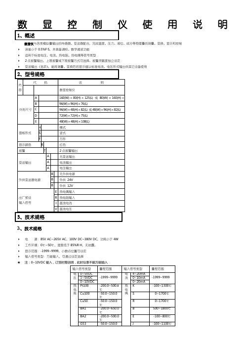
数显控制仪使用说明1、概述数显仪与各类模拟量输出的传感器、变送器配合,完成温度、压力、液位、成分等物理量的测量、变换、显示和控制 误差小于0.5%F .S ,并具备调校、数字滤波功能 适用于标准电压、电流、热电阻、热电偶等信号类型2点报警输出,上限报警或下限报警方式可选择。
报警灵敏度独立设定3、技术规格电 源:85V AC~265V AC ,100V DC~380V DC ,功耗小于4W 工作环境:0℃~50℃,湿度低于85%R .H ,无结露。
显示范围:-1999~9999,小数点位置可设定输入信号类型:万能输入,可通过设定选择★ 注:0~10VDC 输入,订货时需说明,此时仪表不能万能输入℃T -100~400℃.S基本误差:小于0.5%F测量控制周期:0.2秒报警输出:2点继电器输出,触点容量220V AC,3A变送输出光电隔离4mA~20mA,0mA~10mA,0mA~20mA直流电流输出,通过设定选择。
负载能力大于600Ω 1V~5V,0V~5V,0V~10V直流电压输出,需订货时注明输出分辨力:1/1000,误差小于±0.5% F.S★变送输出为选项功能,只有订购选择后,仪表才具有此功能。
外供电源用于给变送器供电,输出值与标称值的误差小于±5%,负载能力大于50mA其它规格,需在订货时注明4、安装与接线为确保安全,接线必须在断电后进行。
(1)仪表与热电阻的接线(2)仪表与热电偶及电流、电压输入的接线(3)仪表与2线制变送器电流信号的接线(4)仪表与3线制、4线制电压、电流变送器的接线A-H规格160×80尺寸的仪表(mm)外形尺寸开孔尺寸接线端子图A-S规格80×160尺寸的仪表(mm)外形尺寸开孔尺寸接线端子图B-F规格96×96尺寸的仪表(mm)外形尺寸开孔尺寸接线端子图C-H规格96×48尺寸的仪表(mm)外形尺寸开孔尺寸接线端子图14 bA-A 变送输出零点修正设定值-500-500 7.315 bAFi 变送输出满度修正设定值0.500-1.500 7.3注:(bout )——输入信号故障时的代用测量值当仪表判断输入信号出故障时,以设置的值作为报警输出和变送输出的输入值。

AS-22乳化剂说明书
性能:这类表面活性剂同时具有非离子和阳离子特性,在各种pH下都可以使用,并表现为非离子(碱性或中性溶液中)或阳离子(在酸性溶液中)特性,具有优良的乳化力、缓蚀性能、防污作用。
乳化剂
用途:在纺织工业中主要用作染色助剂。
也常用在人造丝生产中,不但可以增强纤维丝的强度,As乳化剂,还可保持喷丝孔的清洁,防止污垢的沉积。
在石油炼制工业中使用可以抑制酸气对金属设备的腐蚀,提高设备利用率。
在工业洗涤剂中可以作助剂成分。
1、溶于水及一般有机1溶剂,具有优良的染料分散性、初期缓染性,染料同步上染性等特点。
2、在纺织、印染行业上,用作涤纶纤维的高温高压分散匀染剂,乳化剂op10,适用于快速染色工艺。
3、能够维持染浴在酸性条件下染色,有效避免敏感1染料水解而引起的布面色光偏差。
4、不含溶剂及载体组分,有助于劳动环境的改善,适用于涤纶高温深色染色以及需要暖色调的高温浅色染色。
5、在一般工业上,用作洗涤剂的组分。
SummaryOpcenter™ Execution Electronics (EX EL) software is a digital manufacturing solution for the electronics industry. It is built on an industry-leading manufactur-ing execution system (MES) platform for the electronics, medical device and semiconductor industries. You can use Opcenter EX EL in the electronics value chain for printed circuit board (PCB), mechanical and box-build processes. Opcenter EX EL is part of the Siemens Xcelerator portfolio, the comprehensive and integrated portfolio of software, hardware and services.The solution includes manufacturing operations management (MOM) capabilities such as manufacturing execution, quality management, materials management, planning and scheduling and manufacturing intelligence. This facilitates direct connectivity to machines and production lines.Electronics manufacturers can rapidly provide new product introduction (NPI) and reduce time-to-market to increase their competitive edge in a changing consumer-driven marketplace.Benefits• Improved configuration efficiency for Manufacturing Execution and Intraplant Logistic• Increase inspection efficiency and process security• Reduce total cost of ownership • Cut deployment time and cost • Improve serviceability• Enhance process security and debugging functionalityDIGITAL INDUSTRIES SOFTWAREWhat’s new in Opcenter Execution Electronics 2210Using Opcenter Intra Plant Logistics to improve configuration efficiency for the MES/opcenterOP EX Electronics version 2210 provides an improved integration with Opcenter Intraplant Logistic, technology improvements and new features that increase efficiency in electronic production.CapabilitiesProduction client enhancement – PCB first article inspection includes:• New functionality that will guide operators through the specific components that need to be inspected and recorded when the inspection is complete• Option added to a spec to control if first article will be performed and whether it uses configured NPI instructions or will go through all components• Option to control the frequency that the inspection must be performed• Enhanced the NPI import functionality to allow for importing table/form data as instructions• New NPI import option to control if confirmation is required and the frequency of the confirmationHigh-volume traceability model• New data model for tracking the equipment setup of the product loaded to the equipment• Resources using the new high-volume setup configuration will link each container produced through the resource to the current setup• Reduces the number of database records required to track high-density products or high-volume unit production• Integrated with the standard component issue data modelOpcenter Intra Plant Logistics configuration UI – smart settings• Integrates the Opcenter IPL configuration of factory objects with Opcenter Execution Core• Provides a new UI for managing Opcenter IPL settings of equipment defined in the Opcenter Execution Core factory model• Integrates with the industry solutions configuration for easy installationMaster data management (MDM) upgrade tool for a factory model• Enhances the factory hierarchy page to allow you to import data from Opcenter Execution Electronics internet of things (IoT) MSS• Automatically creates the needed line and equipment objects as resources in Opcenter Execution Core and saves the IPL settings for each factory item importedOpcenter Connect MOM error handling workflow• Implements a new workflow that analyzes the result of a transaction submitted to Opcenter Execute Core and detects failures in the transaction• Automatically saves the original message that resulted in an error as well as the response message containing the error© 2022 Siemens. A list of relevant Siemens trademarks can be found here . Other trademarks belong to their respective owners.84868-D4 10/22 AProduction client user experience (UX) enhancements • Configures the buttons available in the command bar• Controls the sequence, visibility and text displayed for each button • Introduces support for the attached document and record productionevent buttonsREST API enhancements• Extends the configuration tasks in management studio to support: –Enabling and disabling on-demand DLLs–Ability to enter REST API authentication credentials –Ability to stop REST API services• Improves the performance of transaction execution per second by 15 percent • Improves the discoverability using Swagger UI• Delivers enhanced documentation by providing examples in Postman collection formatsSingle sign-on enhancements• Supports the security assertion markup language (SAML) adapter with the user management component (UMC)• Supports the MyID identity provider via UMC Technology enhancements • Chrome 103+• Edge Chromium 103+• Windows Server 2022• Microsoft Access Database Engine 2016• Siemens Web Framework (SWF) 4.6Product release fixes• For the list of product releases (PRs) addressed, please see the release notesSee more details in related documents for Opcenter EX Medical Device and Diagnostics 2210.。
DELLTMTABLE OF CONTENTSOVERVIEWMini Tower Computer (MT) View3-4Desktop Computer (DT) View5-6Small Form Factor Computer (SFF) View7-89-10 Ultra Small Form Factor Computer (USFF) ViewOperating System, Chipset11Processor12Memory13Drives and Removable Storage, System Board Connectors14-15Graphics/Video Controller16External Ports/Connectors16Communications—Network Adapter (NIC), Wireless17Audio and Speakers, Keyboard and Mouse17Security, Service and Support, Software18System Dimensions (Physical)19System Board Connector Maximum Allowable Dimensions19System Level Environmental and Operating Conditions20Power21-22Audio23Communications23-28Graphics/Video Controller29-31Hard Drives32-39 Optical Drive40-42 Media Card Reader 43 BIOS Defaults44 Chassis Enclosure and Ventilation Requirements45 Acoustic Noise Emission Information46-49MINI TOWER COMPUTER (MT) VIEWMT System Board ComponentsDESKTOP COMPUTER (DT) VIEWDT System Board ComponentsSMALL FORM FACTOR COMPUTER (SFF) VIEWSFF System Board ComponentsULTRA SMALL FORM FACTOR COMPUTER (USFF) VIEWUSFF System Board ComponentsMARKETING SYSTEM CONFIGURATIONSNO TE: O ff e rin gs ma y v a ry by c o u nt ry.For mo re i n f o rma ti o n re ga rdi ng the c onfigu ra ti on o f y ou r c om pu ter,c lic k Sta r t>H elp a nd Su ppo r t a nd s elec t th e o p ti on to v i ew i n forma ti o n a bo u t y ou r c ompu t er.OPERATING SYSTEMCHIPSETPROCESSOR1NOTE: Global Standard Products (GSP) are a subset of Dell’s relationship products that are managed for availability and synchro-nized transitions on a worldwide basis. They ensure the same platform is available for purchase globally. This allows customers to reduce the number of configurations managed on a worldwide basis, thereby reducing their costs. They also enable companies to implement global IT standards by locking in specific product configurations worldwide. The following GSP processors identi-fied below will be made available to Dell customers.NOTE: Processor numbers are not a measure of performance. Processor availability subject to change and may vary by region/ country.1 3rd generation CPUs natively support 3 displays with the integrated CPU graphics. Three simultaneous display output requires one DP port witha maximum resolution of 2500x1600 at 60Hz refresh rate and a DP and VGA port with max resolutions of 1920x1200 at 60Hz refresh rates.2 Post launch CPU, available from June for G860; July for G640, i5 3470/S, i5 3570/S, i5 3475S.3 Available at launch, will be replaced in June or July, i5 3470/S replace i5 3450/S; i5 3570/S replace i5 3550/S; G860 replace G850; G640 re-place G630.MEMORYNOTE: Memory modules should be installed in pairs of matched memory size, speed, and technology. If the memory modules are not installed in matched pairs, the computer will continue to operate, but with a slight reduction in performance. The entire memory range is available to 64-bit operating systems.1 To fully utilize 4GB or more of memory requires a 64-bit enabled processor and 64-bit operating system. With 32-bit OS, the total amount of available memory will be less than 4GB. The amount less depends on the actual system configuration.2 1600MHz memory will only perform as 1600MHz memory when 3rd generation CPUs are used. It will perform as 1333MHz memory if 2nd generation i3 2130, i3 2125, i3 2120, G860, G850 CPUs are installed in the system. It will perform as 1066MHz memory if 2nd generation G640,G630 CPUs are installed in the system.DRIVES AND REMOVABLE STORAGE1 For hard drives, GB means 1 billion bytes; actual capacity varies with preloaded material and operating environment and will be less.DRIVES AND REMOVABLE STORAGE1 For hard drives, GB means 1 billion bytes; actual capacity varies with preloaded material and operating environment and will be less.2 Discs burned with this drive may not be compatible with some existing drives and players; using DVD+R media provides maximum compatibility.3 DVD-ROM drives may have write-capable hardware that has been disabled via firmware modifications.4 Dell 19 in 1 Media Card Reader (MCR) is supported via a F5 to F3 bay converter on the MT and DT and requires a slim line optical drive.SYSTEM BOARD CONNECTORSNO TE: S ee De ta i led E n gi n eeri n g Spec i fic a ti o ns fo r ma xi mu m c a rd di men si o n s.1 PCI Slots (Support Standard Rev 2.3)2 PCIe x16 Slots (Support Standard Rev 3.0)3 PCIe x16 (wired x 4), PCIe x1 Slots, miniPCIe (Support Standard Rev 2.0)4 Serial ATA ( 2 ports Support Standard Rev 3.0, the rest of ports Support Standard Rev 2.0)GRAPHICS/VIDEO CONTR OLLERNO TE: M T su p po r ts fu l l h eigh t (FH) c a rds a nd D T a nd S FF su ppo rt s low p rofi l e (LP) c a rd s.EXTERNAL PORTS/CONNE CTORS1This term does not connote an actual operating speed of 1 Gb/sec. For high speed transmission, connection to a Gigabit Ethernet server and network infrastructure is required.COMMUNICATIONS – WIRELESSNO TE : M T su p po r ts fu l l h eigh t (FH) c a rds a nd D T a nd S FF su ppo rt s low p rofi l e (LP) ca rd s.AUDIO AND SPEAKERSKEYBOARD AND MOUSECOMMUNICATIONS - NETWORK ADAPTER (NIC)NO TE : M T su p po r ts fu l l h eigh t (FH) c a rds a nd D T a nd S FF su ppo rt s low p rofi l e (LP) c a rd s.SECURITYSERVICE AND SUPPORTNO TE : Fo r mo r e d eta i l s o n D ell Se rv i c e Pla n s pl ea s e to go to : www.d ell.c om/se rv i c e /se rv i c e_p la nsSOFTWARE1TPM is not available in all countries. Depending on your country regulations, no-TPM system may be available.1For a copy of our guarantees or limited warranties, please write Dell USA L.P., Attn: Warranties, One Dell Way, Round Rock, TX 78682. For more information, visit /warranty.2Service may be provided by third -party. Technician will be dispatched if necessary following phone -based troubleshooting. Subject to parts availability, geographical restrictions and terms of service contract. Service timing dependent upon time of day call placed to Dell. U.S. only.ENVIRONMENTALNO TE : Fo r mo re de ta il s o n Del l E nv i ro nmen ta l fea t u res, p lea s e to go to E nv i ronmen ta l A tt ri bu te s s ec t ion. S ee you r spec i fic re gi o n fo r a v a i la bi li ty.ALL -IN -ONE STANDS AND MOUNTSDETAILED ENGINEERING SPECIFICATIONSSYSTEM DIMENSIONS (P HYSICAL)NO TE: Sy ste m W ei ght a n d Shi ppi n g W e i gh t i s ba sed o n a t y pi c a l c onfi gu ra ti on a nd ma y v a ry ba s ed on P C c o nfigu ra ti o n. A t ypi c a l c o nfigu ra ti o n i nc lu d es: i nt egra ted g ra phi c s, one ha r d dri v e, on e op ti c a l d riv e.SYSTEM BOARD CONNECTOR MAXIMUM ALLOWABLE DIMENSIONSSYSTEM LEVEL ENVIRONMENTAL AND OPERATING CONDITIONSPOWERNO TE: Th ese fo rm fa c to r s u t i li z e a mor e e ffic i ent A c ti v e Pow er Fa c to r Cor re c ti o n (A P FC) pow er su pp l y. Del l rec ommend s o nly Uni v e rs a l Po we r Su ppli es (UPS) b a sed o n Si ne W a v e ou tpu t fo r A P FC PSU s, no t a n a p proxima-ti on o f a Si n e W a v e, Squ a re W a v e, o r qu a si-Squ a re W a v e. I f y ou ha v e qu es ti o ns, p lea s e c onta c t the ma nu fa c-POWERNOTE: These fo rm fac tors utilize a mo re effi cient Active Powe r F acto r C orrec tion (A PFC) po wer su p-ply. De ll reco mmends o nly Uninte rrup tible Po wer Supp lie s (UPS) based on Sine Wave output fo r APFC PSUs, no t an app ro ximation o f a Sine Wave, Sq uare Wave, o r quas i-Square Wave. If you have ques-tions, ple ase contac t the manufac ture to c onfirm the ou tput type.AUDIOINTEGRATED REALTEK ALC269Q HIGH DEFINITION AUDIO MT DT SFF USFF High Definition Stereo support X X X X Number of channels2Number of Bits / Audio resolution16, 20, and 24-bit resolution Sampling rate (recording/playback)Support 44.1K/48K/96K/192 kHz sample rates Signal to Noise Ratio98 dB DAC outputs, 90 dB for ADC inputs Analog Audio X X X X Dolby DigitalTHXDigital out (S/PDIF)Audio Jack ImpedanceMicrophone40K ohm~60K ohmLine-In40K ohm~60K ohmLine-Out100~150 ohmHeadphone1~4 ohmInternal Speaker Power Rating2Watt (peak) / 1Watt (average) COMMUNICATIONS - INTEGRATED LANCOMMUNICATIONS - INTEGRATED LAN (CON.)1 This term does not connote an actual operating speed of 1 Gb/sec. For high speed transmission, connection to a Gigabit Ethernet server and network infrastructure is required.COMMUNICATIONS – NETWORK ADAPTER (NIC)NO TE: M T su p po r ts fu l l h eigh t (FH) c a rds a nd D T a nd S FF su ppo rt s low p rofi l e (LP) c a rd s.1 This term does not connote an actual operating speed of 1 Gb/sec. For high speed transmission, connection to a Gigabit Ethernet server andCOMMUNICATIONS – NETWORK ADAPTER (NIC) (CONT.)1 This term does not connote an actual operating speed of 1 Gb/sec. For high speed transmission, connection to a Gigabit Ethernet server and network infrastructure is required.COMMUNICATIONS – WIRELESSCOMMUNICATIONS – SERIAL PORT PCIE ADD-IN CARDNO TE: M T su p por ts fu l l h eigh t (FH) c a rds a nd D T a nd S FF su ppo rt s low p ro fi l e (LP) c a rd s.GRAPHICS/VIDEO CONTR OLLERNO TE: M T su p po r ts fu l l h eigh t (FH) c a rds a nd D T a nd S FF su ppo rt s low p rofi l e (LP) c a rd s.1 Up to 1.7 GB of system memory may be allocated to support integrated graphics, depending on operating system, system memory size and other factors.2 3rd generation CPUs natively support3 displays with the integrated CPU graphics. Three simultaneous display output requires one DP port with a maximum resolution of 2500x1600 at 60Hz refresh rate and a DP and VGA port with max resolutions of 1920x1200 at 60Hz refresh rates.3 Display output from both onboard and discrete simultaneously if multi display option in BIOS is enabled and Win 7 OS is used.4 For dual graphics card configuration in PCIex16 and PCIex16 (wire as 4), BIOS will disable multi display option automatically and display outputonly from graphics cards.HARD DRIVES11 For hard drives, GB means 1 billion bytes ; actual capacity varies with preloaded material and operating environment and will be less.HARD DRIVES1(CONT.)1For hard drives, GB means 1 billion bytes ; actual capacity varies with preloaded material and operating environment and will be less.HARD DRIVES1(CONT.)1 For hard drives, GB means 1 billion bytes ; actual capacity varies with preloaded material and operating environment and will be less.HARD DRIVES1(CONT.)1 For hard drives, GB means 1 billion bytes ; actual capacity varies with preloaded material and operating environment and will be less.HARD DRIVES1(CONT.)1 For hard drives, GB means 1 billion bytes ; actual capacity varies with preloaded material and operating environment and will be less.HARD DRIVES1(CONT.).1 For hard drives, GB means 1 billion bytes ; actual capacity varies with preloaded material and operating environment and will be less.HARD DRIVES1(CONT.)1 For hard drives, GB means 1 billion bytes ; actual capacity varies with preloaded material and operating environment and will be less.HARD DRIVES1(CONT.)1 For hard drives, GB means 1 billion bytes ; actual capacity varies with preloaded material and operating environment and will be less.OPTICAL DRIVESOPTICAL DRIVES (CONT.)1 Discs burned with this drive may not be compatible with some existing drives and players; using DVD+R media provides maximum compatibility.OPTICAL DRIVES (CONT.)MEDIA CARD READER (MCR)NOTE: Dell 19 in 1 Media Card Reader (MCR) is supported via a F5 to F3 bay converter on the MT and DT and may require a slim line optical drive depending on selectable configuration. MCR is not available on the SFF and USFF chassis.BIOS DEFAULTSCHASSIS ENCLOSURE & VENTILATION REQUIREM ENTSENCLOSURE VENTILATIONIf your enclosure has doors, they need to be of a type that allows at least 30% airflowthrough the enclosure (front and back).ENCLOSURE MINIMUM CLEARANCELeave a 10.2 cm (4 in.) minimum clearance on all vented sides of the computer to permitthe airflow required for proper ventilation.RECOMMENDED ENCLOSUREDo not install your computer in an enclosure that does not allow airflow. This restricts theairflow and impacts your computer’s performance, possibly causing it to overheat.OPEN DESK MINIMUM CLEARANCEIf your computer is installed in a corner, on a desk, or under a desk, leave at least 5.1 cm (2 in.)clearance from the back of the computer to the wall to permit the airflow required for properventilation.REGULATORY COMPLIANCE AND ENVIRONMENTALProduct related conformity assessment and regulatory authorizations including Product Safety, Electromagnetic Compatibility (EMC), Ergonomics, and Communication Devices relevant to this product may be viewed at /regulatory_compliance. The Regulatory Datasheet for this product is located at /regulatory_compliance. Details of Dell's environmental stewardship program to conserve product energy consumption, reduce or eliminate materials for disposal, prolong product life span and provide effective and convenient equipment recovery solutions may be viewed at/environment. Product related conformity assessment, regulatory authorizations, and information encompassing Environmental, Energy Consumption, Noise Emissions, Product Materials Information, Packaging, Batteries, and Recycling relevant to this product may be viewed by clicking the Design for Environment link on the webpage.OPTIPLEX 9010 MTThe Declared Noise Emission in accordance with ISO 9296 for the Dell OptiPlex 9010 MT is as follows:(all values L WAd expressed in bels; 1 bel=10 decibels, re 10-12 Watts)The Declared A-weighted Sound Pressure Level in decibels (re 2x10⁻⁵Pa), at Operator, Bystander, and Desk Side Positions are measured in accordance with ISO 7779 7.6.1, 7.6.2, and C.15.2 and declared in accordance with ISO 9296 for this product is as follows1:1 All tests are conducted according to ISO 7779 and declared according to ISO 9296 except 90% CPU. For this mode, the system CPU was stressed at 90% utilization with no other peripheral device actively seeking. This test mode is not specified in ISO 7779, but was measured using the same microphone distances and measurement techniques defined for the other reported operating modes.OPTIPLEX 9010 DTThe Declared Noise Emission in accordance with ISO 9296 for the Dell OptiPlex 9010 DT is as follows:(all values L WAd expressed in bels; 1 bel=10 decibels, re 10-12 Watts)The Declared A-weighted Sound Pressure Level in decibels (re 2x10⁻⁵Pa), at Operator, Bystander, and Desk Side Positions are measured in accordance with ISO 7779 7.6.1, 7.6.2, and C.15.2 and declared in accordance with ISO 9296 for this product is as follows1:1 All tests are conducted according to ISO 7779 and declared according to ISO 9296 except 90% CPU. For this mode, the system CPU was stressed at 90% utilization with no other peripheral device actively seeking. This test mode is not specified in ISO 7779, but was measured using the same microphone distances and measurement techniques defined for the other reported operating modes.OPTIPLEX 9010 SFFThe Declared Noise Emission in accordance with ISO 9296 for the Dell OptiPlex 9010 SFF is as follows:(all values L WAd expressed in bels; 1 bel=10 decibels, re 10-12 Watts)The Declared A-weighted Sound Pressure Level in decibels (re 2x10⁻⁵Pa), at Operator, Bystander, and Desk Side Positions are measured in accordance with ISO 7779 7.6.1, 7.6.2, and C.15.2 and declared in accordance with ISO 9296 for this product is as follows1:1 All tests are conducted according to ISO 7779 and declared according to ISO 9296 except 90% CPU. For this mode, the system CPU was stressed at 90% utilization with no other peripheral device actively seeking. This test mode is not specified in ISO 7779, but was measured using the same microphone distances and measurement techniques defined for the other reported operating modes.OPTIPLEX 9010 USFFThe Declared Noise Emission in accordance with ISO 9296 for the Dell Optiplex 9010 USFF is as follows:(all values L WAd expressed in bels; 1 bel=10 decibels, re 10-12 Watts)The Declared A-weighted Sound Pressure Level in decibels (re 2x10⁻⁵Pa), at Operator, Bystander, and Desk Side Positions are measured in accordance with ISO 7779 7.6.1, 7.6.2, and C.15.2 and declared in accordance with ISO 9296 for this product is as follows1:1 All tests are conducted according to ISO 7779 and declared according to ISO 9296 except 90% CPU. For this mode, the system CPU was stressed at 90% utilization with no other peripheral device actively seeking. This test mode is not specified in ISO 7779, but was measured using the same microphone distances and measurement techniques defined for the other reported operating modes.。
SINUMERIKSINUMERIK 810D/840D 简明调试指南技术手册 2010Answers for industry.S I N U M E R I K 810D /840D 简明调试指南技术手册 20102前言欢迎使用西门子 810D/840D 产品,相信在此之前,您会收到我们为您精心制作的光盘资料— DOCON CD。
您只需运行其上的 SETUP.EXE 文件,即可将此光盘资料安装在您的计算机上。
DOC ON CD 中的资料包括三部分:用户资料;制造商资料;参考资料,覆盖西门子所有数控产品的内容。
其中,用户资料用于最终用户,包括操作和编程,以及诊断等内容;制造商资料又包括三部分:数控;驱动;PLC,给机床制造。
厂家提供全面的资料,从配置系统到安装启动,以及功能使用说明;参考资料中展示了西门子的数控产品在多种工业领域中的专门应用,还有一些专用软件的应用介绍。
由于我们这本手册的阅读对象为机床制造厂家,因此我们所需参考的资料主要为 DOC ON CD 上的制造商资料,根据机床从设计到生产调试的过程的不同阶段,可分别主要参考相应的资料。
见下表:DOC ON CD 中的资料除按内容划分手册以外,具体在每个章节都针对某个应用详细描述,分为:简述;详述;应用举例;相关参数及接口信号说明;参数信号列表若干小节。
有时您需要了解某个信号的详细应用介绍。
则可以先到 LIST 一书中找到此信号,并由此可查到相关的手册,从而找到具体的章节。
DOC ON CD 中的资料内容浩繁,查找起来比较困难,希望了解了上述内容后,能帮助您更快捷地查阅资料。
目录硬件说明810D/840D1 SINUMERIK1.1 概述1-3 1.2 数控及驱动单元 1-4与 CCU 1-4 1.2.1 810D1.2.2 840D与 NCU 1-5 1.2.3 驱动模块 1-6 1.2.3.1 电源模块 1-6 1.2.3.2 611D数字驱动 1-7单元和 PCU 1-8 1.3 OP1.3.1 OP单元和 MPI 1-8 1.3.2 PCU 1-8 1.3.3 MCP 1-9模块 1-10 1.4 PL C1.5 硬件连接 1-13 1.6 接地1-16 1.6.1 接地电阻 1-16 1.6.2 电柜地线汇总排 1-16 1.6.3 西门子设备的接地 1-16 1.7 将电磁干扰问题(EMC)影响减为最小的措施 1-17 1.7.1 确保电柜中的所有设备接地良好 1-17 1.7.2 控制电缆最好使用屏蔽电缆 1-17 1.7.3 布线1-17 1.8 散热1-18 1.9 防尘1-19 1.10 系统上下电顺序 1-19 1.10.1 电源模块的上下电顺序 1-19的下电顺序 1-201.10.2 PCU502 通电,调试2.1 开机和启动(包括 NCU、PCU、MCP、Drive System) 1-21和 PLC 总清 1-25 2.2 NC总清 1-25 2.2.1 NC2.2.2 PLC总清 1-25调试 1-26 L C2.3 P2.3.1 Step7软件的安装与授权 1-26 2.3.2 设置 PG/PC 接口 1-26 2.3.3 S7程序的结构 1-27 2.3.4 PLC启动 1-28 2.3.5 PLC基本程序 1-292.3.6 若干重要信号 1-30 2.3.7 几点说明 1-30调试 1-31 2.4 NC2.4.1 轴配置1-31 2.4.2 驱动配置 1-32 2.4.3 控制给定值、反馈值的分配 1-34 2.4.4 进给轴机床参数设定 1-34 2.4.5 主轴机床参数设定 1-34 2.5 轴的试运行及其优化 1-35 2.5.1 轴试运行流程图 1-35 2.5.2 主轴试运行流程图 1-362.5.3 轴自动优化自动步骤 1-373 数据备份3.1 系列备份(Series Start-up) 1-40 3.1.1 V.24参数的设定 1-40的数据备份 1-41 3.1.2 PCU20的数据备份 1-41 3.1.3 PCU503.2 分区备份 1-42的数据分区备份 1-42 3.2.1 PCU203.2.1 PCU50.3 的数据分区备份 1-42 3.3 数据的恢复 1-43 3.3.1 PCU20 的数据恢复 1-433.3.2 PCU50.3 的数据恢复 1-434 螺距误差补偿(LEC)4.1 螺补的方法 1-45 4.2 螺补的操作步骤 1-46 4.2.1 在 PCU20 上作螺距补偿 1-464.2.2 在 PCU50.3 上作螺距补偿 1-485 警报5.1 系统警报 1-49 5.2 用户报警 1-49 5.3 报警文本(指 PLC 报警文本) 1-49附录 A SINUMERIK 810D/840D 有关硬件尺寸 1-51附录 B 机床数据简表 1-77附录 C 接口信号简表 1-11923SINUMERIK 810D/840D 硬件说明1.1 概述SINUMERIK 810D/840D 是由数控及驱动单元(CCU 或 NCU ),PCU 及 OP0xx ,PLC 的 I/O 模块三部分组成。
第一章 产品概述 (2)1.1. 功能 (2)1.2. 一般规格 (2)1.3. 尺寸 (3)1.4. 安装 (3)1.5. 组成部分 (4)1.5.1. LCD (4)1.5.2. 按键 (4)1.5.2.1. 按键基本功能 (4)1.5.2.2. 按键自定义局部按钮功能 (5)1.5.2.3. 按键自定义全局按钮功能 (5)1.5.2.4. 按键功能的优先顺序 (5)1.5.3. 通讯口 (5)第二章 编辑软件 (7)2.1. 基本概述 (7)2.2. 关于工程和画面 (7)2.3. 画面内容 (7)2.4. OP10PC的使用流程 (7)2.5. 编辑用户画面 (7)2.5.1. 创建工程 (7)2.5.2. 制作基本画面 (9)2.5.3. 设置OP10 (10)2.5.4. OP10控件 (11)2.5.5. 静态文本 (12)2.5.6. 动态文本 (13)2.5.7. 功能键 (15)2.5.8. 数据显示 (18)2.5.9. 数据设定 (20)2.5.10. 指示灯 (22)2.5.11. 功能键(开关量控制) (26)2.5.12. 柱状图 (27)2.5.13. 曲线图 (29)2.5.14. 报警列表 (30)2.6. 保存工程 (33)2.7. 下载画面 (33)第三章 操作方法 (34)3.1. 联机通讯 (34)3.2. 切换画面 (34)3.3. 系统口令 (34)3.4. 修改数据 (38)第四章通信 (40)4.1. 通讯口 (40)4.2. 通信连接 (40)4.2.1. 下载用户程序 (40)4.2.2. 与TP03 PG口以RS-422方式连接 (41)4.2.3. 与TP03 485口连接 (41)4.2.4. 与EV300 连接 (41)4.2.5. 与SV300 连接 (42)第一章 产品概述1.1.功能OP10是一个小型的人机界面,主要与各类PLC(或带通信口的智能控制器)配合使用,以文字或指示灯等形式监视、修改PLC内部寄存器或继电器的数值及状态,从而使操作人员能够自如地控制机器设备。
OP10可编程文本显示器有以下特点:通过编辑软件OP10PC在计算机上制作画面,自由输入汉字及设定PLC地址,使用串口通讯下载画面通讯协议和画面数据一同下载到显示器,无须PLC编写通讯程序目前支持modbus rtu协议具有密码功能,密码可以有6个密码,3个等级。
具有报警列表功能,逐行实时显示当前报警信息。
24个按键可被定义成功能键,有数值输入小键盘,操作简单,可替代部分控制柜上机械按键自由选择通讯方式,RS232/RS422/RS485任选,OP10支持一个工程中不同画面使用不同的通讯口通讯。
1.2.一般规格项目规格备注电源 DC24V-15%~+10%尺寸运行周温0℃~55℃高度不高于海拔2000m相对湿度 10%~95%,非结露环境污染级别污染等级2 IEC61131-3-3.45.2振动5≤f<9 Hz 1.75mm幅度连续振动9≤f≤150Hz 0.5g连续振动机械运行状态冲击3向垂直正交方向15g,11ms温度 -40℃~70℃运输及储存条件高度不高于海拔3000m自由落体带产品包装 0.3m 带运输包装 1m1.3.尺寸1.4.安装1.5.组成部分1.5.1.LCD4.3” 单色,192*64点。
黄绿背光。
1.5.2.按键OP10的正面除液晶显示窗之外,还有24个薄膜开关(机械)按键,触摸手感好、使用寿命长、安全可靠。
所有的24个按键除了具备基本功能外,还能被设定成局部按钮功能,全局按钮功能。
OP101.5.2.1.按键基本功能功能按键的基本功能如下表:按键 基本功能[ESC] 不论显示器处于显示任何画面,一旦按此键,返回系统初始画面。
系统初始画面由用户设计画面时指定(缺省值为1号画面,0号画面禁用)。
一般将系统初始画面设置成主菜单或使用频度最高的画面。
[ALM] 一旦按此键,返回系统自动切换到定义的报警信息画面,也可定义为功能按键使用。
(如果工程中没有用到报警列表系统功能无效).[←] 修改寄存器数据时,左移被修改的数据位,即闪烁显示数字左移一位.[→] 修改寄存器数据时,右移被修改的数据位,即闪烁显示数字右移一位.[↑] 将画面翻转到前页,前页画面号由用户在画面属性中指定(缺省值为当前画面号-1)如果在数据设定状态,被修改的数字位加1,递减范围:9—>0—>9(10进制)F->0->F(16进制)[↓] 将画面翻转到次页,次页画面号由用户在画面属性中指定(缺省值为当前画面号+1)如果在数据设定状态,被修改的数字位减1,递减范围:9—>0—>9(10进制)F->0->F(16进制)[SET] 按此键开始修改寄存器数值,当前正在被修改的寄存器窗反色显示,其中被修改的位数闪烁显示。
如果当前画面没有寄存器设定窗部件,则执行一次空操作。
在按[ENT]键之前再按一次[SET]键,则当前修改操作被取消,并继续修改下一个数据寄存器。
注意:SET键设定寄存器具有最高优先级,不能被用户功能键定义所屏蔽。
[ENT] 用户使用了加密功能的情况下,按此键弹出口令设定画面。
在寄存器设定状态下,将修改后的数据写入寄存器,并继续修改下一个数据寄存器。
当前画面的最后一个寄存器被修改后,退出修改寄存器状态。
0-9 1. 可以作为按钮控件使用,设置线圈状态,跳转画面或者设定寄存器值。
1. 在寄存器输入状态时作为数值输入用。
F1-F4 全局控制按钮。
普通功能有切换换面,改变线圈状态,改变IO状态,修改寄存器等。
高级功能有目标控制器的开关机等。
1.5.2.2.按键自定义局部按钮功能所有24个按键都能被用户定义成特定功能。
如设定线圈、画面跳转,设定寄存器数值,递增,递减等功能。
局部按钮可以在当前画面设定,仅在当前画面显示时才起作用。
1.5.2.3.按键自定义全局按钮功能所有24个按键都能被用户定义成特定功能。
如设定线圈、画面跳转,设定寄存器数值,递增,递减等功能。
全局按钮可以在工具菜单下设定定,不论显示什么画面都起作用。
1.5.2.4.按键功能的优先顺序如果一个按钮被自定义成特殊功能后,就具有了多种功能,但只有优先级最高的功能会被执行。
其它功能会被忽略。
除了[SET],[ALM]键,优先顺序由高到低为:局部按钮Æ全局按钮Æ基本功能[SET],[ALM]键,优先顺序由高到低为: 基本功能Æ局部按钮Æ全局按钮[SET]键在执行设定寄存器这一基本功能时,具有最高的优先级。
因此,如果画面上存在寄存器设定功能,请不要再定义[SET]键用于其它功能。
按[SET]进入设定 功能后,所有自定义的其它功能键都不起作用,直到结束设定功能,才恢复自定义功能。
[ALM]键在有报警列表的情况下,具有最高的优先级。
因此,如有添加报警列表的定功能,请不要再定义[ALM]键用于其它功能。
按[ALM]键进入报警列表后,自定义的局部按钮就不起作用了,[↑],[↓],[ESC]恢复成基本功能,其它的还保留原定义的全局按钮功能。
OP10显示屏自带LED背景光灯,只要有按键操作,背景光打开。
用户也可设置背光常亮。
1.5.3.通讯口OP10 有两个通信口,COM1和RS485。
COM1 用于下载用户程序,并提供RS422的接口;RS485则提供了RS485的接口。
COM1:引脚号定义说明422 发送正信号1 TX+232 接收信号2 RX232 发送信号3 TX4 NC5 GND6 TX-7 VCC8 RX-9 RX+RS485:第二章 编辑软件2.1.基本概述OP10PC软件是可编程文本显示器OP10专用的组态软件,运行于WINDOWS 98/2000/xp之下。
该软件使用方便,能直接输入中英文字符。
2.2.关于工程和画面用户针对某项目制作的画面都保存在一个工程之中,工程的基本要素是画面。
每一幅画面完成一些特定功能,通过设计可以实现不同画面之间自由跳转。
由所有画面组成的集合,就是设计人员开发完成的应用工程文件。
2.3.画面内容打开工程后,用户就可以新建或打开画面。
每幅画面都可以放置文字(中英文)、指示灯、开关、数据显示设定窗、跳转键等元素。
每幅画面之间可实现自由跳转,操作者可完成数据监视、参数设定、开关控制、报警列表监视,PLC之间寄存器数据传递等操作。
2.4.OP10PC的使用流程OP10PC的基本使用流程如下:2.5.编辑用户画面2.5.1.创建工程运行OP10PC软件,效果如下编辑器的中央是画面编辑区。
在显示区域均匀放置白色网点,网点上下左右之间的距离为16点间距,整个画面为192×64点阵。
设计者放置或移动部件时,参照临近网点的位置,便于将部品对齐。
如果需要得到任意位置的点,可以直接调节部件的X,Y坐标值。
以下是工具条中所有按键及其功能说明:按键 功能创建一个新工程打开一个已经保存的工程保存正在编辑的工程下载组态好的工程数据到OP10读取OP10内的工程数据编译工程,显示工程信息新建画面,其功能和画面指示窗中的[新建]按键相同编辑画面属性将一幅画面拷贝成另一幅画面删除当前画面指定系统初始画面,显示器工作时, 按[ESC]键即直接返回此画面。
一般此画面为主菜单或使用频度最高的画面;设置系统口令;设置交互控制寄存器定义号登录报警列表信息,每条报警信息对应一个中间继电器按键或击活[文件]—>[新建工程]命令,屏幕中弹出PLC机型选择对话窗:用户选择正确的机型。
然后点击端口后的“设置”按钮,设置通讯参数。
在这个窗口选择正确的波特率、数据位、停止位和校验位以及通讯口。
OP10支持两个通讯口连接不同的PLC和变频器进行通讯,通讯格式可以不同.根据显示器通讯对象,选择PLC机型。
OP10PC下载画面时,将指定的PLC通讯协议和画面数据一同传送给OP10显示器,显示器工作时,通过此协议和PLC通讯。
2.5.2.制作基本画面下例以TP03 PLC为对象进行说明。
首先进入系统初始画面(缺省为1号画面)的编辑状态。
界面的右下边是当前编辑画面(1号画面)的属性,每幅画都有属性,包括四项内容:画面描述:描述画面的性质,便于设计者管理,只有提示作用,亦可不用填写。
举例输入“主菜单”;按[∧]键至画面号:该数值为按[∧]键,显示器跳转至画面号;按[∨]键至画面号:该数值为按[∨]键,显示器跳转至画面号。
通讯口选择OP10支持每个画面选择不同的通讯口。
显示器运行时,按[ESC]键、[∧]键或[∨]键是最简捷的切换画面方法。
除此之外,通过设置功能键也能实现画面跳转。
注:如果当前画面的[∧]键或[∨]键设定成功能键,则画面属性中跳转画面参数不起作用。