JGTCOT430调速型磁力偶合器说明书
- 格式:doc
- 大小:1.48 MB
- 文档页数:8

限矩形磁力耦合器-概述说明以及解释1.引言1.1 概述磁力耦合器是一种能够传输功率和扭矩的非接触式传动装置,它通过磁场的作用在两个磁性元件之间传递动力,避免了机械传动中存在的摩擦和磨损问题。
在工业生产和科研领域,磁力耦合器被广泛应用于需要隔离和传输动力的场合。
而限矩形磁力耦合器是一种新型的磁力耦合器设计,它在传统磁力耦合器的基础上进行了改进,通过限制磁场的形状和大小来实现对扭矩的精确控制,从而提高了其在工程应用中的适用性和可靠性。
本文将对限矩形磁力耦合器的原理、设计和应用进行详细介绍,以期为相关领域的研究和工程实践提供参考和借鉴。
1.2 文章结构文章结构部分应包括对整篇文章的总体布局和每个部分的摘要。
这可以帮助读者更好地理解文章的结构和内容安排。
在文章结构部分,我们可以简要介绍本文的组织架构,包括引言、正文和结论部分,并提及每个部分的内容概要。
例如:引言部分将对磁力耦合器的基本概念进行介绍,说明本文的目的和结构;正文部分将详细解释磁力耦合器的原理、限矩形磁力耦合器的设计及其应用与优势;结论部分将对全文进行总结,并展望磁力耦合器在未来的发展前景。
这样,读者在开篇就能清晰地了解本文的整体结构和各部分的内容,有助于他们更好地理解和阅读文章。
1.3 目的本文旨在介绍限矩形磁力耦合器的设计原理、结构特点以及其在工程应用中的优势。
通过深入解析磁力耦合器的工作原理,探讨限矩形磁力耦合器的设计方法和应用范围,为工程技术人员提供相关领域的参考和借鉴。
同时,通过本文的阐述,还可以为限矩形磁力耦合器在工程领域的发展提供一定的理论支持和实际应用价值。
2.正文2.1 磁力耦合器原理:磁力耦合器是一种利用磁场传递能量和扭矩的装置,通常由两个磁性元件组成,分别位于两个不同的系统中。
这种耦合器通常用于在需要隔离或保护的环境中传输能量,例如在化工、医疗和食品加工行业中。
磁力耦合器的工作原理基于磁场的相互作用。
当一个磁性元件转动时,它会改变磁场的分布,从而影响另一个磁性元件上的感应电流,最终传递扭矩和能量。

JJCC磁性金属物测定仪使用说明书一、JJCC磁性金属物测定仪概述:JJCC磁性金属物测定仪是依据国家标准GB/T5509-2008《粮油检测粉类磁性金属物测定》研制的检测粉类粮食中磁性金属物含量的专用仪器。
适用于面粉、大米粉、糯米粉、玉米粉以及各种谷物营养粉等商品粉类粮食加工、粮食储运、购销、科研、质量监督等需对粉类磁性金属物的含量进行测定的部门。
托普云农JJCC磁性金属物测定仪采用上下台式结构,双头电磁铁,检测速度比传统的单头电磁铁快一倍,该仪器结构例题、运转平稳、性能稳定可靠、操作简单方便。
二、JJCC磁性金属物测定仪技术参数:1.电源:AC(220±22)V、50Hz、1A2.电机(双刮刀)转速:50 r/min3.电磁铁吸力:≥40 kg5.试样量:≤1 kg6.回收率:≥95 %7.外形尺寸:255×275×385 mm8.重量:12 kg磁性分离板技术规格:磁感应强度:不少于120mT强磁区域尺寸:130mm×130mm分离板尺寸:210mm×210mm×6mm三、JJCC磁性金属物测定仪操作方法:1、取样:试样的扦样和分样按GB5491执行。
2、仪器分离:从分取的平均样品中称试样(m)1kg,精确到1g。
倒入测试仪上部的容器内,接通电源(电源开关在仪器的后下部),接通磁开关,再按电机运转开关,调节流量控制钮(面板上流量控制钮左右各一个,顺时针旋转增加,反之减小),控制试样流量在250g/min左右,使试样匀速通过淌样板进入储粉箱内。
待试样流完后,按下电机运转开关(电机停转),用洗耳球将残留在淌样板上的试样吹入储粉箱,然后用干净的白纸(约200mm×300mm)接在测定仪淌样板下面,关闭通磁开关,立即用毛刷刷净吸附在淌样板上的磁性金属物(含有少量试样),并收集到放置的白纸上。
3、分离板分离:将收集有磁性金属物和残留试样混合物的纸放在事先准备好的分离板上,用手拉住纸的两端,沿分离板前后左右移动,使磁性金属物与分离板充分接触并集中在一处,然后用洗耳球轻轻吹弃纸上的残留试样,最后将纸上的磁性金属物收集到称量纸(硫酸纸或不易吸水的纸)上。

浅谈磁力耦合器调速作者:许新军李俊卿来源:《中国科技博览》2014年第05期[摘要] 国内的电机的调速方式一般都是依靠变频器来实现的,变频器的工作环境要求很高,参数设置复杂,维修困难给变频器的用户带来了很多的不便利。
变频调速技术依然存在一些迫切需要解决的问题。
为增强调速的稳定性、可靠性、安全性,同时降低运营成本,提出磁力耦合器应用到电动机调速中去,实现电动机调速平滑过渡,进而达到优化配置整个电力系统,对其进行深入研究具有重要的理论意义。
本文从论述了磁力耦合器来实现调速,分别与变频器经济性、稳定性、可靠性进行对比,从而选择最佳的调速方式。
[关键词] 变频器磁力耦合器经济性可靠性中图分类号TM32 文献标识码A 文章首先,从经济性阐述随着自动化程度越来越高,变频器被广大的领域应用。
由于变频器安装环境的需求,所以使用的环境也带来了很大的限制。
变频器与设备之间电缆不能超过50米,很容易形成尖峰电压,造成设备的损坏并且对电网也有很大的污染。
通常消除变频的的尖峰电压是通过进线滤波电容、出口电抗器、尖峰电压吸收器来完成的。
以笔者的企业为例,锅炉引风机引用的高压变频器来调节锅炉引风机风量的大小的,由于厂区的地理环境限制,硫铵与灰库和变频器配电室距离不到50米。
硫铵的腐蚀性气体和粉尘对模块的电路板造成很大的损坏,再加上空水冷来降低IGBT的温度根本满足不了,造成了几次锅炉停车的事故,直接经济损失达到数千万。
为了改善变频器的温度和粉尘污染问题,不得不投入了空调和正压通风装置。
从上述的附属设施配电室、空调、正通风装置等,对用户又是一个不小的投资。
磁力耦合器是一个纯机械产品,没有工作环境的限制。
更适合于易燃易爆的环境,由于磁力耦合器是通过磁场传递扭转的传动装置。
电动机与负载转轴之间没有任何机械连接。
当电机转动时,导磁转子上的铜质导磁盘钻有稀土材料制成的永磁转子所产生的强磁场中切割磁力线,从而在到磁盘中产生涡流,强大的涡电流在导磁转子与永磁转子的相对运动。

YOT CGP调速型液力偶合器使用说明书大连创思福液力偶合器成套设备有限公司二零零三年六月YOT CGP调速型液力偶合器安装、使用、维修说明本说明书将为您安装、使用、维修保养YOT CGP调速型液力偶合器提供指导和方便,请您务必仔细阅读。
目录1. 概述-------------------------------------------------------------------------12. 主要技术参数-------------------------------------------------------------13. 主要结构特点-------------------------------------------------------------14. 工作原理-------------------------------------------------------------------25. 液力偶合器的基础、吊运和安装------------------------------------36. 注油-------------------------------------------------------------------------57. 操作与使用----------------------------------------------------------------58. 液力偶合器的维修与保养--------------------------------------------- 89. 可能的故障及排除方法------------------------------------------------ 910.轴承明细表----------------------------------------------------------------911.密封件明细表-------------------------------------------------------------912.备件的订购方法----------------------------------------------------------91.概述YOT CGP调速型液力偶合器一般安装在三相异步电机和工作机之间,它可在电机输入转速不变的条件下,以电动执行机构带动勺管改变其工作腔(泵轮与涡轮间)充液量从而对其输出转速(即工作机转速)进行无级调节,调速过程柔和平滑,输出转速稳定,动力传递可靠,广泛用于风机、水泵、皮带机等负载的工况调节。
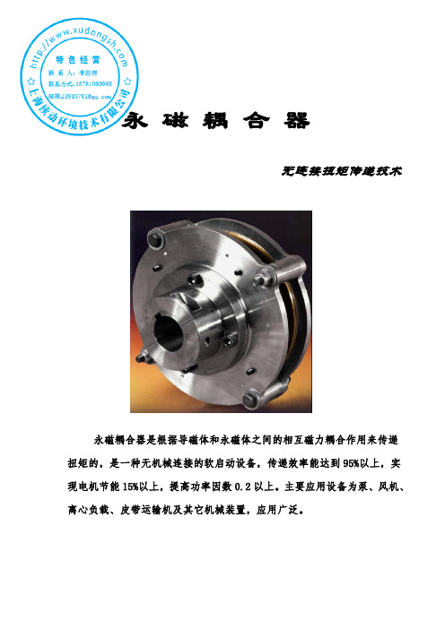
永磁耦合器无连接扭矩传递技术永磁耦合器是根据导磁体和永磁体之间的相互磁力耦合作用来传递扭矩的,是一种无机械连接的软启动设备,传递效率能达到95%以上,实现电机节能15%以上,提高功率因数0.2以上。
主要应用设备为泵、风机、离心负载、皮带运输机及其它机械装置,应用广泛。
永磁耦合器一、产品工作原理永磁耦合器是通过切割磁力线来传递转矩的,是一种创新型的传动链接产品。
永磁耦合器属于耦合传动的一种,可以实现非接触性的动力传递。
它是由两个独立的,没有任何接触的转体组成,这两个转体之间有一定的空隙。
其中导体转子(棕色)与电机输出端联接,永磁转子(紫色)与负载输入端联接。
电机转动过程中即导体转子与永磁转子产生相对运动,交变磁场通过气隙在导体转子铜盘上产生涡流,同时涡流产生感应磁场与永磁场相互作用,由于负载转矩作用,被动永磁转子仍处于静止,当主动导体转子转过一个角度后,其和永磁转子之间存在一定的转差角,从而使得静止的平衡状态被打破,主动端所转过的角度的大小取决于负载转矩的大小,此时从动端会受到电磁力矩的作用,电磁转矩随着主动端与从动端的转差角的增加而增大;当电磁转矩超过负载转矩时,从动端开始转动。
此后,在电动机的驱动下,主动端将与从动端保持一定的转差角度同步运行。
从而带动永磁转子沿着与铜转子相同的方向旋转,结果在负载侧输出轴上产生转矩,带动负载做旋转运动。
来实现动力的无接触传递。
实现电机与负载之间的扭矩传递。
永磁耦合器所能承受的最大负载转矩由静转矩特性的峰值转矩决定,当负载转矩值超过该峰值大小时,将会产生失步现象。
(附永磁耦合器原理图)。
原理图原理图上:棕色--代表导体转子紫色--代表永磁转子导体--为铜盘说明:此图用于对工作原理解释,并非实物结构图。
永磁耦合器效果图图1 图2 图3效果图上:灰色--代表导体转子橄榄色--代表永磁转子铁红色--代表铜盘※该永磁耦合器是由导体转子(铜导体)、永磁体转子组成,两者无连接。

调速型液力偶合器YOT系列调速型液力偶合器一、概述YOT系列调速型液力偶合器是以液体为介质传递功率并实现无级调速的液体联轴装置。
调速型液力偶合器主要用于各种风机和水泵等设备上,经国内外用户使用普遍反映节能效果显著。
调速型液力偶合器与其它机械联轴装置相比具有以下特点:1.调速型液力偶合器可以在原动机转速不变的情况下连续无级调节被驱动机械的转速,当与离心式风机、水泵相配时,其调速范围为1 ~1/4,当与活塞式机械相配时,其调速范围为1 ~1/3;2.调速型液力偶合器能使电机空载启动,不必选择过大功率余量能力的电动机等原动机,并且可以减少电网负荷的波动;3.调速型液力偶合器具有过载保护的性能;4.隔离振动,减缓冲击;5.调速型液力偶合器的传动部件间无直接机械接触、使用寿命长;6.调速型液力偶合器在额定负载下有较高的传动效率;7.调速型液力偶合器具有液力控制调速装置和两个半轴,易于实现远距离自动操作;调速型液力偶合器具有结构合理,性能先进,可靠性高,能满足冶金、建材、发电等行业长期连续运转工况要求。
二、调速型液力偶合器主机及配套件主要技术参数1、液力偶合器的型号注解:2、调速型液力偶合器技术参数(参看表1、表2、表3)表1 YOT系列调速液力偶合器主要技术参数:型号转速(转/分)功率(千瓦)调速范围滑差调速时间(秒)工作油牌号装油量约(升)重量(公斤)YOT45 /30 2970 350-80025%-97%≤3%<3022°透平油250130YOT50 /30 2970 600-1600 同上同上同上同上300140YOT56 /15 1470 200-400同上同上同上同上3001500 970 50-100YOT63 /15 1470 380-620同上同上同上同上3001800 970 90-220730 50-80YOT71 /15 1470 500-1100 同上同上同上同上380230YOT71 /10 970 200-380同上同上同上同上3802300 730 70-140YOT80 /15 1470 700-1600 同上同上同上同上380250YOT80 /10 970 260-580同上同上同上同上3802500 730 130-250YOT90 /10 970 500-1100同上同上同上同上4303200 730 200-450YOT10 0/10 970 800-1800同上同上同上同上4303500 730 350-760YOT系列调速型液力偶合器外形参数标注示意图(即表2的标注参数示意)表3 YOT系列调速型液力偶合器配用部件主要技术参数:调速型液力偶合器配用换热器主要技术参数配用滤油器参数配用电动执行器技术参数型公外型尺寸型号通最大型号均输入信说明:1、换热器换热面积应由用户按使用工程选配,本公司也可代为选配价格另计。
磁力耦合器说明书磁力耦合器说明书,磁力耦合器是目前使用范围非常普遍的元件,广泛的使用在各种通用机械上。
目前,我国的磁力耦合器主要有两种结构,即平面磁力传动耦合器和同轴磁力传动耦合器。
磁体以轴向充磁,耦合磁极成轴向配置的叫平面磁力传动耦合器。
磁体以径向充磁,耦合磁极成径向配置的叫同轴磁力传动耦合器。
不管是哪种磁力耦合器其工作的原理都是一样的。
本文就为大家详细的阐述一下磁力耦合器的工作原理。
一般磁力传动耦合器由外磁体、内磁体和隔离罩部分组成的。
内、外磁体均由沿径向磁化且充磁方向相反的永磁体组成,并以不同的极性沿圆周方向交替排列,固定在低碳钢钢圈上,从而形成磁断路连体。
隔离罩采用的是非铁素体的高电阻材料制造,从而是非磁性的,最常见都是用奥氏体不锈钢。
在静止状态时,外磁体的N极(S极)与内磁体的S极(N极)相互吸引,从而并成直线,此时的转矩为零。
当外磁体在动力机的带动下旋转时,刚开始内磁体由于摩擦力及被传动件阻力的作用,仍处于静止状态。
这时外磁体相对内磁体开始偏移一定的角度,由于这个角度的存在,外磁体的N极(S极)对内磁体的S极(N极)有一个拉动作用。
同时外磁体的N极(S极)对内磁体的前一个N极(S极)有一个推动作用,使内磁体有一个跟着旋转的趋势。
这就是磁力联轴器的推拉磁路工作原理。
安徽沃弗电力科技有限公司是一家集科研、设计、生产、销售服务为一体的高新技术企业,凭借在永磁传动领域的专业水平和成熟的技术,在工业领域迅速崛起。
安徽沃弗电力科技有限公司奉行“进取、求实、严谨、团结”的方针,不断开拓创新,以技术为核心,视质量为生命,奉用户为上帝,竭诚为您提供性价比最高的永磁产品,高质量的工程改造设计及无微不至的售后服务。
1/28Doc. no. CY*S-OM0078P Magnetically Coupled Rodless Cylinder(Slider Type: Slide Bearing)Series CY1S-Z2/28Safety Instructions ・・・P3~P41. Mounting・・・P5~P71-1) Surface for mounting1-2) Mounting the cylinder1-3) Minimum necessary space for the installation of the cylinder2. Operation・・・P7~P83. Functions・・・P8~P113-1) Piping selection3-2) Stopper type3-3) Auto switches3-3-1) Applicable auto switches3-3-2) Mounting of auto switch3-3-3) Mounting and removal of the switch rail.3-3-4) Groove for the switch rail lead wire.3-3-5) Switch response at intermediate positions of the stroke.4. Model selection・・・P12~P20Selection Flow ChartCheck allowable load mass by thrustCheck allowable load mass by strokeConsider load factor on guidesCalculation method to determine the center of gravitywhen several loads are mounted on the cylinderCalculation of Guide Load Factor (Calculation example1: Mounting on horizontal wall)Calculation of Guide Load Factor (Calculation example2: Vertical mounting)5. Vertical operation and intermediate stop ・・・P225-1) Vertical operation5-2) Intermediate stop6. Stopper・・・P236-1) Stroke setting6-2) Caution when replacing shock absorber7. Cautions for disassembly and maintenance・・・P23~P248. Made to order product・・・P259. Internal construction and component・・・P26~P27Safety InstructionsThese safety instructions are intended to prevent hazardous situations and/or equipment damage.These instructions indicate the level of potential hazard with the labels of “Caution,” “Warning” or “Danger.” They are all important notes for safety and must be followed in addition to International Standards (ISO/IEC)*1)*1) ISO 4414: Pneumatic fluid power -- General rules relating to systems. , and other safety regulations.ISO 4413: Hydraulic fluid power -- General rules relating to systems.IEC 60204-1: Safety of machinery -- Electrical equipment of machines .(Part 1: General requirements)ISO 10218-1992: Manipulating industrial robots -Safety. etc.Caution Caution indicates a hazard with a low level of risk which, if not avoided, could resultin minor or moderate injury.Warning Warning indicates a hazard with a medium level of risk which, if not avoided, could result in death or serious injury.DangerDanger indicates a hazard with a high level of risk which, if not avoided, will resultin death or serious injury.Warning 1. The compatibility of the product is the responsibility of the person who designs the equipment ordecides its specifications.Since the product specified here is used under various operating conditions, its compatibility with specific equipment must be decided by the person who designs the equipment or decides its specifications based on necessary analysis and test results.The expected performance and safety assurance of the equipment will be the responsibility of the person who has determined its compatibility with the product.This person should also continuously review all specifications of the product referring to its latest catalog information, with a view to giving due consideration to any possibility of equipment failure when configuring the equipment.2. Only personnel with appropriate training should operate machinery and equipment.The product specified here may become unsafe if handled incorrectly.The assembly, operation and maintenance of machines or equipment including our products must be performed by an operator who is appropriately trained and experienced.3. Do not service or attempt to remove product and machinery/equipment until safety is confirmed.1.The inspection and maintenance of machinery/equipment should only be performed after measures to prevent falling or runaway of the driven objects have been confirmed.2.When the product is to be removed, confirm that the safety measures as mentioned above are implemented and the power from any appropriate source is cut, and read and understand the specific product precautions of all relevant products carefully.3. Before machinery/equipment is restarted, take measures to prevent unexpected operation and malfunction.4. Contact SMC beforehand and take special consideration of safety measures if the product is to be used in any of the following conditions.1. Conditions and environments outside of the given specifications, or use outdoors or in a place exposed to direct sunlight.2. Installation on equipment in conjunction with atomic energy, railways, air navigation, space, shipping, vehicles, military, medical treatment, combustion and recreation, or equipment in contact with food and beverages, emergency stop circuits, clutch and brake circuits in press applications, safety equipment or other applications unsuitable for the standard specifications described in the product catalog.3. An application which could have negative effects on people, property, or animals requiring special safety analysis.e in an interlock circuit, which requires the provision of double interlock for possible failure by using a mechanical protective function, and periodical checks to confirm proper operation.3/284/28Safety InstructionsCaution1.The product is provided for use in manufacturing industries.The product herein described is basically provided for peaceful use in manufacturing industries.If considering using the product in other industries, consult SMC beforehand and exchange specifications or a contract if necessary.If anything is unclear, contact your nearest sales branch.Limited warranty and Disclaimer/Compliance RequirementsThe product used is subject to the following “Limited warranty and Disclaimer” and “Compliance Requirements”.Read and accept them before using the product.Limited warranty and Disclaimer1.The warranty period of the product is 1 year in service or 1.5 years after the product is delivered, whichever is first.∗2)Also, the product may have specified durability, running distance or replacement parts. Please consult your nearest sales branch.2. For any failure or damage reported within the warranty period which is clearly our responsibility,a replacement product or necessary parts will be provided.This limited warranty applies only to our product independently, and not to any other damage incurred due to the failure of the product.3. Prior to using SMC products, please read and understand the warranty terms and disclaimers noted in the specified catalog for the particular products.∗2) Vacuum pads are excluded from this 1 year warranty.A vacuum pad is a consumable part, so it is warranted for a year after it is delivered.Also, even within the warranty period, the wear of a product due to the use of the vacuumpad or failure due to the deterioration of rubber material are not covered by the limitedwarranty.Compliance Requirements1. The use of SMC products with production equipment for the manufacture of weapons of massdestruction (WMD) or any other weapon is strictly prohibited.2. The exports of SMC products or technology from one country to another are governed by therelevant security laws and regulations of the countries involved in the transaction. Prior to the shipment of a SMC product to another country, assure that all local rules governing that export are known and followed.1-1)Surface for mounting①Mount the cylinder with the surface which flatness is 0.2mm or less.When the flatness is more than 0.2mm, two guide shaft will be twisted, increasingsliding resistance, shortening the product life.②If the required flatness is not available, make adjustment of the gap using a shim.Make adjustment so that the slide block moves smoothly at the minimum operatingpressure [0.18Mpa] for full stroke.③Make sure that there are no foreign matters including debris on the mountingsurface before mounting the cylinder.If the cylinder is fixed with debris in between the cylinder and the mounting surface, the guide shaft may be twisted and poor performance or short life can result.④It is recommended to configure the mounting surface for the cylinder withthe same material of the cylinder.If the material of the cylinder and the mounting surface is different, the flatness of the mating surface will be insufficient.When the materials are different, adjust the flatness at 0.2mm or less using a shim.1-2)Mounting the cylinder①Mount the cylinder using the plate on both ends.(Do not mount the cylinder using the slide block (Fig.2).Otherwise, excessive moment will be applied to the bushing at the stroke,wearing the bushing in early stage of life.Fig.1 Cylinder mounting surfaceMounting surface of different materialsMounting surface with the samematerial with high rigidityFig.2 Do not mount the cylinder using the slide blockPlateSlide block②Cylinder has to be fixed by screws from the top surface of the plate (surface with countersunk).If the cylinder needs to be fixed by screws from the bottom, please use made-to-order product [-X2423].*) -X2423: Mounting surface tapped hole type (Refer to Page 24, Fig.13, Table 14)1-3)Minimum necessary space for the installation of the cylinder Keep adequate space in operating directions of the bumper bolt, shock absorber and thefitting for ease of mounting and replacement. Table 1 shows the minimum necessary space. Keep more space than is required.Fig.3 Cylinder mounting method (Standard product)Fig.4 Minimum necessary spaceX2423 (Screw type for the mounting① Do not put your hand between the plate and the slide block during the cylinder operation. It is very dangerous.② Do not apply the load more than allowable value of the cylinder.It will cause malfunction.③ Check the supply pressure, and the kinetic energy that the cylinder generates,When performing an intermediate stop. Fine stroke end adjustment is considered as an intermediate stop, so the considerations for an intermediate stop must be observed. [When stopping the external slider in an intermediate position with external stopper] If the allowable pressure values are exceeded, the stopper position might be displaced or the external slider may become detachedfrom the magnetic coupling and drop.[When stopping the external slider in an intermediate position in a pneumatic circuit] If the external kinetic energy of the load on the slider exceeds the allowable values, the stopper position might be displaced or the external slider may become detached from the magnetic coupling and drop.Note) The dimensions above show the minimum necessary space for the replacement ofthe shock absorber and bumper bolt. (Full length of the stopper + 10mm)① Do not use the cylinder in an environment where the cylinder is expose to moisture, adhesive foreign matter, dust or liquid such as water or cutting fluid.If the cylinder is used in an environment where the lubrication of the cylinders sliding parts is compromised, contact your SMC sales representative.3-1) Piping selection2 types of piping type are available: (1) Bilateral piping type[CY1S] One piping port is locatedat each end plate, (2) Centralized piping type [CY1SG] Two piping ports are both located at plate A. (Fig. 5-1, Fig. 5-2)Reference: For the bilateral piping type: The full length of the cylinder is shorter than the centralized piping type: Integrated piping is possible.PipingPipingPipingFig.5-1 Bilateral piping type [CY1S]Plate CPlate APlate APlate BFig,5-2 Centralized piping type [CY1SG]3-2) Stopper type(Fig.6)3-3) Auto switches3-3-1) Applicable auto switchesRefer to Table 2. Pay attention to the type of auto switches.Table2. Applicable Auto SwitchesBumper bolt (Resin tipped)Shock absorber + adjustment bolt (metal ended)Shock absorber + adjustment bolt (metal ended) on one side Bumper bolt on one side (Resin tipped) Bumper boltShock absorberAdjustment bolt Shock absorber Bumper bolt3-3-2) Mounting of auto switchAs shown in the figure 7, combine the auto switch with the switch spacer (BMY3-016)to secure the auto switch in the mounting groove of the switch rail.Combine the auto switch with the switch spacer and secure the mounting screw witha flat blade watchmakers screw driver.3-3-3) Mounting and removal of the switch rail.Care must be taken when removing the switch rail so that the screws, nuts or washers are not lost.Refer to the table 3 for mounting the switch rail again or to the opposite side.ABCDFig. 8 Auto Switch Proper Mounting PositionAuto switchPrecision flat headFig.7 Mounting method of auto switchWatchmakers screwdriver: Grip diameter 5 to 6mmTightening torque: 0.1 to 0.15NmSwitch spacerFlat headWatchmakers screwdriver3-3-4) Groove for the switch rail lead wire.Switch rail has a groove for the lead wire.(Fig. 9)When the groove is used, do not deform the switch rail.3-3-5) Switch response at intermediate positions of the stroke. It is possible to install an auto switch at an intermediateposition of the stroke, but the maximum speed of the cylinder, which can be detected by the switch, will be limited due to the load relay response.Table3. Auto Switch Proper Mounting Position11/28Auto switchSwitch rail Fig. 9 Switch rail12/28Ps:Allowable pressure Refer to page 21, Table 10 Ps:Allowable pressure Refer to page 21, Table.10 Es:Allowable kinetic energy Refer to page 21, Table 10In this series, the work load and the maximum operating pressure are restricted to prevent the magnetic coupling from being separated. Ensure that the work load mass and operating pressure are within the values in Table 4.Table4. Allowable load mass by thrust and maximum operating pressureWhen stroke adjustment is performed with bumper bolt, adjustment bolt, or intermediate stop is performed with an external stopper, the maximum operating pressure should be as shown in the page 22, Table 10.Table5. Mounting orientation and static moment Table6. Dimension from the center of the guide to the upper surface of the slide blockTable7. Mounting orientation and static momentTable8. Allowable load mass on guides and moment21/285-1) Vertical operationWhen operating, it should beoperated within limits of the allowable load mass and maximum operating pressures as shown in table 9.Operating the cylinder above the specified values may lead to the load dropping. If an accurate stopping position is required, consider using a metal-ended external stopper.5-2) Intermediate stopFine stroke adjustment is considered as an intermediate stop, so the considerations for an intermediate stop must be observed. Consider the following points.① When stopping a load in mid-stroke using an external stopper, adjustment bolt or bumper bolt, operate within the operating pressure limits shownStop the slide block using the external stopperin the table 10. Use caution, as operating the cylinder above these pressures may lead to the breaking of the magnetic coupling.② When an intermediate stop is performed with a pneumatic circuit with a 3-position solenoid valve, the kinetic energy should be equal to or less than the values in the table 11.When stopping the internal slider with a pneumatic circuit(Piston speed has to be less than the allowable value )22/28Table 9 Allowable load weight andpressure for vertical operationTable 10 Allowable pressure for intermediate stopswith an external stopperTable 11 Allowable kinetic energy for stoppingat the piston side6-1) Stroke setting Loosen the hexagon nut, and move the bumper bolt to the set stroke end position with a hexagonwrench or by hand. Tighten the hexagon nut to the torque values shown in the table 12. With bumper boltThe cylinder stroke is controlled by the position of the adjustment bolt.With shock absorberParallel pins of similar size to the rod diameter of the shock absorber are mounted on the slide block, these pins collide with the adjustment bolt and shock absorber. Therefore, the stopper of the shock absorber should not come into contact with the slide block directly. Mount the shock absorber stopper approximately 0.2mm shorter than the adjustment bolt.6-2) Caution when replacing shock absorberA Cylinder with shock absorber has an adjuster bolt for adjusting the stopping position of the cylinder stroke. Do not change the adjustment bolt position when replacing the shock absorber without changing the stopping position of the cylinder stroke. ① The attraction force of the magnet is very strong.Be careful so that your hand is not caught when removing the external and piston slider from the cylinder tube during maintenance.The external slider and the piston slider may be attracted to each other by magnetic force. Use caution when handling.Fig. 10 StopperTable 12. Stopper tightening torque① Disengage the magnetic attraction of the internal and external sliderwhen removing the sliders from the cylinder tube.Dislocate the magnetic position of the magnet coupling between the internal and external slider before removing the external slider or piston slider separately from the cylinder tube.If the internal and external slider are removed from the cylinder tube while they are attracted to each other, they will be attracted directly and become impossible to separate.② If the slider is disassembled for maintenance, do not disassemble the magnet.As the holding force of the magnet will decrease or result in operational failure.③ Refer to the maintenance procedure for the replacement of the seals.④ The set screws in the figure below are for securing the guide shaft, so do not loosen themexcept for the purposes of replacing the seals.⑤ Make sure the external slider is in the correct direction.The internal and external sliders for ø6 and ø10 have a correct assembly orientation. Disassemble and reassemble with the correct orientation referring to the drawing below (Cylinders larger than ø15 do not have the orientation).If assembled incorrectly, remove and rotate the piston slider by 180o If th direction is not correct, it will be impossible to obtain the specified holding force. C, then re-insert into the correct the position.Fig. 12-1 Correct positionFig. 12-2 Incorrect positionFig.11 Guide shaft holding screwsA wide range of made-to-order products are prepared depending on operating environment and conditions.Refer to Table 13 for made-to-order products. (Product number in the table is added to the end of the standard product number)(Life of the products below may be shorter than standard products in ordinary environments) If cylinders are used in an ordinary environment, use standard products as much as possible.)Note) Recommended environments and conditions are for your reference. To avoid unexpected incidents, it is recommended to test the product with your operating conditions. Table 13 Table for Made to Order products25/28Fig. 13. X2423Mounting surfacePlateDimension is the same as the standardMaximum screw-in depth;R2x2xJBore size (mm)Table 14.Details of thread(Thread size) (Maximum screw-in depth)Dimension is the same as the standardFor φ6For φ15For φ6CY1S/Bilateral piping typeWith bumper bolt CY1SG/Centralized piping typeFor φ6For φ15For φ6For φ6With bumper bolt With shock absorberFig.14-1.Bilateral piping typeFig.14-2.Centralized piping type26/28Table15.Component PartsNote 1) Seal kit includes a grease pack (10 g).Order with the following part number when only the grease pack is needed. Grease pack part number : GR-S-010Note 2) A switch spacer, as specified in the table above will be required if an auto switch is mounted afterward. Refer to “Auto Switch Mounting” on page 10 3-3-2 for details.Table16.Replacement Parts/Seal Kit27/28Note 1) * denotes parts that are included in the seal kit.Note 2) Auto switch and switch spacer are shipped together With the product, but not assembled.28/284-14-1, Sotokanda, Chiyoda-ku, Tokyo 101-0021 JAPANTel: + 81 3 5207 8249 Fax: +81 3 5298 5362URL Note: Specifications are subject to change without prior notice and any obligation on the part of the manufacturer.© 2011 SMC Corporation All Rights Reserved。
1. 概述1.1 产品特点JGTCOT430/1500调速型永磁涡流传动装置由铜转子、永磁转子、控制器和轴承座四个部分组成。
一般,铜转子(带铜环的钢制转子)与电机轴连接,永磁转子(带永磁材料的铝制转子)与工作机的轴连接。
铜转子和永磁转子之间有空气间隙(称为气隙),而没有传递扭矩的机械连接。
在电机转动时,铜转子的铜环上在切割永磁体的磁力线时产生感应涡电流,而感应涡电流的磁场与永磁体的磁场之间的作用力实现了电机与工作机之间的扭矩传递。
当气隙小时,调速型永磁涡流传动装置的传动能力强;相反,气隙大时传动能力小。
而控制器可通过手动或控制信号调节空气隙的大小。
对于自动控制系统,当控制器接到一个控制信号(如系统对压力、流量、电流或液面高度等要求进行调节的信号)后,控制器对信号进行识别、计算和转换后,给其执行元件发出调节指令,执行元件就会调节铜转子与永磁转子之间的气隙,从而改变工作机的工作点,即调节了工作机的转速和扭矩。
轴承座是用来支撑输出组件的。
调速型永磁涡流传动装置的输出扭矩等于输入扭矩,而其输出转速(即工作机转速)和输入转速(即电机转速)是不相等的,它们之间的差值与输入转速的比值称为转差率,额定转差率为1-4%。
调速型永磁涡流传动装置对于不同负荷特性的工作机有不同的调速范围。
调速型永磁涡流传动装置特点:1.维护工作量小,几乎是免维护产品,维护费用极低。
2.允许有较大的安装对中误差,大大简化了安装调试过程。
3.具有过载保护功能,从而提高了整个系统的可靠性,完全消除了系统因过载而导致的损坏。
4.电机能实现更为平稳和渐进的柔性启动/停止,减少冲击和振动,协调多机驱动的负荷分配。
5.调速型可在电机转速基本不变的情况下实现输出转速的无级调节。
6.节能效果显著。
7.使用寿命长,设计寿命为30年。
并可延长系统中零部件的使用寿命。
8.易于实现遥控和自动控制,过程控制精确高。
9.结构简单,适应各种恶劣环境。
对环境友好,不产生污染物,不产生谐波。
体积小,安装方便。
与变频器相比,优点独特--稳定性和可靠性比变频器高,在大功率时尤其突出。
--负载转速高、功率大时代替变频器优势明显。
1--在恶劣的工作环境中的适应能力和免维护性能,是变频器所不具备的。
--与变频器相比,不对电网产生谐波干扰。
--在电压降低时,变频器可能无法工作,但本装置则不受影响。
--与变频器相比,能消除电机与工作机之间的振动传递。
--与变频器相比,维护和保养费用低。
--与变频器相比,本装置能有效延长传动系统各零部件的寿命。
1.2 主要用途及适用范围调速型永磁涡流传动装置主要作用是:提高电机启动能力、保护电机、防止过载、减少冲击和振动、协调多机驱动的负荷分配,同时,在电机转速基本不变的情况下实现输出转速的无级调节。
因而在风机、水泵等需要调节的系统中有着极其广泛的应用。
1.3 技术参数表1产品型号输入转速r/min传递功率kw额定转差率%重量KgJGTCOT430/1500 1500 160 2.7 4571.4使用环境条件--环境温度-45℃— +60℃。
--本调速型永磁涡流传动装置在室外、易燃易爆环境下均可使用。
1.5工作条件本调速型永磁涡流传动装置工作温度小于120℃均可正常使用。
1.6对环境的影响本调速型永磁涡流传动装置对环境无不良影响。
1.7安全本说明书中提出的安全预防措施为人员和调速型永磁涡流传动装置的保护提供了指导。
除了这些预防措施之外,要遵守一切相应的安全和良好的判断等一般规则。
以利于用户的自我保护。
同时特别警告:1.暴露的运动部件可造成伤害:在运行中,不要将身体任何部位触及运动部件;2.被加热的部件可造成灼伤,在维修中,刚停止的调速型永磁涡流传动装置可能发热,接触时应戴上防热手套;3.磁体部件可造成伤害:在维修中,含铁的金属会被磁铁强大地吸附且很难分开。
保持铜转子部分,2工具,螺栓等金属件远离磁铁;磁存贮器媒体 (散装的磁盘、信用卡等等)当靠近到磁铁的时候可以被腐蚀或破坏;手机、手表、仪器遥控器、CD播放机、DVD 播放机等等.当靠近到磁铁的时候都容易受到影响。
2. 结构特征与工作原理2.1总体结构(见图一)调速型永磁涡流传动装置主要有:输出端联轴器、导磁转子、永磁转子、调速机构、控制器(电动执行器)、控制器连杆、输出端轴承座、电机端联轴器、电机端锁紧盘、调整螺栓、控制器支架、电动执行器支架等组成。
调速型永磁涡流传动装置电机端与工作机端没有任何机械连接。
312.2工作原理调速型永磁涡流传动装置主要由导磁转子、永磁转子和控制器三个部分组成。
导磁转子(带铜环的钢制转子)与电机的轴连接,永磁转子(带永磁材料的铝制转子)与工作机的轴连接。
导磁转子和永磁转子之间有空气间隙(称为气隙),而没有传递扭矩的机械连接。
当连接导磁转子的电机启动后,导磁转子运转(启动时保证导磁转子和永磁转子气隙为最大值,即0%位置),导磁转子的铜环在切割永磁体的磁力线时产生感应涡电流,而感应涡电流的磁场与永磁体的磁场之间的作用力实现了电机与工作机之间的扭矩传递。
当气隙小时,调速型永磁涡流传动装置的传动能力强;相反,气隙大时传动能力小。
而控制器可通过手动或控制信号调节空气隙的大小。
对于自动控制系统,当控制器接到一个控制信号(如系统对压力、流量、电流或液面高度等要求进行调节的信号)后,控制器对信号进行识别、计算和转换后,给其执行元件发出调节指令,执行元件就会调节导磁转子与永磁转子之间的气隙,从而改变工作机的工作点,即调节了工作机的转速和扭矩。
当连接导磁转子的电机需要停机时,首先保证导磁转子和永磁转子气隙为最大值,即0%位置,然后停止电机运转。
3. 外形及安装尺寸JGTCOT430/1500调速型永磁涡流传动装置外形及安装尺寸见附页。
4. 安装4.1 安装程序、方法及注意事项4.1.1电机与工作机的找正1.保证工作机轴端与电机轴端距离C=780(mm)。
2.安装时应先安装工作机,以工作机为基准,找正电机,找正方法见图三。
安装时应按要求找正电机和工作机在水平面和垂直面的位置。
本调速型永磁涡流传动装置要求:轴对心偏离小于1mm,角度偏离小于0.2度。
注:1.间隙C根据本传动装置的安装尺寸确定;2.找正测量仪表和专用支架由用户自备。
图二14.1.2调速型永磁涡流传动装置的安装1.拆掉调速型永磁涡流传动装置电机端、工作机端联轴器;2.把调速型永磁涡流传动装置的输出端(工作端)与输出端(工作机端)联轴器连接,窜动调速型永磁涡流传动装置使其在正确的轴向安装位置并输出端安装支架地脚孔与底座螺孔对正,安装电机端安装支架与底座螺钉但不要拧紧,拧紧输出端联轴器锁紧螺栓;3.松开任意一侧调整螺钉(调整螺钉在出厂时已固定在产品上)使输出端松动,然后把调速型永磁涡流传动装置的输入端(电机端)与输入端(电机端)联轴器连接;4.调整调整螺钉,使永磁转子与两侧的导磁转子间隙均匀(允许公差0.5mm)后,拧紧输入端联轴器锁紧螺栓;5.拆掉调整螺钉(拆掉的调整螺钉存放好,以备维修时用);6.按电机的中心高找正电机端安装支架中心高,要求误差H≤0.02mm,找好正后用垫铁及铜皮垫实,把紧输出端安装支架螺钉;见图三图三7.安装控制器(电动执行器),参照本项目成套机组图,安装电动执行器及与偶合器相连的连杆,调整电动执行器机械限位块,保证调速型永磁涡流传动装置最小间隙3-5mm;最大间隙35-37mm。
8.参照控制器(电动执行器)说明书,连接其电源线和控制线,连线通电后,调整控制器(电动执行器)电限位,使其下限位(0%)是调速型永磁涡2流传动装置气隙为机械限位最大值位置;上限位(100%)是调速型永磁涡流传动装置气隙为机械限位最小值位置。
4.2 调速型永磁涡流传动装置运行逻辑控制调速型永磁涡流传动装置气隙在最大位置;启动电机;调整调速型永磁涡流传动装置控制器(电动执行器)达到系统要求;调整调速型永磁涡流传动装置控制器(电动执行器)使其气隙达到最大位置停止电机运转。
4.3 安装后的验收项目1.检查调速型永磁涡流传动装置安装及连接是否符合要求;2.检查调整螺钉是否拆除;3.检查调速型永磁涡流传动装置电机端与工作机端相对运转时,有无碰触之处,间隙是否均匀;4.控制器(电动执行器)各接线是否正确;5.分别手动和电动控制器(电动执行器),看其上、下限位是否正确;6.检查运行逻辑控制是否正确。
5. 试运行前的准备、试运行启动5.1试运行前的准备1.在电机启动之前,用手转动调速型永磁涡流传动装置,看看它是否转动平稳;2.检查联轴器锁紧螺栓是否有松动;3.检查联轴器表体是否有变形情况;4.检查导磁转子和永磁转子之间的间隙是否偏离;5.检查各接线是否正确;6.检查导磁转子和永磁转子之间的间隙是否是在最大位置。
5.2试运行启动当满足以上要求时,本系统可以启动,运行。
6.使用、操作正确的调速型永磁涡流传动装置和相关设备的安装,适宜的操作和全面的维修管理。
对于维护每一个部件的性能和使用寿命是至关重要的。
6.1 使用前的准备和检查使用前的准备和检查同4.3和5.1内容。
6.2 使用前和使用中的安全及安全防护、安全标识及说明3使用调速型永磁涡流传动装置,要遵守一切相应的安全和良好的判断的一般规则,以利于操作者自我保护。
同时特别警告:暴露的运动部件可造成伤害6.3 运行中的监测1.监测调速型永磁涡流传动装置永磁转子的工作温度,小于120℃均可正常使用;2.设备在运行中应经常检查检测其连接部件和设备的振动情况;3.设备在运行中表面温度达到150℃时,应立即停止运行。
4.设备在正常运行过程中,其电机的电流突然超出电机正常运行的电流35%,应立即停止运行。
6.4 润滑轴承润滑时间间隔为:每3,000小时润滑一次调速型永磁涡流传动装置停机后,拆下注油孔螺塞,注入2#锂基润滑脂。
然后用螺塞(加螺纹胶)封住注油孔。
7. 拆卸与维护7.1调速型永磁涡流传动装置1.从机组上拆除调速型永磁涡流传动装置的步骤按安装步骤的反之操作;2.特别注意的是:在松开锁紧盘上的螺钉之前,应把调速型永磁涡流传动装置上的调整螺钉全部安装上;3.维修调速型永磁涡流传动装置本体时,需要在专业工程师指导下进行;4.定期给调速机构凸轮及相对移动表面加润滑脂;4。