归纳802.11调制解调技术.ppt
- 格式:ppt
- 大小:4.23 MB
- 文档页数:47


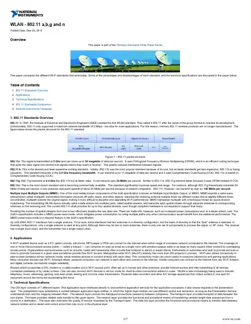
1. 2. 3. 4. 5. WLAN - 802.11 a,b,g and nPublish Date: Dec 03, 2013OverviewThis paper is part of the Wireless Standards White Paper SeriesThis paper compares the different Wi-Fi standards that exist today. Some of the advantages and disadvantages of each standard, and the technical specifications are discussed in the paper below.Table of Contents802.11 Standards OverviewApplicationsTechnical Specifications802.11 Standards ComparisonNational Instruments Hardware1. 802.11 Standards Overview802.11: In 1997, the Institute of Electrical and Electronics Engineers (IEEE) created the first WLAN standard. They called it 802.11 after the name of the group formed to oversee its development.Unfortunately, 802.11 only supported a maximum network bandwidth of 2 Mbps - too slow for most applications. For this reason, ordinary 802.11 wireless products are no longer manufactured. The figure below shows the packet structure for the 802.11 standard.Figure 1 – 802.11 packet structure802.11a : The signal is transmitted at and can move up to of data per second. It uses Orthogonal Frequency-Division Multiplexing (OFDM), which is an efficient coding technique 5 Ghz 54 megabits that splits the radio signal into several sub signals before they reach a receiver. This greatly reduced interference between signals.802.11 b : This is the slowest and least expensive existing standard. Initially, 802.11b was the most popular standard because of its cost, but as faster standards get less expensive, 802.11b is losing popularity. This standard transmits in the It can transmit up to 11 megabits of data per second and it uses Complimentary Code Keying (CCK). 802.11b is based on 2.4 Ghz frequency bandwidth. Complementary Code Keying (CCK).802.11g : 802.11g transmits at like 802.11b but at faster rates. It can transmit upto per second. Similar to 802.11a, 802.11g transmit faster because it uses OFDM instead of CCK.2.4 Ghz 54 Mbits 802.11n : This is the most recent standard and is becoming commercially available. This standard significantly improves speed and range. For instance, although 802.11g theoretically transmits 54Mbits of data per second, it only achieves real-world speeds of about 24 Mbits per second because of network congestion. 802.11n, however, can transmit as high as 140 Mbits per second. Multiple Input Multiple Outputs (MIMO ): One of the most widely known components of the draft specification is known as Multiple Input Multiple Output, or MIMO. MIMO exploits a radio-wave phenomenon called multipath: transmitted information bounces off walls, doors, and other objects, reaching the receiving antenna multiple times via different routes and at slightly different times.Uncontrolled, multipath distorts the original signal, making it more difficult to decipher and degrading Wi-Fi performance. MIMO harnesses multipath with a technique known as space-division multiplexing. The transmitting WLAN device actually splits a data stream into multiple parts, called spatial streams, and transmits each spatial stream through separate antennas to corresponding antennas on the receiving end. The current 802.11n draft provides for up to four spatial streams, even though compliant hardware is not required to support that many.Doubling the number of spatial streams from one to two effectively doubles the raw data rate. There are trade-offs, however, such as increased power consumption and, to a lesser extent, cost. The draft-n specification includes a MIMO power-save mode, which mitigates power consumption by using multiple paths only when communication would benefit from the additional performance. The MIMO power-save mode is a required feature in the draft-n specification.Up until 2004, 802.11 interfaces had a single antenna. To be sure, some interfaces had two antennas in a diversity configuration, but the basis of diversity is that the “best” antenna is selected. In diversity configurations, only a single antenna is used at any point. Although there may be two or more antennas, there is only one set of components to process the signal, or . The receiver RF chain has a single input chain, and the transmitter has a single output chain.2. ApplicationsA Wi-Fi-enabled device such as a PC, game console, cell phone, MP3 player or PDA can connect to the Internet when within range of a wireless network connected to the Internet. The coverage of one or more interconnected access points — called a hotspot — can comprise an area as small as a single room with wireless-opaque walls or as large as many square miles covered by overlapping access points. Organizations and businesses such as airports, hotels and restaurants often provide free hotspots to attract or assist clients. Enthusiasts or authorities who wish to provide services or even to promote business in a given area sometimes provide free Wi-Fi access. Metropolitan-wide Wi-Fi (Muni-Fi) already has more than 300 projects in process. Wi-Fi also allows connectivity in peer-to-peer (wireless ad-hoc network) mode, which enables devices to connect directly with each other. This connectivity mode can prove useful in consumer electronics and gaming applications. Many consumer devices use Wi-Fi. Amongst others, personal computers can network to each other and connect to the Internet, mobile computers can connect to the Internet from any Wi-Fi hotspot,and digital cameras can transfer images wirelessly.Routers which incorporate a DSL-modem or a cable-modem and a Wi-Fi access point, often set up in homes and other premises, provide Internet-access and inter-networking to all devices connected (wirelessly or by cable) to them. One can also connect Wi-Fi devices in ad-hoc mode for client-to-client connections without a router. WLAN is also increasingly being used in Internet telephony, music, streaming, gaming, and even photo viewing and in-home video transmission. Personal video recorders and other A/V storage appliances that collect content in one spot for enjoyment around the home are accelerating this trend.3. Technical SpecificationsThe OSI layer consists of 7 different layers. This application layer interfaces directly to and performs application services for the application processes; it also issues requests to the presentation layer. The presentation layer establishes a context between application layer entities, in which the higher-layer entities can use different syntax and semantics, as long as the Presentation Service understands both and the mapping between them. The session layer controls the dialogues/connections (sessions) between computers. The transport layer provides transport of data between the end clients. This layer provides reliable data transfer to the upper layers. The network layer provides the functional and procedural means of transferring variable length data sequences from asource to a destination. This layer also maintains the quality of service requested by the Transport layer. The data link layer provides the functional and procedural means to transfer data between network entities and to detect and correct errors that may occur in the physical layer.Figure 2 – OSI network modelThe 802.11 standard technologies all support multiple data rates to allow clients to communicate at the best possible speed. Data rate selection is a tradeoff between obtaining the highest possible data rate while trying to minimize the number of communication errors. Whenever there is an error in the data, the systems must spend time to retransmit the data until it is error free. Each 802.11Figure 3 – Range of the different standards802.11a utilizes 300 MHz of bandwidth in the 5 GHz Unlicensed National information Infrastructure (U-NII) band. Though the lower 200 MHz is physically contiguous, the FCC has divided the totalFigure 4 – PPDU frame format Figure 5 – CCK ModulationStart Frame Delimiter. This field is always 1111001110100000 and defines the beginning of a frame.Signal. This field identifies the data rate of the 802.11 frame, with its binary value equal to the data rate divided by 100Kbps. For example, the field contains the value of 00001010 for 1Mbps, 00010100 for 2Mbps, and so on. The PLCP fields, however, are always sent at the lowest rate, which is 1Mbps. This ensures that the receiver is initially uses the correct demodulation mechanism, which changes with different data rates.Service. This field is always set to 00000000, and the 802.11 standard reserves it for future use.Length. This field represents the number of microseconds that it takes to transmit the contents of the PPDU, and the receiver uses this information to determine the end of the frame.Frame Check Sequence. In order to detect possible errors in the Physical Layer header, the standard defines this field for containing 16-bit cyclic redundancy check (CRC) result. The MAC Layer also performs error detection functions on the PPDU contents as well.PSDU. The PSDU, which stands for Physical Layer Service Data Unit, is a fancy name that represents the contents of the PPDU (i.e., the actual 802.11 frame being sent).Figure 6 – Long PLCP PPDU format802.11gThe 802.11g standard includes mandatory and optional components. It uses OFDM, (from 802.11a) and CCK (from 802.11b as the mandatory modulation schemes with 24 Mbps as the maximum mandatory data rate. It also provides for optional higher data rates of 36, 48 and 54 Mbps.The 802.11g standard defines several rate extensions, as part of the specification, to the for the implementation. TheExtended Rate PHY (ERP)PHY Direct Sequence Spread Spectrum (DSSS) PHY ERP–DSSS/CCK ERP–OFDM ERP–PBCC DSSS–OFDM802.11g specification includes four sets of modulation schemes (Mandatory), (Mandatory), (Optional) and (Optional. The initial 802.11PPDUstandard (IEEE Std. 802.11–1999) defines a long preamble PLCP framing and later in standard (IEEE Std. 802.11b, 1999) a short (optional) preamble for the w as defined; however in the PPDU802.1 1g standard the short preamble capability has been defined as mandatory.Figure 7 : ERP-DSSS/CCK PHY Layer PPDU framingAs part of the operational description of the ERP–OFDM modulation scheme, the 802.11g standard specifies that an packet is going to be followed by a period of no transmission with a lengthERPµs.signal extension. The SIFSµs,of 6 This period is called the logic behind this is that in the 802.11a standard the length is defined to be 16 this is to allow for the convolutional decode process toSIFSfinish, as it is described in section 19.3.2.3 of (IEEE Std. 802.11g, 2003). This assumption also applies to the ERP–OFDM in 802.11g; however in the 802.11g standard the length is defined to be 10 presumably to preserve backward compatibility with 802.11b. Nonetheless, in 802.11g, the modulation scheme still requires 16 to ensure the convolutional decoding µs,ERP–OFDMµsµs Duration MAC NAV process to be finished on time. Therefore a signal extension of 6 is included so that the transmitting station can compute the field in the header. This will ensure that the valueERP PHY ERP–DSSS/CCK ERP–OFDMof 802.11b stations is set correctly. The performance study presented in this work is based on the two mandatory specifications, namely the and themodulation scheme.Figure 8 – Short preamble PPDU format for DSSS-OFDMThe figure below shows the modulation schemes for the multiple carriers of 802.11 b, g and a.Figure 9 – Modulation Techniques802.11nThe emerging 802.11n specification differs from its predecessors in that it provides for a variety of optional modes and configurations that dictate different maximum raw data rates. This enables the standard to provide baseline performance parameters for all 802.11n devices, while allowing manufacturers to enhance or tune capabilities to accommodate different applications and price points. With every possible option enabled, 802.11n could offer raw data rates up to 600 Mbps. But WLAN hardware does not need to support every option to be compliant with the standard. In 2006, for example, most draft-n WLAN hardware available is expected to support raw data rates up to 300 Mbps. In comparison, every 802.11b-compliant product must support data rates up to 11 Mbps, and all 802.11a and 802.11g hardware must support data rates up to 54 Mbps.In the 802.11n draft, the first requirement is to support an OFDM implementation that improves upon the one employed in the 802.11a/g standards, using a higher maximum code rate and slightly wider bandwidth. This change improves the highest attainable raw data rate to 65 Mbps from 54 Mbps in the existing standards.Up until 2004, 802.11 interfaces had a single antenna. To be sure, some interfaces had two antennas in a diversity configuration, but the basis of diversity is that the “best” antenna is selected. InRF chaindiversity configurations, only a single antenna is used at any point. Although there may be two or more antennas, there is only one set of components to process the signal, or . The receiver has a single input chain, and the transmitter has a single output chain.The next step beyond diversity is to attach an RF chain to each antenna in the system. This is the basis of Multiple-Input/Multiple-Output (MIMO) operation.* Each RF chain is capable of simultaneous reception or transmission, which can dramatically improve throughput. Furthermore, simultaneous receiver processing has benefits in resolving multipath interference, and may improvespatial streamthe quality of the received signal far beyond simple diversity. Each RF chain and its corresponding antenna are responsible for transmitting a . A single frame can be broken up and multiplexed across multiple spatial streams, which are reassembled at the receiver.PHY LayersIn the 802.11n system, based on the WLAN OFDM system, two new formats are defined for the PLCP (Physical Layer Convergence Protocol): the Mixed Mode and the Green Field. These two formats are called HT (High Throughput) formats. In addition to the HT formats, there is a legacy duplicate format that duplicates the 20 MHz legacy packet in two 20 MHz halves of a 40 MHz channel.So, the 802.11n physical layer operates in one of 3 modes in the time domain: Legacy mode, Mixed Mode and Green Field Mode.In legacy mode and HT mode, transmission is over a 20 MHz channel, and the channel is divided into 64 sub-carriers. Four pilot signals are inserted in sub-carriers -21, -7, 7 and 21. In the legacy mode, signal is transmitted on sub-carriers -26 to -1 and 1 to 26, with 0 being the center (DC) carrier. In the HT modes, signal is transmitted on sub-carriers -28 to -1 and 1 to 28.In the 40 MHz HT transmission, two adjacent 20 MHz channels are used. The channel is divided into 128 sub-carriers. 6 pilot signals are inserted in sub-carriers -53, -25, -11, 11, 25, 53. Signal is transmitted on sub-carriers -58 to -2 and 2 to 58.In the case of the legacy duplicate mode over 40 MHz, the same data are transmitted over two adjacent 20 MHz channels. In this case the 40 MHz channel is divided into 128 sub-carriers and the data are transmitted on carriers -58 to -6 and 6 to 58.Legacy Mode: In the legacy mode, frames are transmitted in the legacy 802.11a/g OFDM format.Mixed Mode: In the Mixed Mode, packets are transmitted with a preamble compatible with the legacy 802.11a/g. The legacy Short Training Sequence, the legacy Long Training sequence, and the legacy signal description are transmitted so they can be decoded by legacy 802.11a/g devices. The rest of the packet has a new MIMO training sequence format. Figure 2 shows the Mixed Mode format. Click the various parts of the figure for more details on each field.Green Field Mode: In the Green Field mode, high throughput packets are transmitted without a legacy-compatible part. Figure 3 shows the Green Field format. Click the various parts of the figure for more details on each field.Figure 10 – PHY LayersLegacy Short Training Field (L-STF) The legacy short training OFDM symbol is identical to the 802.11a short training OFDM symbol. The L-STF is BPSK modulated at 6 Mbps. It contains no channel coding, and is not scrambled. The L-STF has a period of 0.8 µs. The entire short training field includes ten such periods, with a total duration of 8 µs.Legacy Long Training Field (L-LTF) The legacy long training OFDM symbol is identical to the 802.11a long training OFDM symbol. The L-LTF is BPSK modulated at 6 Mbps. It contains no channel coding, and is not scrambled.Legacy Signal Field (L-SIG) The signal field is used to transfer rate and length information. The L-SIG consists of one OFDM symbol assigned to all 52 subcarriers. This symbol is BPSK modulated at 6 Mbps and is encoded at a ½ rate. L-SIG is interleaved and mapped, and has pilots inserted in subcarriers –21, –7, 7 and 21. The L-SIG is not scrambled.High Throughput Signal Field (HT-SIG) The high throughput signal field is used to carry information required to interpret the HT packet formats. The HT-SIG is composed of two parts HTSIG1 and HTSIG2, each containing 24 bits. All the fields in the HT-SIG are transmitted LSB first.High Throughput Short Training Field (HT-STF) The purpose of the High Throughput Short Training Field is to improve AGC (Automatic Gain Control) training in a multi-transmit and multi-receive system. The duration of the HT-STF is 4μsec.High Throughput Long Training Field (HT-LTF) The High Throughput Long Training field provides means for the receiver to estimate the channel between each spatial mapping input (or spatialHigh Throughput Long Training Field (HT-LTF) The High Throughput Long Training field provides means for the receiver to estimate the channel between each spatial mapping input (or spatial stream transmitter if no STBC is applied) and receive chain; the number of training symbols is equal or greater than the number of space-time streams (with an exception in the case of 3 space-time streams).The HT-LTF portion has one or two parts. The first part consists of from one to four HT long training fields (HT-LTFs) that are necessary for demodulation of the HT-Data portion of the PPDU. These HT-LTFs are referred to as Data HT-LTFs. The optional second part consists of from zero to four HT-LTFs that may be used to probe extra spatial dimensions of the MIMO channel that are not utilized by the HT-Data portion of the PPDU. These HT-LTFs are referred to as Extension HT-LTFs. If a receiver has not advertised its ability to receive Extension HT-LTFs, it may discard a frame including Extension HT-LTFs as an unknown frame type.Both the WWiSE and TGnSync proposals employ MIMO technology to boost the data rate, though their applications differ. MIMO antenna configurations are often described with the shorthand “YxZ,” where Y and Z are integers, used to refer to the number of transmitter antennas and the number of receiver antennas. For example, both WWiSE and TGnSync require 2x2 operations, which has two transmit chains, two receive chains, and two spatial streams multiplexed across the radio link. Both proposals also have additional required and optional modes. I expect that the common hardware configurations will have two RF chains on the client side to save cost and battery power, while at least three RF chains will be used on most access points. This configuration would use 2x3 MIMO for its uplink and 3x2 MIMO on the downlink.Figure 11- Aggregation in WWiSEFigure 12- Bursting in WWiSEWWiSE PLCPThe PLCP must operate in two modes. In Greenfield mode, it operates without using backwards-compatible physical headers. Greenfield access is simpler: it can operate without backwards compatibility. The figure below shows PLCP encapsulation.Figure 13 – WwiSE PLCPThe SIGNAL-N fieldThe SIGNAL-N field is used in all transmission modes. It has information to recover the bit stream from the data symbols. The SIGNAL-N field is shown below.Figure 14 – The Signal – N FieldThe Figure below shows the basic format of a single physical-layer frame containing several MAC layer frames.Figure 15 - TGnSyncFrame Aggregation4. 802.11 Standards Comparison802.11a802.11a operates at the fastest speed and supports more simultaneous users. The operating frequencies of 802.11 a are regulated and this prevents interference from other devices.OFDM has fundamental propagation advantages when in a high multipath environment, such as an indoor office, and the higher frequencies enable the building of smaller antennas with higher RF system gain which counteract the disadvantage of a higher band of operation. The increased number of usable channels (4 to 8 times as many in FCC countries) and the near absence of other interfering systems, (microwave ovens, cordless phones, baby monitors) give 802.11a significant aggregate bandwidth and reliability advantages over 802.11b/g.Since the 2.4 GHz band is heavily used to the point of being crowded, using the 5 GHz band gives 802.11a a significant advantage. However, this high carrier frequency also brings a slight disadvantage: The effective overall range of 802.11a is slightly less than that of 802.11b/g; 802.11a signals cannot penetrate as far as those for 802.11b because they are absorbed more readily by walls and other solid objects in their path.802.11b802.11b is the lowest cost amongst the standards and the signal range is the best. The signal is not easily obstructed either.Some of the disadvantages are that is has the slowest maximum speed and supports fewer simultaneous users. The appliances may also interfere on the unregulated frequency band.Since the selection of the 802.11g draft standard technology, some observers have questioned the merits of continuing development activity in the 2.4 GHz band. The reasoning has predominantly cited the increased crowding of this spectrum, versus that of the relatively clearer 5.2 GHz spectrum utilized by802.11a. Certainly the past performance of already-installed 802.11b networks provides evidence that the 2.4 GHz band is well suited to wireless networking and the 802.11b devices have continued to provide excellent performance in the presence of increasing interference. In addition, the 2.4 GHz ISM band is available throughout the world with relatively few, if any, regulatory restrictions. In contrast, the 5.2 GHz band is used by military applications such as high-energy radar and, as a result, several major global markets, including Western Europe and Japan, have to date placed regulatory restrictions on the commercial use of this band. Even in the United States there are questions concerning security risks for military operations with 802.11aoperating in the 5.2 GHz band. Utilizing the 2.4 GHz band ensures that 802.11gWLANs will avoid the regulatory restrictions that are likely to been countered, while offering backwards compatibility with 802.11b systems.802.11g802.11g has a fast maximum speed and support simultaneous users. The signal range is the best and is not easily obstructed either.Some of the disadvantages are that it costs more than 802.11b and some of the appliances may also interfere with the unregulated signal frequency.802.11nOne of the most widely known components of the draft specification is known as Multiple Input Multiple Output, or MIMO. MIMO exploits a radio-wave phenomenon called multipath: transmitted information bounces off walls, doors, and other objects, reaching the receiving antenna multiple times via different routes and at slightly different times. Uncontrolled, multipath distorts the original signal, making it more difficult to decipher and degrading Wi-Fi performance. MIMO harnesses multipath with a technique known as space-division multiplexing. The transmitting WLAN device actually splits a data stream into multiple parts, called spatial streams, and transmits each spatial stream through separate antennas to corresponding antennas on the receiving end. The current 802.11n draft provides for up to four spatial streams, even though compliant hardware is not required to support that many. Doubling the number of spatial streams from one to two effectively doubles the raw data rate. There are trade-offs, however, such as increased power consumption and, to a lesser extent, cost. The draft-n specification includes a MIMO power-save mode, which mitigates power consumption by using multiple paths only when communication would benefit from the additional performance. The MIMO powersave mode is a required feature in the draft-n specification.Another optional mode in the 802.11n draft effectively doubles data rates by doubling the width of a WLAN communications channel from 20 MHz to 40 MHz. The primary trade-off here is fewer channels available for other devices. In the case of the 2.4-GHz band, there is enough room for three non-overlapping 20-MHz channels. Needless to say, a 40-MHz channel does not leave much room for other devices to join the network or transmit in the same airspace. This means intelligent, dynamic management is critical to ensuring that the 40-MHz channel option improves overall WLAN performance by balancing the high-bandwidth demands of some clients with the needs of other clients to remain connected to the network.5. National Instruments HardwareNational Instruments provides products for both Vector Signal Analysis and Vector Signal Generation. Using the Modulation toolkit different modulation techniques can be used to test and implement the various standards.PXIe-5672 PXI-5661。