宝马5系E60手册技术资料:mfp-brk-e60-rohhk-basic-update_en
- 格式:pdf
- 大小:4.32 MB
- 文档页数:51
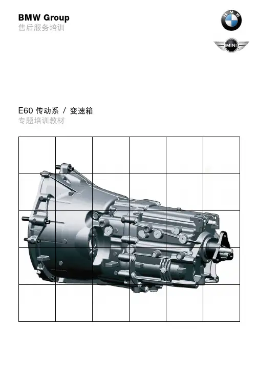
BMW Group售后服务培训E60传动系/变速箱专题培训教材提示本培训手册中包含的信息仅用于接受售后服务培训的人员。
技术数据的更改 / 补充摘自“BMW 售后服务”的有关信息。
© 2003 BMW AG慕尼黑,德国。
没有宝马汽车公司的书面授权,任何人不得再版、复制及摘录VS-12/Vs-42 MFP-HGK-BRK-0300_update目录页码第一章引言1 - 手动变速箱3-自动换档控制的手动变速箱(SMG)3- 自动变速箱3- 传动轴,后桥差速器,输出轴3手动变速箱4- 技术数据5- H 变速箱的特点5- H 变速箱发动机侧的特点10-维修说明12自动换档控制的手动变速箱(SMG)13- 系统一览14- 部件22- 系统功能25- 国家规格27-维修说明28自动变速箱30- 系统一览32- 部件38- 系统功能43- 维修说明46传动轴,后桥差速器,输出轴50- 系统一览50- 部件51-维修说明60引言在 E60 中可分别使用 2 种手动变速箱、自动换档控制的手动变速箱(SMG )和自动变速箱系列以及 2 种后桥差速器(取决于发动机 - 变速箱组合)系列。
组合系列和选择装备(SA )变速箱名称手动变速箱、自动换档控制的手动变速箱(SMG )和自动变速箱按照 BMW 集团标准(GS )90007 进行命名。
后桥差速器例外。
它命名为 188K 或者 215K 。
发动机系列自动变速箱选择装备自动换档控制的手动变速箱(SMG )选择装备后桥差速器M54B22GS6-37BZ GA6HP19Z H-SMG 188K M54B30GS6-37BZ GA6HP19Z H-SMG 188K N62B44GS6-53BZ GA6HP26Z G-SMG 215K M57D30TUGS6-53DZGA6HP26Z---215K动态行驶控制(FDC)动态行驶控制(FDC)的功能与自动换档控制的手动变速箱一起批量生产安装。
BMW Group售后服务培训E60高级安全电子设备专题培训教材提示本培训手册中包含的信息仅用于接受 BMW 售后服务培训课程的人员。
技术数据的更改/补充摘自“技术售后服务”的有关信息。
© 2003 BMW AG慕尼黑,德国。
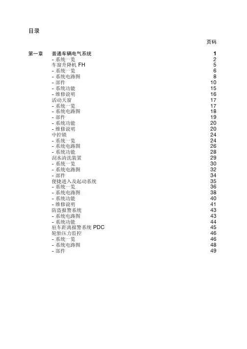
没有宝马汽车公司的书面授权,任何人不得再版、复制及摘录VS-12/Vs-42 MFP-HGK-BRK-1000_update目录页码第一章高级安全电子设备 ASE1引言1- 高级安全电子设备中的新技术2- 系统优点3系统一览4- 总线一览4- 系统一览欧规车6- 系统电路图(欧规车)8部件(欧规车)10- byteflight12- 安全和网关模块 SGM13- 左侧 / 右侧 B 柱卫星式控制单元 SBSL/SBSR18- 驾驶员侧 / 前乘客侧车门模块 TMFA/TMBF20- 车辆中央卫星式控制单元 SFZ24- 转向柱开关中心 SZL25- 安全带锁扣开关28- 座位占用识别装置29- 蓄电池导线诊断30- 驾驶员前部安全气囊34- 前乘客前部安全气囊35- 高级 ITS(头部安全气囊)36- 侧面安全气囊38- 安全带拉紧装置39- 主动式头枕41- 安全蓄电池接线柱 SBK43系统功能44- 触发规则44- 欧规车紧急呼叫50美规车52- 引言52美规车系统一览53部件57维护说明65高级安全电子设备 ASE引言高级安全电子设备 ASE 作为一种新型被动安全系统,用于 E60 及该系列的其他车型。
ASE 取代了迄今使用的 MRS 系统(多重乘员保护系统)。
该系统与 E65/E66 车型中的智能型全面安全系统 ISIS 采用了相同的技术。
ASE 是为满足 E60 车型的要求而专门设计的。
- 高级安全电子设备中的新技术与 E65/66 车型相同,在 E60 车型中使用了新的光缆技术byteflight(BMW 安全总线系统)。
ASE 系统由一个主控制单元、安全和网关模块 SGM 和多个卫星式控制单元组成。
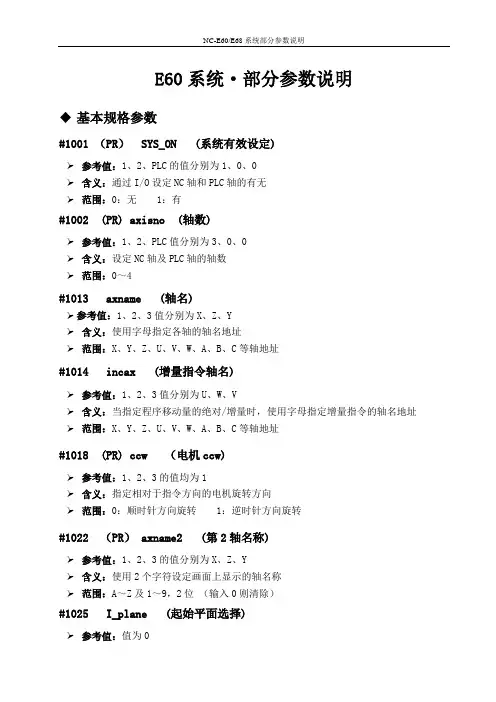
E60系统·部分参数说明◆基本规格参数#1001 (PR) SYS_ON (系统有效设定)➢参考值:1、2、PLC的值分别为1、0、0➢含义:通过I/O设定NC轴和PLC轴的有无➢范围:0:无 1:有#1002 (PR) axisno (轴数)➢参考值:1、2、PLC值分别为3、0、0➢含义:设定NC轴及PLC轴的轴数➢范围:0~4#1013 axname (轴名)➢参考值:1、2、3值分别为X、Z、Y➢含义:使用字母指定各轴的轴名地址➢范围:X、Y、Z、U、V、W、A、B、C等轴地址#1014 incax (增量指令轴名)➢参考值:1、2、3值分别为U、W、V➢含义:当指定程序移动量的绝对/增量时,使用字母指定增量指令的轴名地址➢范围:X、Y、Z、U、V、W、A、B、C等轴地址#1018 (PR) ccw (电机ccw)➢参考值:1、2、3的值均为1➢含义:指定相对于指令方向的电机旋转方向➢范围:0:顺时针方向旋转 1:逆时针方向旋转#1022 (PR) axname2 (第2轴名称)➢参考值:1、2、3的值分别为X、Z、Y➢含义:使用2个字符设定画面上显示的轴名称➢范围:A~Z及1~9,2位(输入0则清除)#1025 I_plane (起始平面选择)➢参考值:值为0➢含义:指定将接通电源时及复位时的平面选择设定为哪个平面➢范围:0、1:X-Y平面 2:Z-X平面 3:Y-Z平面#1026 base_I (基本轴I)#1027 base_J (基本轴J)#1028 base_K (基本轴K)➢参考值:base_I、_J、_K依次指定为X、Y、Z➢含义:指定构成平面的基本轴的地址➢范围:X、Y、Z等控制轴地址#1037 cmdtyp (指令类型)➢参考值:3➢含义:指定程序的G代码体系与补偿类型;cmdtyp G代码体系补偿类型3 系列2(L用)类型C(对于一个补偿编号,设置形状、磨损两种补偿量)➢范围:1~8#1043 lang (显示语言选择)➢参考值:22➢含义:指定显示语言 22:汉语(简体字)➢范围:0~3、11~22#1073 I_Absm (起始绝对值)➢参考值:1➢含义:指定接通电源时及复位时的绝对值/增量值模式➢范围:0:增量值指令模式 1:绝对值指令模式#1076 AbsInc (ABS/INC 地址)➢参考值:1➢含义:对于同一轴,可通过分别使用绝对值用/增量值用的两个地址,进行绝对值/ 增量值的指令➢范围:0:绝对/增量根据G指令决定 1:绝对/增量根据地址代码决定#1084 RadErr (圆弧误差)➢参考值:0.1➢含义:在圆弧指令中,指定终点与中心坐标存在偏差时允许误差范围➢范围:0~1,000(mm)#1155 DOOR_m (系统共用门互锁Ⅱ用信号输入设备1)➢参考值:100➢含义:当不使用门互锁Ⅱ的固定设备编号时,设定为“100”➢范围:000~100(16进制)#1156 DOOR_s (系统共用门互锁Ⅱ用信号输入设备2)➢参考值:100➢含义:当不使用门互锁Ⅱ的固定设备编号时,设定为“100”➢范围:000~100(16进制)#1174 skip_F (G31跳跃速度)➢参考值:100➢含义:指定G31(跳跃)指令时,程序中没有F指令时的进给速度➢范围:0~999999(mm/min)#1185 spd_F1 (F1 数位进给速度)#1186 F2 (F2 数位进给速度)#1187 F3 (F3 数位进给速度)#1188 F4 (F4数位进给速度)#1189 F5 (F5 数位进给速度)➢参考值:spd_F1、F2、F3、F4、F5依次指定为100、200、300、400、500 ➢含义:指定F n时的速度(mm/min)➢范围:1~60000(mm/min)#1240 (PR) set12 (bit0) (手轮输入脉冲切换)➢参考值:0➢含义:选择手轮的输入脉冲0:手轮支持100脉冲(+12V电源)1:手轮支持400脉冲(+5V电源)➢范围:0/1#1534 SnG44.1 (G44.1指令时的主轴编号)➢参考值:1➢含义:设定G44.1指令时的选择主轴编号➢范围:0:第2主轴 1:第1主轴 2:第2主轴◆轴规格参数#2001 rapid (快速进给速度)➢参考值:X、Z、Y的值均为10000➢含义:设定各轴的快速进给速度,其最大值取决于机械系统➢范围:1~999999(mm/min)#2002 clamp (切削进给负载速度)➢参考值:X、Z、Y的值均为4000➢含义:定义各轴的切削进给最高速度➢范围:1~999999(mm/min)#2003 (PR) smgst (加减速模式)➢参考值:X、Z、Y的值均为0021➢含义:指定加减速控制模式 2:bit7~4,0010,类型:一次延迟(切削进给)1:bit3~0,0001,类型:直线加、减速(快速进给)➢范围:以HEX设定#2004 G0tL (G0时间常数(线性))➢参考值:X、Z、Y的值均为100➢含义:设定快速进给加减速中,直线控制的加减速时间常数➢范围:1~4000(ms)#2005 G0t1 (G0时间常数(1次延迟))➢参考值:X、Z、Y的值均为100➢含义:设定快速进给加减速中1次延迟时间常数➢范围:1~5000(ms)#2007 G1tL (G1时间常数(线性))➢参考值:X、Z、Y的值均为30➢含义:设定切削进给加减速中的直线控制时间常数➢范围:1~4000(ms)#2008 G1t1 (G1时间常数(1次延迟))➢参考值:X、Z、Y的值均为30➢含义:设定切削进给加减速中的1次延迟时间常数➢范围:1~5000(ms)#2011 G0back (G0齿隙)➢参考值:X、Z、Y的值分别为0、120、0➢含义:设定快速进给模式下的移动指令或手动模式中,当方向翻转时进行补偿的齿隙量➢范围:-32768~32767#2012 G1back (G1齿隙)➢参考值:X、Z、Y的值分别为0、120、0➢含义:设定切削进给模式中执行了移动指令时,对方向翻转进行补偿的齿隙量➢范围:-32768~32767#2013 OT- (软件限制I-)#2014 OT+ (软件限制I+)➢参考值:X、Z、Y的设定值以实际值为准➢备注:当回零点完成以后,该设定值都要重新输入➢含义:设定以基本机械坐标的零点为基点的软件限位区域。
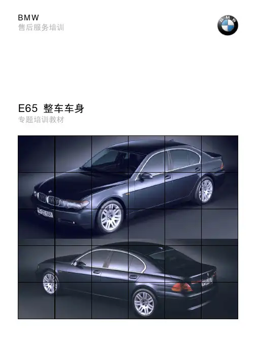
BMW Group售后服务培训E60整车车身专题培训教材For Evaluation Only.Copyright (c) by Foxit Software Company, 2004Edited by Foxit PDF Editor提示本培训手册中包含的信息仅用于接受 BMW 售后服务培训课程的人员。
技术数据的更改/补充请查阅“技术售后服务”中的相应信息。
© 2002 BMW AG慕尼黑,德国。
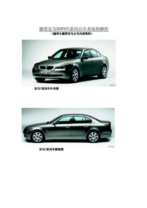
没有宝马汽车公司的书面授权,任何人不得再版、复制及摘录VS-42 MFP-HGK-BRK-E60_0220目录页码第一章E60 整车车身1引言1前部车身部件5- 车前盖5- 前部侧围5- 发动机室6- 大灯7- 前雾灯8- 前保险杠9- 前围总成10- 挡风玻璃11- 玻璃清洗装置12- 外后视镜13- 嵌条、车门槛盖板14- 前车门15- 车内控制单元的安装位置17- 仪表板22- 中央控制台24- 前座椅26- 后座椅30- 安全气囊32尾部车身部件32- 后侧围32- 后行李箱盖32- 后窗玻璃34- 行李箱35- 行李箱内控制单元的安装位置36- 尾灯39- 后保险杠41活动天窗42车辆底部44E60 整车车身引言2003 年上半年 E60 接替了 E39 开始在 Dingolfing 的工厂投产。
E60 是传统 5 系轿车的进一步发展。
(E12 - E28 - E34 - E39 - E60)图 1: E60 前视图车型 E60从 2003 年 9 月起 525i 和 545i 将投放市场。
520i530i530dKT-11012图 2: E60 侧面尺寸图 3: 高度/宽度尺寸图mm E60E39差值长度48414775+ 66宽度18461800+ 46高度14691435+ 34KT-11013KT -11142图 4: 长度尺寸图重量虽然 E60 比 E39 更长、更宽且更高,但是其全装备重量却降低了约 36kg 。
BMW Group 售后服务培训E60燃油系统专题培训教材提示本培训手册中包含的信息仅用于接受 BMW 售后服务培训课程的人员。
技术数据的更改/补充摘自“BMW 售后服务”的有关信息。
© 2003 BMW AG慕尼黑,德国。
没有宝马汽车公司的书面授权,任何人不得再版、复制及摘录VS-12/Vs-42 MFP-HGK-BRK-0330_update目录页码第一章燃油系统1引言1系统一览2- 燃油系统,欧规2- 燃油系统,柴油规格4- 燃油系统,美规6部件8- 燃油箱8- 燃油输送单元12- 缓冲装置13- 燃油输送14- 燃油油位传感器16- 活性碳过滤器(AKF)16系统功能17- 运行排气17- 加注管排气19系列20燃油系统引言为了适应排放法规越来越严格的要求,燃油系统尽量减少开口和接头的数量。
例如:汽油发动机中的燃油滤清器和压力调节器都安装在油箱内。
系统一览- 燃油系统,欧规KT-12000图 1: 燃油系统(欧规)序号说明序号说明1燃油加注管接头13维护开口,右侧2安全阀14加注管排气接头3电动燃油泵(EKP)15运行排气阀(翻车保护阀)4燃油滤清器16运行排气阀(翻车保护阀)5进油管路17活性碳过滤器(AKF)6喷油轨/喷油阀18燃油箱排气阀(TEV)7燃油压力调节器19从 AKF 至进气系统的吹洗空气8引流泵,左侧20空气滤清器(滤网)9引流泵,右侧21数字式发动机电子伺控系统(DME)10燃油油位传感器,右侧22氧传感器11燃油油位传感器,左侧23排气歧管12维护开口,左侧- 燃油系统,柴油规格KT-12006图 2: 燃油系统(柴油发动机)序号说明序号说明1燃油加注管接头11燃油油位传感器,右侧2安全阀12燃油油位传感器,左侧3电动燃油泵(EKP)13维护开口,左侧4燃油滤清器14加注管排气接头5进油管路15维护开口,右侧6高压泵16运行排气阀(翻车保护阀)7共轨 / 喷油阀17空气滤清器(滤网)8回流管路18空气滤清器9引流泵,左侧19排气歧管10引流泵,右侧- 燃油系统,美规KT-12005图 3: 燃油系统(美规,汽油发动机)序号说明序号说明1燃油加注管接头13维护开口,右侧2安全阀14加注排气阀3电动燃油泵(EKP)15运行排气阀(翻车保护阀)4燃油滤清器16运行排气阀(翻车保护阀)5进油管路17用于油箱泄漏(DMTL)以及活性碳过滤器(AKF)的诊断模块6喷油轨 / 喷油阀18燃油箱排气阀(TEV)7燃油压力调节器19从 AKF 至进气系统的吹洗空气8引流泵,左侧20空气滤清器(滤网)9引流泵,右侧21数字式发动机电子伺控系统(DME)10燃油油位传感器,右侧22氧传感器11燃油油位传感器,左侧23排气歧管12维护开口,左侧部件- 燃油箱图 4: E60,仰视图序号说明1燃油箱KT-11185燃油箱的容量为 70升。
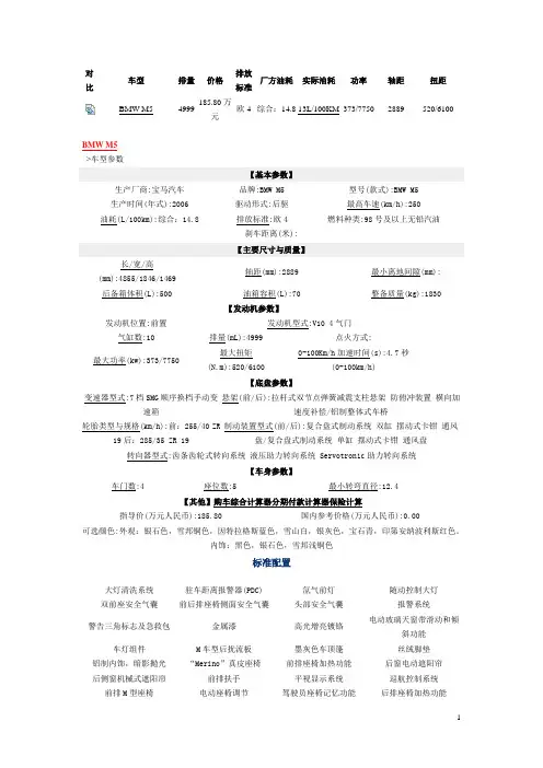
对比车型 排量 价格 排放标准 厂方油耗 实际油耗 功率 轴距 扭距BMW M5 4999 185.80万元 欧4 综合:14.8 13L/100KM 373/7750 2889 520/6100BMW M5>车型参数 【基本参数】生产厂商:宝马汽车品牌:BMW M5 型号(款式):BMW M5 生产时间(年式):2006驱动形式:后驱 最高车速(km/h):250 油耗(L/100km):综合:14.8 排放标准:欧4 燃料种类:98号及以上无铅汽油刹车距离(米):【主要尺寸与质量】长/宽/高(mm):4855/1846/1469 轴距(mm):2889 最小离地间隙(mm): 后备箱体积(L):500 油箱容积(L):70整备质量(kg):1830 【发动机参数】发动机位置:前置发动机型式:V10 4气门 气缸数:10排量(mL):4999 点火方式: 最大功率(kw):373/7750 最大扭矩(N.m):520/61000-100Km/h 加速时间(s):4.7秒(0-100km/h) 【底盘参数】变速器型式:7档SMG 顺序换档手动变速箱 悬架(前/后):拉杆式双节点弹簧减震支柱悬架 防俯冲装置 横向加速度补偿/铝制整体式车桥 轮胎类型与规格(km/h):前:255/40 ZR 19后:285/35 ZR 19 制动装置型式(前/后):复合盘式制动系统 双缸 摆动式卡钳 通风盘/复合盘式制动系统 单缸 摆动式卡钳 通风盘转向器型式:齿条齿轮式转向系统 液压助力转向系统 Servotronic 助力转向系统【车身参数】车门数:4 座位数:5 最小转弯直径:12.4【其他】购车综合计算器分期付款计算器保险计算指导价(万元人民币):185.80 国内参考价格(万元人民币):0.00可选颜色:外观:银石色,雪邦铜色,因特拉格斯蓝色,雪山白,银灰色,宝石青,印第安纳波利斯红色。
内饰:黑色,银石色,雪邦浅铜色标准配置大灯清洗系统驻车距离报警器(PDC) 氙气前灯 随动控制大灯 双前座安全气囊前后排座椅侧面安全气囊 头部安全气囊 报警系统 警告三角标志及急救包金属漆 高光增亮镀铬 电动玻璃天窗带滑动和倾斜功能 车灯组件M 车型后扰流板 墨灰色车顶篷 丝绒脚垫 铝制内饰,暗影抛光“Merino”真皮座椅 前排座椅加热功能 后窗电动遮阳帘 后侧窗机械式遮阳帘前排扶手 平视显示系统 巡航控制系统 前排M 型座椅电动座椅调节 驾驶员座椅记忆功能 后排座椅加热功能扩展型自动空调吸烟配套前排腰部支撑BMW专业导航系统电视接收功能BMW专业级收音机高保真专业级音响系统LOGIC7车载蓝牙系统CD换碟机【选装配置】【本车配置】宝马M5 VS. 奔驰E55AMG 2002年06月17日16:36 汽车族这两种车经过多次的对比测试,而且每次似乎都是势均力敌。

SheerDriving PleasureLINK:CONTENT & A-Z欢迎驾乘 BMW。
用户手册。
恭喜您选择了BMW。
您对您的汽车越熟悉,您就会发现驾驶它越轻松自如。
因此我们请您:在启动您的BMW新车之前,请仔细阅读本用户手册。
请您也使用车内集成式用户手册。
您将得到车辆操作的重要提示,有助于您充分利用BMW的技术优势。
此外,您还会得到对本车运行安全性和交通安全性以及BMW汽车最佳保值非常有用的信息。
在工厂生产车辆时,印刷版用户手册即为最新版媒体。
车辆软件升级后,例如远程软件升级,车辆的集成式用户手册收到最新信息。
有关的补充信息请见车载资料的其他手册。
衷心祝愿您旅程安全愉快!3目录车辆软件升级后,例如远程软件升级,车辆的集成式用户手册收到最新信息。
提示提示 (6)用户手册的媒体 (17)简要说明登车 (20)调整和操作 (24)在路上 (28)操作驾驶室 (34)车辆的运行状态 (39)iDrive (42)BMW远程软件升级 (57)一般设置 (60)个人设置 (64)连接 (69)打开和关闭 (76)座椅、后视镜和方向盘 (103)儿童安全乘车 (117)驾驶 (124)显示 (139)车灯 (157)安全 (164)行驶稳定控制系统 (200)驾驶员辅助系统 (204)行驶舒适性 (249)空调 (251)内部装备 (265)存物架 (271)行李厢 (275)4驾驶提示驾驶时应注意的事项 (280)节省燃油 (285)顺利驾驶加油 (290)车轮和轮胎 (292)发动机室 (312)工作液 (315)保养 (321)零部件的更换 (323)故障救援 (327)养护 (334)便捷查阅技术参数 (338)附录 (339)从 A 至 Z (340)© 2020 Bayerische Motoren WerkeAktiengesellschaft德国, 慕尼黑未经慕尼黑 BMW AG 的书面许可不得再版或摘录。
%0: *URXS $IWHUVDOHV7UDLQLQJ( 'LVSOD\V DQG &RQWUROV 3DUWLFLSDQW 0DQXDONOTEThe information contained in this participant's manual is intended for participants of the Aftersales Training.Refer to the relevant "BMW Service" information for any changes/ supplements to the Technical Data.© 2003 BMW AGMünchen, Germany. Reprints of this manual or its partsrequire the written approval of BMW AG, MünchenVS-12/VS-42 MFP-HGK-BRK-E63_1100ContentsPage CHAP 1Displays and Controls1 Condition Based Service (CBS)8- Block diagram8US instrument cluster9Central Information Display (CID)10Components11Head-up display32System overview33- Input/Output35- System circuit diagram37Components39- Head-up display42- Display area of head-up display50- Control elements52- Adjusting HUD brightness53Service information54ConnectedService58Condition Based Service (CBS)59TeleService167Displays and ControlsThis participant's manual describes the display and control design for the new BMW 6 Series. It is divided into the following sections:-Instrument cluster (changes compared to E60)-Central Information Display (changes compared to E60)-Head-up display-ConnectedService (changes compared to E60).Instrument clusterAll driving-related displays in the instrument cluster have been further optimized.In the E63, the road speed is now displayed in the form of a detailed scale.Furthermore, the economy control is replaced by the oil temperature gauge.Central Information DisplayThe Central Information Display is the graphic display unit for the user interface of all convenience functions and some vehicle functions.By contrast with the E65,the CID in the E63has just four menu items in the global main menu, namely Communication, Navigation, Enter-tainment and Climate.There are two versions of the controller for the E63,a basic variant and a High variant.The basic variant is only installed in conjunction with the mid-size 6.5" colour display.Head-up displayFor the first time at BMW, a head-up display is used in the E60/E63.This display shows important information in the driver's direct field of vision. A projection unit integrated in the instrument cluster generates the virtual image and projects it onto the windscreen.Corresponding to the vehicle equipment configuration, information on the navigation system, cruise control, active cruise control, the current road speed as well as check control warning messages is displayed. ConnectedServiceConnectedService is made up of several modules; some of these are already in use while others have been further developed or introduced for the first time with the launch of the E60 and E63.For instance,ease of servicing has been improved thanks to expanded or modified service options in the Condition Based Service (CBS) system.The logical continuation of the innovative service concept is demon-strated by the new display functions, the service reception module, SAM 2, and the introduction of T eleService 1.A detailed description of all T eleService functions and associated appli-cation examples can be found in a training and information program (SIP).Instrument clusterOn the E63, the road speed is now displayed in the form of a detailed scale and the economy control is replaced by the oil temperaturegauge.The scales on the instrument cluster are specific to each country,vehicle and engine.KT-12082Fig. 1:E60 and E63 Instrument clusterDisplay areasThe instrument cluster is divided into the following display areas: -Instrument dials-Indicator and warning lamps-LC display-Program and gear displays for automatic gearbox and SMG Sequential Manual GearboxKT-12082Fig. 2:Display areas in the instrument cluster E60 and E63Instrument dialsThe instrument cluster includes the following dials:-Speedometer-Rev counter-Fuel gauge-Fuel consumption (economy) indicator-Oil temperature gauge (E63 only)KT-10883Fig. 3:Instrument dials E60Index Explanation1Set speed for cruise control system2Speedometer E603Rev counter4Rev counter speed warning zone5Economy control (oil temperature gauge on E63)6Fuel gaugeEngine speed warning zoneThe maximum engine speed warning display is indicated by the rev counter as a function of engine temperature.The following table lists the main engine speed warning zones:Engine variant Petrol engine Diesel engineStart of variable warning zone4200 rpm3500 rpmEnd of variable warning zone6300 rpm4800 rpmStart of fixed warning zone6500 rpm5000 rpmEnd of fixed warning zone7000 rpm5500 rpmKT-11231Fig. 4:Rev counter warning zones for petrol engines E63Index Explanation1Start of variable warning zone2End of variable warning zone3Start of fixed warning zone4End of fixed warning zoneOil temperature gaugeOn the E63, the economy control is replaced by the oil temperaturegauge.The DME control unit makes available the value indicated in the instrument cluster via the PT-CAN and K-CAN.KT-12048Fig. 5:Oil temperature gauge E63Condition Based Service (CBS)- Block diagramAll information that the CBS system requires is sent on the K-CAN bus.The instrument cluster is a subscriber on the K-CAN and acts as theCBS master control unit.The CBS requests from all the control units are therefore sent via theK-CAN to the instrument cluster and to the Central Information Display.KT-11135Fig. 6:Block diagram of the Condition Based Service (CBS)US instrument clusterThe main difference between the US version and the one for EU LHD vehicles is the speed scale, which on the US version is shown in both mph (miles per hour) and in km/h (kilometres per hour).There are also differences in the program and gear display in theinstrument cluster, depending on which transmission is installed.The program and gear display is only used on vehicles with automatic gearboxes or SMG sequential manual gearboxes.KT-11197Fig. 7:Instrument cluster E63, USA versionThere are also differences in the indicator and warning lamps:-The general brake warning light symbol is replaced by the word BRAKE-The indicator lamp for the rear fog lights is not activated-The check engine symbol is replaced by SERVICE ENGINE SOONCentral Information Display (CID)The CID is the graphic display unit for the user interface of the navigation, audio, climate control and communications systems. Unlike the E65, the CID has just four items in the main menu. It has therefore been adapted to the level of optional equipment for the E60 and E63.As on the E65, it is operated from the central control element, the controller.ComponentsThe Central Information Display (CID) comprises the following compo-nents:-LC display-Controller-Displays in the CIDLC displayIn order to cope with the various equipment specifications, the following variants are used for the E60/E63:-CID Mid with 6.5" colour LCD (400 x 240 pixels)-CID High with 8.8" colour LCD (640 x 240 pixels)The LCD also features a help windowThe casing is designed to be able to accommodate all screen variants offered.The entire Central Information Display assembly is fixed to the dashboard by two screws.KT-12191Fig. 8:Central Information Display E60 and E63Index Explanation1 6.5" Mid colour LCD CID28.8" High colour LCD CIDDisplays in the Central Information DisplayThe 6.5" colour LC display, with a resolution of 400 x 240 pixels (width x height), is divided into a display zone and a status bar.The main menu display comprises the following four menu items:-Communication-Navigation-Entertainment-ClimateThe four menu items are displayed in a cross pattern on the Central Information Display corresponding to the four main directions in which the controller can be moved.In addition to these four main menu items, there is a fifth menu item used exclusively for individual user settings. The screen can also be switched on and off from this menu.The menu can be called up by pressing the controller.The following diagram is a schematic representation showing how the controller and the display of the individual menus on the Central Infor-mation Display interact.All screen shots shown are derived from a simulation of a version with featuring a 6.5" Mid colour LC display and correspond to the status at the time of going to press.Further changes are possible to the contents and the layout.KT-11531Fig. 9:User interface of the Central Information Display for the E60 and E63Status barThe status bar displays the main information on the various functions, such as the telephone signal strength or the time; this information is permanently displayed after Ignition ON.KT-11511Fig. 10:CID status barIndex Explanation1Automatic air conditioning system activated2Audio source activated3TMC (T raffic Message Channel) activated4Unread text message (SMS)5T elephone signal strength6TimeCOMMUNICATION menuIn this menu, entries in the telephone directory can be displayed and sorted according to various criteria. Here too, the user can query his SMS (Short Message Service) for incoming text messages or display any calls that were not answered.This menu also contains the BMW services such as BMW Assist and BMW Online. Certain services are only available to customers after appropriate authorization.In another menu bar, information about BMW Service and general traffic information can be called up and an emergency call made.The main menu is activated as soon as terminal 15 is on.Slide the controller forwards, the Communication menu will appear. The following functions are available to the user:-First menu bar:The Phone,SMS,BMW ASSIST,BMW Online and Notepad functions can be selected from the first menu bar.Each menu item is linked with further entries or information. If, for example, BMW Assist is activated, further entries can be made or additional information can be called up.-Second menu bar:Once, for example, the menu item BMW ASSIST has been selected and activated, the second menu bar, BMW Info opens.Messages and information, e.g. about dates for your BMW Service, are listed in this bar and can then be selected.Each message is linked with further entries or information.KT-12331Fig. 11:COMMUNICATION menuIndex Explanation1First menu bar- Phone, SMS (Short Message Service)- BMW ASSIST, BMW Online, Notebook 2Second menu bar, e.g. of BMW ASSIST- BMW Info, T raffic information, Information Plus- BMW Services- Emergency callNAVIGATION menuThis menu provides access to all functions necessary to operate the navigation system. The on-board computer can also be selected from this menu item.Certain services are relevant to specific equipment and are only available to customers after appropriate authorization. For example, on the 6.5" monochrome display, route guidance is shown in the form of an arrow display.The main menu is activated as soon as terminal 15 is on.Slide the controller to the right, the Navigation menu will appear.If the navigation function is activated in the main menu, the user will have the following functions available:-First menu bar:The Navigation,On-board info,Address book and Traffic information functions can be selected from the first menu bar.Each menu item is linked with further entries or information.If, for example, Navigation is activated, the usual entries such as Address input, Guidance, Route selection and Map display can be made.-Second menu bar:Once, for example, the On-board info menu item has been selected and activated, the second menu bar, Computer opens.The Computer,Journey computer,Limit and Stopwatch functions can be selected from this bar.Each menu item is linked with further entries or information.KT-11522Fig. 12:Navigation menuIndex Explanation1First menu bar- Navigation- On-board info- Address book- T raffic information2Second menu bar, e.g. On-board info- Computer, Journey computer- Limit- StopwatchENTERTAINMENT menuThe Entertainment menu is a frequently used function.Certain services are relevant to specific equipment and are only available to customers after appropriate authorization.The main menu is activated as soon as terminal 15 is on.Slide the controller back, the Entertainment menu will appear.-First menu bar:The functions FM/AM, Satellite radio, CD, MD, TV, Videotext, DVD and AUX can be selected from the first menu bar.Each menu item is linked with further entries or information.-Second menu bar:Once, for example, the FM menu item has been selected andactivated, the cursor skips to Set.Sliding the controller forwards will open the second menu bar and Manual frequency selection will be highlighted.The functions All stations,Autostore and Memorised stations can also be selected from this bar.Each menu item is linked with further entries or information.KT-11523Fig. 13:Entertainment menuIndex Explanation1First menu bar- FM/AM waveband, Satellite radio, CD, MD- TV, Videotext, DVD, AUX2Second menu bar- Manual frequency selection, All stations, Autostore, Memorised stationsAdjusting the toneThe following tone settings can be selected for tone and sound repro-duction:-Treble: amplifying or weakening the higher sounds-Bass: amplifying or weakening the lower sounds-Left/right volume distribution (balance)-Back/front volume distribution (fader)-Speed-sensitive volume control (speed volume)-LOGIC7 spatial sound effect-Frequency range (equalizer)-Central settings (reset)Once a waveband has been highlighted and activated in the first menu bar, the second menu bar opens and Set is highlighted.Pressing the controller will open another window from which the T one function has to be selected and activated.It is also possible to set the tone via the Entertainment settings menu.KT-12067Fig. 14:T one settings menuIndex Explanation1First menu bar- Audio/video2Second menu bar- T reble/bass, Balance/fader, Speed-sensitive volume, Equalizer- LOGIC7 room acoustics- ResetTV settingsThe picture quality can also be set from the tone and sound repro-duction menu.In the first menu bar,highlight and activate Video.Highlight a TV station, e.g.ARD, and confirm.Another menu window will open. With the controller, highlight Settings and confirm. A second menu with the functions Brightness, Colour, Contrast, TV standard and Reset will appear.Each menu item is linked with further entries or information.It is also possible to set the picture quality via the Entertainment settings menu.KT-11526Fig. 15:TV settingsIndex Explanation1First menu bar- Audio/video2Second menu bar- Brightness, Colour, Contrast, TV standard, ResetCLIMATE menuLike on the E65 the expanded air conditioning functions such as mixture control and independent heating can be selected and activated from the Central Information Display.The main menu is activated as soon as terminal 15 is on.Slide the controller to the left, the Climate menu will appear.-First menu bar:The Air distribution, Seat-heating distribution and Automatic heater/ ventilation functions can be selected.-Second menu bar:Once the automatic heater/ventilation menu item has been selected, the second menu bar Switch-on Times will open.The Direct operation and Switch-on times functions can be selected from this bar.Each menu item is linked with further entries or information.KT-11527Fig. 16:Climate menuIndex Explanation1First menu bar- Air distribution, Seat-heating distribution, Automatic heater/ventilation 2Second menu bar- Direct operation, Switch-on timesSETTINGS menuThe individual user settings can be performed from this menu.The main menu is activated as soon as terminal 15 is on.Press the controller, the Settings menu will appear.The following menu items can be selected:-Screen on/off-Entertainment settings-Traffic information-Display settings-Vehicle settings-Service-Communications interface-Central address bookEach menu item is linked with further entries or information. From the Vehicle settings menu, for example, further information on the vehicle systems such as Park Distance Control (PDC) can be called up.KT-12332Fig. 17:The Settings menuIndex Explanation1Vehicle settings2Second menu bar- MFL button- Progr. cruise contr.- PDC- Light and door locks settings- A/C settings- Enable- Delete dataService modeThe controller can be used to activate the Service mode functions. Service mode is a special facility which provides information about the status of the display and user control system.The function is designed for use by service technicians and is not intended to be accessible to vehicle owners.Service mode provides access to details of the hardware/software versions for the Central Information Display and the control units in the M-ASK network, for example.As an addition to the comprehensive facilities of the diagnosis system, Service mode acts as a a simple means of quickly accessing diagnostic data without the need for a diagnosis tester.Activating Service modeIn the main menu, press and hold the controller. T actile feedback will then be generated.-Turn controller 3 increments clockwise-Turn controller 3 increments anti-clockwise-Turn controller 1 increment clockwise-Turn controller 1 increment anti-clockwise-Turn controller 1 increment clockwise-Press the controller to confirm, Service mode will then appear in the CID.KT-11720Fig. 18:Service mode example: version checkIn Service mode,information on the following functions can be queried from the upper menu bar:-TV-Radio-Version check-Navigation-GPS-Sensor testT o return to the Main menu, slide the controller in any direction.Head-up displayThe HUD projects a virtual image into the driver's field of vision. Depending on the equipment installed in the vehicle, this virtual image contains information that is of relevance to the driver, such as e.g.:-Cruise control FGR-Active Cruise Control ACC-Navigation-Check Control messages-Road speedThe size of the virtual image is approx. 200mm x 100mm.Advantages of the head-up displayThe virtual image in the driver's field of vision allows the driver to concentrate more on the road ahead than previously. Driving is thus rendered less fatiguing.The driver switches his vision between e.g.the instrument cluster and road traffic less frequently.System overviewKT-11898Fig. 19:System overview of head-up displayIndex Explanation Index Explanation10Controller1Current distributor, rear,terminal30g relay2Operating unit with light switch11Instrument cluster3Light Module12Central Information Display(CID)4Active Cruise Control13Multi-audio system controllerM-ASK/car communicationcomputer CCC5Safety and Gateway14Head-up display HUD Module SGM6Digital Stability Control15HUD projection7Digital Motor Electronics byteflight byteflight8Steering column switchK-CAN Body CANcluster SZL9Rain/light sensor MOST MOST bus- Input/OutputKT-11938Fig. 20:Head-up display inputs/outputsIndex Explanation Index Explanation1Current distributor, rear8Instrument cluster9Central Information Display CID 2Head-up display switch/lightswitch3Active Cruise Control10Light Module4Digital Motor Electronics11Multi-audio system controller,car communication computer 5Steering column switch cluster12Head-up displaySZL6Rain/light sensor RLS13HUD projection7Controller CON- System circuit diagramKT-11906Fig. 21:Head-up display system schematicIndex Explanation Index Explanation1Central Information Display CID10Light Module LM2Rain/light sensor RLS11Head-up display HUD3Safety and GatewayModule SGM 12Multi-audio system controllerM-ASK/car communicationcomputer CCC4Steering column switchcluster SZL13Further components in MOST5Digital Motor Electronics DMEDigital Diesel Electronics DDEbyteflight byteflight6Active Cruise Control ACC K-CAN Body CAN7Controller CON Kl. 30T erminal 308Instrument cluster Kl.30g T erminal 30g9Head-up display switch/lightswitch MOST MOST-bus media-orientedsignal transportComponentsThe HUD is made up of the following components: -Cover glass-Mirror-LED power supply-LED array-Light well-TFT projection display-Shutter-Master board-Slave board-HousingAdditionally required components-Windscreen-Light Module-Rain/light sensor-Safety and information moduleControl elements-HUDs control buttons and light switch-Instrument-lighting dimmer-ControllerImage sourcesThe following control units supply the necessary signals for the displays:-Active cruise control ACC-Multi-audio system controller M-ASK/car communication computer CCC-Instrument cluster KOMBI-Steering column switch cluster SZL-Digital motor electronics DME/Digital diesel electronics DDELocationThe HUD is mounted above the steering column on the cross-member of the cowl panel and on the front bulkhead.The influence of vibrations when driving over cobblestones for instance is not noticeable.Brief functional descriptionThe HUD can be compared to a projection device. An LED field is required as the light source for the purpose of projecting the HUD infor-mation.The image content is created by the TFT projection display.The TFT projection display can be compared to a filter which admits or blocks light.An optical imaging element determines the shape and size of the HUD images.The image is projected onto the windscreen and appears freely suspended over the road surface.KT-11947Fig. 22:HUD operating principleIndex Explanation Index Explanation1LED array6Curved mirror2TFT projection display7Windscreen3Curved mirror8Observer's point of vision 4Curved mirror9Projected image5Plane mirror- Head-up displayExploded viewKT-11924Fig. 23:Exploded view of HUDIndex Explanation Index Explanation1HUD finisher12Light well2Cover glass13Fixture, TFT projection display 3Housing frame14TFT projection display4Curved mirror15Shutter5Plane mirror16Master board Activation of LEDs6Mounting points, front bulkhead17Housing frame7Adjusting device18Curved mirror8Curved mirror19Slave board Activation of shutter9LED power supply20Housing section10Heat sink21Housing11LED arrayMirrorThe HUD incorporates four mirrors. These mirrors reflect the displaycontent onto the windscreen. Three of the mirrors are curved. Thesemirrors adapt the display content to the screen.This mirror determines the size and distance of the HUD projection.The curved mirrors are made of plastic while the plane mirror is made of glass.The course of projection is shown in the following illustration.KT-11885Fig. 24:Course of projectionIndex Explanation Index Explanation1HUD housing5Plane mirror2Projection display6Curved mirror3Curved mirror7Plastic wedge4Curved mirror8WindscreenThe projected HUD image content appears at a distance of approx.2.2m from the eye.KT-11904Fig. 25:Projection distanceIndex Explanation Index Explanation1Head-up display3Projected image2Windscreen4Projection distanceEyeboxThe eyebox is the movement space in which the driver can movewithout his view of the image in the HUD being impaired. The freedom of movement within the eyebox is roughly:-130mm horizontally-90mm verticallyOutside the eyebox limits the image in the HUD is no longer clearlyvisible.KT-11891Fig. 26:Eyebox, shift left/rightIndex Point of vision HUD image1Point of vision inside the eyebox HUD image OK2Point of vision displaced to the left HUD image distorted to the left3Point of vision displaced to the right HUD image distorted to the right。
E60 电控辅助加热器安装位置在柴油发动机车型上,电控辅助加热器是暖风空调器中的暖风热交换器的组成部件。
暖风热交换器安装在暖风空调器内部,位于风扇上方、蒸发器右侧。
索引说明索引说明2蒸发器1带有集成式电控辅助加热器的暖风热交换器3膨胀阀4风扇箭头表示行驶方向。
结构电控辅助加热器由 4 只排管放热器组成。
每只排管放热器包括 4 只加热元件。
每根加热管上安装 2只加热元件。
总共 8 根加热管提供了 8 个加热档。
电控辅助加热器控制器被直接固定 (用夹子) 在暖风热交换器上,并与暖风热交换器形成一体。
下面的插图显示了- 电控辅助加热器的结构- 排管放热器的结构电控辅助加热器的结构索引说明索引说明1左侧进水管路的管接头2(左右) 回水管路的管接头3左右加热进水管路之间的隔板4右侧进水管路的管接头5加热进水管路和回水管路之间的隔板6排管放热器 (剖面图)7加热循环回路的热交换器片8总线端 Kl. 31 (电控辅助加热器接地)9LIN 总线插头连接10电控辅助加热器的控制器固定在暖风热交换器上11加热管 1 和 2 的插头连接 (正极)12总线端 Kl. 30 (电控辅助加热器的电源)13排管放热器 (电控辅助加热器的热交换元件)排管放热器的结构索引说明索引说明1加热循环回路的热交换器片2排管放热器壳体和加热元件接地端3塑料框架4加热元件5加热管 1 的正极触片6张紧弹簧7加热管 1 和加热管 2 之间的绝缘件8加热管 2 的正极触片加热元件由一个塑料框架和一只张紧弹簧固定在位置上。
功能方式下面将对如下功能作出说明:- 加热元件- 电控辅助加热器的控制加热元件电控辅助加热器的加热元件是冷导体,由单个的陶瓷半导体电阻组成。
下面的插图显示了加热元件的特性线。
索引说明索引说明AB具有线形、正温度系数 PTC 的工作范围T温度Rlg电阻 (用对数表示)T N室温Rmin最小电阻T Ref线形工作范围开始时的温度RN室温时的电阻T Rmin最小电阻时的温度RRef线形工作范围开始时的电阻从某一规定的温度 TRmin 开始,加热元件的电阻显示出一个正的温度系数。
BMW Group售后服务培训E60 传动系/变速箱专题培训教材提示本培训手册中包含的信息仅用于接受售后服务培训的人员。
技术数据的更改 / 补充摘自“BMW 售后服务”的有关信息。
© 2003 BMW AG慕尼黑,德国。
没有宝马汽车公司的书面授权,任何人不得再版、复制及摘录VS-12/Vs-42 MFP-HGK-BRK-引言在 E60 中可分别使用 2 种手动变速箱、自动换档控制的手动变速箱(SMG )和自动变速箱系列以及 2 种后桥差速器(取决于发动机 - 变速箱组合)系列。
组合系列和选择装备(SA )变速箱名称手动变速箱、自动换档控制的手动变速箱(SMG )和自动变速箱按照 BMW 集团标准(GS )90007 进行命名。
后桥差速器例外。
它命名为 188K 或者 215K 。
发动机系列自动变速箱选择装备自动换档控制的手动变速箱(SMG )选择装备后桥差速器M54B22GS6-37BZ GA6HP19Z H-SMG 188K M54B30GS6-37BZ GA6HP19Z H-SMG 188K N62B44GS6-53BZ GA6HP26Z G-SMG 215K M57D30TUGS6-53DZGA6HP26Z---215K动态行驶控制(FDC)动态行驶控制(FDC)的功能与自动换档控制的手动变速箱一起批量生产安装。
所有其它变速箱与运动改装套件一起投入生产。
FDC 功能改变整车的运动特性。
下列系统受到影响:系统FDC 影响DME/DDE发动机对加速踏板模块的响应性能更好。
EGS对于自动变速箱,可实现较高的切换转速和运动型特性线。
SMG切换过程和开启时间将缩短。
在自动模块里可实现较高的切换转速和运动型特性线。
FGR定速控制加速更快。
AFS标准特性线切换,无第 2 条特性线。
FDC 按钮位于换档杆或选档杆旁边的中间托架上。
它以“SPORT”作标记。
FDC 功能激活后在组合仪表的液晶显示器上显示“SPORT”字样。
Summary of E60 training planDear training colleague,This training concept is extremely extensive. This corresponds to the many new developments in the E60 made by the BMW Group.These new developments can of course be presented much more efficiently if they are taught as part of a detailed technical training programme with the active participation of seminar participants.Y our first introductory training is primarily designed to provide the necessary service know-how in as short a period of time as possible. Y ou may possibly find that you have less time for this at your disposal than would in fact be needed for the implementation of this concept.Consequently, we have subdivided the subjects to be dealt with into two categories by importance.These categories contain:A)A list of the completely new components with the scope of their functions, the number of the appro-priate training section (Sec.) from the detailed Trainer's Guide and the relevant learning objectives. B)The components/functions which had already been replaced in the predecessor models, but whichhave been modified/improved. These are only briefly described in the presentation of the entire system structure. These are also listed showing the Sec. number and the learning objectives.Y ou can use this information to build your own training concept to reflect market requirements.In future E60 seminars which you will of course also be running after the introductory phase, you should then implement detailed training plans for the individual modules to achieve effective training.We wish youevery successA)Completely new components/scope of functions(comprehensive information)Scheduled time:60mins.Components/scope offunctions Sec.T ranspar-enciesLearning objectives1.SGM and satellites2PowerPointpages 2, 4-the participants are familiar with the networked components in ASE safetysystem-the participants are familiar with the system circuit diagram-the participants can use the measuring and diagnosis systems to test operation2.Notes for Service3PowerPointpage 6-the participants are familiar with the locations of the control units and satellites -the participants know which screws of the door-pressure sensor should not beslackened in the course of servicing-the participant know that if the airbags deploy, the support tube of the dashboard has to be checked for deformation-the participants know that care and attention are needed when attending tothe door seals-the participants know that special safety precautions have to be implemented forservicing the airbag systemB)Developments to known components/functions(brief summary in system context)Components/scope offunctions Sec.T ranspar-enciesLearning objectives1.SGM and satellites2-the participants are familiar with the differ-ences between the Advanced SafetyElectronics (ASE) in the E60 bycomparison with the E65/E39-the participants are familiar with the"Automatic emergency call" system in carsequipped with the Professional car phoneT otal materialThe standard list of materials details the standard materials needed for the seminar.The E60 Advanced Safety Electronics list of materials details the materials needed for the session in question.List of materials Standard-List of participants-Beamer with PC-Presentation material•Complete presentation kit•Approx. 3 presentation boards•Poster paper-Flipchart-Pinboard-Writing pads (four-hole) and pens in sufficient numbers for all participants-List of participants-Nametags (possibly already bearing names)-DISplus or Group Tester One-Tools for two workplaces- 1 current TIS CD- 1 current DIS CD-Certificate verifying attendance at the seminar, number of certificates to correspond with number of participantsList of materials E60 Advanced Safety ElectronicsT rainer's guide "E60 Advanced Safety Electronics" with transparency templatesNote:The instructor creates all the transparencies him/herself before the seminar with the aid of the transparency templates.PowerPoint file-"1000_passive_safety_system_ger_update.ppt" (German)-"1000_passive_safety_system_en_update.ppt" (English)The "E60 Advanced Safety System" brochure, number of copies to suit number of participantsPosters-02179_02_Poster.eps (ASE system schematic)-03145_03_Poster.eps (Control Units)-03146_03_Poster.eps (Control Units)E60 vehicles:-Two cars fitted with the optional extra side airbag for rear-seat passengers (option 261)E60 parts:-Correct use of the special tools is specified in the relevant current repair instructions.Sec. 1 Introduction Time: approx. 10mins. Learning objectivesThe participants-get to know the structure and content of the seminar-have an opportunity to utilize information already at their disposal (e.g. regarding the MRS E39, ISIS E65)Sec. 2System overview ASE Time: approx. 55mins. Learning objectivesThe participants-are familiar with the networked components in ASE safety system-are familiar with the system circuit diagram-are familiar with the differences between the Advanced Safety Electronics (ASE) in the E60 by comparison with the E65/E39-are familiar with the "Automatic emergency call" system in cars equipped with the Professional car phone-can use the measuring and diagnosis systems to test operationSec. 3Notes for Service for ASE Time: approx. 15 mins. Learning objectivesThe participants-are familiar with the locations of the control units and satellites-know which screws of the door-pressure sensor should not be slackened in the course of servicing-know that if the airbags deploy, the support tube of the dashboard has to be checked for deformation-know that care and attention are needed when attending to the door seals-know that special safety precautions have to be implemented for servicing the airbag systemSec. 4Repetition and summary Time: approx. 10mins. Learning objectivesThe participants-can name the most important changes/innovations characterizing the safety system in the E60Time:Approx. 10 mins.IntroductionNote:The seminar structure is based on a quarter-day training course. This is a suggestion by the BMW Aftersales T raining.If the seminar is to be expanded to include other subjects, the seminarprogramme must be amended while taking into account the specified learning objectives.Opportunities to do this arise due to an increase in the use of the SIP CD to convey theoretical learning content and by consolidating information when topics overlap.The times stated for the individual training sections are merely rough estimates for guidance.In order to promote a good learning climate, it is important to adhere to apositive learning environment. Always allow for breaks of adequate length every 90 minutes or so.T alkWelcoming speechThe instructor welcomes the participants to the course personally and on behalf of BMW Aftersales T raining. The instructor requests the participants to write nametags and hands each participant the nametag prepared for him/her .Organizational mattersThe instructor clarifies organizational matters such as hotel accommodation,traveling problems and so on, then moves on to a brief introduction of the day's program, using the flipchart prepared beforehand.Learning objectives:The participants-get to know the structure and content of the seminar-have an opportunity to utilize information already at their disposal (e.g.regarding the MRS E39, ISIS E65) and make comparisons with the E60FlipchartThe instructor hangs up the flipcharts in the room in such a way that the partici-pants can refer to them at any time during the seminar .This block is based on a duration of a quarter of a day . Consequently , the procedure for the day has to be adapted to suit the remaining blocks.FlipchartT oday's timetable Time StartBreakfast break Lunch break Coffee/tea break End............................................................................................................Seminar topics TimeOpening/introductionSystem overview , Advanced Safety Electronics Notes for Service and notes on safety for ASE Repetition and summary10551510Introduction/checkInstructive talkPowerPoint Page 3Using the graphics on the PowerPoint slide Page 3 "Overview of topics", the instructor visualizes the topics to be dealt with in this block. The instructor asks the participants to contribute what they know in relation to the graphics as they are shown, in order to stimulate them to active participation. At the same time, the instructor has an opportunity of assessing what the participants already know about the topics in general, and the specific vehicle in particular. The instructor does not yet explain the individual functions at this early juncture. The instructor merely interjects comments if information supplied by participants is incorrect.Which components and subassemblies can you identify and what are their functions?-System circuit diagram with satellites, control units, sensors and actuators- Door satellite with door pressure sensor- Star network by byteflight bus interconnecting satellites and SGMEnd of SectionTime:Approx. 55 mins.System overview, Advanced Safety ElectronicsInstructive talkPowerPoint Page 2The instructor explains the system circuit diagram of the ASE safety system. Theinstructor employs questions on the E65 and E39 to establish the link to the E60.The instructor explains to the participants that the safety system of the E60 is aversion of the safety system of the E65 specially adapted for this vehicle.Which satellites/control units connectedto the byteflight bus are you familiar withfrom other vehicles (E65)?-SBSL, SBSR, SFZ, SZL-SGM, TMFA and TMBF are new designations.Learning objectives:The participants-are familiar with the networked components in ASE safety system-are familiar with the system circuit diagram-are familiar with the differences between the Advanced Safety Electronics(ASE) in the E60 by comparison with the E65/E39-are familiar with the "Automatic emergency call" system in cars equipped withthe Professional car phone-can use the measuring and diagnosis systems to test operationIn the E65, how many satellites were connected to the byteflight bus?-11PowerPoint Page 4The instructor now explains the ASE safety system in detail, using the system circuit diagram. The instructor names the various pyrotechnic elements, the sensors and their associated satellites.Why does the system circuit diagram include the KBM, the LM and the DME?-LM: actuates the hazard warning lights if the airbags deploy-KBM: actuates the interior lights and the central locking system if the airbags deploy-DME/DDE: shuts off the fuel supply in the vent of a crash What are the advantages over the Multiple Restraint System in the E39?-High-speed data acquisition and transmission-More exact crash detection-Networked airbag control system-More precise control of the airbags-Dependable triggering-Better immunity to electromagnetic interference-Battery cable diagnosis with cutoff of the safety batteryterminal when required-Lower repair costs, because only those actuators are triggered that are necessary for protection of the car's occupants.What does the abbreviation "SGM " stand for?-Safety and Gateway ModuleWhat are the functions of the SGM?-Power supply to the satellites-byteflight star coupler and bus master-Power supply to the satellites-Gateway K-CAN, PT-CAN, D-bus-History memory-Provision of the crash telegram for other systems (e.g. TCU)-Actuation of the Servotronic valve and the ECO valvePowerPoint Pages 5, 7-8This course content is of relevance only for participants who work on US-speci-fication vehicles.The instructor tells the participants that US-specification vehicles featureautomatic deactivation of the front passenger's airbag. A new sensor mat forseat occupancy recognition deactivates the front passenger's airbag as soon asa child's seat is detected.Monitoring learning objectiveEnd of Section How many airbags are installed in a full-spec. E60?-8 in allWhich satellites incorporate acceleration sensors?-SBSL, SBSR, SFZ (US: front sensors on the engine bearers)Which satellite triggers the safety battery terminal?-SFZWhich crash sensor is installed in the TMFA and TMBF?-The pressure sensor that detects a side-on collisionTime:Approx. 15 mins.Notes for Service for ASE Exercise at the vehicleThe instructor collects the participants around the vehicles and shows them thelocations of the TMFA, TMBF and SGM. This entails removal of the interior doortrim panels. The instructor asks two participants to perform the work of removingthe door trim panels.NoteIt is essential for the instructor to draw the attention of the participants to thethreaded fasteners of the door modules. The two inner screws of the doormodule must remain unslackened, as otherwise there is no guarantee that thedoor pressure sensor is correctly sealed. By the same token, it is important tostress that the interior door trim panels must form a good seal.The instructor informs the participants that if the passenger-side airbag deploys,the support tube of the dashboard has to be checked for deformation.Poster 03145_03_Poster .eps/03146_03_Poster.epsOn account of their locations in the vehicle, the SZL, SFZ, SBSL and SBSRsatellites are not easily accessible. The posters can be used to show preciselywhere the satellites are located.Learning objectives:The participants-are familiar with the locations of the control units and satellites -know which screws of the door-pressure sensor should not be slackened in thecourse of servicing-know that if the airbags deploy, the support tube of the dashboard has to bechecked for deformation-know that the interior door trim panels have to form a good seal (crashdetection by the pressure sensor)-know that special safety precautions have to be implemented for servicing theairbag systemMonitoring learning objectiveEnd of Section Why it is important to ensure that airbags are not under tension when they are being installed?-Certain combinations of circumstances could result in the airbags being triggered.What danger is there if the interior door trim panel is cracked and no longer seals correctly?-If a side-on collision occurs the airbag systems might not deploy until after a delay, if at all, because the pressure in the compartment inside the door is not high enough to trigger the door pressure sensor.Time:Approx. 5 mins.Repetition and summaryGuided group discussionBy presenting keywords on the topics of "SGM", "threaded fasteners, door-pressure sensor", "servicing" and so on, the instructor offers the participants theopportunity of presenting their new knowledge to the group.Exercise at the vehicleThe participants explain the interrelationships to their colleagues, using thevehicles provided for the purpose.Individual exerciseThe instructor has the option of holding a final test with the aid of the questionsposed in the training structure. It is up to the instructor to decide whether topresent only a subset of the questions orally , or to use the questions as supple-mentary material in addition to the repetition above.End of Section Learning objectives:The participants-can name the most important changes/innovations characterizing the safetysystem in the E60。
T e l e S e r v i c e (远程保养服务), B M W A s s i s t (B M W 服务支持)1585.选择“BMW 移动服务”,然后按压控制器。
车辆当前位置即显示出来6.选择“呼叫机动服务”,然后按压控制器。
与机动服务的电话联系便建立起来。
有些国家或地区在连接 BMW 服务支持的同时还会传输 CBS 车况保养数据和本车的位置。
与 BMW 汽车服务部或 BMW 热线服务建立联系例如,您想约定一个保养的日期,可以与 BMW 汽车服务部联系。
有关本车的全部信息,请与 BMW 热线服务联系。
控制中心,工作原理见第14 页:1.调出 菜单 2.选择“售后服务”,然后按压控制器 3.选择“BMW 售后服务”,然后按压控制器4.向前移动控制器,更换栏位5.选择所需要的服务项目,然后按压控制器。
>“您的 BMW 代理商”>“BMW 热线服务”6.选择“呼叫机动服务”,然后按压控制器这个联系方式在没有连接远程保养服务的情况下也能够进行。
有些国家或地区在连接远程保养服务或 BMW 服务支持的同时还会传输 CBS 车况保养数据。
与就近的 BMW 汽车服务部建立联系* 可以让导航系统显示本车位置周边附近的 BMW 汽车服务部。
如果导航电脑的存储器中没有保存与此相关的地图局部视图,请插入导航 CD 光盘 / DVD 光盘,见第116 页。
可以调出某个 BMW 汽车服务部或者其地址作为目的地传送到您的导航系统中去。
控制中心,工作原理见第14 页:1.调出 菜单 2.选择“售后服务”,然后按压控制器3.选择“BMW 售后服务”,然后按压控制器4.向前移动控制器,更换栏位159娱乐便捷查阅综述操纵驾驶提示通信导航顺利驾驶5.选择“最近的 BMW 代理商”,然后按压控制器。
于是便会显示本车所在位置周围的 BMW 汽车服务部一览表。
调出某个 BMW 汽车服务部:1.选择 BMW 售后服务,然后按压控制器2.选择“打电话”,然后按压控制器。
BMW Service( %RG\VKHOO r%DVLF 3DUWLFLSDQW0DQXDONOTEThe information contained in this participant manual is intended for participants of the Aftersales Training.Refer to the relevant "BMW Service" information for any changes/ supplements to the Technical Data.© 2003 BMW AGMünchen, Germany. Reprints of this manual or its partsrequire the written approval of BMW AG, MünchenVS-12/Vs-42 MFP-HGK-BRK-0210_updateContentsPage Introduction1Bodyshell2Joining techniques3- Side panel, front4Weight-reduced aluminium front end GRAV7- Front wheel arch10- Engine support16- Bulkhead20- Welds for EMC24Side frame and roof26Substructure34Rear end38Crash characteristics40IntroductionIn recent years all automobile manufacturers have been increasingly faced with the problem of spiralling weight in today's motor vehicles.In view of constantly increasing engine performance,both the chassis and the body must absorb and transmit ever higher forces.In addition, cars and their interior are generally larger. The reason for this development is that the vehicle size is based on the95%man.The 95% man is derived from the average height of the population. This means only 5% of the population exceed the size of the 95% man. Furthermore,in the past few decades comfort demands have increased continuously resulting in ever more comfort systems either fitted as standard or available as optional equipment.All these factors have lead to an increase in vehicle weight.The objective during the development of the E60 was to stop or even reverse this trend.Consequently, the E60 is the first vehicle to feature a mixed aluminium-steel construction. The front end of the vehicle is made of aluminium with a steel passenger cell and rear end.Thanks to this mixed construction and the use of high strength steels, the body weight was reduced to 255kg (not including doors, bonnet, boot lid and flaps) while weight distribution was substantially improved.BodyshellKT-11776Fig. 1:Bodyshell (yellow = steel, blue = aluminium)Body rigidityJoining techniquesIn E60 series production, the following joining methods are used in the steel section of the body:-MAG welding-MIG braze-welding-Laser welding-Spot-weld bonding-BorderingStatic rigidity, bodyshellValues Framework (carcass)(not including doors, bonnet, rear lid, flaps, front end, front sidepanels)255kg Flexion 1 tunnel6500N/mm Flexion 1 sill7500N/mm Flexion 2 rear centre1900N/mm Flexion 2 rear frame side member1000N/mm T orsion 118500Nm/ºT orsion 217000Nm/ºT ransverse flexion 5500N/mm Dynamic rigidity, overall vehicleValues Flexion 126Hz T orsion 129Hz T orsion 237.5HzPunch-rivetting in connection with bonding processes is mainly used in the aluminium section of the body and for the transition from steel toaluminium.For reasons of electromagnetic compatibility, MIG welds are also used in the aluminium front end. Beading as well as upset joining methods are additionally used for the aluminium outer skin panels.- Side panel, frontThe front side panel is made from aluminium and is produced from2 parts.KT-11786Fig. 2:Front side panelIndex Explanation1Side panel connection2Side panelAn additional screw mounting point is arranged in the upper area of the side panel to the A-pillar. This fastening point is necessary as the side panel extends far upward at this point.Bonnet hinge mountingThe bonnet hinge is uncoupled from the side panel.As a result,no disassembly work needs to be carried out on the bonnet when removing the side panel.KT-11791Fig. 3:Layout in area of bonnet hingeIndex Explanation1Bonnet hinge mountingSide panel fasteningKT-11789Fig. 4:Side panel fasteningIndex Explanation1Special washer for studs2Fastening holes for wheel well shell3C-clipsWeight-reduced aluminium front end GRAV The GRAV is a constituent part of the E60 body. Advantages of the GRAV:-Weight reduction in front end-Optimization of axle load distribution and vehicle handling -Reduced mass increases overall driving comfort-Reduced exhaust emissionsKT-11777Fig. 5:GRAVIndex Explanation1Spring support2Engine support3Bulkhead carrier support 4Outer connection5Bulkhead cross member 6Bulkhead7Inner A-pillar- Front wheel archKT-11822Fig. 6:Exploded view of wheel well (blue = aluminium-magnesium alloy; light-brown = cast aluminium alloy; purple = micro-alloyed steel)Index Explanation Material Elongation limit1Front end support panel Al Mg 3.5 Mn140N/mm2 2Closing plate, front end support panel Al Mg 3.5 Mn140N/mm2 3Closing plate, side panel carrier support Al Mg 3.5 Mn140N/mm2 4Spring support G Al Mg 5 Si 2 Mn5A-pillar extension Al Mg 3.5 Mn140N/mm2 6Extension, side panel carrier support Micro-alloyed steel420N/mm2 7Side carcass connection Micro-alloyed steel420N/mm2 8Extension, side panel carrier support,rearMicro-alloyed steel420N/mm2 9Steel adapter, side panel carrier support Micro-alloyed steel420N/mm2 10Closing plate, side panel carrier support Al Mg 3.5 Mn140N/mm2 11Side panel carrier support, bottom Al Mg 3.5 Mn140N/mm2 12Side panel carrier support Al Mg 3.5 Mn140N/mm2Spring supportKT-11834Fig. 7:Spring supportIndex Explanation1Gate (sprue)Note:Despite the high percentage elongation at fracture in the upper area of the spring support, a maximum 500g hammer should be used whenpunching in the vehicle identification number in order not to damagethe grain structure of the casting.The reason for this is that the top area of the spring support has a higher percentage elongation after fracture.The spring support should be replaced if, after an accident, it can beseen that it was subjected to very high forces. The spring supportshould also be replaced even if no damage is visible.The spring support must be replaced if, for example, after an accident, the outer edge of the spring support has left an impression in the side panel. The forces involved may have caused microcracks to form that are not yet visible with the naked eye.Spring strut towerKT-11820Fig. 8:4-part wheel archIndex Explanation1Rear wheel arch, rear inner half2Spring strut tower3Rear wheel arch, front inner half4Bottom section of spring strut towerInner A-pillarKT-11823Fig. 9:Inner A-pillar (blue = aluminium-magnesium alloy; yellow = TRIP steel;purple = micro-alloyed steel, brown = BH steel)Index Explanation Material Elongation limit1Bulkhead cross member Al Mg 3.5 Mn140N/mm2 2Cross member cover BH steel300N/mm2 3Inner A-pillar TRIP steel500N/mm2 4A-pillar reinforcement, bottom BH steel350N/mm2 5Bottom stiffener plate, A-pillar Micro-alloyed steel500N/mm2 6T op stiffener plate, A-pillar Micro-alloyed steel500N/mm2 7Mounting bracket, front BH steel300N/mm2 8Sill extension Micro-alloyed steel500N/mm2 9Sill extension support BH steel300N/mm2 10Connection reinforcement, outer BH steel300N/mm2 11Outer connection BH steel300N/mm2 12Connection stiffener plate, outer BH steel300N/mm2- Engine supportFig. 10:Exploded view of E60 engine support (green = aluminium-magnesium-silicon alloy;blue=aluminium-magnesium alloy;violet=aluminium crash alloy;light-brown=castaluminium alloy; yellow = TRIP steel; purple = micro-alloyed steel; brown = BH steel)Index Explanation Material Elongation limit1Bush, engine support Al Mg Si 1120N/mm2 2Engine support, outer front Crash alloy160N/mm2 3Front panel support plate Al Mg Si 0.5150N/mm2 4Engine support, inner front Al Mg Si 0.5150N/mm2 5Engine support extension, inner front Crash alloy160N/mm2 6Reinforcement, engine support, rear Micro-alloyed steel500N/mm2 7Engine support, rear Micro-alloyed steel500N/mm2 KT-11824Front/rear engine support connectionKT-12030Fig. 11:Reinforcement of rear engine supportIndex Explanation1Ground point with conductor2Reinforcement of rear engine supportThe transition from the front engine support to the rear engine support is also the transition from aluminium to steel. As all aluminium-steeljoints, the connection is produced by bonding and punch-rivetting. In order to conduct no load currents over the punch-rivets,earthing points are located on the extension of the front inner engine support and the reinforcement of the rear engine support. The two earthing points are connected with an earth cable.Repair section, front engine supportKT-11817Fig. 12:Engine support, front (blue = aluminium; grey = aluminium)Index Explanation1Repair element, top2Repair element, bottomNote:Following the preparatory steps (cleaning, flame coating, priming and applying adhesive),the clamping pieces are fitted in the engine support and spread with the aid of a screw until the outsides of the enginesupport exhibit a slight convex curve.Front panel and thrust panelKT-11832Fig. 13:Stiffening elementsIndex Explanation1Bumper carrier2Thrust panelNote:If the screws that connect the bumper carrier and the thrust panel or the V-struts to the body are not tightened to the specified torque, the rigidity of the front end will be considerably reduced. This can lead to noise and structural damage.- BulkheadThe bulkhead represents the transition from the aluminium to the steel structure.Fig. 14:Exploded view of bulkhead (green = aluminium-magnesium-silicon alloy;blue = aluminium-magnesium alloy; light brown = cast aluminium alloy;purple = micro-alloyed steel; brown = BH steel)KT-11835Index Explanation Material Elongation limit1Bulkhead cross member Al Mg 3.5 Mn140N/mm2 2Bulkhead, lower section Al Mg 3.5 Mn140N/mm2 3Outer bulkhead carrier support Al Mg 3.5 Mn140N/mm2 4Outer connection BH steel300N/mm2 5T unnel adapter Micro-alloyed steel500N/mm2 6Bulkhead carrier support, centre Al Mg 3.5 Mn140N/mm2 7Bracket for spring support strut Al Si 9 Cu 38V-strut Al Mg Si 0.5150N/mm2 9Assembly compartment partition Al Mg 3.5 Mn140N/mm2 10Reinforcement, assembly compartmentpartitionAl Mg 3.5 Mn140N/mm2V-strut with bearing bracketKT-11836Fig. 15:V-strutIndex Explanation1Bracket for spring support strut2V-strutNote:If the V-strut is not tightened to the specified torque, the rigidity of the front end will be considerably reduced. This can lead to noise through to structural damage.- Welds for EMCNote:As can be seen from the following illustration, the engine support and the wheel well are connected to ground via the ground terminal point, the ground lead and the subsequent EMC (electromagetic compati-bility) welds. If an EMC weld is separated, all the components downstream in the current flow marked in yellow will no longer be connected effectively to ground. In this case, together with high frequency magnetic fields (e.g. from the ignition system), these compo-nents act as transmit antennas.The electromagnetic waves emitted in this way can cause interference both in radio reception as well as in the vehicle control units and modules. There is also the risk that high currents flow via the punch-rivet connections,causing the temperature of the rivets to rise and consequently damage the adhesive.Note:Particular care must generally be taken when conducting inert gas shielded arc welding work on the steel parts of the bodyshell to ensure that the ground (earth) connection is not secured to aluminium parts.KT-11828Fig. 16:EMC weldsSide frame and roofFig. 17:Exploded view of E60 side frame and roof (grey = deep-drawn grades;aqua =IF steels; green = isotropic grades; brown = bake-hardening steels;purple = micro-alloyed steels; red = boron steel)KT-11778Index Explanation Material Elongation limit1Roof outer skin panel Deep-drawn grade200N/mm2 2Scuttle, top BH steel300N/mm2 3Roof bow BH steel300N/mm2 4Rear window frame BH steel300N/mm2 5Support, C-pillar reinforcement BH steel500N/mm2 6Rear trim BH steel220N/mm2 7C-pillar tie, rear trim panel BH steel300N/mm2 8C-pillar reinforcement Isotropic steel340N/mm2 9Side carcass IF steel240N/mm2 10T op B-pillar reinforcement Boron steel1300N/mm2 11B-pillar reinforcement, bottom Micro-alloyed steel500N/mm2 12A-pillar reinforcement, top Micro-alloyed steel500N/mm2 13Support, A-pillar reinforcement Micro-alloyed steel500N/mm2 14Sill extension Micro-alloyed steel500N/mm2 15Sid carcass, inner front Micro-alloyed steel500N/mm2 16Inner B-pillar Micro-alloyed steel500N/mm2Door hinges3variants of hinge brace are used:-Hinge brace for top of B-pillar 50mm with through hole-Hinge brace for bottom of B-pillar 60mm with through hole -Hinge brace for A-pillar 60mm with M12 thread(top and bottom of identical design)KT-10957Fig. 18:Door hingesIndex Explanation1Door hinge, front door2Door hinge, rear door3Brace, rear door4Brace, front doorKT-11779Fig. 19:Door hingesIndex Explanation1Door hinge for A-pillar2Door hinge for B-pillarSill extensionThe sill extension is a deformation element specially developed for the E60. The sill extension is a constituent part of the side frame and issecured at the bottom of the A-pillar.In the event of a frontal crash,the sill extension absorbs forces that are transmitted via the front wheel into the side frame in the sill area.KT-11780Fig. 20:Sill extensionIndex Explanation1Sill extensionCar jack supportThe car jack support is locked in position by two lateral retainingfixtures.In service it is therefore necessary to detach the sill trim panel in order to remove the car jack support.KT-11781Fig. 21:Car jack supportIndex Explanation1Car jack supportCavity shielding elementsCavity shielding elements(expanded formed parts)are integrated in the side frame.KT-11784Fig. 22:Cavity shielding elementsIndex Explanation1Expanded formed part, outer A-pillar2Expanded formed part, front outer sill3Expanded formed part, outer B-pillar4Expanded formed part, rear sill5Expanded formed part, bottom outer C-pillar 6Expanded formed part, outer C-pillarSubstructureKT-11787Fig. 23:Exploded view of underbody (grey = deep drawn grades; aqua =IF steels;brown = bake-hardening steels; purple = micro-alloyed steels)A new feature is that there is no partition to the luggage compartment.The partition is integrated in the rear seat.Index ExplanationMaterial Elongation limit 1Mounting bracket, steering column supportBH steel 260N/mm 22Front seat cross member IF steel 280N/mm 23Cross-member , floor pan, rear BH steel 260N/mm 24Floor pan, rearIF steel 280N/mm 25Rear window frame, bottomBH steel 220N/mm 26Luggage compartment partition, top BH steel 260N/mm 27Cross-member , partition, luggage compartment BH steel 350N/mm 28Floor pan, rear left IF steel 240N/mm 29Through-load frame, side BH steel 260N/mm 210Side carcass support, outer BH steel220N/mm 211Frame side member , front Micro-alloyed steel 420N/mm 212Engine support extension, rear BH steel 350N/mm 213Floor pan, frontIF steel 280N/mm 214Upper section of engine support BH steel 350N/mm 215T ransmission tunnel end plate BH steel 220N/mm 216T unnelIF steel280N/mm 2KT-11818Fig. 24:Through-load frameIndex Explanation1Side through-load frame connection with cross member of rear floor panRear floor panKT-11819Fig. 25:Floor pan, rearIndex Designation1Rear floor pan cross member assy, top2Floor pan, rear3Rear floor pan cross member assyRear endKT-11788Fig. 26:Exploded view of rear end structure (grey = deep drawn grades;brown = bake-hardening steels; purple = micro-alloyed steels)Index Explanation Material Elongation limit1Bush, front rear axle support Cq15case-hardenedsteel (cold extrusioncomponent)400N/mm22Bush, rear axle support, rear Cq15case-hardenedsteel (cold extrusioncomponent)400N/mm2 3Cross member, rear axle support, rear BH steel260N/mm24Luggage compartment floor, multifunc-tionalDeep-drawn grade180N/mm2 5Bumper plate Deep-drawn grade195N/mm2 6Cross member, rear end BH steel220N/mm2 7Carrier, rear axle support, side rear Micro-alloyed steel500N/mm2 8Wheel well extension BH steel260N/mm2 9Frame side member, rear BH steel350N/mm2 10Rear wheel arch, rear inner half BH steel260N/mm2 11Spring strut tower BH steel260N/mm2 12Bottom section of spring strut tower BH steel300N/mm2 13Rear wheel arch, front inner half BH steel260N/mm2 14Carrier, rear axle support, side centre BH steel220N/mm2 15T ension strut support BH steel260N/mm2 16Luggage-compartment floor, front Deep-drawn grade180N/mm2Crash characteristicsForce paths during frontal crashThe force involved in a frontal crash is transmitted into the vehicle via the bumper carrier.The crash elements, on which the bumper carrier is secured, route the forces into the engine supports. Defined deformation (crumpling) characteristics are achieved by the interaction of the front axle carrier and the spring support.Even at slight vehicle offset with respect to the obstruction, the forces are distributed over the transverse assembly consisting of the bumper, side crash carrier, front panel and front axle carrier to the left and right side of the vehicle.The load is then distributed simultaneously over the engine supports into the floor assembly, via the engine to the bulkhead reinforcements in the transmission tunnel, via the wheels into the crumple zone of the sill extension in the wheel well and into the reinforced area of theA-pillar and the side carcass.The route via the spring support and the carrier support over the wheel well into the side carcass is also an important load path.The force directed into the A-pillar is limited by the crumple zone in the rear carrier support of the spring support thus relieving the load on the passenger cell in the area of the A-pillar.KT-11662Fig. 27:Force paths during frontal crashKT-11663Fig. 28:Force paths at the underbody during frontal crashForce paths during side crashWhen the driven barrier impacts the vehicle during the side crash test, initially, the force is distributed by the side impact guard and the door locks to the A-,B-and C-pillars.As deformation progresses,the safety hooks of the side impact guard engage in the B-pillar and C-pillar. The inner door panel is additionally supported on the sill,an effect achieved by the overlapping of the structures.The result is a fixed bonding of the complete side panel. This means that already from this stage on the load applied on the passenger cell is supported over the entire side carcass structure.If the intrusion progresses even further,the sill routes the forces via the seat cross member to the tunnel connecting support and the gearbox support as well as to the rear floor pan cross member to the opposite side of the body.At the same time, a force path is also routed via the roof structure. On vehicles without a slide/tilt sunroof, the roof bow assumes the task of transmitting the forces to the other side of the vehicle.On vehicles with a slide/tilt sunroof, the very rigid sunroof cassette assumes the task of distributing the force to the opposite side of the vehicle.If the B-pillar is impacted against the seat, the rigid seat frame routes the forces via the transmission tunnel to the opposite side of the vehicle.KT-11664Fig. 29:Force paths during side crashForce paths during rear crashWhen the barrier impacts the rear end of the vehicle, the force is distributed via the bumper carrier with the deformation elements to both sides of the vehicle.At impact speeds of up to approx. 15km/h, these elements serve as a crumple zone that can be replaced with relatively low repair costs.At higher speeds, the deformation progresses into the side frame members.Via the rear axle carrier and the wheels, the load is supported over the width of the vehicle at the rear floor pan and the sill section.In the upper area, the rear side panel actively contributes to reducing the energy and distributing the force. It routes the forces forward into the C-pillar, the roof structure and a part via the doors.Additional reinforcements are provided in the high-stress areas of the side carcass and at the connection of the rear axle carrier.Further load paths include the propeller shaft, supported at the engine and gearbox as well as the exhaust system and battery. The propeller shaft additionally features special deformation or crumple zones. Aluminium propeller shafts are widened by a conical flange at the centre bearing whereas steel propeller shafts feature a slip tube.With the fuel tank positioned favourably in front of the rear axle, no damage to the fuel system is expected during a rear end crash.KT-11666Fig. 30:Force paths in the side panel during a rear end crash。