led塔吊灯安装说明书
- 格式:pdf
- 大小:86.55 KB
- 文档页数:1
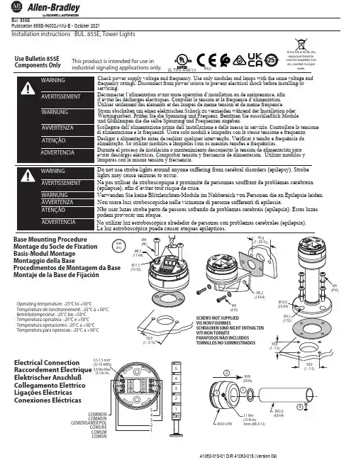
41063-015-01 DIR 41063-015 (Version 09)At the end of its life, this equipment should be collected separately from any unsorted municipalwaste.Publication 855E-IN002J-MU-E - October 2021Installation instructions BUL. 855E, Tower LightsBase Mounting Procedure Montage du Socle de FixationBasis-Modul Montage Montaggio della BaseProcedimentos de Montagem da Base Montaje de la Base de FijaciónUse Bulletin 855E Components Onlymm(in.)Electrical Connection Raccordement Electrique Elektrischer AnschlußCollegamento Elettrico Ligações Eléctricas Conexiones EléctricasCOMMON COMMUNGEMEINSAMER POLCOMUNE COMUM COMÚN4Operating temperature: -25°C to +50°CTempérature de fonctionnement: -25°C à +50°C Betriebstemperatur: -25°C bis +50°C Temperatura operativa: -25°C e +50°C Temperatura operaciones: -25°C a +50°C Temperatura para operacao: -25°C a +50°C1235Do not use strobe lights around anyone suffering from cerebral disorders (epilepsy). Strobe lights may cause seizures to occur.Ne pas utiliser de stroboscopique à proximité de personnes souffrant de problèmes cérébraux (épilepsie), afin d’éviter tout risque de crise.Verwenden Sie keine Blitzleuchten-Module im Nahbereich von Personen die an Epilepsie leiden.Non usare luci stroboscopiche nelle vicinanze di persone sofferenti di epilessia.Não usar luzes strobe perto de pessoas sofrendo de problemas cerebrais (epilepsia). Estas luzes podem provocar um ataque.No utilizar luz estroboscópica alrededor de personas con problemas cerebrales (epilepsia). La luz estroboscópica puede causar ataques epilépticos.Check power supply voltage and frequency. Use only modules and lamps with the same voltage and frequency ratings. Disconnect from power source to prevent electrical shock before installing or servicing.Déconnecter l’alimentation avant toute opération d’installation ou de maintenance, afin d’éviter les décharges électriques. Controler la tension et la fréquence d’alimentation. Utiliser seulement des éléments et des lampes de meme tension et de meme fréquence.Strom abschalten um einen elektrischen Schock zu vermeiden während der Installation oder Wartungsarbeit. Prüfen Sie die Spannung und Frequenz. Benützen Sie ausschließlich Module und Glühlampen die die selbe Spannung und Frequenzen angeben.Scollegare dall’alimentazione prima dell’installazione e della messa in servizio. Controllare la tensione di alimentazione e la frequenza. Usare solo moduli e lampadas con la stessa tensione e frequenza.Desligar a alimentação antes de realizar qualquer intervenção. Verificar a tensão e frequência da alimentação. Só utilizar módulos e lâmpadas com as mesmas tensões e frequências.Durante el proceso de instalación o mantenimiento desconectar la tensión de alimentación para evitar descargas eléctricas. Comprobar tensión y frecuencia de alimentación. Utilizar módulos y lámparas con la misma tensión y frecuencia.25UL TYPE 4/4X/13This product is intended for use in industrial signaling applications only.Installation instruction for BUL. 855E, Tower Lights2/241063-015-01DIR 41063-015 (Version 09 )Copyright © 2021 Rockwell Automation, Inc. All Rights Reserved. Printed in USA.Publication 855E-IN002J-MU-E - October 2021Product certificates are located in the Rockwell Automation Literature Library: rok.auto/certifications.Rockwell Automation maintains current product environmental compliance information on its website at rok.auto/pec.EEE Yönetmeliğine Uygundur .ASIA PACIFIC: Rockwell Automation, Level 14, Core F, Cyberport 3, 100 Cyberport Road, Hong Kong, Tel: (852) 2887 4788, Fax: (852) 2501846expanding human possibilityEUROPE/MIDDLE EAST/AFRICA: Rockwell Automation NV, Pegasus Park, De Kleetlan 12a, 1831 Diegem, Belgium, Tel: (32) 2663 0600, Fax: (32) 2663 0640AMERICAS: Rockwell Automation, 1201 South Second Street, Milwaukee, WI 53204-2496 USA, Tel: 414.382.2000, Fax: (1) 414.382.4444。
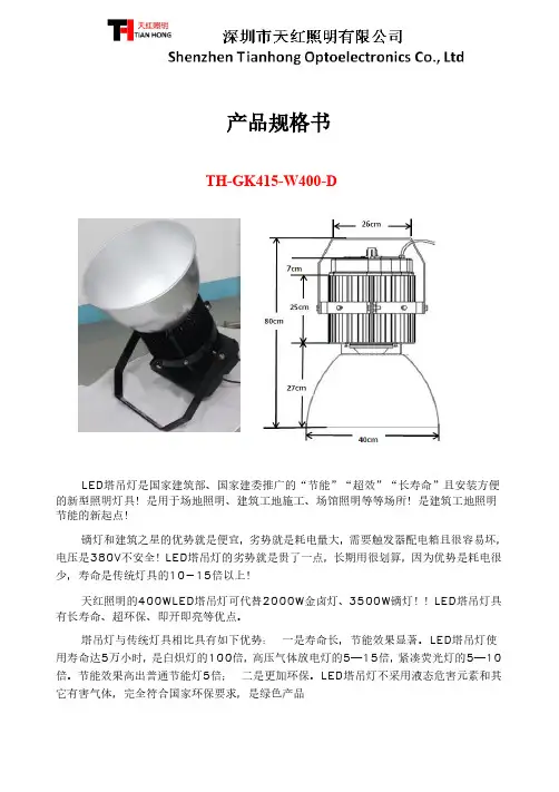
1号集体宿舍楼等3项(华北空管局值班宿舍(集体宿舍)工程))塔吊LED灯施工方案目录1. ............................................................................................................................ 编制依据.................................................................. 1…2 .工程概况............................................................. 1…2.1总体概况........................................................... 1…2.2设计概况........................................................... 2..3. LED灯及电缆选型、照明布置........................................... 2.4. LED灯组装........................................................... 3..4.1 LED灯安装平台 ..................................................... 3.4.2配电箱安装........................................................ 4..4.3配电箱的防护.......................................................5..4.4LED 灯安装.........................................................5..4.5电缆安装........................................................... 6..4.6塔吊顶升电缆的传递.................................................. 6. 5调试LED灯的调试与运行 ................................................ 7.5.1LED灯的调试....................................................... 7..5.2LED灯的运行....................................................... 7..6. LED灯拆除...........................................................7..6.1拆除安排...........................................................7..6.2拆除要求...........................................................7..7. LED灯的安全措施..................................................... 8..7.1LED灯安装安全要求................................................. 8.7.2作业人员的安全要求.................................................. 8.7.3施工现场值班电工职责................................................ 8.1号集体宿舍楼等3项(华北空管局值班宿舍(集体宿舍)工程))塔吊LED灯施工方案1.编制依据2. 工程概况2.1总体概况1号集体宿舍楼等3项(华北空管局值班宿舍(集体宿舍)工程))塔吊LED灯施工方案2.2设计概况3. LED灯及电缆选型、照明布置充分考虑LED灯覆盖面积、满足结构施工高度、方便LED灯的安装及维修的原则,对施工区LED灯及电缆进行选型。

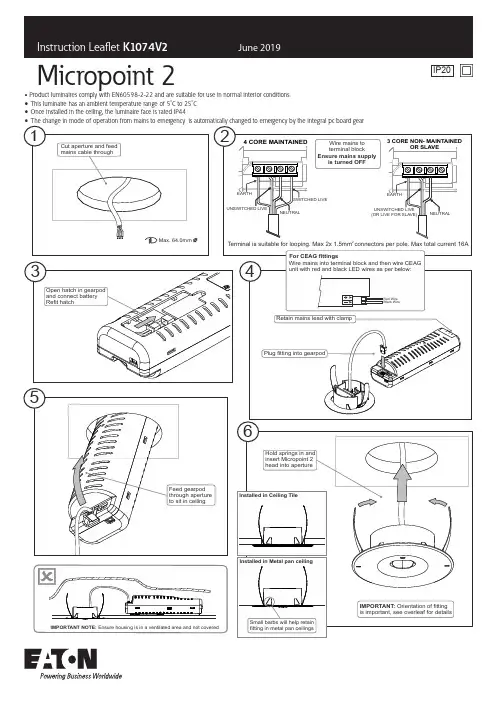
Micropoint 2Product luminaires comply with EN60598-2-22 and are suitable for use in normal interior conditions.o oThis luminaire has an ambient temperature range of 5C to 25COnce installed in the ceiling, the luminaire face is rated IP441. Check the rating label for voltage and frequency before connecting this luminaire to the electrical supply.2. Ensure that the mains supply is switched off when working on this luminaire, whether installing or carrying out any other servicing.3. Manual testing can be carried out by isolating the appropriate un-switched supply sub-circuit by use of a key operated switch.4. To prevent damage to driver, do not mix with conventional magnetic ballasts on the same electrical circuit.5. Where use in more onerous situations is required, e.g. In part-completed buildings before “drying-out” is completed, or areas where ambient temperatures are outside the normal temperature range, then consult our Sales Office.6. This product must only be installed in locations where accidental disconnection of the head interconnection lead is not possible.Servicing and Disposal1. At commissioning and handing over of installation ensure that a copy of these instructions is presented to the authority responsible for the operation and maintenance of the luminaries.2. Servicing, e.g. cleaning, must only be carried out after the electricity supply has been switched off. It must not be assumed that luminaries with lamps not lit are switched off-always check before servicing.3. Cleaning should be carried out at regular intervals to ensure that dirt does not accumulate to an extent that will impair the thermal safety or optical performance of the luminaire. Regular cleaning will also ensure that the optical performance of the luminaries is maintained.4. Avoid touching the LED array surface. To clean - Blow surface with either dry air or nitrogen gas.5. At the end of life the luminaire is classed as WEEE under directive 2012/19/EU and should be disposed of in accordance with local legislation.Note : The LED's are non-replaceable and the whole luminaire should be replaced at the end of life but the batteries can be replaced by a competent person and must be replaced when they no longer meet the rated duration.K1074V2EatonWheatley Hall Road, Doncaster, South Yorkshire, DN2 4NBSalesT: +44 (0)1302 303303 F: +44 (0)1302 367155 E:*******************General+44 (0)1302 321541+44 (0)1302 303220***********************International Sales+44 (0)1302 303250+44 (0)1302 303251********************Instruction Manual - K1074V2June 2019Micropoint 2。
本工程为塔吊亮化工程,位于XX市XX区XX项目工地。
工程主要包括塔吊及其基础周边的亮化照明设计、安装及调试。
亮化工程旨在美化施工现场,提高夜间施工安全性,同时展示工地文明施工形象。
二、施工组织设计1. 施工部署(1)成立项目组,明确各岗位人员职责,确保施工顺利进行。
(2)制定详细的施工方案,明确施工流程、施工工艺、质量标准、安全措施等。
(3)合理安排施工进度,确保工程按时完成。
2. 施工平面布置(1)塔吊基础周边设置亮化照明设施,包括投光灯、轮廓灯、地埋灯等。
(2)照明设施布置合理,确保施工现场亮化效果。
3. 施工进度计划(1)施工前,对施工人员进行技术培训和安全教育。
(2)根据施工方案,制定详细的施工进度计划,确保工程按时完成。
三、施工工艺及质量控制1. 施工工艺(1)塔吊基础周边亮化照明设施安装:①根据设计要求,确定照明设施的位置和高度。
②采用专业工具和设备进行安装,确保照明设施牢固可靠。
③安装完成后,对照明设施进行调试,确保其正常工作。
(2)投光灯安装:①根据设计要求,确定投光灯的位置和角度。
②使用专用工具将投光灯固定在支架上。
③调试投光灯,确保其光束覆盖范围符合设计要求。
2. 质量控制(1)严格按照设计要求和施工规范进行施工。
(2)加强施工过程中的质量检查,确保施工质量。
(3)对安装完成的照明设施进行验收,确保其符合设计要求。
四、安全措施1. 施工人员必须佩戴安全帽、安全带等防护用品。
2. 施工现场设置警示标志,确保施工安全。
3. 施工过程中,严格执行安全操作规程,防止安全事故发生。
4. 施工结束后,对施工现场进行清理,确保无安全隐患。
五、施工进度保证措施1. 合理安排施工人员,确保施工力量充足。
2. 加强施工过程中的协调沟通,确保施工进度。
3. 严格按照施工进度计划执行,确保工程按时完成。
4. 对施工过程中遇到的问题,及时解决,确保施工进度不受影响。
六、工程验收1. 施工完成后,对工程进行自检,确保工程质量。
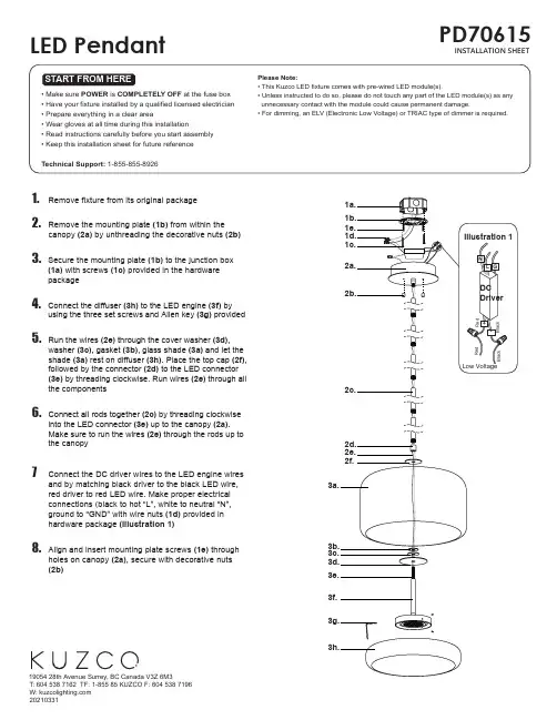
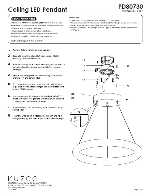
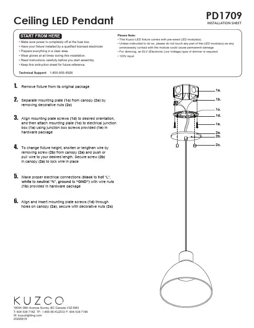
1. Remove fixture from its original package2.Separate mounting plate (1c) from canopy (2a) byremoving canopy screws (2b)3.Attach mounting plate (1c) to electrical junction box (1a) using junction box screws provided (1e) in hardware package4. Secure mounting plate (1c) to mounting surface withanchors (1f) and screws (1g)5.To change fixture height, push and hold wire gripper (2g), slide wire to desired length and then release wire gripper (2g) to secure6.Make proper electrical connections (black to hot “L”,white to neutral “N”, ground to “GND”) with wire nuts(1b) provided in hardware package7.Attach canopy (2a) to mounting plate (1c) with canopy screws (2b)8.Fine tone wire length if necessary, by push and holdwire gripper (2g) and then adjust wire to desired lengthFOR ALTERNATIVE SIDE CANOPY INSTALLNote:17-3/8” and 10”1.Disconnect output wires on driver (4a)2.Separate wire gripper (2g) from canopy (2a) by removing nut and tooth washer (6a). Separate plug (6b) from canopy (2a) by removing nut, tooth washer and flat washer (6c)(See Illustration 1)3.Feed fixture wires through centre hole on canopy plate(7a), canopy (2a), t ooth washer and nut (5a). Attachcanopy plate (7a) to canopy (2a), followed by wire gripper (2g) and secure with tooth washer and nut (5a) (See Illustration 2)4. Make proper electrical connections between LED and DC driver, LED- Negative, LED+ Positive using wago connector (4b) provided driver)5.Make proper electrical connections (black to hot “L”, white to neutral “N”, ground to “GND”) with wire nuts(1b) provided in hardware package6. Attach canopy (2a) to mounting plate (1c) with canopy screws (2b). Position desired amount of wire by pushing gripper (2g) on canopy7.Pull wire through aircraft barrel (3b) and stopper (3d).Secure aircraft barrel (3b) (3c) and screw (3a). Adjust wire to desired length and secure with set screw (3e). Insert wire gripper (2g) intoaircraft barrel (3b) to close 8.Fine tone wire length if necessary, by push and holdwire gripper (2g) and then adjust wire to desired length。
第1篇一、工程概况1. 工程名称:XX项目灯具安装设计工程2. 工程地点:XX市XX区XX路XX号3. 工程规模:本项目总建筑面积为XX万平方米,共XX栋楼,包括住宅、商业、办公等不同功能区域。
4. 工程业主:XX房地产开发有限公司5. 设计单位:XX建筑设计研究院二、设计依据1. 国家现行相关标准、规范和法规2. 业主提供的设计图纸和工程资料3. 设计单位内部技术文件和管理制度三、设计原则1. 安全可靠:确保灯具安装质量和使用安全,符合国家相关安全标准。
2. 节能环保:采用节能灯具,降低能耗,减少环境污染。
3. 经济合理:在满足功能需求的前提下,尽量降低工程造价。
4. 美观大方:灯具造型与建筑风格相协调,营造舒适、美观的室内外环境。
四、灯具安装设计要求1. 室内灯具安装设计(1)光源选择:根据不同功能区域,选择合适的照明光源,如LED、荧光灯、卤素灯等。
(2)灯具类型:根据室内空间特点,选择合适的灯具类型,如吊灯、壁灯、落地灯、吸顶灯等。
(3)照明方式:采用多种照明方式相结合,如直接照明、间接照明、混合照明等,以满足不同区域的功能需求。
(4)照度要求:根据国家相关标准,确定室内各区域的照度值,确保照明效果。
(5)灯具间距:根据灯具类型和照度要求,合理确定灯具间距,保证照明效果。
2. 室外灯具安装设计(1)光源选择:采用节能、长寿命的光源,如LED、高压钠灯等。
(2)灯具类型:根据室外环境特点,选择合适的灯具类型,如路灯、庭院灯、草坪灯、景观灯等。
(3)照明方式:采用均匀照明,确保道路、广场、景观等区域的照明效果。
(4)照度要求:根据国家相关标准,确定室外各区域的照度值,保证照明效果。
(5)灯具间距:根据灯具类型和照度要求,合理确定灯具间距,保证照明效果。
五、施工要求1. 施工前,施工单位应熟悉设计图纸,明确灯具安装设计要求。
2. 施工现场应保持整洁,施工人员应遵守施工现场安全规定。
3. 施工过程中,严格遵循施工规范和操作规程,确保灯具安装质量。
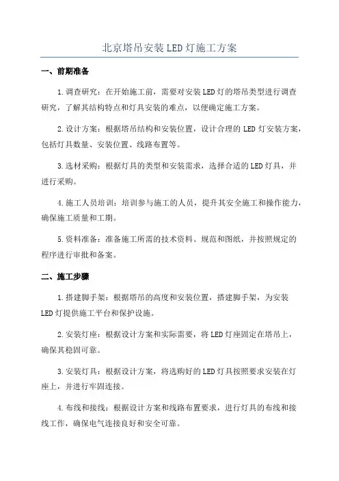
北京塔吊安装LED灯施工方案一、前期准备1.调查研究:在开始施工前,需要对安装LED灯的塔吊类型进行调查研究,了解其结构特点和灯具安装的难点,以便确定施工方案。
2.设计方案:根据塔吊结构和安装位置,设计合理的LED灯安装方案,包括灯具数量、安装位置、线路布置等。
3.选材采购:根据灯具的类型和安装需求,选择合适的LED灯具,并进行采购。
4.施工人员培训:培训参与施工的人员,提升其安全施工和操作能力,确保施工质量和工期。
5.资料准备:准备施工所需的技术资料、规范和图纸,并按照规定的程序进行审批和备案。
二、施工步骤1.搭建脚手架:根据塔吊的高度和安装位置,搭建脚手架,为安装LED灯提供施工平台和保护设施。
2.安装灯座:根据设计方案和实际需要,将LED灯座固定在塔吊上,确保其稳固可靠。
3.安装灯具:根据设计方案,将选购好的LED灯具按照要求安装在灯座上,并进行牢固连接。
4.布线和接线:根据设计方案和线路布置要求,进行灯具的布线和接线工作,确保电气连接良好和安全可靠。
5.调试和测试:完成灯具的安装后,进行灯具的调试和测试工作,确保其亮度、色温、均匀度等指标符合要求。
6.安全防护:在安装完LED灯后,对整个安装区域进行安全防护工作,如设置警示标志、警示灯和防护网等。
7.清理和整理:完成安装工作后,对施工区域进行清理和整理,保持工地环境整洁。
三、安全措施1.专人负责:指定一位专人负责塔吊安装LED灯的施工工作,统筹协调各个环节,确保施工顺利进行。
2.安全防护:在施工现场设立安全警示标识、警示灯和防护网,设置注意事项和警示标语,提醒施工人员注意安全。
3.制定操作程序:制定塔吊安装LED灯的操作程序,明确工作内容、工作要点、注意事项和安全措施,确保施工过程中的安全。
4.个人防护用具:配备施工人员必需的个人防护用具,如安全帽、防护眼镜、防护手套、防护鞋等。
5.定期检查:定期对已安装的LED灯进行检查和维护,确保其正常运行和使用寿命。
灯具安装说明书一、安装前的准备工作在进行灯具安装之前,您需要做一些准备工作。
首先,请确保您已经购买到了适合您需求的灯具,并检查包装中是否包含了所有安装所需的零件和配件。
若有缺少或损坏的零件,请您立即与销售商联系。
二、工具和材料为了完成灯具的安装,您还需要以下工具和材料:1. 打孔器或螺丝刀:用于固定灯具支架或装饰盖板。
2. 电钻或电动螺丝刀:用于固定灯具支架或灯泡底座。
3. 电线切割钳:用于剪断电线并进行连接。
4. 绝缘胶带:用于绝缘电线连接处。
5. 手套和安全眼镜:用于安全工作。
三、安装步骤1. 关闭电源:在进行任何安装或维修前,请确保关闭电源开关,并确认灯具上的电源已经切断。
2. 定位支架:根据您的需要,使用打孔器或螺丝刀在天花板上打孔,并安装灯具支架。
请确保支架安装坚固可靠。
3. 连接电线:使用电线切割钳将灯具的电线与电源线连接起来。
请确保使用绝缘胶带正确绝缘连接处。
4. 固定灯具底座:根据灯具的类型和设计,使用电钻或电动螺丝刀将灯具底座牢固地固定在支架上。
5. 安装灯泡:根据灯具的说明书,将灯泡安装到灯具底座上。
请注意选择合适的灯泡类型和功率。
6. 测试灯具:在打开电源开关之前,请确保灯具已安装妥当。
您可以进行一次简单的测试,确认灯具可以正常工作。
7. 安装装饰盖板:如果您的灯具配备了装饰盖板,根据说明书的指示,将其安装在灯具上。
切记不要过紧,以免损坏灯具。
深入分析和额外说明:在灯具安装过程中,请注意以下几点:1. 安装位置:根据您的需要和灯具类型,选择合适的安装位置。
例如,台灯适合放置在工作台或床头柜上,吊灯适合用于餐厅或客厅的顶棚装饰。
2. 安全事项:在进行灯具安装之前,请确保电源已经关闭,以避免电击。
同时,佩戴手套和安全眼镜,以保护您的身体免受潜在的危险。
3. 电线连接:在连接电线时,请确保正确地匹配颜色,即将相同颜色的电线连接在一起。
例如,蓝色电线连接到蓝色电线,棕色电线连接到棕色电线。
Page 1©2010 Whelen Engineering Company Inc.Form No.14413A (012216)Installation Guide:Pioneer™ Series LED Floodlight115 Volts AC Pedestal Mount51 Winthrop RoadChester, Connecticut 06412-0684Phone: (860) 526-9504Internet: Sales e-mail: autosale@Customer Service e-mail: custserv@®ENGINEERING COMPANY INC.For warranty information regarding this product, visit /warranty•Proper installation of this product requires the installer to have a good understanding of automotive electronics, systems and procedures.•Whelen Engineering requires the use of waterproof butt splices and/or connectors if that connector could be exposed to moisture.•Any holes, either created or utilized by this product, should be made both air- and watertight using a sealant recommended by your vehicle manufacturer.•Failure to use specified installation parts and/or hardware will void the product warranty.•If mounting this product requires drilling holes, the installer MUST be sure that no vehicle components or other vital parts could be damaged by the drilling process. Check both sides of the mounting surface before drilling begins. Also de-burr the holes and remove any metal shards or remnants. Install grommets into all wire passage holes.•If this manual states that this product may be mounted with suction cups, magnets, tape or Velcro®, clean the mounting surface with a 50/50 mix of isopropyl alcohol and water and dry thoroughly.•Do not install this product or route any wires in the deployment area of your air bag. Equipment mounted or located in the air bag deployment area will damage or reduce the effectiveness of the air bag, or become a projectile that could cause serious personal injury or death. Refer to your vehicle owner’s manual for the air bag deployment area. The User/Installer assumes full responsibility to determine proper mounting location, based on providing ultimate safety to all passengers inside the vehicle.•For this product to operate at optimum efficiency, a good electrical connection to chassis ground must be made. The recommendedprocedure requires the product ground wire to be connected directly to the NEGATIVE (-) battery post (this does not include products that use cigar power cords).•If this product uses a remote device for activation or control, make sure that this device is located in an area that allows both the vehicle and the device to be operated safely in any driving condition.•Do not attempt to activate or control this device in a hazardous driving situation.•This product contains either strobe light(s), halogen light(s), high-intensity LEDs or a combination of these lights. Do not stare directly into these lights. Momentary blindness and/or eye damage could result.•Use only soap and water to clean the outer lens. Use of other chemicals could result in premature lens cracking (crazing) and discoloration. Lenses in this condition have significantly reduced effectiveness and should be replaced immediately. Inspect and operate this product regularly to confirm its proper operation and mounting condition. Do not use a pressure washer to clean this product.•It is recommended that these instructions be stored in a safe place and referred to when performing maintenance and/or reinstallation of this product.•FAILURE TO FOLLOW THESE SAFETY PRECAUTIONS AND INSTRUCTIONS COULD RESULT IN DAMAGE TO THE PRODUCT OR VEHICLE AND/OR SERIOUS INJURY TO YOU AND YOUR PASSENGERS!A u t o m o t i v e : L i g h t h e a d sWarnings to InstallersWhelen’s emergency vehicle warning devices must be properly mounted and wired in order to be effective and safe. Read and follow all of Whelen’s written instructions when installing or using this device. Emergency vehicles are often operated under high speed stressful conditions which must be accounted for when installing all emergency warning devices. Controls should be placed within convenient reach of the operator so that they can operate the system without taking their eyes off the roadway. Emergency warning devices can require high electrical voltages and/or currents. Properly protect and use caution around live electrical connections.Grounding or shorting of electrical connections can cause high current arcing, which can cause personal injury and/or vehicle damage, including fire. Many electronic devices used in emergency vehicles can create or be affected by electromagnetic interference. Therefore, after installation of any electronic device it is necessary to test all electronic equipment simultaneously to insure that they operate free of interference from other components within the vehicle. Never power emergency warning equipment from the same circuit or share the same grounding circuit with radio communication equipment. All devices should be mounted in accordance with the manufacturer’s instructions and securely fastened to vehicle elements of sufficient strength to withstand the forces applied to the device. Driver and/or passenger air bags (SRS) will affect the way equipment should be mounted. This device should be mounted by permanent installation and within the zones specified by the vehicle manufacturer, if any. Any device mounted in the deployment area of an air bag will damage or reduce the effectiveness of the air bag and may damage or dislodge the device. Installer must be sure that this device, its mounting hardware and electrical supply wiring does not interfere with the air bag or the SRS wiring or sensors. Mounting the unit inside the vehicle by a method other than permanent installation is not recommended as unit may become dislodged during swerving; sudden braking or collision. Failure to follow instructions can result in personal injury. Whelen assumes no liability for any loss resulting from the use of this warning device. PROPER INSTALLATION COMBINED WITH OPERATOR TRAINING IN THE PROPER USE OF EMERGENCY WARNING DEVICES IS ESSENTIAL TO INSURE THE SAFETY OF EMERGENCY PERSONNEL AND THE PUBLIC.Warnings to UsersWhelen’s emergency vehicle warning devices are intended to alert other operators and pedestrians to the presence and operation of emergency vehicles and personnel. However, the use of this or any other Whelen emergency warning device does not guarantee that you will have the right-of-way or that other drivers and pedestrians will properly heed an emergency warning signal. Never assume you have the right-of-way. It is your responsibility to proceed safely before entering an intersection, driving against traffic, responding at a high rate of speed, or walking on or around traffic lanes. Emergency vehicle warning devices should be tested on a daily basis to ensure that they operate properly. When in actual use, the operator must ensure that both visual and audible warnings are not blocked by vehicle components (i.e.: open trunks or compartment doors), people, vehicles, or other obstructions. It is the user’s responsibility to understand and obey all laws regarding emergency warning devices. The user should be familiar with all applicable laws and regulations prior to the use of any emergency vehicle warning device. Whelen’s audible warning devices are designed to project sound in a forward direction away from the vehicle occupants. However, because sustained periodic exposure to loud sounds can cause hearing loss, all audible warning devices should be installed and operated in accordance with the standards established by the National Fire Protection Association.Safety FirstThis document provides all the necessary information to allow your Whelen product to be properly and safely installed. Before beginning the installation and/or operation of your new product, the installation technician and operator must read this manual completely. Important information is contained herein that could prevent serious injury or damage.Mounting...1.Position the Flange Base (#12) onto the proposed mounting surface. Mark theareas where the mounting holes are to be drilled.2.Drill the mounting holes required using an appropriately sized drill bit (refer to theFlange Base Mounting Information shown below).3.Slide an O-Ring (#17) onto the Pivot Pin (#13) until it reaches the base. Insert thePivot Pin up through the bottom of the Flange Base and position the Flange Base/ Pivot Pin assembly onto the mounting surface. Secure the Flange Base to the mounting surface using the hardware provided (#11, #14, #15 & #16).4.Slide the remaining O-Ring (#17) onto the Pivot Pin. Thread the Clamp Nut Collar(#18) into the Pivot Pin. Do not tighten this collar yet. Place the Pivot Arm (#19) onto the Pivot Pin so that the tapped holes are aligned with the dimples on the Pivot Pin.5.Insert a Socket Set Screw (#10) into each of the two tapped holes in the PivotArm. Tighten to secure to the Pivot Pin.6.Attach the appropriate pole mount bracket (#3 or #4) onto the Pioneer using thehardware provided (#2). Apply a drop of LocTite®242 or equivalent to the threads.7.Secure the Handle (#1) onto the Pole Mount Bracket using the hardare provided(#5).8.Install the Pivot Bracket (#22) onto the pole mount bracket studs and firmly secureusing the hardware provided (#6, #7 & #8).9.Insert the Pioneer/Pivot Bracket assembly into the receiving cup of the Pivot Arm.Insert the Hex Bolt (#9) through the Pivot Bracket and Pivot arm. Install the internal tooth lockwasher (#21) and the Knob (#20) onto this hex bolt.10.When the Pioneer has been adjusted to the desired angle and rotation, tighten theKnob and Collar firmly to maintain that angle.Wiring...All components, equipment and installation procedures shall conform to NFPA 1901, Standard For Automotive Fire Apparatus and NFPA National Electical Code.•Make sure that power is OFF before connecting any wires to the power source!•Make sure that the power source used features an appropriately sized circuit protection device!•If necessary, extend lighthead wires using minimum 16 AWG wire.Refer to the wiring guide included with your Pioneer for wire functions, fuse values and optional switch connections.Product Specifications...Operating Voltage. . . . . . . . . . . . . . . . . . 115VAC / 60HzWatts / Amps (Pioneer Single). . . . . . . . . 75W / 0.625AWatts / Amps (Pioneer Dual) . . . . . . . . . . .150W / 1.25AIMPORTANT! Before returning the vehicle to active service, visually confirm the proper operation of this product, as well as all vehicle components/ equipment.。