红外温度传感器OTP-538U
- 格式:doc
- 大小:441.00 KB
- 文档页数:7
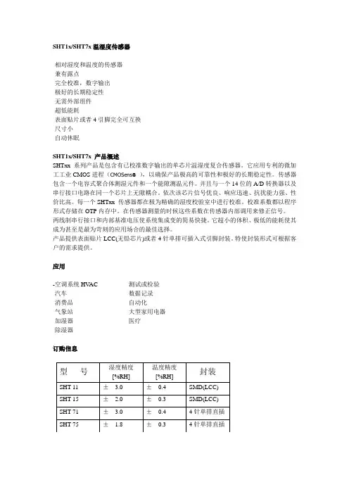
SHT1x/SHT7x温湿度传感器-相对湿度和温度的传感器-兼有露点-完全校准,数字输出-极好的长期稳定性-无需外部组件-超低能耗-表面贴片或者4引脚完全可互换-尺寸小-自动休眠SHT1x/SHT7x 产品概述SHTxx 系列产品是包含有已校准数字输出的单芯片温湿度复合传感器。
它应用专利的微加工工业CMOS进程(CMOSens®),以确保产品极高的可靠性和极好的长期稳定性。
传感器包含一个电容式聚合体测湿元件和一个能隙测温元件。
并且与一个14位的A/D转换器以及串行接口电路在同一个芯片上无隙耦合。
依次该芯片信号优良、响应迅速、抗扰能力强、性价比高。
每一个SHTxx 传感器都在极为精确的湿度校验室中进行校准。
校准系数都以程序形式存储在OTP内存中。
在传感器测量的时候这些系数在传感器内部调用来修正信号。
两线制串行接口和内部基准电压使系统集成变的简易快捷。
它超小的体积、极低的能耗使其成为甚至是最为苛刻的应用场合的最佳选择。
产品提供表面贴片LCC(无铅芯片)或者4针单排可插入式引脚封装。
特使封装形式可根据客户的需求提供。
应用-空调系统HV AC -测试或检验-汽车-数据记录-消费品-自动化-气象站-大型家用电器-加湿器-医疗-除湿器订购信息型号湿度精度[%RH] 温度精度[%RH]封装SHT 11 ± 3.0 ±0.4 SMD(LCC) SHT 15 ± 2.0±0.3 SMD(LCC) SHT 71 ± 3.0 ±0.4 4针单排直插SHT 75 ± 1.8 ±0.3 4针单排直插1 传感器性能说明参数条件最小典型值最大单位湿度分辨率0.5 0.03 0.03 %RH8 12 12 bit重复性± 0.1%RH线性化见图一精度不确定性互换性完全可互换非线性度原始数据± 3%RH线性化<<1 %RH范围0 100 %RH响应时间1/e(63%)4 S缓慢流动的空气迟滞± 1%RH长期稳定性典型值<0.5 %RH/yr温度分辨率0.04 0.01 0.01 ℃0.07 0.02 0.02 °F12 14 14 bit重复性± 0.1℃± 0.2°F精确度见图一范围-40 123.8 ℃-40 254.9 °F响应时间1/e(63%) 5 30 S表1 传感器性能说明2 接口说明2.1 电源引脚SHTxx的供电电压在2.4 - 5.5V.上电后,传感器需要11ms月过期“休眠”状态。

传感与检测技术一、题目:农用烘干机温度检测系统二、背景意义目的1、选题的背景:智能传感器是一门涉及多种学科的综合技术,是当今社会正在发展中的高新技术,被广泛地应用于军事、航天航空、科研、工业、农业、医疗、交通等领域和部门,具有十分广阔的应用前景。
温度传感器有特色的经济类粮食烘干过程中测量的主要参数是水分含量,但是温度的测量也不可忽略,温度过低,达不到烘干要求,温度过高,则会烧坏粮食。
因此,改善粮食烘干塔的温度水分检测系统具有重要的社会意义和经济意义。
2、意义:干燥的目的是为了物料使用或进一步加工的需要。
如木材在制作木模、木器前的干燥可以防止制品变形,陶瓷坯料在煅烧前的干燥可以防止成品龟裂。
另外干燥后的物料也便于运输和贮存,如将收获的粮食干燥到一定湿含量以下,以防霉变。
由于自然干燥远不能满足生产发展的需要,各种机械化干燥机越来越广泛地得到应用。
3、目的:提高经济效益、提高粮食品质、降低劳动强度三、设计方案1、方框图2、各部分组成及功能温度传感器:OTP-538U红外传感器,在5-14μm的红外波长范围内能进行温度测量放大电路:功率放大器AD620。
OTP-538U正常工作时,输出电压仅仅为几毫伏,主要集中在-1.4~5.0mV之间,如此低的电压难以被控制器检测。
因此需要在传感器电路中增加功率放大器滤波电路:有限增益压控压控型滤波器,低通滤波器(LPF),粮食烘干机温度检测系统中,且环境周围干扰信号绝大多数为高频信号,故此需要设计滤波电路。
四、选型依据及输入输出关系1、传感器选型:OTP-538,红外模拟式温度传感器2、依据:根据粮食(如木耳,水稻,玉米),木材等农作物烘干温度要求:系统温度测量范围定为:0℃-100℃;在测量范围内传感器线性度要求:δ<10%;温度误差为:±0.2C;根据以上要求,选择OTP-538U红外传感器作为温度传感器,OTP-538U 传感器采用电压输出,通过测量电压即可得知其温度值。
![[中学教育]红外温度传感器OTP-538U](https://uimg.taocdn.com/96bf05feb9f67c1cfad6195f312b3169a451ea3b.webp)
IntroductionThe OTP-538U is a thermopile sensor in classic TO-46 housing. The sensor is composed of 116 elements of thermocouple in series on a floating micro-membrane having an active diameter of 545 μm and with blacken surface to absorb the incident thermal infrared radiation, which induces a voltage response at output terminals. The sensor chip is fabricated by a unique front-surface bulk micromachining technology, which result in smaller size and faster to response ambient temperature change.The IR window is a bandpass filter having its 50% cut -on wavelength at 5 μm, and cut -down at 14μm. The sensor responses proportionally to the incident IR radiation and has a constant signal response up to its cut-off frequency, which is limited by the sensor thermal time constant of tens millisecond range.The OTP-538U thermopile sensor provides nearly Johnson-noise-limited performance, which canbe calculated by its ohmic series resistance. A thermistor element, with a lead connected to ground, is also provided inside the TO package for ambient temperature reference .FeaturesNon-contact temperature detection Voltage output, easy to take signalZero power consumptionWide detection temperature rangeApplicationsMedical Application: Ear thermometersHome Facility: Microwave oven, Hair dryer, Safety system, Home security, Refrigerator & AirconditionerIndustry Application: Process monitor and controller, Infrared non-contact thermometersAutomobile Application: Thermal sensing systemTable of Contents1 General Characteristics1.1 Absolute Maximum Ratings1.2 Handling Guidelines2 Device Characteristics2.1 Device Descriptions2.2 Sensor Characteristics2.3 Signal Output Characteristics2.4 Frequency Response2.5 Thermistor Characteristics 2.6 Optical Characteristics2.7 Filter Characteristics2.8 Mechanic Drawing and Pin Assignment3 Liability StatementList of FiguresFigure 1: Typical output voltage versus object temperature with sensor at 25° CFigure 2: Frequency responseThermopile Sensor OTP-538URevision Date: 2009/04/16Figure 3: Field of view curveFigure 4: Typical spectral transmittance curveFigure 5: Mechanical drawing and pin assignmentList of TablesTable 1: Absolute maximum ratingsTable 2: Device characteristicsTable 3: Thermopile sensor characteristicsTable 4: Typical numerica l data of Thermopile’s output voltage (sensor at 25° C)Table 5: Thermistor informationTable 6: Tabulated thermistor dataTable 7: Optical characteristicsTable 8: Filter parameters1. General Characteristics1.1 Absolute Maximum Rating1.2 Handling GuidelinesStresses above the absolute maximum ratings may cause damages to the device.Do not expose the sensor to aggressive detergents such as Freon, Trichloroethylene, etc.Avoid touching or cleaning of the window. If necessary, do cleaning only very carefully with alcohol andcotton swab.Hand soldering and wave soldering may be applied by a maximum temper ature of 260° C for a dwell timeless than 10 s. Reflow soldering is not recommended.2. Device Characteristics2.1 Device DescriptionsThe materials of OTP-538U are lead-free and fully complied with the RoHS regulations.2.2 Sensor CharacteristicsNotes: * All optical performances are measured at 1 Hz chopper frequency using a blackbody radiator of 500K temperature with filtered spectrum ranging from 5 to 14 μm.Distance between packaged thermopile and blackbody is 11cm.2.3 Signal Output Characteristics3. Liability StatementThe contents of this document are subject to change without notice and customers should consult withOriental System Technology (OST) sales representatives before ordering. Customers considering the use ofOST thermopile devices in applications where failure may cause personal injury or property damage, or where extremely high levels of reliability are demanded, are requested to discuss their concerns with OST sales representatives before such use. The Company’s responsibility for damages will be limited to the repair or replacement of defective product. As with any semiconductor device, thermopile sensors or modules have a certain inherent rate of failure. To protect against injury, damage or loss from such failures, customers are advised to incorporate appropriate safety design measures into their product.。
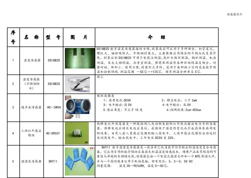
序号名称型号图片介绍1温度传感器DS18B20DS18B20数字温度传感器接线方便,封装成后可应用于多种场合,如管道式,螺纹式,磁铁吸附式,不锈钢封装式。
主要根据应用场合的不同而改变其外观。
封装后的DS18B20可用于电缆沟测温,高炉水循环测温,锅炉测温,机房测温,农业大棚测温,洁净室测温,弹药库测温等各种非极限温度场合。
耐磨耐碰,体积小,使用方便,封装形式多样,适用于各种狭小空间设备数字测温和控制领域.测温范围-55℃~+125℃,固有测温分辨率0.5℃.2温度传感器(不锈钢防水)DS18B20同上3超声波传感器HC—SR04模块高精度1:使用电压:DC5V 2:静态电流:小于2mA3:电平输出:高5V 4:电平输出:底0V5:感应角度:不大于15度6:探测距离:2cm-450cm4人体红外感应模块HC-SR501热释电红外传感器是一种能检测人或动物发射的红外线而输出电信号的传感器。
热释电效应同压电效应类似,是指由于温度的变化而引起晶体表面荷电的现象。
当有人进入其感应范围则输入高电平,人离开感应范围则自动延时关闭高电平。
输出低电平。
工作电压DC5V至20V。
DHT11数字温湿度传感器是一款含有已校准数字信号输出的温湿度复合传感6霍尔开关传感器A3144E霍尔传感器应用霍尔效应原理,采用半导体集成技术制造的磁敏电路,它是由电压调整器、霍尔电压发生器、差分放大器、史密特触发器,温度补偿电路和集电极开路的输出级组成的磁敏传感电路,其输入为磁感应强度,输出是一个数字电压信号。
产品特点:体积小、灵敏度高、响应速度快、温度性能好、精确度高、可靠性高。
典型应用:无触点开关、汽车点火器、刹车电路、位置、转速检测与控制、安全报警装置、纺织控制系统.7反射式光电传感器ST188RRP220根据反射式红外光电传感器的原理和内部结构,我们可以设计上面的电路,电阻主要起限流作用,电阻值常设置为:R1=510Ω,R2=20kΩ。
Rev.C1AT4708H~64H多路温度测试仪AT4708H~64H 用户手册2有限担保和责任范围3 3声明根据国际版权法,未经常州安柏精密仪器有限公司(Applent Instruments Inc.)事先允许和书面同意,不得以任何形式复制本文内容。
安全信息为避免可能的电击和人身安全,请遵循以下指南进行操作。
免责声明用户在开始使用仪器前请仔细阅读以下安全信息,对于用户由于未遵守下列条款而造成的人身安全和财产损失,安柏仪器将不承担任何责任。
仪器接地为防止电击危险,请连接好电源地线。
不可在爆炸性气体环境使用仪器不可在易燃易爆气体、蒸汽或多灰尘的环境下使用仪器。
在此类环境使用任何电子设备,都是对人身安全的冒险。
不可打开仪器外壳非专业维护人员不可打开仪器外壳,以试图维修仪器。
仪器在关机后一段时间内仍存在未释放干净的电荷,这可能对人身造成电击危险。
不要使用工作异常的仪器如果仪器工作不正常,其危险不可预知,请断开电源线,不可再使用,也不要试图自行维修。
不要超出本说明书指定的方式使用仪器超出范围,仪器所提供的保护措施将失效。
警告:不要加超过2000V的直流电压或超过1400V的交流电压到测试端,否则会损坏仪器。
安全标志:设备由双重绝缘或加强绝缘保护废弃电气和电子设备(WEEE) 指令2002/96/EC切勿丢弃在垃圾桶内4有限担保和责任范围5 5有限担保和责任范围常州安柏精密仪器有限公司(以下简称安柏)保证您购买的每一台仪器在质量和计量上都是完全合格的。
此项保证不包括保险丝以及因疏忽、误用、污染、意外或非正常状况使用造成的损坏。
本项保证仅适用于原购买者,并且不可转让。
自发货之日起,安柏提供贰年免费保修,此保证也包括VFD或LCD。
保修期内由于使用者操作不当而引起仪器损坏,维修费用由用户承担。
贰年后直到仪表终生,安柏将以收费方式提供维修。
对于VFD或LCD的更换,其费用以当前成本价格收取。
如发现产品损坏,请和安柏取得联系以取得同意退回或更换的信息。
智能多路温度检测系统中国科学院感光化学研究所陶培德摘要本文详细地介绍了八路温度巡回检测/定点检测系统的硬件配置、误差分析和软件设计方法。
该系统特点有三:①采用铂热电阻测温,布线为三线制,不加补偿电阻,从电路模型中消除了连接导线电阻引进的测量误差。
②八路测温用用一套温度?电压变换电路,测温点间的切换采用廉价的CD4051八选一模拟开关,其开关的导通电阻及导通电阻路差均布引进测量误差。
③铂热电阻温度/电压变换电路的非线性由硬件电路校正,校正后的非线性误差在0~199.9℃范围内小于0.0045%。
整个系统采用89S51单片机控制键盘操作,实现检测温度的实时显示、打印、越线报警功能。
引言温度的精密测量是工业生产领域中的一个经典课题。
在温度检测系统中,测量变换电路起着至关重要的作用,而温度传感器又是该电路中的一个关键元件。
众所周知,在设计测量变换电路时,我们是从分析传感器性能(电阻型、电流型、电压型等)入手,通过适当的补偿、非线性校正及信号放大环节,最后综合处一个满足期望指标的测量变换电路来。
目前,使用比较广泛的温度传感器有四类:热电阻(如铂热电阻)、热电偶、热敏电阻及集成电路温度传感器(如AD590)。
本文介绍的检测系统,采用铂热电阻(以下简称铂电阻)元件测温。
铂电阻温度传感器具有精度高、性能稳定、互换性好(有分度表)、耐腐蚀及使用方便等一系列有点,移植是工业测控系统中广泛使用的一种比较理想的测温元件。
在温度大于0℃的条件下,铂电阻的电阻值R(t)与被测温度t之间呈如下关系:R(t)R(0)?(1+At+Bt2) (1)式中(对BA2分度号而言)R(0)100Ω(0℃时的电阻值)A3.96847×10-3/℃(一次温度系统数)B?5.847×10-7/℃2(二次温度系统数)由式(1)可见,铂电阻的不足之处是:温度比较率小(α≈0.391Ω/℃),存在Bt2二次飞线性项。
大家知道,铂电阻作为温度传感器使用时,必须把它放在测温现场。
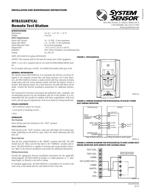
1 I56-0758-016 06-10SPECIFICATIONS Dimensions: 4.6˝ H × 2.75˝ W × 1.8˝ D Weight:0.24 Lbs.Power Requirements Power LED (Green): 14 – 35 VDC, 12 mA maximum Alarm LED (Red): 2.8 – 32 VDC, 12 mA maximum Alarm Response Time: 40 seconds maximumT emperature: –10°C to 60°C (14°F to 140°F)Humidity: 95% relative humidity, noncondensing Max Listing:UL, FM, CERTS151KEY(A)Remote Test StationINSTALLATION AND MAINTENANCE INSTRUCTIONSI56-0758-0163825 Ohio Avenue, St. Charles, Illinois 601741.800.SENSOR2; Fax: 630.377.6495NOTE: RTS151KEY(A) replaces RTS451KEY .NOTICE: This manual shall be left with the owner/user of this equipment.NOTE: A test coil is required only for use with D2/DNR/DH400/DH500 mod-els.For D2 models order part # DCOIL. For DH400/500 models order part #Coil.GENERAL INFORMATIONThe System Sensor RTS151KEY(A) is an automatic fire detector accessory de-signed to test remotely located duct and beam detectors. For 4-wire detec-tors, the RTS151KEY(A) features a multi-colored LED that alternates between steady green and red. Green indicates power and that the detector board is in place. Red indicates alarm. For 2-wire detectors, the LED will show red for alarm. Consult the detector installation instructions for additional informa-tion.The National Fire Protection Association has published codes, standards, and recommended practices for the installation and use of this product. It is rec-ommended that the installer be familiar with these requirements, with local codes, and any special requirements of the local authority having jurisdiction.RTS151 CONTENTS1 RTS151KEY(A) remote test station 1 screw pack (2 mounting screws)2 Keys OPERATION Test FunctionInsert the key and turn clockwise to the “TEST” position.Alarm IndicationWith the key in the “TEST” position, some time will elapse (40 seconds maxi-mum) depending on the detector type, before the alarm indicating LED will turn red.Reset FunctionT urn the key counterclockwise to the “RESET” position and hold. The LED should turn off. Then, turn the key back to the “NORMAL” position and re-move. The RTS151KEY(A) is capable of resetting only certain models of detec-tors. Refer to the detector installation instructions for additional information.Wiring InstructionsConsult the appropriate detector installation instructions for the applicable wiring diagram. The RTS151KEY(A) mounts to a single gang box (2 1/2˝ mini-mum depth), or directly to the wall or ceiling.In Canadian applications, the RTS151KEY(A) is intended to be located in the same room as the smoke detector and within 60 feet of the unit.H0195-01H0582-21FIGURE 1. RTS151KEY(A)FIGURE 2: WIRING DIAGRAM FOR RTS151KEY(A) TO D4120 4-WIRE DUCT SMOKE DETECTOR:FIGURE 3: WIRING DIAGRAM FOR RTS151KEY(A) TO DNR 2-WIRE DUCT SMOKE DETECTOR WITH REMOTE TEST CAPABLE HEAD:H0633-00RTS451/RTS451KEY RTS151/RTS151KEY JUMPER45321TEST COIL +TEST COIL –COMM +OUT (CONV ONLY) +COMM –RA/RTS –RA +RTS +2 I56-0758-016©2016 System Sensor. 06-10FIGURE 4: WIRING DIAGRAM FOR RTS151KEY(A) TO D2 2-WIRE DUCT SMOKE DETECTOR:H0612-12NOTE: THE USE OF THE RTS151KEY(A) REQUIRES THE INSTALLATION OFAN ACCESSORY COIL, DCOIL, SOLD SEPARATELY .METHOD #1 - AUX POWER LOCATEDAT DUCT DETECTORMETHOD #2 - AUX POWER LOCATEDAT TEST STATIONFIGURE 5. WIRING DIAGRAM FOR RTS151KEY(A) TO DH100ACDC 4-WIRE DUCT SMOKE DETECTOR:FIGURE 6. WIRING DIAGRAM FOR RTS151KEY(A) TO DH100 2-WIRE DUCT SMOKE DETECTOR:NOTE: T erminal 6 of the RTS151KEY(A) is not used when wired to a 2-wire detector .H0156-08THREE-YEAR LIMITED WARRANTYSystem Sensor warrants its enclosed product to be free from defects in materials and workmanship under normal use and service for a period of three years from date of manufacture. System Sensor makes no other express warranty for the enclosed product. No agent, representative, dealer, or employee of the Company has the authority to in-crease or alter the obligations or limitations of this Warranty. The Company’s obligation of this Warranty shall be limited to the replacement of any part of the product which is found to be defective in materials or workmanship under normal use and service during the three year period commencing with the date of manufacture. After phoning System Sensor’s toll free number 800-SENSOR2 (736-7672) for a Return Authorization number,send defective units postage prepaid to: Honeywell, 12220 Rojas Drive, Suite 700, El Paso TX 79936, USA. Please include a note describing the malfunction and suspected cause of failure. The Company shall not be obligated to replace units which are found to be defective because of damage, unreasonable use, modifications, or alterations occurring after the date of manufacture. In no case shall the Company be liable for any consequen-tial or incidental damages for breach of this or any other Warranty, expressed or implied whatsoever, even if the loss or damage is caused by the Company’s negligence or fault. Some states do not allow the exclusion or limitation of incidental or consequential dam-ages, so the above limitation or exclusion may not apply to you. This Warranty gives you specific legal rights, and you may also have other rights which vary from state to state.FIGURE 7. WIRING DIAGRAM FOR RTS151KEY(A) TO DH400ACDC DUCT SMOKE DETECTOR:FIGURE 8. WIRING DIAGRAM FOR RTS151KEY(A) TO BEAM1224/BEAM1224T SMOKE DETECTOR:H0585-04NOTE: RTS151KEY(A) CAN BE USED WITH INTELLIGENT BEAM DETECTOR PRODUCTS. CONSULT INTELLIGENT BEAM DETECTOR MANUAL FOR ADDITIONAL INSTRUCTIONS。
2014年重庆地区第七届重庆市大学生“合泰杯”大学生单片机应用设计竞赛作品创意书20140075健康监护智能腕表西南大学电子信息工程刘东卓老师宋府昌贺欣陈小波2013 年12月10日作品创意书一、摘要我国快速迈入老年化,老年人健康安全监护是一项难题,本设计是一项为老年人量身定制的一款携带方便,使用简单的而且能实时进行健康安全监护的一款多功能智能腕表。
腕表分别提供了收集分析老人健康信息,远程保障老人安全服务,定制健康锻炼计划和备忘时钟系统等多个人性化的功能服务。
给老年人提供一种舒心便捷和保障老年人健康安全的服务。
二、作品介绍1、背景我国是世界上老龄人口绝对数最多的国家,又是世界上人口老龄化速度最快的国家之一。
随着世界人口老龄化的飞速进展,老年人的健康状况已经成为衡量一个国家经济、文化和卫生水平的标志。
目前,我国老年人口总数已过1.3亿,占我国总人口的10%以上,根据联合国卫生组织对老龄化社会的划分标准,我国已经进入老年社会[1]。
关注老年人健康已成为一个首要的问题。
而今科技迅猛发展,科技是为了更好的服务人类,科技结合生活创造幸福生活。
我们这个作品就是利用科技的优势关注老年化群体特殊群体的健康为目的开展的。
用科技力量来为中国儿童、老人的切身需求提供贴心的安全健康服务,通过小小的智能腕表和强大的关爱服务平台支撑,承载亲情和关爱,与爱同行,绽放未来!2、功能(1)安全功能:a、GPS实时定位,远程服务端和手机服务端进行家庭实时监控。
这项功能出发点是由于现在社会常常能见到很多老年痴呆患者,或者是其他方面原因的老年人走丢或者是走失迷路,以至于跟家里面的人失去联系。
该腕表会实时将携带人的定位信息发送至服务器,可供家人通过手机或电脑客户端随时查看。
b、一键SOS紧急呼救,由于有些老年人不会用手机或者不方便用手机发送需要救助等信息,腕表上设置一个紧急求助按钮,负责向家人的客户端发送需要帮助的信息,呼叫,并同时发送准确位置信息到指定手机号码上。
基于ARM的漏电火灾报警系统的研制摘要:漏电火灾报警系统是避免电气火灾的关键部分。
设计以ST公司的ARM芯片STM32为控制器,通过剩余电流式传感器,红外测温传感器以及离子式感烟传感器在线监测漏电情况、温度及烟雾浓度等参数并实时显示。
一旦发生漏电立刻报警,并将时间、地点等信息保存到SD卡中,同时通过CAN总线将报警信息发送到监控终端。
关键词:漏电测温烟雾火灾STM32预防漏电火灾,及时报警是关键。
在漏电检测方面,仅对单一参数进行检测,灵敏度低,易受环境干扰。
本文针对这一缺点,采用多参数复合探测,分别对剩余电流、烟雾、温度等参数进行检测分析,这对于提高检测灵敏度,准确对漏电火灾进行分析报警具有重要的现实意义。
漏电火灾系统的检测需要进行大量的数据处理,传统的8位单片机自身的I/O口,RAM,ROM,总线接口等资源有限,数据处理速度不高,无法满足多传感器系统的要求。
STM32系列的32位闪存微控制器是使用ARM公司的Cortex-M3内核,它具有高性能、低成本、低功耗、实时应用的优势。
内含两个16通道的12位A/D转换器,支持SPI、USART、IIC、USB2.0等丰富的外设。
其强大的数据处理能力,能快速的处理多传感器探测到的火灾信息,并容易实现FFT(快速傅里叶变换)等高性能识别算法。
[1]设计以STM32单片机为控制器,通过对剩余电流、烟雾、温度的检测并与不同参数所设置的阈值进行对比,当参数超过合理阈值时报警,同时将事故发生的时间地点存储到SD卡中。
并通过通信接口发送到控制主机,LCD液晶实时显示当前状态。
探测器每隔固定时间自检,如果系统运行正常则将正常信息存储到SD卡中,便于以后查询。
1 总体方案设计本系统的硬件部分主要由四部分组成:检测部分、控制部分、显示存储部分以及通信部分。
检测部分的核心是漏电检测,并配合烟雾检测及温度检测,采集到的数据发送到单片机;控制部分采用单片机控制整个系统,其中包括:设置各参数报警的阈值并与采集数据比较分析,如果超出预设范围,同时进行处理动作;显示存储部分采用LCD液晶实时显示当前状态,存储部分采用SD卡记录各参数状态便于查询;通信部分的功能是实现终端与主机数据通信。
版本号:202308501010201LDM-8F微功耗遥测终端机BTU使用说明书微信公众号目录第一章产品概述 (4)1.1概述 (4)1.2产品特点 (4)第二章产品功能 (5)第三章技术参数 (6)3.1产品外观 (6)3.2技术参数 (7)第四章参数设置 (8)4.1端子定义 (8)4.2指示灯说明 (8)4.3设备供电及参数设置 (9)4.4设备地址设置 (13)第五章常见问题解决办法 (14)5.1常见故障分析与处理措施 (14)5.2怎样更换电池 (16)5.3怎样选择太阳能电源 (17)版权声明:本使用说明书包含的所有内容均受版权法的保护,未经唐山蓝迪通信科技有限公司的书面授权,任何组织和个人不得以任何形式或手段对整个说明书和部分内容进行复制和转载,并不得以任何形式传播。
商标声明:为唐山蓝迪通信科技有限公的注册商标。
本文档提及的其他所有商标或注册商标,由拥有该商标的机构所有。
注意:由于产品版本升级或其他原因,本文档内容会不定期进行更新。
除非另有约定,本文档仅作为使用指导,本文档中的所有陈述、信息和建议不构成任何明示或暗示的担保。
公司声明:本说明书最终解释权由蓝迪通信科技公司负责。
1.1概述微功耗遥测终端机BTU(电池供电)是针对市场需求而研发的集成了信号采集、数据存储和无线数据通信于一体的高性能监测装置,采用超低功耗技术,使用一次性锂电池供电,现场不需要电源就可以直接实时采集标准变送器信号或仪表输出的模拟信号,电平信号、干触点、脉冲信号等,具备上下限自动检测实时报警的功能。
1.2产品特点●数据采集、传输一体化设计。
●支持电池、太阳能、市电供电。
●IP68防护等级,防水、防潮、防浸泡。
●支持串口、远程设置工作参数,可现场查看数据。
●支持各家组态软件和用户自行开发软件系统。
第二章产品功能·监测功能采集多种仪表、传感器等水利相关设备;·传输功能内嵌4G、5G、NB-lot、LoRa模块,实现采集、存储、无线传输于一体。
(19)中华人民共和国国家知识产权局(12)实用新型专利(10)授权公告号 (45)授权公告日 (21)申请号 201920624366.4(22)申请日 2019.04.30(73)专利权人 西南交通大学地址 610031 四川省成都市二环路北一段(72)发明人 常旺生 阚前华 李建 张雪莲 郑斯峥 曹圃瑜 汤如意 (74)专利代理机构 成都正华专利代理事务所(普通合伙) 51229代理人 何凡(51)Int.Cl.G05D 23/20(2006.01)(54)实用新型名称一种用于MTS-acumen的专属模块化温度控制箱(57)摘要本实用新型公开了一种用于MTS -acumen的专属模块化温度控制箱,包括温控箱箱体、PTC加热箱和电气箱;温控箱箱体开口设置,其顶部设置内顶板和外顶板;温控箱箱体左侧板和右侧板上均安装至少一根红外加热管;温控箱箱体的左侧板和右侧板的底部均开设通风进气口;温控箱箱体后板顶部安装至少两个散热风扇;温控箱箱体内安装至少一个温度传感器;PTC加热箱包括加热箱箱体,加热箱箱体安装于温控箱箱后板上,且PTC加热箱通过加热风扇安装口与温控箱箱体内部连通;电气箱包括电气箱箱体,电气箱箱体设置电气箱翻盖;电气箱箱体内置arduino控制板,arduino控制板通过USB数据线与外部计算机连接;arduino控制板分别与散热风扇、红外加热管、温度传感器和PTC加热箱电气连接。
权利要求书1页 说明书4页 附图5页CN 209433265 U 2019.09.24C N 209433265U权 利 要 求 书1/1页CN 209433265 U1.一种用于MTS-acumen的专属模块化温度控制箱,其特征在于:包括温控箱箱体、PTC 加热箱和电气箱;所述温控箱箱体开口设置,其顶部设置内顶板和外顶板;所述温控箱箱体左侧板和右侧板上均安装至少一根红外加热管;所述温控箱箱体的左侧板和右侧板的底部均开设通风进气口;所述温控箱箱体后板顶部安装至少两个散热风扇;所述温控箱箱体内安装至少一个温度传感器;所述PTC加热箱包括加热箱箱体,加热箱箱体安装于温控箱箱后板上,且PTC加热箱通过加热风扇安装口与温控箱箱体内部连通;所述电气箱包括电气箱箱体,电气箱箱体设置电气箱翻盖;所述电气箱箱体内置arduino控制板,arduino控制板通过USB数据线与外部计算机连接;所述arduino控制板分别与散热风扇、红外加热管、温度传感器和PTC加热箱电气连接。
产品依次是医疗配件专用高压无感电阻HPC、日本KOA高精密电阻、指纹传感器、日本KOA高压无感电阻HPC PCF、智能压力传感器TWS532、全磊压力传感器MPS3117、电子血压计专用压力传感器YME-2680、电子血压计专用压力传感器YME-3680、红外线温度传感器OTP-538U、红外线温度传感器OTP-537F2、红外温度传感器OTP-537F4、湿度传感器YH-23R、日本石冢热敏电阻103AT-2、空调专用热敏电阻103AT-11、食品温度计专用热敏电阻104GT-2、电子体温计专用热敏电阻503ET、超高精度热敏电阻103AP-2、湿度传感器YH-31R、LED照明电源驱动器、电子书主控芯片医疗配件专用高压无感电阻HPC我司销售的KOA公司高压无感电阻PCF和HPC系列,从1/2W到5W全系列产品供应,主要应用在医疗连接线和工业变频器等产品,我司能够作到单价优货期短,小批量产品急需是紧急调货,及时满足客户接到国际定单.日本KOA高精密电阻销售日本KOA公司全系列电阻产品:1.普通贴片插件电阻(RK73B,RK73H,CF,MF,MOS,MOSX等系列电阻)。
2.高精度精密贴片插件电阻(CW,MRS,RN,RN73,RN41,RM41,RNS,RW,SF)。
3.超低阻值电阻和高压电阻(低阻值系列:CSR,PSB,PSI,SL,STL,SN,SR,TF,TL,UR;高压系列RK,RK1/2G,RCR,GS,RK92,HPC,PSN/PV/PSO/PN,PW W,PAP,PVR45)。
4.手机用贴片保险丝和电感(保险丝:TF16SN,TF16AT,TF10AN,CCP,CCF;电感;KL,KQ,LFC3)。
5.压敏电阻、电位器(压敏电阻:NV73,NV73D;电位器:C4000,KVSF)。
6.NTC/PTC及温度传感器(NT73,PT73,SDT73,SDT101,SDT310)我公司是一家经营电子元件贸易和技术开发的现代化企业,公司拥有专业的技术、以及高素质的服务质量,在这电子科技发展日新月异的信息社会,能够及时为客户提供最高品质元件、最优惠的价格、最新技术支援及最优质的服务。
船舶航迹控制研究综述 江苏镇江比太系统工程有限公司 戚爱春 庄肖波【摘要】航迹跟踪控制是指在控制系统的驱动下,船舶从任意初始位置驶入预先规划好的航线,并沿此航线最终抵达目的地。
本文主要研究了船舶航迹控制问题中的轨迹跟踪、路径跟踪、直线航迹跟踪等问题,所得到的结果对于研究船舶航迹控制问题具有一定指导意义。
【关键词】航迹控制;直线航迹1.船舶航迹控制概述航迹跟踪控制是指在控制系统的驱动下,船舶从任意初始位置驶入预先规划好的航线,并沿此航线最终抵达目的地。
近年来,船舶航迹控制问题引起了学术界的广泛关注,并取得了较多的理论研究成果。
现存的大部分文献所提出的控制算法都依赖于精确的系统模型,且在建模过程中通常要进行适当的、合理的假设。
在对船舶航迹控制系统建模过程中,如果忽略船舶的横移以及流的干扰,则相应的船舶直线航迹控制问题比较容易解决,且能保证较好的控制性能;如果考虑船舶的横向漂移以及流的干扰,则相应的问题会比较复杂,且现有文献中的研究结果还不是很成熟[2]。
根据跟踪状态偏差与时间的关系,航迹跟踪可分为轨迹跟踪(Trajectory Tracking,TT)和路径跟踪(Path Following,PF)两大类[1]。
在实际航行中,大多数航迹跟踪控制都属于PF 问题,即不关心航速或时间。
TT问题要求系统在指定时间到达指定位置,而PF问题则是不考虑时间的几何位置跟踪。
根据航迹线的几何形状的不同,航迹跟踪控制问题又可以分为直线航迹跟踪控制和曲线航迹跟踪控制两大类。
如图1所示,航迹大体上可分为四种:大洋上的航迹一般属于第一类航迹;当船舶跟踪包括转向点在内的航迹时,属于2、3类航迹;航迹3往往是在浅水区航行时采用;航迹4用于采矿、挖掘等作业。
为确保航行安全,通常在航迹两侧划出一定宽度的偏差带作为航迹跟踪的允许误差。
航迹跟踪问题可分解为三个问题:(1)初始进入时要求快速返回航迹;(2)直线段航迹时要求高精度保持航迹;(3)航迹转向点附近的转向问题。
IntroductionThe OTP-538U is a thermopile sensor in classic TO-46 housing. The sensor is composed of 116 elements of thermocouple in series on a floating micro-membrane having an active diameter of 545 μm and with blacken surface to absorb the incident thermal infrared radiation, which induces a voltage response at output terminals. The sensor chip is fabricated by a unique front-surface bulk micromachining technology, which result in smaller size and faster to response ambient temperature change.The IR window is a bandpass filter having its 50% cut-on wavelength at 5 μm, and cut -down at 14μm. The sensor responses proportionally to the incident IR radiation and has a constant signal response up to its cut-off frequency, which is limited by the sensor thermal time constant of tens millisecond range.The OTP-538U thermopile sensor provides nearly Johnson-noise-limited performance, which can be calculated by its ohmic series resistance. A thermistor element, with a lead connected to ground, is also provided inside the TO package for ambient temperature reference .FeaturesNon-contact temperature detection Voltage output, easy to take signal Zero power consumptionWide detection temperature rangeApplicationsMedical Application: Ear thermometersHome Facility: Microwave oven, Hair dryer, Safety system, Home security, Refrigerator & AirconditionerIndustry Application: Process monitor and controller, Infrared non-contact thermometers Automobile Application: Thermal sensing systemTable of Contents1 General Characteristics1.1 Absolute Maximum Ratings 1.2 Handling Guidelines2 Device Characteristics2.1 Device Descriptions 2.2 Sensor Characteristics 2.3 Signal Output Characteristics 2.4 Frequency Response2.5 Thermistor Characteristics 2.6 Optical Characteristics 2.7 Filter Characteristics2.8 Mechanic Drawing and Pin Assignment3 Liability StatementThermopile Sensor OTP-538URevision Date: 2009/04/16List of FiguresFigure 1: Typical output voltage versus object temperature with sensor at 25° CFigure 2: Frequency responseFigure 3: Field of view curveFigure 4: Typical spectral transmittance curveFigure 5: Mechanical drawing and pin assignmentList of TablesTable 1: Absolute maximum ratingsTable 2: Device characteristicsTable 3: Thermopile sensor characteristicsTable 4: Typical numerical data of Thermopile’s output voltage (sensor at 25° C)Table 5: Thermistor informationTable 6: Tabulated thermistor dataTable 7: Optical characteristicsTable 8: Filter parameters1. General Characteristics1.1 Absolute Maximum Rating1.2 Handling GuidelinesStresses above the absolute maximum ratings may cause damages to the device.Do not expose the sensor to aggressive detergents such as Freon, Trichloroethylene, etc.Avoid touching or cleaning of the window. If necessary, do cleaning only very carefully with alcohol and cotton swab.Hand soldering and wave soldering may be applied by a maximum temperature of 260° C for a dwell time less than 10 s. Reflow soldering is not recommended.2. Device Characteristics2.1 Device DescriptionsThe materials of OTP-538U are lead-free and fully complied with the RoHS regulations.2.2 Sensor CharacteristicsNotes: * All optical performances are measured at 1 Hz chopper frequency using a blackbody radiator of 500K temperature with filtered spectrum ranging from 5 to 14 μm.Distance between packaged thermopile and blackbody is 11cm.2.3 Signal Output Characteristics3. Liability StatementThe contents of this document are subject to change without notice and customers should consult withOriental System Technology (OST) sales representatives before ordering. Customers considering the use ofOST thermopile devices in applications where failure may cause personal injury or property damage, or where extremely high levels of reliability are demanded, are requested to discuss their concerns with OST sales representatives before such use. The Company’s responsibility for damages will be limited to the repair or replacement of defective product. As with any semiconductor device, thermopile sensors or modules have a certain inherent rate of failure. To protect against injury, damage or loss from such failures, customers are advised to incorporate appropriate safety design measures into their product.。