保隆Y98-800T压机
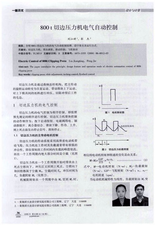
- 格式:doc
- 大小:87.50 KB
- 文档页数:11


125MN油压机的土建及消防设计郝立文【摘要】介绍了太原重工125 MN油压机的土建结构及消防设计.【期刊名称】《中国重型装备》【年(卷),期】2011(000)002【总页数】2页(P44-45)【关键词】油压机;土建;消防【作者】郝立文【作者单位】中国中元国际工程公司,北京100089【正文语种】中文【中图分类】TG315.4+6中元国际工程公司承担了太原重工大型铸锻件国产化研制项目锻造热处理车间的工程设计任务,其中主要设备包括了一台125 MN 油压机。
文章主要介绍油压机的土建和消防设计。
1 油压机的土建结构125 MN 油压机的结构为双柱斜置式,配有钢锭升降台和砧座横移装置,其辅助设备为一台400 t·m 操作机。
在中小吨位压机中,双柱斜置式快锻机在锻造轴类件产品时有着很大的优势。
但是在100 MN 及以上自由锻压机中采用双柱斜置的结构型式,其锻造翻钢机中心线和压机中心线要比四柱压机远,在实际操作时有很多不便。
三梁四柱式压机和双柱压机主要是对工艺有影响,对于土建来说是一样的。
双柱压机在结构上要比三梁四柱压机简单,重量也轻。
在设计土建基础时混凝土基础总重量约为设备重量的1.2 倍。
对土建而言,同等级的压机双柱式压机混凝土基础重量总体来说要比四柱的轻。
125 MN 油压机基础分为两大部分:主机和操作机。
主机基础主要承受竖向荷载。
太重技术中心提供的资料显示:油压机每根柱子下的基础承受的荷载为静荷载18 000 kN,动荷载36 000 kN,总荷载是静荷载和动荷载叠加为54 000 kN。
这样压机主机基础要承受100 MN 以上的压力。
我公司对此观点持保留态度,因为主机基础主要承受压机本体的重量,再加上活动横梁上下移动时对基础的一个冲击力。
技术中心基于安全因素提出的荷载远远大于其真实的荷载,对基础设计而言造成了浪费。
为此,我公司在和太原重工沟通的基础上对其荷载做了部分修改,例如其横向推砧装置区域荷载原设计为静荷载2 000 kN,动荷载3 000 kN,总荷载为5 000 kN。

800M N大型模锻液压机极限设计制造技术创新曾祥东,杨固川,张华,于江,胡孟君,陈文( 中国第二重型机械集团公司重型机械设计研究院,四川成都610052)摘要: 简述800 M N大型模锻液压机上巨大尺寸、重要零件的极限设计制造,特别是机架C形板、主工作缸、活动横梁中梁等的极限设计技术以及在铸造、锻造、焊接方面的极限制造技术。
设计过程中对C形板进行优化设计,使过渡圆角处的最大应力由原来的456M Pa降为237.1M Pa; 对主工作缸的局部进行设计优化,使进液孔内壁的最大主应力和等效应力分别降低到192和217M Pa,应力值降低幅度超过40%。
经过国家科技重大专项课题组联合技术攻关,成功解决了大尺寸重要零件极限设计制造关键技术的难题。
关键词: 模锻液压机; 极限设计; 极限制造D O I: 10.13330/j.iss n.1000-3940.2014.02.019中图分类号: TH163文献标识码: A文章编号: 1000-3940( 2014) 02-0096-06C r e a t io n of li m i t d esig n and manu f a c t u r i n g t ec hn i qu e fo rclose-d ie fo r gi n g h y d r au lic p r ess of 800 M NZ en g Xian g d o n g,Yan g Guchuan,Z han g Hua,Yu Jian g,Hu M en g jun,C hen Wen ( T he Hea vy M achiner y Desi g n andResearch Institute,China Nati o nal Er z h o n g Gr o up C o〃,Chen g du610052,China )A b s t r a c t: T he limit desi g n and manu f acturin g technique of imp o rtant parts w ith lar g e si z es in the800 M N cl o se-die fo r g in g h y draulic press w as described brie f l y,especiall y the limit desi g n techn o l ogy of the“C”shaped plate in f rame,the main c y linder and the c o unter beam of m ov in g cr o sshead,and the limit manu f acture of castin g,fo r g in g and w eldin g〃 T he ma x imum stress at the f illet radius of“C”shaped plate w as reduced f r o m456t o 237.1 M Pa thr o u g h the o ptimi z ati o n desi g n〃 T he ma x imum principal stress and the equi v alent stress of liquid in- let h o le in the main wo rkin g c y linder w ere reduced t o 192and217M Pa respecti v el y b y a l o cal o ptimi z ati o n desi g n,and the stresses w ere decreased b y m o re than40%〃 T hr o u g h j o int technical research of the nati o nal science and techn o l ogy maj o r special pr o ject g r o up,the ke y technical pr o blems of limit desi g n and manu f acture ab o ut imp o rtant parts w ith lar g e si z es w ere success f ull y res o l v ed〃K ey wo r d s: cl o se-die fo r g in g press; limit desi g n; limit manu f acture我国自主设计制造的、世界最大的800 M N ( 8 万吨) 大型模锻油压机,是国家科技重大专项课题,压机于2013年4月在中国二重投产。
主材主材主材主材主材主材主材主材主材主材主材主材主材主材主材主材主材主材9945其它工程机械9945其它工程机械9945其它工程机械9945其它工程机械9945其它工程机械其它工程机械99459945其它工程机械9945其它工程机械9945其它工程机械9945其它工程机械9945其它工程机械9945其他工程机械9945其他工程机械9945其他工程机械其他工程机械99459945其它工程机械9944泵类机械9944泵类机械9944泵类机械9944泵类机械9944泵类机械9944泵类机械9944泵类机械9944泵类机械9944泵类机械9944泵类机械9944泵类机械9943动力机械9943动力机械9943动力机械9943动力机械9943动力机械9943动力机械9943加工机械9943动力机械9939电气线路机械9935钻探及地下工程机械9935钻探及地下工程机械9935钻探及地下工程机械9935钻探及地下工程机械钻探及地下工程机械9935钻探及地下工程机械9935钻探及地下工程机械99359933破碎及凿岩机械9933破碎及凿岩机械破碎及凿岩机械99339931环卫机械9931环卫机械9931环卫机械9931环卫机械9931环卫机械9931环卫机械9931环卫机械9931环卫机械9931加工机械9931环卫机械9929无损探伤机械设备无损探伤机械设备99299927冷却及热处理机械设备9927冷却及热处理机械设备9927冷却及热处理机械设备9927冷却及热处理机械设备焊接机械设备9925焊接机械设备99259925焊接机械设备9925焊接机械设备焊接机械设备99259925焊接机械设备9925焊接机械设备焊接机械设备99259923切割及打磨机械设备9923加工机械9923切割及打磨机械设备9923切割及打磨机械设备9923切割及打磨机械设备9923切割及打磨机械设备9923加工机械9923切割及打磨机械设备9921木工机械加工机械99199919加工机械加工机械99199919加工机械9919加工机械9919加工机械9919加工机械9919加工机械9919加工机械9919加工机械9919加工机械9919加工机械加工机械99199919加工机械9919加工机械9919加工机械9919加工机械9919加工机械9917钢筋和预应力机械9917钢筋和预应力机械9917钢筋和预应力机械9917钢筋和预应力机械9917钢筋和预应力机械9917钢筋和预应力机械9913压实及路面机械9913压实及路面机械9913压实及路面机械9913压实及路面机械9913压实及路面机械9913压实及路面机械9913压实及路面机械9911机动工业车辆9909起重及垂直运输机械9909起重及垂直运输机械9909起重及垂直运输机械9909起重及垂直运输机械9909起重及垂直运输机械9909起重及垂直运输机械9909起重及垂直运输机械9909起重及垂直运输机械9909起重及垂直运输机械9909起重及垂直运输机械9909起重及垂直运输机械9909起重及垂直运输机械9909起重及垂直运输机械9909起重及垂直运输机械9909起重及垂直运输机械9909起重及垂直运输机械9909起重及垂直运输机械9909起重及垂直运输机械9907铲土及水平运输机械9907铲土及水平运输机械9907铲土及水平运输机械9907铲土及水平运输机械9907铲土及水平运输机械9907铲土及水平运输机械9907铲土及水平运输机械9907铲土及水平运输机械9907铲土及水平运输机械9907铲土及水平运输机械9907铲土及水平运输机械9907铲土及水平运输机械9907铲土及水平运输机械9907铲土及水平运输机械9907铲土及水平运输机械混凝土及灰浆用机械9905混凝土及灰浆用机械9905混凝土及灰浆用机械99059905混凝土及灰浆用机械混凝土及灰浆用机械99059905混凝土及灰浆用机械9903桩工、钻孔机械桩工、钻孔机械9903桩工、钻孔机械99039903桩工、钻孔机械9903桩工、钻孔机械9903桩工、钻孔机械9903桩工、钻孔机械桩工、钻孔机械99039903桩工、钻孔机械9903桩工、钻孔机械9903桩工、钻孔机械9903桩工、钻孔机械9903桩工、钻孔机械9903桩工、钻孔机械9903桩工、钻孔机械9903桩工、钻孔机械9903桩工、钻孔机械9903桩工、钻孔机械9903桩工、钻孔机械9903桩工、钻孔机械9903桩工、钻孔机械9903桩工、钻孔机械9903桩工、钻孔机械挖掘机械99019901挖掘机械8027特种混凝土沥青混凝土8025沥青混凝土80258021水泥混凝土8021水泥混凝土8021水泥混凝土8021水泥混凝土水泥混凝土8021水泥混凝土80218021水泥混凝土水泥混凝土80218015胶泥、脂、油8015胶泥、脂、油8015胶泥、脂、油8015胶泥、脂、油8015胶泥、脂、油8011灰浆、水泥浆8009其它砂浆8009其他砂浆8007特种砂浆8001水泥砂浆8001水泥砂浆8001水泥砂浆8001水泥砂浆5547发电机5547发电机3321交通(安全)标志3321交通(安全)标志3321交通(安全)标志3321交通(安全)标志3321交通(安全)标志3321交通(安全)标志3321交通(安全)标志3321交通(安全)标志3321交通(安全)标志3311防撞装置3307路面天然石构件3307路面天然石构件3307路面天然石构件3307路面天然石构件3305路面砖、广场砖3305路面砖、广场砖3305路面砖、广场砖3305路面砖、广场砖3305路面砖、广场砖3305路面砖、广场砖3305路面砖、广场砖3305路面砖、广场砖3305路面砖、广场砖3305路面砖、广场砖3305路面砖、广场砖3305路面砖、广场砖3305路面砖、广场砖3305路面砖、广场砖3305路面砖、广场砖3305路面砖、广场砖3305路面砖、广场砖3305路面砖、广场砖3305路面砖、广场砖3303土工格栅3303土工格栅道路管井、沟、槽等构件3301道路管井、沟、槽等构件3301道路管井、沟、槽等构件3301道路管井、沟、槽等构件33013301道路管井、沟、槽等构件3301道路管井、沟、槽等构件3301道路管井、沟、槽等构件3301道路管井、沟、槽等构件3301道路管井、沟、槽等构件3301道路管井、沟、槽等构件3301道路管井、沟、槽等构件3301道路管井、沟、槽等构件3301道路管井、沟、槽等构件3301道路管井、沟、槽等构件3217电动工具3217电动工具3217电动工具3215气动工具3211手动工具其余周转材料32093209其余周转材料3207胎具、模具类周转材料3207胎具、模具类周转材料3207胎具、模具类周转材料3203脚手架及其配件3203脚手架及其配件3201模板3041其它成型制品3041其他成型制品预制烟囱、烟道30393035装置设备附件3035装置设备附件3035装置设备附件3035装置设备附件3035装置设备附件3035装置设备附件3035装置设备附件3035装置设备附件3035装置设备附件3033机械设备安装用加工件3033机械设备安装用加工件3033机械设备安装用加工件3033机械设备安装用加工件3033机械设备安装用加工件机械设备安装用加工件30333033机械设备安装用加工件3033机械设备安装用加工件3033机械设备安装用加工件3033机械设备安装用加工件3033机械设备安装用加工件3033机械设备安装用加工件3033机械设备安装用加工件3033机械设备安装用加工件3033机械设备安装用加工件3033机械设备安装用加工件3033机械设备安装用加工件机械设备安装用加工件30333033机械设备安装用加工件3033机械设备安装用加工件3033机械设备安装用加工件3033机械设备安装用加工件3033机械设备安装用加工件3033机械设备安装用加工件3033机械设备安装用加工件3033机械设备安装用加工件变形缝3021变形缝3021压力容器构件3007压力容器构件3007压力容器构件30073005铸铁及铁构件3005铸铁及铁构件3005铸铁及铁构件3005铸铁及铁构件3001钢结构制作件钢结构制作件3001钢结构制作件30013001钢结构制作件3001钢结构制作件3001钢结构制作件钢结构制作件3001钢结构制作件3001钢结构制作件30013001钢结构制作件3001钢结构制作件3001钢结构制作件3001钢结构制作件3001钢结构制作件3001钢结构制作件3001钢结构制作件3001钢结构制作件3001钢结构制作件3001钢结构制作件3001钢结构制作件3001钢结构制作件3001钢结构制作件3001钢结构制作件3001钢结构制作件3001钢结构制作件3001钢结构制作件钢结构制作件3001钢结构制作件30013001钢结构制作件3001钢结构制作件3001钢结构制作件3001钢结构制作件3001钢结构制作件3001钢结构制作件3001钢结构制作件3001钢结构制作件3001钢结构制作件3001钢结构制作件3001钢结构制作件3001钢结构制作件3001钢结构制作件3001钢结构制作件3001钢结构制作件3001钢结构制作件3001钢结构制作件3001钢结构制作件3001钢结构制作件3001钢结构制作件3001钢结构制作件3001钢结构制作件3001钢结构制作件3001钢结构制作件3001钢结构制作件3001钢结构制作件3001钢结构制作件3001钢结构制作件3001钢结构制作件钢结构制作件30013001钢结构制作件钢结构制作件3001钢结构制作件30013001钢结构制作件3001钢结构制作件3001钢结构制作件钢结构制作件30013001钢结构制作件3001钢结构制作件3001钢结构制作件3001钢结构制作件3001钢结构制作件3001钢结构制作件3001钢结构制作件3001钢结构制作件3001钢结构制作件3001钢结构制作件3001钢结构制作件钢结构制作件3001钢结构制作件30013001钢结构制作件钢结构制作件3001钢结构制作件30013001钢结构制作件钢结构制作件3001钢结构制作件30012935其它园林绿化器材2935其它园林绿化器材2935其它园林绿化器材2935其它园林绿化器材2935其它园林绿化器材2935其它园林绿化器材2929园艺资材2929园艺资材2929园艺资材2923假山、观景石2923假山、观景石2923假山、观景石2907地被植物2907地被植物2907地被植物其余仿古材料2823其余仿古材料2823其余仿古材料28232823其余仿古材料其余仿古材料2823其余仿古材料28232823其余仿古材料2823其余仿古材料2823其余仿古材料2823其余仿古材料2823其余仿古材料2811粘土瓦件(黑活瓦件)2811粘土瓦件(黑活瓦件)粘土瓦件(黑活瓦件)2811粘土瓦件(黑活瓦件)2811粘土瓦件(黑活瓦件)2811粘土瓦件(黑活瓦件)2811粘土瓦件(黑活瓦件)2811粘土瓦件(黑活瓦件)2811粘土瓦件(黑活瓦件)2811粘土瓦件(黑活瓦件)2811粘土瓦件(黑活瓦件)2811粘土瓦件(黑活瓦件)2811粘土瓦件(黑活瓦件)2811粘土瓦件(黑活瓦件)2811粘土瓦件(黑活瓦件)2811粘土瓦件(黑活瓦件)28112811粘土瓦件(黑活瓦件)2811粘土瓦件(黑活瓦件)2811粘土瓦件(黑活瓦件)2811粘土瓦件(黑活瓦件)2811粘土瓦件(黑活瓦件)2811粘土瓦件(黑活瓦件)粘土瓦件(黑活瓦件)28112811粘土瓦件(黑活瓦件)2811粘土瓦件(黑活瓦件)粘土瓦件(黑活瓦件)28112811粘土瓦件(黑活瓦件)2811粘土瓦件(黑活瓦件)2811粘土瓦件(黑活瓦件)2811粘土瓦件(黑活瓦件)2811粘土瓦件(黑活瓦件)2811粘土瓦件(黑活瓦件)2811粘土瓦件(黑活瓦件)2811粘土瓦件(黑活瓦件)2811粘土瓦件(黑活瓦件)2811粘土瓦件(黑活瓦件)2811粘土瓦件(黑活瓦件)2811粘土瓦件(黑活瓦件)2811粘土瓦件(黑活瓦件)2811粘土瓦件(黑活瓦件)2811粘土瓦件(黑活瓦件)2811粘土瓦件(黑活瓦件)2811粘土瓦件(黑活瓦件)2811粘土瓦件(黑活瓦件)2811粘土瓦件(黑活瓦件)2811粘土瓦件(黑活瓦件)2811粘土瓦件(黑活瓦件)2811粘土瓦件(黑活瓦件)2811粘土瓦件(黑活瓦件)2811粘土瓦件(黑活瓦件)2811粘土瓦件(黑活瓦件)2811粘土瓦件(黑活瓦件)2811粘土瓦件(黑活瓦件)2811粘土瓦件(黑活瓦件)2811粘土瓦件(黑活瓦件)2811粘土瓦件(黑活瓦件)2811粘土瓦件(黑活瓦件)2811粘土瓦件(黑活瓦件)2811粘土瓦件(黑活瓦件)2811粘土瓦件(黑活瓦件)2811粘土瓦件(黑活瓦件)2811粘土瓦件(黑活瓦件)2811粘土瓦件(黑活瓦件)2811粘土瓦件(黑活瓦件)2811粘土瓦件(黑活瓦件)2811粘土瓦件(黑活瓦件)2811粘土瓦件(黑活瓦件)2811粘土瓦件(黑活瓦件)2811粘土瓦件(黑活瓦件)2811粘土瓦件(黑活瓦件)2811粘土瓦件(黑活瓦件)2811粘土瓦件(黑活瓦件)2811粘土瓦件(黑活瓦件)2811粘土瓦件(黑活瓦件)2811粘土瓦件(黑活瓦件)2811粘土瓦件(黑活瓦件)2811粘土瓦件(黑活瓦件)2811粘土瓦件(黑活瓦件)粘土瓦件(黑活瓦件)2811粘土瓦件(黑活瓦件)2811粘土瓦件(黑活瓦件)2811粘土瓦件(黑活瓦件)2811粘土瓦件(黑活瓦件)2811粘土瓦件(黑活瓦件)2811粘土瓦件(黑活瓦件)2811粘土瓦件(黑活瓦件)2811粘土瓦件(黑活瓦件)2811粘土瓦件(黑活瓦件)28112811粘土瓦件(黑活瓦件)2811粘土瓦件(黑活瓦件)2811粘土瓦件(黑活瓦件)2811粘土瓦件(黑活瓦件)2811粘土瓦件(黑活瓦件)2811粘土瓦件(黑活瓦件)2811粘土瓦件(黑活瓦件)2811粘土瓦件(黑活瓦件)2811粘土瓦件(黑活瓦件)2811粘土瓦件(黑活瓦件)2811粘土瓦件(黑活瓦件)2811粘土瓦件(黑活瓦件)2811粘土瓦件(黑活瓦件)2811粘土瓦件(黑活瓦件)2811粘土瓦件(黑活瓦件)2811粘土瓦件(黑活瓦件)2811粘土瓦件(黑活瓦件)2811粘土瓦件(黑活瓦件)2811粘土瓦件(黑活瓦件)2811粘土瓦件(黑活瓦件)2811粘土瓦件(黑活瓦件)2811粘土瓦件(黑活瓦件)2811粘土瓦件(黑活瓦件)2811粘土瓦件(黑活瓦件)2811粘土瓦件(黑活瓦件)2811粘土瓦件(黑活瓦件)2811粘土瓦件(黑活瓦件)2811粘土瓦件(黑活瓦件)2811粘土瓦件(黑活瓦件)2811粘土瓦件(黑活瓦件)2811粘土瓦件(黑活瓦件)2811粘土瓦件(黑活瓦件)2811粘土瓦件(黑活瓦件)2811粘土瓦件(黑活瓦件)2811粘土瓦件(黑活瓦件)2811粘土瓦件(黑活瓦件)2811粘土瓦件(黑活瓦件)2811粘土瓦件(黑活瓦件)2811粘土瓦件(黑活瓦件)2811粘土瓦件(黑活瓦件)2811粘土瓦件(黑活瓦件)2811粘土瓦件(黑活瓦件)2811粘土瓦件(黑活瓦件)2811粘土瓦件(黑活瓦件)2811粘土瓦件(黑活瓦件)2811粘土瓦件(黑活瓦件)2811粘土瓦件(黑活瓦件)。
摘要本次设计题目是800T液压机设计,四柱式液压机式液压机中最常见,应用最广的一种结构形式。
其主要特点是加工工艺性较其他类型液压机简单。
所以设计成立式单缸四柱式液压机结构。
它的机身是由上横梁,活动横梁,工作台,四根立柱组成。
工作缸安装在上横梁,活动横梁和工作缸成一个整体,以立柱为导向上下运动,并传递工作缸产生的力量,对制件进行压力加工。
由于机身连接成一个整体框架,故机身承受整个工作力量。
四柱式液压机主要不足之处:〔1由于用四根立柱做框架,机身刚度较框架式小。
〔2由于四立柱做向导,活动横梁导套与四根立柱磨损后不易调整。
四柱式液压机组成部分可分为:工作部分:工作油缸,活动横梁等。
机身部分:由上横梁,工作台及立柱组成。
辅助部分:包括顶出缸,移动工作台等。
设计过程中包括液压机的结构设计,液压系统方案设计及工作原理图的拟定,还有油量,油箱的计算,其中前三个环节最为重要。
国液压机的主要设计单位,包括占主导地位的第一重型机械集团公司在的一些大型所,其设计工作仍然是以图版作业为主,设计工作的好与坏完全取决于设计人员的技术与素质。
关键词:油缸:液压系统:工作台:活塞杆:顶出缸AbstractThis design topic is 800t hydraulic press design, four column hydraulic machine hydraulic machine is the most common, the most widely used a structure. Its main feature is that the process of machining is simpler than other hydraulic pressure.. So the establishment of design type single cylinder four column hydraulic machine structure. Its fuselage is composed of beams, movable beams, working table, four pillars. Cylinder installed in the beam, the movable beam and a working cylinder link into a whole, in the column for the directed motion, and transmit power generated in the working cylinder, pressure processing of parts. As the fuselage connected into a whole frame, so the fuselage to withstand the entire working force.Four column hydraulic press main deficiencies:First, for the four pillars of the framework, the fuselage frame stiffness is relatively small.Second, due to the four column to do the guide, the movable beam inside guide set and four column wear not easy to adjust.Four column hydraulic machine parts can be divided into:Working part: working cylinder, movable beam, etc..Body part: from the upper beam, working table and column.Auxiliary parts: including the ejector cylinder, mobile workbench, etc.. Design process including the structure of the hydraulic machine design,hydraulic system design and work principle diagram, as well as the amount of oil, fuel tank, which is the first three most important.The main units of domestic hydraulic machine design, including dominated the first heavy machinery group company and Design Institute, including some large Design Institute, the design work is still dominated by plate work, design work is good or bad depends entirely on the design personnel of technology and quality.Keywords:Cylinder: hydraulic system: bench: piston rod: ejector cylinder目录引言..................................... 错误!未定义书签。
静压机制砖机是一种现代化的砖机设备,在建筑行业和土木工程中得到了广泛应用。
其能够在不同的工作环境下高效地生产制砖,具有稳定的性能和可靠的质量。
其中,800吨静压机制砖机作为其中一种型号,在技术参数方面有着独特的优势和特点。
下面将对800吨静压机制砖机的技术参数进行详细介绍。
一、外观和结构1. 外观:800吨静压机制砖机外观整体采用钢结构设计,外形美观,底部带有脚轮,便于移动和安装。
2. 结构:整机采用模块化设计,便于拆装和维护,具有较强的结构稳定性。
二、工作性能1. 压力:800吨静压机制砖机的压力参数为800吨,能够满足不同规格的砖坯压制需求。
2. 工作速度:具有快速下压和回程速度,提高了生产效率,每分钟可压制多块砖坯。
3. 自动化程度:配备自动控制系统,能够实现自动化生产,节约人力资源,减少人为错误。
三、电气部分1. 电机功率:800吨静压机制砖机配备大功率电机,保证了设备的高效稳定运行。
2. 控制系统:采用先进的PLC控制系统,具有良好的稳定性和可靠性,可实现各种工艺参数的自动设定和调整。
四、液压系统1. 油泵:选用高品质的液压油泵,工作稳定,抗压能力强。
2. 阀门:采用进口液压阀,具有灵敏的调节性能和良好的密封性。
五、附属设备1. 模具:配套多种规格的模具,可根据需要进行更换,适用于不同类型的砖坯生产。
2. 输料系统:具备自动进料系统,可实现连续、稳定地供料,提高了生产效率。
800吨静压机制砖机在技术参数上表现出众,具有较高的工作效率和稳定性能,能够满足不同工程项目的砖坯生产需求。
其广泛的应用领域和可靠的质量表现,使其成为建筑行业和土木工程中不可或缺的重要设备之一。
为了更全面地了解800吨静压机制砖机的技术参数和性能,接下来将对其工作原理、维护保养、安全操作等方面进行详细介绍,并探讨其在建筑行业和土木工程中的应用前景。
六、工作原理1. 压制过程:当砖机启动后,液压系统通过油泵将液压油压送到液压缸中,从而驱动活塞向下移动,施加压力将原料压制成砖坯。
Models 6-225, 6-425, 6-250, 6-450,6-275, 6-475, 6-650, and 6-850Air Hydraulic PressesWARNING LABELSTo the left is the safety Alert symbol. When you see these safety alert symbols on your press, Array be alert to the potential for personal injury.Follow recommended precautions and safe operating practices.SETTING UP THE PRESS FOR OPERATIONFor shipping convenience, some of the parts are not assembled. Assemble these parts in the following order:1. Bolt the base angles to uprights using four bolts and nuts, which are provided. Make sure baseangles are against stops on uprights.NOTE: The press should set on a level floor with the base angles touching the floor at allpoints. Use shims where necessary.2. Connect airline into street elbow (Item No. 136) at right hand side of control block.NOTE: Avoid restrictions in air supply line to insure ample air-to-air motor. To ensuremaximum performance the air supply line should be ½” pipe line if the distance from thecompressor to press is 0-30 feet, ¾” line 30-60 feet, and 1” if greater than 60 feet.NOTE: AIR MUST BE MOISTURE FREE. WATER IN AIR LINE WILL CORRODE THIS PRESSBEYOND REPAIR.3. Oil Requirements: Fill reservoir with Mobil DTE 24 or equivalent oil thru pipeline in back of press atpipe coupling by removing pipe plug. NOTE: Make sure the air-source is removed from thereservoir prior to removal of plug. Oil level may be checked (with ram up) by removing thepipe plug on the right side of reservoir near the front. Replace plug before operating the press.Model 6-225 & 6-425 25-ton presses use 6 quartsModel 6-250 & 6-450 50-ton presses use 8 quartsModel 6-275 & 6-475 75-ton presses use 10 quartsModel 6-650 & 6-850 150-ton presses use 20 quarts.4. Attach nose piece to ram by inserting shank into ram and tightening the set screw.5. CAUTION! Place the hoist crank on the lift drum shaft. Turn the hoist crank to relievethe pressure on the table pins. Keeping tension on the hoist crank, remove the table pins one at a time. After removing the tables pins, turn the crank running the table channels from top to bottom. Check to make sure the cable is tracking correctly. The cable should be on each ofthe two upper pulleys and should track back and forth on the cable drum. Always place tablepins under the table channels before releasing the hoist crank when positioning the tablechannels for cable tracking, servicing, or set-up for desired work opening. If a trackingproblem exists, contact the Dake factory for instructions. Be sure all table pins are fullyinserted in place before applying pressure. Always remove or release pressure on the cablebefore pressure is applied.Optional EquipmentRemote relief valve- part number 713510.OPERATIONSWARNING: DO NOT OVERSTROKE THE RAM. Overstroking will cause premature seal failure. Models 6-225, 6-425, 6-250, 6-275 and 6-475 have a 10-inch stroke. Models 6-650 and 6-850 have a 16-inch stroke.The press has been completely tested at the factory and after setting up according to instructions above, the press is ready for operation. However, it is necessary for the operator to acquaint themselves with the controls.1. Three screws (item 109) are used to lock the workhead in the desired position along headchannels.2. The handcrank (item 19) is provided to raise or lower the table channels to the proper work height.When desired height is obtained insert the table pins. Models 6-225, 6-425, 6-250 and 6-450 use 2pins on each side (4 total) and Models 6-275, 6-475, 6-650 and 6-850 use 3 pins on each side (6total). NOTE: Be sure ALL table pins are in place an in as far as they can go before pressureis applied. Be sure to slack off on the cable before pressure is applied. (Refer to point 5under SETTING UPS THE PRESS FOR OPERATION)3. The handle on the left side of the control block (item 76) opens and closes the ball valve, whichreleases pressure on the ram. This valve should be kept firmly closed and opened only when it isdesired to return the ram to its up position.4. The two table plates and two V-blocks are used for supporting the work in process.5. The control knob (item 103) on the right side of the panel regulates the speed of ram travel. Theknob will return to the off position when released.6. The relief valve (item 90) has been set at factory to open at maximum tonnage of press. The valvecan be adjusted by removing hex nut located on top of the valve block at the right front of reservoirand turning the adjusting screw to the left for a lower setting. WARNING: Never exceed ratedtonnage of press.MAINTENANCECAUTION: When disconnecting any parts of this machine be extremely careful that all parts are clean to prevent entrance of dirt in the hydraulic system.1. If press loses Pressure:a. Check all tubing joints for leaks and tighten the tube nuts.b. Leakage past release valve (Item 72). Drain the reservoir, and remove packing nut (Item75),valve rod (Item 73), and ball valve (Item 72). Clean out valve seat and reseat ball valve usingbrass rod as a drift striking sharply with a hammer. Reassemble valve rod, packing and packingnut. Refill reservoir with appropriate oil amount.c. Leakage past eductor inlet check ball (Item 69). Drain reservoir, remove large pipe plug (Item71), valve seat (Item 70), and check ball (Item 69). Clean and inspect seat. Reseat ball on seator replace seat with a new one if necessary. Reassemble with ball above the seat tighteningplugs securely.d. Worn cup leather (Serial No < 192522) or T-ring seal (Serial No > 192523). If none of theprevious conditions seem to have been the cause of the trouble, the cup leather or T-ring sealmay be worn out or damaged. To inspect this it is necessary to drain the oil and remove theworkhead from the press frame. Remove tube assembly (Item 144). Set 2 4x4 blocks on thetable then raise table channels with the block up to the bottom of the reservoir applying pressureto the reservoir. Remove roller brackets from the reservoir and lower workhead using the table.WARNING: Be sure that stroke indicator rod support (item 61) is installed in the side ofthe piston. If not, Insert ½”-13 stud or capscrew in tapped hole in piston. This will holdcylinder off piston. The piston leather or T-ring seal can now be inspected and replaced ifnecessary. Press may be reassembled in reverse order being careful not to damage the lip ofthe leather cup or T-ring seal as it enters the cylinder.2. If press will not develop rated tonnage.a. Dirt under valve balls. Refer to MAINTENANCE 1 – c above.b. Worn cup leather. Refer to MAINTENANCE 1 – d above.c. Relief valve not set properly. This valve is located on the top side near the right end of thecontrol block at the front of the reservoir. The valve is set at the factory to bypass oil from thepump back to the reservoir when the press reaches its rated capacity. The load on the spring(Item 91), which governs the pressure at which the valve will bypass oil, is adjusted by turningthe screw (Item 90) in to increase pressure or out to decrease pressure. Replace seal (Item89) and cap nut (Item 88). NOTE: We advise that the relief valve not be tampered withafter it is once set at the capacity of the press.3. If nothing happens when press is operated.a. Release valve open. Be sure to have release valve firmly closed when using press.b. If the ram will come down only a fraction of its rated stroke, check the oil level in the reservoirwith the ram at the top of its stroke. It should be visible in the sight window at the side of thereservoir.4. If press is operating slow.a. Check air supply line for restrictions to determine if air motors are getting ample supply of air.b. Release valve not closed properly. Release valve must be firmly closed when using the press.c. Wrong hydraulic fluid. After considerable research and tests made with the cooperation of thepump manufacturer, we recommend Mobil DTE 24 oil or equivalent.5. If Oil is coming out of the air vent.Drain out the spring chamber by removing the 1/8” pipe plug, which is put in the hub or boss that contains the oil seal where the ram extends out of the reservoir. Once oil is drained, run the press up to full tonnage with pipe plug still out. Excessive oil is a sign that the head seal has been damaged.Refer to Maintenance section 1 item d to replace seal. Replace pipe plug.6. Excessive leakage around the ram.Drain out the spring chamber as instructed in Maintenance section 5. A small amount of oil in this chamber facilitates lubricating the bushing the ram passes thru and prevents scoring. However, if operation performed on press is spoiled due to slight leakage of oil, remove pipe plug as described in MAINTENANCE 5 and connect tube line to continually drain this chamber.WARNING LABELSTo the left is the safety Alert symbol. When you see these safety alert symbols on your press, be alert to the potential for personal injury.Follow recommended precautions and safe operating practices.Carefully read all safety messages in these instructions and on your press safety signs.Keep safety labels in good condition. Replace missing or damaged safety labels. This machine is intended to be operated by one person. This person should be conscious of the press ram movement not only forLabel 300168 Label 84487Label 84399Label Placement ViewLabel 84395 Label 76462Label 7355Control Block Exploded ViewGrand Haven, MI 49417Phone: 616-842-7110 800-937-3253Fax: 616-842-0859 800-846-3253Web: E-mail: *********************************************************Ite m Part NameModel6-2256-425Model6-2506-450Model6-2756-475Model6-6506-850Qty1 Pulley 602-25H 602 727 1563 22 Frame 700134 700116 706943 701030 13 Hex head cap screw 43341 43342 43361 43720 24 Name plate 81002 81002 81002 81003 15 6-32 x ½” Self tapping screw 43876 43876 43876 43876 46 Table plate 966 545 702 1534 27 V-block - 336 336 1576 28 Table spacer assembly 716691 716692 716788 1553 49 Table channel 701020 701091 706945 701032 210 Lockwasher 43647 43647 43648 43649 811 Hex nut 43916 43916 43917 43919 812 Table pins 981 569 - - 4Table pins - - 569 7205 6 Safety clips 302816 613 Base angle 978 566 566 1551 214 Hex cap screw 43349 43349 43349 43365 415 Lockwasher 43647 43647 43647 43648 416 Square nut 43916 43916 43916 43917 417 Cable 988 580 726 1562 118 Cable clamp 991 991 991 583 419 Hoist crank assembly 701653 701653 701653 701653 120 Worm shaft 7530 7530 7530 742 1 21A Retaining ring 43978 43978 43978 43982 2 21B Retaining ring 27437 27437 27437 43983 222 Worm key 386 386 386 746 123 Worm 385 385 385 744 124 Hoist frame 725 725 725 739 125 Hex cap screw 43335 43335 43335 43353 226 Hex nut 43912 43912 43912 43916 227 Drum shaft 724 724 724 741 128 Drum key 737 737 737 745 129 Worm gear 736 736 736 743 130 Cable drum 723 723 723 740 1 Complete Table Hoist Assembly(Items 20, 21A, 21B, 22, 23, 24, 27, 28, 29,30)701677-S 701677-S 701677-S 700111-S 1Figure 237 ½” Hex Nut 43916 43916 43916 43916 6 39 Cylinder Gasket 9776 9777 9777 9778 140 ½”-13 x 1-½” Soc. Hd. Cap Screw(Serial No. < 192522) -- 43471 43471 -- 141 Piston Bumper (Serial No. < 192522)-- 2221 2221 -- 142 ¼”-20x1” HHCS (Serial No. < 192522)43305 -- -- -- 43/8”-16x1-¼” HHCS (Serial No. < 192522)-- 43330 -- -- 6 3/8”-16x1-¾” HHCS (Serial No. < 192522)-- -- 43332 43332 8 43 ¼” Lockwasher (Serial No. < 192522)43643 -- -- -- 43/8” Lockwasher (Serial No. < 192522)-- 43645 43645 43645 6-844 Supporting Ring (Serial No. < 192522)967 4110 2222 1536 145 Leather Cup (Serial No. < 192522)969 557 706 1538 1T-ring Seal (Serial No. > 192523)17976 17878 17942 37052 146 Cylinder 7361 4101 2213 4197 147 Piston Assembly (Serial No. < 192522)701401 701402 701403 701404 1Piston Assembly (Serial No. > 192523)716225 716226 716227 716228 1 48 Ram Spring (Small) 5722 4107 2231 4196 1Figure 150 Ram Spring (Large) 5721 4106 2232 4195 1Ite m Part NameModel6-2256-425Model6-2506-450Model6-2756-475Model6-6506-850Qty51 Piston Bushing (Serial No. < 192522)5731 4111 2229 1158 1Wear Ring (Serial No. > 192522)76805 76806 76807 3704552 Oil Seal 6019 6020 6021 1477 153 Oil Seal Gasket 6516 6517 6518 6519 154 Retaining Plate 7359 6513 6514 6474 155 No. 10-24 x ½“ Rd. Hd. Screw 43881 43881 43881 43881 4-656 5/16” Set Screw 43575 43575 43575 43575 157 Nose Piece Assembly 701706 701707 701708 701709 158 V-Nose Assembly 701710 701711 701712 701713 159 Stroke Indicator Rod 2260 2260 2260 4264 160 ½“-13 Hex Jam Nut 43940 43940 43940 43940 161 Special Nut 2259 2259 2259 2259 162 ¼“-20 x ¼” Soc. Hd. Set Screw 43558 43558 43558 43558 163 Support Stud 2258 2258 2258 4266 164 No. 2 x 3/16” Drive Screw 43616 43616 43616 43616 365 Scale 2261 2261 2261 4265 166 Reservoir Assembly 715266 716784 716784 715269 167 1/8” N.P.T.F. Soc. Hd. Pipe Plug 589 589 589 589 268 Check Valve Seat 1300 1300 1300 1300 269 ½” N.P.T.F. Soc Hd. Pipe Plug 596 596 596 596 370 3/8” N.P.T.F. Soc Hd. Pipe Plug 588 588 588 588 571 ¼” N.P.T.F. Soc. Hd. Pipe Plug 1567 1567 1567 1567 172 Ball Valve ¾“ Dia. 1936 1936 1936 1936 173 Release Valve Rod 2257 2257 2257 2257 174 Valve Rod Packing 1937 1937 1937 1937 775 Packing Nut 1931 1931 1931 1931 176 Valve Handle 2230A 2230A 2230A 2230A 177 Handle Washer 348 348 348 348 178 3/8”-16 x ¾“ Hex Cap Screw 43326 43326 43326 43326 179 Plunger Unit 6151 6151 6151 6151 180 Pivot Pin 6152 6152 6152 6152 181 Air Control Arm 6153 6153 6153 6153 182 Air Control Link 6154 6154 6154 6154 185 Air Control Shaft 6156 6156 6156 6156 186 Pin 5772 5772 5772 5772 387 1/16” x ½” Cotter Pin 44049 44049 44049 44049 688 Valve Cap Nut 2236 2236 2236 2236 189 O-ring 3965 3965 3965 3965 190 Relief Valve Adj, Screw 2237 2237 2237 2237 191 Relief Valve Spring 893 893 893 893 192 Ball Retainer 892 892 892 892 193 Ball Valve ¼” Dia. 918 918 918 918 194 Relief Valve Seat 891 891 891 891 195 Check Valve Spring 579 579 579 579 196 Check Valve Spring 890 890 890 890 197 Ball Valve ½” Dia. 586 586 586 586 2 100 No. 10-24 x 2-¾” Machine Screw 300248 300248 300248 300248 4 101 Gauge 71270 71271 71272 71273 1103 Control Knob 2250A 2250A 2250A 2250A 1Ite m Part NameModel6-2256-425Model6-2506-450Model6-2756-475Model6-6506-850Qty104 ¼”-20 x ½” Soc. Hd. Set Screw 43562 43562 43562 43562 1 105 ½” Washer 43634 43634 43634 43634 1 106 5/8”-11 Hex Nut 43917 43917 43917 43917 7 108 Rear Roller Bracket 9472 9472 9472 4204 1 109 ¾”-10 x 3” Set Screw 43616 43616 43616 43616 3 112 Flanged Roller 2244 2244 2244 2244 3 113 Bearing 6023 6023 6023 6023 3 114 Front Roller Bracket 9473 9473 9473 4205 1 115 Pump – Haskel Air 63453 63453 63453 63453 1 116 3/8” Pipe Nipple 58226 58226 58226 58226 1 123 ¾” x 4” Pipe Nipple 1818 1818 1818 1818 1 124 ¾“ 90° Pipe Elbow 74017 74017 74017 74017 1 125 ¾“ x 2” Pipe Nipple 58227 58227 58227 58227 1 126 ¾“ Pipe Coupling 1744 1744 1744 1744 1 128 3/8” Street Elbow 1264 1264 1264 1264 2 129 3/8” Pipe Nipple 58226 58226 58226 58226 1 130 Quick Exhaust 1911 1911 1911 1911 1 132 Restrictor 7368 7368 7368 7368 1 133 3/8” Pipe Nipple 58226 58226 58226 58226 1 134 ¼“ - 1/8” Bushing 1100 1100 1100 1102 3 136 ¼“ 90° Street Elbow 1110 1110 1110 1110 1 137 ¼“ Pipe Coupling 1330 1330 1330 1330 1 138 Check Valve 1841 1841 1841 1841 1 139 Tube Fitting 19576 19576 19576 19576 5 140 Air Vent 632 632 632 632 1 141 Tube 7680 7681 7682 7683 1 142 Tube 7684 7684 7684 7685 1 143 Tube Elbow 1944 1944 1944 1944 2 144 Tube Assembly 701719 701720 701721 701722 1 145 Tube Elbow 1252 1252 1252 1252 2 146 Tube Assembly 701723 701723 701723 701724 1 147 Tube Elbow 1248 1248 1248 1248 2 148 Tube Assembly 701725 701725 701725 701726 1 Cylinder Repair Kit (Items: 39, 45, 52, 53, 72,74, 89, 93, 97)713053 713054 713055 713056 1 Haskel Pump Repair Kit 713034 713034 713034 713034 1-2 ADDED PARTS USED WITH DOUBLE PUMP PRESSES NOT ILLUSTRATED115 Pump 63453 63453 63453 63453 1 139 Tube Fitting 597 597 597 597 5 149 Tube Tee 1249 1249 1249 1249 1 150 Tube Tee 7693 7693 7693 7693 1 151 Tube Assembly 701727 701727 701727 701728 1 152 Straight Fitting 1251 1251 1251 1251 1 153 Tube Assembly 701729 701729 701729 701729 1 154 Straight Fitting 1247 1247 1247 1247 1 155 Tube Assembly 701730 701730 701730 701731 1Model 6-225, 6-425, 6-250, 6-450,11 6-275, 6-475, 6-650, & 6-850。
技术协议Y98-800液压成型机技术协议协议编号:签约时间:签约地点:宁国Y98-800液压成型机协议编号:甲方: 保隆(安微)汽车配件有限公司乙方:就甲方委托乙方制造Y98-800液压成型机设备/系统(甲方向乙方采购Y98-800液压成型机设备事宜),经双方友好协商达成共识,签订本技术协议,如下:一、总则1.1本协议书使用范围,仅限于Y98-800液压成型机设备/系统订货、安装、调试及售后服务等方面。
1.2本协议书提出的是最低限度的技术要求,并未对一切技术细节作出规定,也未充分引述有关标准和规范的条文,乙方应保证提供符合本协议书和有关最新工业标准的成熟优质产品。
1.3在签定协议之后,甲方保留对本协议书提出补充要求和修改的权力,乙方应允诺予以配合。
如提出修改,具体项目和条件由甲、乙双方商定。
1.4本协议书所使用的标准如与乙方所执行的标准发生矛盾时,按较高标准执行。
1.5本协议书作为采购合同(编号:)的技术附件,与合同正文同时生效。
本协议书所使用的标准以现行国家标准/行业标准/双方约定标准,如不一致时,按较高标准执行。
1.6本协议只在本次设备采购事宜中有效。
二、供货范围及用途:供货产品名称规格型号数量生产厂家液压成型机 Y98-800 1用途:本机为数控成型机,该机主要用途是为管件成型工艺专用设备,适用于车身结构件系列项目。
机器为三梁四柱式结构,主要由主机、充液系统、液压控制系统、电气控制系统等组成。
本机器重约???吨,容许±3%公差。
三、设备/工程组成及工作条件3.1本机主要采用比例阀控制,系统压力、压制速度、油缸行程、保压时间,泄压时间均可在触摸屏上调节,能完成定压成形和定程成形工艺方式,具有压制后保压延时及自动回程动作。
3.2工作条件:3.2.1系统工作区域温度:-10~45℃,湿度:最大95%。
3.2.2供电电压:380V三相四线制,50HZ,电压波动范围:+/-10%。
3.2.3液压系统介质:YB-N46抗磨液压油。
3.2.4水压系统工作介质: MDT乳化剂(5%)+水(95%)。
四、技术要求4.1 主要技术参数:序号项目单位参数备注1 主缸公称力KN 2*4000 二主缸,一快速缸2 液压最大工作压力Mpa 253 最大开口高度mm 15004 滑块最大行程mm 8005 主缸下行速度快下mm/s300 工作7-126 滑块回程速度mm/s 250mm/s7 工作台左右(柱内)2010 mm 前后(柱内螺母内侧)810 mm8 主电动机功率KW 459 压制速度 % 30-100 可调10 压机压力Mpa 5-25 可调11 滑块跟工作台面平行度mm >0.112 工作台到地面高度mm 8004.2 性能特点:4.2.1 机身采用三梁四柱式结构,上梁、工作台通过立柱和紧固螺母、调整螺母结合成一个固定机架,机架精度靠调节螺母调整,乙方保证活动梁、上梁、工作台无变形等情况,如果变形影响精度要更换。
上梁、活动梁、工作台(底座)等大件为钢板焊接件,材料为Q235-B,采用二氧化碳气体保护焊,焊后回火消除应力。
4.2.2 滑块位于机身中间,其上平面与主油缸相连,滑块采用四柱导向方式。
滑块行程控制采用位移传感器控制,确保滑块在行程范围内安全工作。
为保证换模工作的安全,在滑块的最上位置设有上死点电动插销式锁紧机构或者是液压式插销式锁紧机构,滑块锁紧机构操作位置在主操作面板上。
操作方式为手动单独操作,与主机其它动作互锁,滑块锁紧必须保证设备在调模时锁住活动梁不下滑。
滑块下平面设有T型槽,(具体设计好由甲方确认后乙方实施)。
采用电动稠油润滑装置,并配有集油盒,对导柱与导套面进行润滑。
立柱为45#钢,淬火处理,硬度HRC45以上,表面镀硬铬,厚度0.03-0.05mm。
4.2.3 上梁为箱形结构的钢板焊接件,上梁内装有主工作油缸,上面装有安全维修平台和充液油箱,四周采用安全护栏,外形美观。
4.2.4 工作台为钢板焊接结构件,上部为一块厚钢板与四周钢板及筋板焊接后成为具有800T承载能力的构件。
4.2.5 主油缸:液压机主吨位由三缸结构,二主缸加压实现锁模,中间一个快速缸。
油缸通过螺母安装固定在上横梁上。
油缸、活塞杆和柱塞杆采用优质碳素钢锻件。
活塞杆、柱塞杆其表面经中频淬火处理,硬度在HRC45以上,表面镀硬铬,厚度0.03-0.05mm。
活塞油缸内表面经过强滚压工艺。
主油缸密封采用进口密封圈(NOK),快速缸耐压25MPA、三主缸是柱塞缸。
4.2.7 机身整体颜色为9016,安全部分采用国标警示颜色。
4.2.8在主机立柱和主缸上所有螺母、螺栓和边板处各加两个红色三角箭头标识。
4.2.9三梁四柱整机需满足300mm×600mm大模具承受8000KN力所需整机强度。
4.3、液压系统:4.3.1 液压传动系统由能量转换装置(包括油缸、油泵、电机等),能量调节控制装置(包括控制阀集成、先导阀、充液系统、各种压力阀、方向阀等)、辅助装置(包括油箱、冷却系统、循环过滤系统、管路等)及液压附件(如滤油器、管接头、压力表、液位计等),通过电气系统的控制完成各种动作。
4.3.2 液压动力机构安装在机身后方(具体位置由乙方提供),由泵、电机、阀集成块,油箱等组成,动力机构中包括油液过滤,油冷却、油温油位显示等多种装置,主油泵采用轴向柱塞泵。
油泵电机组卧式安装在油箱下部,油箱上部安装有阀集成。
4.3.3 液压系统采用二通插装阀,主缸下腔有二级支承系统,确保在某一元件突然失灵的情况下滑块不会下落。
主缸压力可在5MPa~25MPa间调节,主缸流量可以调节,系统中设有安全阀,以限制液压系统的最高压力,压力比例阀和流量比例阀采用日本油研品牌。
4.3.4 在关键部位设有压力检测点,通过压力检测点可以快速的诊断液压机出现的故障和监测液压机的工作状态。
4.3.5 油液过滤及冷却:油液过滤采用大容量精密滤油器,并带有堵塞报警发讯装置,当滤油器被污物堵塞即可发讯报警,提示维修人员清洗或更换滤芯。
采用强制冷却机进行油液冷却,当油温高于40℃时,自动启动冷却装置,当油温高于55℃时发讯报警,显示报警信号,当油温达到60℃时,控制系统切断电源,强制停机,此时除润滑泵和低压泵外,其余油泵都停止工作,保证系统在允许的温度范围内工作。
4.3.6 油箱为钢板焊接结构,经喷丸和防锈处理,油箱侧面开有清洗窗口,设有油标。
空气滤清器、阀集成块等在油箱盖板上方有序排列。
充液油箱布置在压机顶部,回油管采用钢管与动力站连接。
4.3.9 主要液压管路采用法兰连接,并设有布局合理的抗震管夹,以防止高压管道的震动和泄漏,管道安装前进行酸洗和钝化处理,以保证油液的清洁度。
所有硬管用红、黄、绿颜色区分所承受的压力(红为高压、黄为标准、绿为回油)。
4.3.10主机后背工作台下方布置钢管油路,与供油站旁边油路集成块集中边接,供油站上的高压钢管与集成块连接,与主机钢管连接采用高压软管过渡,线路布局美观不杂乱,钢管弯部位必须是弯管,不能用弯头焊接。
4.4电气控制系统4.4.1 电气系统由动力部分和控制部分组成,触摸屏式主控制台和一个移动按钮站,可实现单人双手操作,移动按钮站与主控台间采用航空插头连接,螺钉固定。
电气控制柜主要用于安装动力控制元件,如电机启动控制元件,保护开关及漏电保护器等,对于大功率电机采用星-三角降压依此启动方式,对电网冲击小,抗干扰能力强。
电气控制柜内设置有照明灯和换气通风设施,电气柜有良好的密封性,可有效的防止灰尘侵入,。
主控制台设有触摸屏及机器各部分动作的操作按钮和功能转换开关,各电机的起停按钮及部分报警和监视指示灯,便于随时掌握压机的工作状态,触摸屏上加装有机玻璃翻盖。
电线外套金属软管保护,HMI界面由乙方先提供给甲方后确认,主控台装在液压机上,位置在右前方,可135°旋转。
移动按钮站上布有双手压制、回程、急停等按钮,在主操作台有选择旋钮,可分别选择主操作和移动按钮站操作,能有效避免误操作。
4.4.2 主缸的压力流量在触摸屏上可调。
4.4.3 本机电源为AC380V,50HZ;接触器控制电源为AC220V;先导阀电磁铁电源为DC24V。
4.4.4 调整(点动):操作相应的功能按钮完成相应的动作,每按一次按钮完成相应动作的一次点动,主要用于设备调整及更换模具时。
4.4.5 手动:按压相应的操作按钮完成相应的工艺动作,当按停止按钮或到动作的行程限位时运动停止。
4.4.6 PLC程序中设置无压力慢速下行功能,即微动对模操作。
在操作台上有相应功能按钮。
4.4.7 主缸速度具有快转慢功能。
主缸具有定压、定程二种工作方式。
4.4.8主缸压力、速度、距离在触摸屏上可以调节控制。
4.4.9超程、过压、安全等保护报警,当出现报警后需要人为复位才可以工作。
4.4.10增加回原点功能,自动操作时,主缸原点位置可以在屏上任意设定.整个工作动作在20秒内完成(注:及工件放入型腔启动按钮至工件取出型腔计算)。
4.4.11液压机行程通过位移传感器控制,上下各有一个限位开关保护上下过行程。
4.5安全保护:4.5.1 滑块在上限位置有锁持装置,并有行程发讯装置与主电路互锁,以确保模具维修人员的人生安全,采用电动或液压锁持缸。
在上限位置时按锁紧按钮,自动锁住滑块。
滑块处于锁紧状态时,按松开按钮,自动解锁。
滑块在任意位置停止时系统自动封闭回油腔,保证滑块任意位置静止不下落。
4.5.2 机身上方设有护栏,并配有带保护围栏的扶梯。
外形美观整齐,压机最上端设红色警示灯,人员登上机身后即切断行程开关,机器停止运行,以保护维修人员的人身安全。
4.5.3 静止及急停按钮:发生异常时按“静止”按钮,动作停止。
按“急停”按钮,包括电机停止运行。
4.5.4 双手操作按钮:双手按下时同步时限0.5~1S。
4.5.5 液压系统回路设有安全阀。
4.5.6 设有各种故障报警功能:滤油器堵塞、油温、油位、润滑、超程、超压报警等。
4.5.7 设置滑块下限行程开关,与位置传感器一起形成对滑块行程的双重检测,有效防止超程。
4.5.8 压机正前方装有一套光电保护装置,保护高度600mm。
4.6、设备配件厂商:4.6.1 高压油泵华德4.6.2 先导电磁滑阀油研4.6.3 二通插装阀集成块山东泰丰4.6.4 油缸滑动密封圈 NOK4.6.5 PLC可编程序控制器三菱FX-3U4.6.6 位置传感器美国MTS4.6.7 压力传感器瑞士HUBA4.6.8 比例阀油研4.6.9 触摸式工业显示屏威伦MT8121IE4.6.10 断路器、交流接触器、热继电器上海施耐德4.6.11 中间继电器上海施耐德4.6.12 按钮、指示灯上海施耐德4.6.13 油冷机无锡沃尔得4.6.14 光电保护山东莱恩4.7乙方必须把外形图纸、液压图纸交给甲方评审,评审完成确定后,乙方将设备主体部分、上梁、活动梁、增压缸、立柱、油箱、液压油路等部分三视图以二维PDF电子档方式给甲方存档,乙方才可以制作加工。