NetScaler负载均衡设备安装配置快速手册
- 格式:docx
- 大小:6.98 MB
- 文档页数:33

Netscaler做负载均衡器跟踪到源IP配置方法1.1 【问题描述】Netscaler主要应用在R3\R2及以下版本桌面云接入场景,使用LB及AG功能,但在实际应用中,客户也希望把它的LB功能应用在其他业务中,而其中就有一些业务需要能够跟踪到访问源IP1.2 【根本原因】在Netscaler中涉及到4种IP,技术特性导致Netscaler配置完成后无法直接跟踪到源IP,在后台只能看到内部转换后的IP。
1、NSIP:是NetScaler的管理IP,用于对NetScaler本身进行一般的系统配置和管理访问的IP地址。
2、VIP:虚拟IP,是直接暴露给客户端直接访问的负载均衡IP地址,真正响应请求的是其后端的众多real server。
3、MIP (Maped ip): 映射IP,MIP用于NetScaler本身访问后端服务器使用。
因为NetScaler的工作模式通常是部署在服务器群的前面,做为客户端和后端服务器之间的透明TCP代理,这个操作模式称为"请求交换技术",是NetScaler功能的核心。
当NetScaler做为TCP代理的时候,它会把客户机发过来的请求切断,然后自己建立一个TCP连接到后端的Real Server,当后端Real Server处理完毕以后再返回给NetScaler,然后NetScaler再返回结果给用户。
这个过程中,NetScaler会使用MIP做为向后端Real Server请求的源地址。
4、SNIP (Subnet IP):当NetScaler连接至多个子网,如果NetScaler MIP和后端服务器处于同一个子网的时候,则NetScaler使用MIP访问后端的10.2.1.0/24这个子网的Real Server。
但是,当再增加一个子网10.2.2.0/24的时候,NetScaler与后端的10.2.2.0/24子网没有路由,MIP就无法与新增的子网通讯,这时就需要在NetScaler上增加一个与新增子网同一段的Subnet IP- 10.2.2.1,系统会自动将这个路由添加到路由表中,每增加一个子网都需要增加一个SNIP,这样NetScaler就可以使用SNIP来访问后端服务器了。
在撰写文章之前,我会先对citrix netscaler进行深入的研究和评估,了解其特点、功能、操作方法和使用场景,以便为您撰写一篇高质量、深度和广度兼具的中文文章。
在我的文章中,我会从citrix netscaler的基本概念和功能入手,逐步向您介绍其操作手册的使用方法和技巧。
我会以清晰易懂的方式阐述相关内容,确保您能够全面理解并掌握使用citrix netscaler的技能。
我会根据您的要求,对citrix netscaler的操作手册进行全面评估,并在文章中进行深入探讨。
我会以从简到繁、由浅入深的方式,逐步展开对citrix netscaler的介绍和解析,确保您能够深入理解其中的每一个细节和功能。
在撰写文章的过程中,我会多次提及citrix netscaler这个主题文字,确保文章内容与您所需的主题紧密相关。
我也会在文章中加入我的个人观点和理解,以便为您呈现出更丰富、多角度的citrix netscaler操作手册。
在文章的结尾部分,我会进行总结和回顾性的内容,帮助您更全面、深刻地理解citrix netscaler操作手册。
我会根据对主题的深入研究和了解,为您提供清晰的结论和建议,以便您在实际应用中能够更加灵活地运用citrix netscaler操作手册。
根据您的要求,我会按照非Markdown格式的普通文本撰写,遵循知识文章格式,并使用序号标注文章内容,确保文章的结构清晰、易于理解。
以上是我对将要撰写的文章的初步计划和思路,如果您有其他要求或建议,也可以随时告诉我,我会根据您的需求进行调整和完善。
期待为您撰写一篇有价值的citrix netscaler操作手册文章!在撰写citrix netscaler操作手册文章之前,我会对其进行深入的研究和评估,以了解其特点、功能、操作方法和使用场景。
这样,我才能为您撰写一篇高质量、深度和广度兼具的中文文章。
在我的文章中,我将从citrix netscaler的基本概念和功能入手,逐步向您介绍其操作手册的使用方法和技巧。
citrix netscaler 操作手册Citrix Netscaler 是一款广泛应用于网络负载均衡和应用交付控制的软件产品。
本操作手册将为您提供详细的 Citrix Netscaler 的安装、配置和管理说明,以便您在使用该软件时能够更加顺利和高效地进行操作。
一、安装 Citrix Netscaler在开始安装 Citrix Netscaler 之前,您需要确保系统满足最低硬件要求,并准备好所需的软件安装包。
接下来,按照以下步骤进行安装:1. 将安装包解压到本地目录。
2. 双击运行安装程序。
3. 根据安装向导的指示,选择安装类型和安装位置。
4. 完成安装,并根据需要进行系统配置。
二、配置 Citrix Netscaler在成功安装 Citrix Netscaler 后,您需要进行一系列的配置来使其能够正常运作。
以下是配置 Citrix Netscaler 的主要步骤:1. 启动 Citrix Netscaler Web 管理界面。
2. 使用管理员账户登录系统。
3. 创建和管理用户,为每个用户分配适当的权限。
4. 配置网络设置,包括 IP 地址和网关等参数。
5. 配置服务器以确保 Citrix Netscaler 可以正常访问它们。
6. 配置负载均衡服务以实现分发流量和提供高可用性。
7. 配置转发和代理规则,以实现特定的流量控制和应用访问控制。
8. 配置 SSL 加密和证书管理,以确保传输的安全性。
9. 配置监控和报告功能,用于实时监测系统性能和应用交付情况。
三、管理 Citrix Netscaler一旦 Citrix Netscaler 配置完成,您可以使用管理功能来监视、维护和优化系统。
以下是一些常见的管理任务:1. 监视系统性能,包括 CPU、内存和网络使用情况。
2. 管理负载均衡服务,包括添加、删除和修改服务器等。
3. 配置会话持久性,以确保用户会话的连续性和可靠性。
4. 管理 SSL 证书和加密功能,以确保传输的安全性。

Citrix负载均衡设备10.1配置手册XXXX-XX-XX发布 XXXX-XX-XX实施目录前言 (V)范围.................................................................................................错误!未定义书签。
第一章总体设计.........................................................................错误!未定义书签。
1.1安装部署规范示意图 .............................................................. 错误!未定义书签。
1.2负载均衡设备位置及名称 ...................................................... 错误!未定义书签。
1.3地址分配 .................................................................................. 错误!未定义书签。
第二章环境配置要求 (6)2.1软件版本许可功能要求 (6)2.2相关操作系统版本要求 (6)第三章设备初始化配置规范 (6)3.1前期准备工作 (6)3.2初始化设备连接 (7)3.3安装L ICENSE (12)3.4操作系统升/降级 (15)3.5基本选项配置 (23)3.5.1设备名称设置 (24)3.5.2管理IP(NSIP)地址设置 (26)3.5.3系统时区配置 (28)3.5.4修改系统管理员登录密码 (29)3.6系统功能特性配置 (30)3.7CLI超时时间配置 (35)第四章系统配置规范 (37)4.1高可用配置 (37)4.1.1配置高可用 (37)4.1.2配置同步 (40)4.1.3主备切换 (41)4.2NTP配置规范 (43)4.3SNMP配置规范 (45)4.4SYSLOG配置规范 (49)4.5A UDIT配置 (54)4.6系统用户配置规范 (57)4.6.1 SYSTEM USER配置 (57)4.6.2用户认证服务器配置 (59)4.7配置备份和恢复 (65)第五章网络配置规范 (66)5.1配置管理IP(NSIP)地址 (66)5.2配置SNIP (70)5.3配置缺省路由 (72)5.4配置C HANNELS (73)5.4.1手动配置静态链路聚合 (74)5.4.2接口动态LACP配置 (76)5.5配置端口HA M ONITOR (79)5.6配置VLAN (81)5.7配置静态路由 (85)5.8配置NAT (88)第六章负载均衡虚拟服务器(VS)配置规范 (91)6.1新建/删除LB S ERVER (92)6.2配置LB M ONITOR (94)6.3配置S ERVICE G ROUP (99)6.4配置LB V SERVER (107)6.5V IRTUAL S ERVERS常见参数配置 (116)6.5.1插入客户端IP地址到HTTP头部 (116)6.5.2TCP长连接超时设置 (118)第七章PROFILE配置规范 (119)7.1TCP P ROFILE配置 (119)7.1HTTP P ROFILE配置 (126)7.1N ET P ROFILE配置 (131)参考文献 ........................................................................................错误!未定义书签。

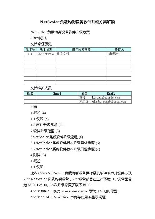
NetScaler负载均衡设备软件升级方案解读NetScaler负载均衡设备软件升级方案Citrix|思杰文档修订历史文档维护人员目录1概述 (4)1.1议题 (4)1.2软件升级需求 (4)2软件升级范围 (5)3NetScaler系统软件升级流程 (6)3.1NetScaler系统软件版本升级具体步骤 (6)3.2NetScaler系统软件版本升级回退步骤 (7)4附件 (8)1概述1.1议题此次Citrix NetScaler负载均衡设备操作系统软件版本升级共涉及2台NetScaler负载均衡设备,2台设备部署在生产环境中,设备型号为MPX 12500。
本次升级修复了以下BUG:#61018867:修改cs vserver name 导致HA切换问题;#61011174:Reporting中内存使用率显示问题;因此在此次软件版本升级中将生产环境中所涉及的2台负载均衡设备全部升级成统一的软件版本,升级后的软件版本为build-9.3-63.4.nc1.2软件升级需求一、MPX 12500软件升级需求在生产环境中使用2台MPX 12500设备,操作系统的软件版本为NS9.3: Build 60.3.nc,需要将其软件版本升级为NS9.3:build63.4.nc;两台设备采用HA主备模式。
其中一台处于Primary工作状态,另一台处于Secondary备用状态,当Primary设备出现故障时Secondary设备自动接管业务。
2软件升级范围此次软件版本升级涉及到2台Citrix NetScaler负载均衡设备。
HQxP-n01.abc 和HQxP-n02.abc为一组负载均衡资源池,设备型号为MPX 12500 设备列表如下:3NetScaler系统软件升级流程3.1 N etScaler系统软件版本升级具体步骤3.2 N etScaler 系统软件版本升级回退步骤 由于采用HA 主备模式组网架构,因此在进行操作系统软件版本升级中为了将业务影响降到最低,需要先升级备份设备,升级完成后检查备份设备的工作状态,如果状态正常则进行主备切换,以便完成另一台设备的升级工作。

目录1项目背景 (2)2 实施准备 (2)2.1 NetScaler IP准备 (2)2.2 IP地址类型: (2)3 设备的初始化进入 (2)4 配置网络路由 (6)5 license的导入 (7)6 LDAP认证服务器配置 (9)7虚拟IP配置 (13)8 配置证书请求文件 (14)9证书的生成及上传 (17)10 虚拟服务器AG的建立和配置 (22)10.1 为虚拟服务器配置profile (22)10.2 为虚拟服务器配置polices (24)10.3开始配置 (24)11 WI配置 (27)11.1 WI安装根证书安装 (28)11.2 新建一个Wi站点 (32)11.3 站点的配置 (36)12 Sslvpn配置 (39)12.1 配置vpn用户可访问的应用资源 (39)12.2 为该资源建立一个标签 (40)12.3 为VPN配置profiles (41)12.4 建立polices并与profiles建立关联 (43)12.5配置DNS (43)12.6 测试VPN访问 (48)13 邮件负载配置 (49)13.1 配置两个服务器用于负载 (49)13.2添加虚拟服务器 (51)1项目背景2 实施准备2.1 NetScaler IP准备2.2 IP地址类型:NSIP:NetScaler设备管理IP,每台设备单独拥有一个。
MIP:NetScaler与认证服务器通信,提供ADNS服务,通过MEP协议与远程站点通信IP。
VIP:虚拟AG服务器IP。
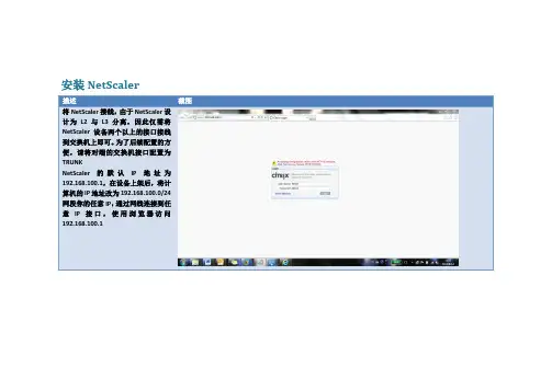
3 设备的初始化进入设备初始IP:192.168.100.1/255.255.0.0。
初始用户名密码:nsroot/nsroot。
在登陆进去后按照安装配置向导进行设备基本的配置:启用SSL功能和Access Gateway功能能启用SSL4 配置网络路由如果在初始化配置中未配置默认路由,此处需要在Network --Routes部分添加路由.5 license的导入进入System界面中点击license选项,会看见有哪些授权了哪些没授权点击下面的Manage license.选择已经购买的license—Add找到license文件后点击Select。

Netsclaer配置从CLI 配置NetScaler1. 将工作站连接至NetScaler。
A. 将随附的串行电缆插入串行端口。
B. 将串行电缆的另一端插入串行端口。
C. 运行您选择的vt100 终端仿真程序。
例如,Microsoft Windows 用户可以使用“超级终端”,它包括在Windows 的所有现代版本中。
D. 连接至NetScaler。
2. 出现登录提示时,键入用户名nsroot 和密码nsroot,然后按ENTER 键。
3. 在CLI 中键入下列命令以更改密码,然后按ENTER 键。
set system user nsroot password4. 在CLI 中键入下列命令以添加MIP,然后按ENTER 键。
add ns ip IPaddress netmask -type MIP5. 在CLI 中键入下列命令以设置默认网关,然后按ENTER 键。
add network route network netmask gateway6. 在CLI 中键入下列命令以设置NSIP,然后按ENTER 键。
set ns config -IPAddress IPaddress -netmask netmask7. 复查您所做的更改以确保它们反映您的部署目标。
8. 在CLI 中键入下列命令以保存配置,然后按ENTER 键。
save ns config9. 在CLI 中键入下列命令以重新启动NetScaler,然后按ENTER 键。
reboot参数设置端口您将串行电缆连接至的端口,通常是COM1位/ 秒(BPS) 9600数据位8奇偶校验N (无)结束位1流量控制无32 入门指南10. NetScaler 提示您确认重新启动。
键入Y,然后按ENTER 键确认重新启动。
11. 使用新的管理密码,以nsroot 身份重新登录到工作站。
12. 键入下列命令并按Enter 键以确认与NetScaler 的连接性。
某银行北京数据中心NetScaler设备硬件管理运维手册2012年12月文档修订历史文档维护人员目录1.文档目的 (4)2.硬件维护 (4)2.1.Citrix NetScaler系列设备ESD部分 (4)2.2.Citrix NetScaler系列设备Airflow部分 (5)3.常规硬件操作规范 (5)3.1.MPX 9500前面板 (5)3.2.MPX 9500后面板 (6)3.3.硬件设备安装 (6)pactFlash卡安装 (6)3.5.设备硬盘安装 (7)3.6.SFP光模块安装 (7)4.LCD液晶显示屏 (8)5.设备端口指示灯状态 (11)6.设备电源指示灯状态 (12)6.1.设备电源位置 (12)6.2.电池组模块化 (12)7.通过命令行判断硬件工作状态 (13)7.1.硬件系统工作状态 (13)7.2.接口工作状态 (14)7.3.更换电源模块 (15)7.4.更换接口模块 (16)7.5.更换风扇模块 (16)7.6.更换硬盘模块 (17)7.7.更换整机 (17)7.8.确认Console使用的波特率 (18)7.9.对单台设备进行加电操作 (18)7.10.对单台设备进行下电操作 (19)7.11.对单台设备进行重启操作 (19)7.12.冗余环境下对设备的操作 (20)1.文档目的本文档是为实现Citrix NetScaler设备硬件维护标准化的目标来制定的,目的是为了进一步规范建行硬件配置,降低硬件维护操作差异所造成的潜在网络管理风险及安全风险。
建议在阅读本文档的同时,可进一步参阅相关设备的安装指导书、白皮书等资料。
随着设备类型不断更新,运维实践的积累,这些实际情况都要求本文内容需要定期更新,以适应变化的网络环境。
2.硬件维护2.1.Citrix NetScaler系列设备ESD部分NetScaler MPX产品对静电放电(ESD)敏感。
建议当维护产品时,使用适当的ESD接地方法和设备。
标准化实施方案| 白皮书| Citrix XenDesktopPOC标准化实施指南增强功能01 NetScaler基本安装及配置版本:v2.0第1章基本过程 (3)第2章安装配置环境一览表 (3)第3章安装NetScaler VPX及初始化 (4)3.1 安装NetScaler VPX (4)3.2 基本配置 (5)第4章创建证书 (9)4.1 安装配置Windows CA服务 (9)4.2 创建Certificate Request文件(.csr) (14)4.3 创建Certificate文件(.cer) (17)第5章配置NetScaler (22)5.1 创建Access Gateway 的Virtual Server (22)5.2 创建Load Balancing 的Virtual Server (27)第6章为NetScaler创建一个专用WI站点 (30)第7章测试并验证Web Site (33)第8章变更默认的PNAgent Service site (39)产品版本 (40)修正历史 (41)第1章基本过程本章节介绍了通过NetScaler实现ica proxy的基本过程。
其包括了:∙NetScaler的安装∙Windows CA的安装∙配置NetScaler本章节开始前,请确认“PoC手册- 1 基础环境”的基础构架安装的环境均已完成。
并且确认有有效的测试NetScaler License文件供此测试使用。
另:如在PoC Runbook hands on lab培训中,请参考《PoC手册- 附录- Windows 路由器- NAT》创建一台Windows路由器以模拟内外网环境。
第2章安装配置环境一览表通过NetScaler实现ica proxy有多种实现方式,本文档只作为PoC Runbook使用,考虑到简化部署:∙不使用AG做身份认证∙NetScaler对外只有一个IP地址即Access Gateway的Virtual Server IP 当用户请求Web站点时,Access Gateway Virtual Server将把请求转给Load Balancing Virtual Server。
概述CITRIX NETSCALER常用的功能有:LB,CS,GSLB,SSL。
LB实现的功能是服务器负载均衡,CS实现基于七层(域名,IP等)的负载均衡,GSLB实现的功能是全局负载均衡,SSL实现的功能是SSL加速。
配置步骤系统配置配置feature如图:进入system菜单,选择setting点击basic feature,选中一下feature,如图:选择需要的feature,不用的都关闭点击advanced feature,选则需要的feature,不用的全部关闭修改nsroot用户的密码Netscaler默认用户名和密码均为nsroot,为了保证设备的安全性,需要修改密码,或建立新的用户。
如图:修改nsroot用户的密码,双击nsroot用户名,然后修改密码,如图:配置modeNetscaler默认是不启用2层转发的,如果需要启用2层功能,需要在mode中配置,如图:进入setting菜单,点击mode,如图:配置系统时间用shell命令进入系统的操作系统,然后用date命令修改当前系统时间输入tzsetup命令设置时区,输入date yymmddhhmm命令修改系统时间,格式为:年月天小时分钟配置时间同步用文本编辑两个文件,ntp.conf和rc.conf,内容如下:Ntp.conf:# Netscaler NTP Configuration File## Copy this file to /nsconfig, and make changes to /nsconfig/ntp.conf# Changes in /etc/ntp.conf will be lost following a reboot.## Add the following line in /nsconfig/rc.conf to enable ntpd:## ntpd_enable="YES"## The following addresses are example addresses. There should be a# corresponding 'restrict' entry for every 'server' entry.##example addressserver 61.129.42.44 burstrestrict default ignorerestrict 127.0.0.1 mask 255.255.255.255#corresponds to 'server' entry aboverestrict 61.129.42.44 mask 255.255.255.255注:61.129.42.44为ntp服务器,此类服务器在互联网上可以搜到Rc.conf:ntpd_enable="YES"编辑完两个文件后,用WinSCP3工具登陆Netscaler,然后将这两个文件拷贝到/nsconfig目录下。
Rev. 1.0.1Table of Contents1. About this Guide (3)2. Appliance Configuration Overview (3)3. Appliance Security (3)Security Mode (3)Default Passwords (4)Security Lockdown Script (4)4. Deployment Concept (4)5. One-Arm and Two-Arm Topologies (5)6. Load Balancing Methods (6)7. Appliance Deployment (7)Virtual Appliance (7)Hardware Appliance (7)Cloud Appliance (7)AWS (7)Azure (7)8. Configuring Initial Network Settings (7)Using the Network Setup Wizard (8)Using the WebUI (11)9. Accessing the Web User Interface (WebUI) (11)10. Ports Used by the Appliance (13)11. Licensing (13)12. Software Updates (13)13. Configuring & Testing a Simple Load Balanced Test Environment (14)STEP 1 – Deploy the Appliance (14)STEP 2 – Run the Network Setup Wizard (14)STEP 3 – Run the WebUI Setup Wizard (14)STEP 4 – Viewing & Modifying the Configuration (16)STEP 5 – Checking the Status using System Overview (17)STEP 6 – Verification & Testing (17)14. Configuring HA – Adding a Slave Appliance (18)15. More Information (19)16. Technical Support (19)17. Company Contact Information (20)About this Guide 1. About this GuideThis quick start guide provides enough information to deploy the appliance, configure a simple load balanced test environment and test and verify its functionality.Note:Please also refer to the Administration Manual for much more detailed information on setting up the appliance and configuring a load balanced solution. For information on configuring theappliance for specific applications, please refer to our extensive library of Deployment Guides. 2. Appliance Configuration OverviewInitial network configuration can be carried out at the console by using the Network Setup Wizard or by connecting to the default IP address & port using a browser () and makingOnce the network has been configured and the appliance has an IP address, load balanced services can be configured using the WebUI, either using the Setup Wizard (for Layer 7 services) or by manually defining the Virtual Services (VIPs) and associated Real Servers (RIPs).By default, the WebUI is accessible on HTTPS port 9443. HTTP access on port 9080 can also be enabled if required as explained in the section “Appliance Security” below.We always recommend that where possible two appliances are deployed as a clustered pair for high availability and resilience, this avoids introducing a single point of failure to your network. We recommendautomatically.3. Appliance SecuritySECURITY MODETo control how the appliance is accessed and which features are enabled, 3 security modes are provided:•Secure – this is the default mode. In this mode:◦the WebUI is accessible on HTTPS port 9443. If you attempt to access the WebUI on HTTP port 9080 you will be redirected to HTTPS port 9443◦access to the “Execute Shell Command” menu option is disabled◦the ability to edit the firewall script & the lockdown wizard is disabled◦'root' user console & SSH password access are disabled•Custom – In this mode, the security options can be configured to suit your requirements•Secure – Permanent – this mode is the same as Secure, but the change is irreversibleIMPORTANT:Only set the security mode to Secure – Permanent if you are 100% sure this is what you want!Appliance Security To configure the Security Mode:ing the WebUI, navigate to: Local Configuration > Security2.Select the required Appliance Security Mode3.If Custom is selected, configure the other options to suit your requirements4.Click UpdateNote:For full details of all options, please refer to the Administration Manual (page 80). DEFAULT PASSWORDSWe strongly recommend that default passwords are changed as soon as the appliance is deployed.1 – the 'root' Linux account:passwd2 – the 'loadbalancer' WebUI account:This can be changed using the WebUI menu option: Maintenance > PasswordsSECURITY LOCKDOWN SCRIPTThe appliance also includes a security lockdown command (lbsecure) that enables passwords to be set, network access to be locked down and SSH key regeneration in one simple step. This command can be run on a single appliance or an HA pair. For more details please refer to the Administration Manual (page 78).4. Deployment ConceptOnce deployed, clients connect to the Virtual Service(s) (VIPs) on the load balancer rather than connecting directly to one of the load balanced servers. These connections are then distributed between the load balanced servers according to the load balancing algorithm selected.Deployment ConceptNote:more information on setting up an HA pair of appliances.5. One-Arm and Two-Arm TopologiesThe number of 'arms' is a descriptive term for how many interfaces are used to connect a device to a network. It's common for a load balancer that uses a routing method (NAT) to have a two-arm configuration. Proxy based load balancers (SNAT) commonly use a one-arm configuration.One ArmIn this mode, the VIP and the load balanced servers are located in a single subnet. The load balancerrequires a single network interface adapter – eth0 in the diagram below.Note:Two ArmIn this mode, 2 subnets are used. The VIP is located in one subnet and the load balanced servers arelocated in the other subnet. The load balancer requires 2 interfaces – eth0 and eth1 in the diagram below. Note that this can be achieved by using two network adapters, or by creating VLANs on a single adapter. It's also possible to add a secondary IP address / subnet to a single network adapter.6. Load Balancing MethodsThe appliance is one of the most flexible load balancers on the market. The design allows different load balancing modules to utilize the core high availability framework of the appliance. Multiple load balancing methods can be used at the same time or in combination with each other.(*) DR mode can also be used in a multi-homed configuration where real servers are located in different subnets. In this case, the load balancer must have an interface in the same subnet to enable layer 2 connectivity which is required for DR mode to operate.KeyRecommended for high performance fully transparent and scalable solutionsRecommended if HTTP cookie persistence is required, also used for several Microsoft applications such as Exchange, Sharepoint & Remote Desktop Services and for overall deployment simplicity since real servers can be on any accessible subnet and no Real-Server changes are requiredOnly required for Direct Routing implementation across routed networks (rarely used)Recommended when you want to load balance both TCP and UDP but you're unable to use DR mode or NAT mode due to network topology or Real Server related reasonsNote:Layer 7 SNAT mode is generally the simplest most flexible method to use. As mentioned above,Note:Please refer to the Administration Manual (pages 26-32) for more detailed information on eachload balancing method.7. Appliance DeploymentVIRTUAL APPLIANCEThe VA is currently available for VMware, Virtual Box, Hyper-V, KVM, Nutanix and XEN and has been optimized for each Hypervisor. By default, the VA is allocated 1 CPU, 2GB of RAM and has an 8GB virtual disk.Note:The Virtual Appliance can be downloaded here.Note:Please refer to the Administration Manual (page 35) and the ReadMe.txt text file included in each VA download for more detailed information on deploying the VA using various Hypervisors. HARDWARE APPLIANCEFor details of all hardware models and information on installing and connecting the appliance, please refer to the Hardware Installation Guide.CLOUD APPLIANCEAWSFor details of deploying and configuring the Amazon Web Services (AWS) appliance please refer to the AWS Quick Start Guide.AZUREFor details of deploying and configuring the Microsoft Azure appliance please refer to the Azure Quick Start Guide.8. Configuring Initial Network SettingsAt power up the following startup message is displayed:By default the load balancer is pre-configured with the following IP address & subnet mask:192.168.2.21 / 24 ( equivalent to : 192.168.2.21 / 255.255.255.0 )Network settings can be changed either by running through the Network Setup Wizard as mentioned in the startup message or by accessing the WebUI on the default IP address and changing the required settings using the relevant menu options.Note:For the VA, 4 NICs are included but only eth0 is connected by default at power on. If the other NICs are required, these should be connected using the network configuration screen withinthe Hypervisor.USING THE NETWORK SETUP WIZARDThe wizard starts automatically when you log in as user 'setup'.login to the console:Username: setupPassword: setupA series of screens will be displayed that allow network settings to be configured:To continue with the Network Setup Wizardselect Yes and hit <ENTER> to continue.A list of available interfaces will be shown, hit <ENTER> to continue.Select Yes If you want to configure a bonded interface, if not leave No selected, then hit<ENTER> to continue.If you select Yes you’ll have two options:bond eth0 and eth1orbond eth2 and eth3Select Yes If you want to configure a VLAN, if not leave No selected, then hit <ENTER> to continue.If you select Yes you’ll be prompted to enter a VLAN Tag ID.Select the interface that will be used to manage the appliance, select Select and hit <ENTER> to continue.Enter the required management IP address andCIDR prefix, select Done and hit <ENTER> tocontinue.NOTE: a subnet mask such as 255.255.255.0 isnot valid, in this case enter 24 instead.Enter the default gateway address, select Doneand hit <ENTER> to continue.Define the required DNS server(s), select Doneand hit <ENTER> to continue.A summary of all settings is displayed, ifeverything looks good hit <ENTER> tocontinue, all settings will then be applied.At this stage you’ll be asked if you're recoveringfrom node (i.e. master or slave) failure.If you're simply deploying a new appliance,select No and hit <ENTER> to continue.For more details on using the Peer Recoveryfeature, please refer to the AdministrationManual (page 294).Once the wizard completes, the login prompt will be displayed along with a reminder of the new IP address and the URL to connect to the WebUI:Configuring Initial Network SettingsUSING THE WEBUIConnect to the WebUI on the default IP address as described in the section below.https://192.168.2.21:9443/lbadmin/Then use the relevant menu option to configure the various network settings:•For IP address, subnet mask, bonding and VLANs use: Local Configuration > Network Interface Configuration•For the default gateway use: Local Configuration > Routing•For DNS settings use: Local Configuration > Hostname & DNS9. Accessing the Web User Interface (WebUI)ing a web browser, access the WebUI using the following URL:https://192.168.2.21:9443/lbadmin/(replace with your IP address if it's been changed)Note:2.Login to the WebUI:Username: loadbalancerPassword: loadbalancerNote:To change the password, use the WebUI menu option: Maintenance > Passwords.Accessing the Web User Interface (WebUI) Once logged in, the WebUI will displayed as shown below:The WebUI for the VA is shown. The hardware and cloud appliances are very similar, but have different startup messages (shown yellow above).1.Once logged in, you'll be asked if you want to run the web based setup wizard. If you click Acceptthe Layer 7 Virtual Service configuration wizard will start (please refer to page 14 for details of using the wizard). If you want to configure the appliance manually, simple click Dismiss.Main Menu Options:System Overview – Displays a graphical summary of all VIPs, RIPs and key appliance statistics Local Configuration – Configure local host settings such as IP address, DNS, system time etc.Cluster Configuration – Configure load balanced services such as VIPs & RIPsMaintenance – Perform maintenance tasks such as service restarts and taking backupsView Configuration – Display the saved appliance configuration settingsReports – View various appliance reports & graphsLogs – View various appliance logsSupport – Create a support download, contact the support team & access useful linksPorts Used by the Appliance 10. Ports Used by the ApplianceBy default, the appliance uses the following TCP & UDP ports:11. LicensingThe trial runs for 30 days and is completely unrestricted during this time. After 30 days, the appliance continues to work but it's no longer possible to make changes to the configuration. If you need more time to complete your evaluation, please contact ********************** who will be able to provide guidance on how to extend the trial using a simple command.When a license is purchased, you'll be provided with a license key file by our sales team. You can then simply apply this license to your appliance.To install the license:ing the WebUI, navigate to: Local Configuration > License Key2.Browse to the license file provided when the appliance was purchased3.Click Install License Key12. Software Updates continually develop and add new and improved features to the appliance. These updates can be applied during the trial to ensure you have the very latest version of our software for your evaluation.To run Software Update:ing the WebUI, navigate to: Maintenance > Software Update2.Choose Online Update if the appliance has Internet access3.If updates are available, you'll be presented with a list of changes, click the Online Update buttonat the bottom of the page to start the updateNote:If your appliance does not have Internet access, please contact ************************ fordetails of how to obtain the offline update files.13. Configuring & Testing a Simple Load Balanced Test EnvironmentThis example illustrates how to quickly configure a simple load balanced test environment using the Network Setup Wizard at the console to configure network settings, and the Setup Wizard from the WebUI to configure the layer 7 virtual service.Note:Layer 7 SNAT mode is used in the example. As mentioned earlier, this is not the fastest mode but is very simple to deploy and requires no changes to the Real Servers.The following table and diagram describe the environment:STEP 1 – DEPLOY THE APPLIANCE•STEP 2 – RUN THE NETWORK SETUP WIZARD•STEP 3 – RUN THE WEBUI SETUP WIZARD1.Open the WebUI and start the wizard by clicking the Accept button, or by using the WebUI menuoption: Cluster Configuration > Setup Wizard and clicking General Layer 7 Virtual Service2.Define the required Virtual Service settings as shown in the example below:3.Click Create Virtual Service4.Now continue and add the associated load balanced servers (Real Servers) as shown below:•Use the Add Real Server button to define additional Real Servers and use the red cross to delete Real Servers•Once you're happy, click Attach Real Servers to create the new Virtual Service & Real Servers• A confirmation message will be displayed as shown in the example below:5.Click Continue6.Finally, reload HAProxy using the Reload HAProxy button in the blue box at the top of the screen orby using the WebUI menu option: Maintenance > Restart Services and clicking Reload HAProxyNote:Running the wizard again will permit additional Layer 7 VIPs and associated RIPs to be defined.Note:To restore manufacturer's settings use the WebUI menu option: Maintenance > Backup &Restore > Restore Manufacturer's Defaults. This will reset the IP address to 192.168.2.21/24.Note:By default Real Server health-checks set as a TCP port connect. If you need a more robustcheck, this can be changed by modifying the configuration as explained below. Please refer tothe Administration Manual (page 201) for more information on configuring health-checks. STEP 4 – VIEWING & MODIFYING THE CONFIGURATION1.The VIP created by the wizard can be seen using the WebUI menu option: Cluster Configuration >Layer 7 – Virtual Services as shown below:2.Clicking the Modify button allows all VIP setting to be modified3.If changes are made, click the Update button to save the changes, then use the Reload HAProxybutton at the top of the screen to apply the changes4.Additional VIPs can be added by running the Setup Wizard again, or by clicking the Add a newVirtual Service button to define the VIP manuallyReal Servers can be added manually using the WebUI menu option: Cluster Configuration >Layer 7 – Real Servers.STEP 5 – CHECKING THE STATUS USING SYSTEM OVERVIEWing the WebUI, navigate to: System Overview to view the newly created VIP & RIPs:2.To view the RIPs, click anywhere on the horizontal gray area to expand the VIP as shown below:STEP 6 – VERIFICATION & TESTING1.Verify that both Real Servers are up. In the example below, Web2 is failing its health-check:•This should be investigated and corrected, possible steps include:◦Check that the application/service is running on the Real Server◦Make sure you can ping the Real Server from the load balancer◦Verify that you can connect to the application port from the load balancer. This can be done using telnet at the console or via an SSH session:telnet 192.168.1.40 802.Once both servers are up (shown green) browse to the VIP address and verify that you see the webpage from each Real Server:•Halt Web1 using the Halt option for Web1 in the System Overview and verify that content is served by Web2 on a browser refresh (CTRL-F5)•Halt Web2 using the Halt option for Web2 in the System Overview and verify that content is served by Web1 on a browser refresh (CTRL-F5)Please refer to the Administration Manual (page 246-261) for more configuration examplesusing Layer 7 SNAT mode and also Layer 4 DR mode, Layer 4 NAT mode & Layer 4 SNAT mode.Note:For more information on verifying your test environment and ways to diagnose any issues youhave, please also refer to Chapter 12 – Testing Load Balanced Services in the AdministrationManual (page 263 – 268).14. Configuring HA – Adding a Slave ApplianceAs mentioned earlier, our recommended configuration is to use a clustered HA pair of load balancers to provide a highly available and resilient load balancing solution. We recommend that the master is fully configured first, then the slave should be added. The clustered HA pair uses Heartbeat to determine the state of the other appliance. Should the active device (normally the master) suffer a failure, the passive device (normally the slave) will take over.To add a slave node – i.e. create a highly available clustered pair:1.Deploy a second appliance that will be the slave and configure initial network settingsing the WebUI, navigate to: Cluster Configuration > High-Availability Configuration3.Specify the IP address and the loadbalancer users password (the default is 'loadbalancer') for theslave (peer) appliance as shown above4.Click Add new node5.The pairing process now commences as shown below:Configuring HA – Adding a Slave Appliance6.Once complete, the following will be displayed:7.To finalize the configuration, restart heartbeat and any other services as prompted in the bluemessage box at the top of the screenNote:Clicking the Restart Heartbeat button on the master appliance will also automatically restartheartbeat on the slave appliance.Note:Please refer to the Administration Manual (page 221-234) for more detailed information onconfiguring HA with 2 appliances.15. More InformationPlease refer to our website for the latest administration manual, deployment guides and all other documentation: https:///support/manuals/.16. Technical SupportIf you have any questions regarding the appliance or how to load balance your application, please don't hesitate to contact our support team using the following email address: ************************Company Contact Information 17. Company Contact InformationWebsite URL:w w North America (US), Inc.4550 Linden Hill Road, Suite 201Wilmington, DE 19808USATel: Email (sales): Email (support):+1 833.274.2566********************** ************************North America (Canada) Appliances Ltd.300-422 Richards StreetVancouver, BCV6B 2Z4CanadaTel: Email (sales): Email (support):+1 866.998.0508********************** ************************Europe (UK) Ltd.Compass HouseNorth Harbour Business ParkPortsmouth, PO6 4PSUKTel: Email (sales): Email (support):+44 (0)330 380 1064********************** ************************Europe (Germany) GmbHTengstraße 2780798MünchenGermanyTel: Email (sales): Email (support):+49 (0)89 2000 2179************************* ************************。
服务器负载均衡(LB)的配置手册
1、设置设备的访问IP(NSIP)和SNIP(用于和服务器连接)
点击上图的1.按照步骤设置,设置如下:
注:设置完成后重启设备
2、修改用户名和密码
在步骤4中输入nsroot这个用户的新密码即可。
3、设置用户名和密码
注:第四步中的四个权限operator是一般的操作员,
read-only只读权限,network为网络查看权限(只读权限)
3、服务器负载均衡的设置步骤
3.1、添加服务
注:第一步:选择服务;第二部添加服务;第三步,设置服务的名称;第四步,添加需要做负载的服务器的地址;
第五步,选择服务器的协议;第六步,设置服务器的服务的端口号;第七步,选择服务器健康检查;第七步,添加健康检查。
3.2、添加虚拟服务器
注:第一步,选择虚拟服务器;第二步,添加虚拟服务器;第三步,添加虚拟服务器名称;第四步,选择虚拟服务器的协议;第五步,选择虚拟服务器的地址(此地址是负载之后访问的入口地址);第六步,设置虚拟服务器的端口号;第七步,选择需要做负载的服务器;第八步和第九步,选择虚拟服务器转发请求的规则,此处选择的是根据服务器的最少的连接转发请求。
3.3请求转发的比重
注:设置权重,如上图,在相同情况下,权重是2的处理
请求的数量是权重是1的服务器的2倍。
Citrix负载均衡设备10.1配置手册XXXX-XX-XX发布 XXXX-XX-XX实施目录前言 (V)范围.................................................................................................错误!未定义书签。
第一章总体设计.........................................................................错误!未定义书签。
1.1安装部署规范示意图 .............................................................. 错误!未定义书签。
1.2负载均衡设备位置及名称 ...................................................... 错误!未定义书签。
1.3地址分配 .................................................................................. 错误!未定义书签。
第二章环境配置要求 (6)2.1软件版本许可功能要求 (6)2.2相关操作系统版本要求 (6)第三章设备初始化配置规范 (6)3.1前期准备工作 (6)3.2初始化设备连接 (7)3.3安装L ICENSE (12)3.4操作系统升/降级 (15)3.5基本选项配置 (23)3.5.1设备名称设置 (24)3.5.2管理IP(NSIP)地址设置 (26)3.5.3系统时区配置 (28)3.5.4修改系统管理员登录密码 (29)3.6系统功能特性配置 (30)3.7CLI超时时间配置 (35)第四章系统配置规范 (37)4.1高可用配置 (37)4.1.1配置高可用 (37)4.1.2配置同步 (40)4.1.3主备切换 (41)4.2NTP配置规范 (43)4.3SNMP配置规范 (45)4.4SYSLOG配置规范 (49)4.5A UDIT配置 (54)4.6系统用户配置规范 (57)4.6.1 SYSTEM USER配置 (57)4.6.2用户认证服务器配置 (59)4.7配置备份和恢复 (65)第五章网络配置规范 (66)5.1配置管理IP(NSIP)地址 (66)5.2配置SNIP (70)5.3配置缺省路由 (72)5.4配置C HANNELS (73)5.4.1手动配置静态链路聚合 (74)5.4.2接口动态LACP配置 (76)5.5配置端口HA M ONITOR (79)5.6配置VLAN (81)5.7配置静态路由 (85)5.8配置NAT (88)第六章负载均衡虚拟服务器(VS)配置规范 (91)6.1新建/删除LB S ERVER (92)6.2配置LB M ONITOR (94)6.3配置S ERVICE G ROUP (99)6.4配置LB V SERVER (107)6.5V IRTUAL S ERVERS常见参数配置 (116)6.5.1插入客户端IP地址到HTTP头部 (116)6.5.2TCP长连接超时设置 (118)第七章PROFILE配置规范 (119)7.1TCP P ROFILE配置 (119)7.1HTTP P ROFILE配置 (126)7.1N ET P ROFILE配置 (131)参考文献 ........................................................................................错误!未定义书签。