一体化云台枪型摄像机手册
- 格式:pdf
- 大小:623.50 KB
- 文档页数:22
摄像机云台控制说明书摄像机云台控制说明书1:接好摄像机电源,确定摄像机启动正常。
2:接好视频连接线,并连接到电脑的采集卡,确定摄像机视频正常显示。
3:接好控制线,控制线一端连接到电脑的串口(COM),一端连接接到摄像机的RS232控制接口,以下是各个摄像机的RS232接口图(红色框部分表示RS232接口):麦德(TAC20P)威克(MCC-D80)05、SW1 地址拨码开关 06、VIDEO 视频插孔 07、RS232插孔 08、SW2协议、波特率、图像翻转拨码 09、DC IN 12V 电源插孔 10、RS485/RS422插孔4:设置摄像机的ID:A:为什么要设置摄像机ID?一条控制线是可以控制多个摄像机的,而唯一区别摄像机的就是摄像机的ID,所以在控制多个同一个协议的摄像机的时候,摄像机ID就起作用了,若不控制多个,建议就用默认的ID为0;B:怎样设置摄像机ID?首先查看摄像机的说明书,看摄像机上有没有设置摄像机ID的开关,比如:麦德的摄像机就没有ID设置,默认就为0,威克的ID开关是SW1,如上面的图中05拨码开关设置摄像机拨码开关位图如下表。
LSB MSBSW1 SW2可以通过设置8位拨码开关SW1来设定地址的编码。
地址码设定采用二进制方式,共可以设置256个不同的摄像机地址。
设置好摄像机上的ID后,在软件里面打开“设置”菜单的“视频设置”对摄像机设置相应的ID,如下图:5:设置串口协议、波特率:首先查看摄像机说明书或向购买厂商咨询此摄像机支持那些控制协议,目前我们支持的有麦德的TAC20P,SONYD70/D100摄像机协议,还有比较通用的PELCO-P、PELCO-D协议,威克的MCC-D80就支持这2种协议。
知道摄像机的协议后,看摄像机上面有没有设置协议的开关,因为有的摄像机支持多种协议,一定有开关来设置的,比如威克的摄像机:如上面设置ID一样,8位拨码开关SW2为模式选择开关,可设置波特率、通讯协议、图像正向/翻转。
网络摄像机用户使用手册V1.4--目录--..............................................................................--2-第一章产品简介..............................................................................1.1主要功能及特点 (2)1.2主要应用 (3)......................................................................................--3-第二章安装......................................................................................2.1注意事项 (3)2.2面板及说明 (4)2.2.1侧面图 (4)2.2.2后面板图 (5)2.3硬件安装 (7)2.3.1网络拓扑图 (7)2.3.2报警输入连接说明 (7)2.3.3报警输出连接说明 (8)2.3.4网线的制作 (9)..............................................................................--9-第三章参数配置..............................................................................3.1通过IE浏览器进行参数配置 (10)附录 (11)本手册适用于枪机系列第一章产品简介网络摄像机是集传统的模拟摄像机和网络视频服务器于一体的嵌入式数字监控产品。
采用嵌入式Linux操作系统和高端SOC硬件平台,系统调度效率高,代码固化在Flash中,体积小,具有较高稳定性和可靠性。
网络高清智能高速云台摄像机中文使用手册在使用本产品之前,敬请您仔细阅读使用手册!安全提示: 注意防止触电危险.请不要打开!注意:为了减少触电危险,请勿自行拆卸。
里面没有用户自己可修理的零件。
应由有资格的人员进行维修工作。
!在正三角形中闪烁的箭头符号,用以提醒用户在本产品中附近出现较大的“非绝缘危险点电压”,足以对人体产生危险。
在正三角形中的注意号,用以提醒用户参考有关该机的重要操作与维护的文字说明。
本产品的制造号标示于底部或侧面。
请在下面空白处填上本机的制造号码,并将此说明书妥善保存,以便需要时查核。
型号:制造号码:V2.0 ,用以提醒用户参考有关该机的重要操作与维护的文字说明。
!目录注意事项 (1第一章功能特点 (3 1.1 云台规格 (31.2 云台基本参数 (3 1.3 云台报警 (31.4 网络参数 (41.5 云台功能 (6第二章网络设臵 (7 2.1 系统连接图 (7 2.2 登录网络 (82.3 预览视频 (10 2.4 设备参数 (15 2.5 语音对讲 (29 2.6 文件管理 (29 2.7 远程回放 (32 2.8 本地设臵 (362.9 设备录像 (373.0 注销重启 (37第三章云台设定 (383.1 系统连接 (383.2 云台拨码设定 (383.3 协议和默认波特率选设定 (403.4 通信波特率的设定 (41第四章安装说明 (434.1 安全措施 (434.2 警告 (434.3 环境要求 (444.4 布线安全 (444.5 安装准备 (444.6 安装方式简介 (464.7 安装说明 (464.8 云台的出线说明 (50附录Ⅰ:系统参数表 (52附录Ⅱ:常见故障分析 (58附录Ⅲ:24VAC 线径和传输距离关系表 (59 附录Ⅳ:防雷击、浪涌 (61附录Ⅴ:维修服务条款 (62注意事项:电气安全在本产品安装使用中必须严格遵守国家和地区各项电气标准。
配用本机自带的专用电源。

枪型网络摄像机快速入门资料版本:V2.03BOM:3101C02X负责安装和日常维护本设备的人员必须具备安全操作基本技能。
在操作本设备前,请务必认真阅读和执行产品手册规定的安全规范。
安装使用注意事项当光模块工作时,请不要直视光模块和光纤接头(适用于激光接口设备)。
为避免火灾及电击危险,使用时请勿让水或其它液体流入设备。
移动设备之前请断开电源,移动时应小心防止触电,一旦电源线插入电源,设备即会通电。
实际安装时需要使用到一些支架,比如壁装支架、吊装支架等,安装时尽量远离振动源;若您需要提高防护等级,则可将摄像机安装在护罩中。
请您参考本公司的配件推荐表来选择合适的支架和护罩。
若在高空、空旷、风力较大地方安装枪机及护罩,建议在立柱上焊接安装平台(不推荐使用壁装支架转接),并配合大万向节使用,以提高整体安装刚度,避免枪机因风吹产生振动,导致图像抖动。
使用符合要求的电源适配器或PoE供电设备,使用不符合要求的电源适配器有可能造成摄像机受损。
若电源适配器与设备之间的电源线过长,会导致到达设备的电压偏低,容易造成设备工作异常。
若您需要对电源线加长,请参见“电源线要求”。
现场安装过程中,要求尾线(电源线、网口线)不能过度弯折,避免长时间应力作用导致线缆接触不良,影响设备使用。
请确认在断电状态下连接电源适配器和摄像机,严禁将适配器先上电再连接摄像机,严禁在适配器上电时拔下设备侧电源线。
连接告警输入接口时,请保证告警输入的高电平信号不超过5V DC。
对外连接端口,请用既有的电缆端子进行连接,连接时,请确认电缆端子(锁扣/卡扣)良好,并紧固到位;安装过程中电缆拉扯不要过度,保持有一定余量,防止因为振动、晃动导致端口接触不良或松脱。
日常维护注意事项镜头、护罩前脸无污斑,轻度沾灰时,请使用无油软刷轻轻弹落或吹风皮球吹落。
镜头沾染油脂时,将油污用无油棉布轻轻拭去,再用无油棉布或镜头清洁纸蘸上少量镜头清洁液,自镜头中心轻轻向外旋转擦拭。
防爆一体化云台摄像仪使用说明书V1.0.2浙江大华技术股份有限公司防爆标志:Ex d IIC T6 Gb/Ex tD A21 IP68 T80℃前言概述本文档详细描述了防爆一体化云台摄像仪的产品概述、安装、连接、使用等内容。
符号约定在本文档中可能出现下列标识,代表的含义如下。
标识说明表示有中度或低度潜在危险,如果不能避免,可能导致人员轻微或中等伤害。
表示有潜在风险,如果忽视这些文本,可能导致设备损坏、数据丢失、设备性能降低或不可预知的结果。
表示是正文的附加信息,是对正文的强调和补充。
修订记录版本号修订内容发布日期V1.0.2 删除敏感词汇。
2020.11V1.0.1 更新模板。
更新公司。
2020.09V1.0.0 首次发布。
-装箱清单开箱之后请仔细核对包装箱内设备及配件,如有异样及缺失,请及时与当地供应商或公司客服部(400-672-8166)联系,产品实时更新,如有更改,恕不另行通知。
如有任何疑问或争议,请以公司最终解释为准。
序号名称数量备注1 防爆一体化云台摄像仪 1 -2 遮阳罩 1 -3 使用说明书 1 -4 产品合格证 1 -5 M10×45内六角圆柱头螺钉、平垫、弹垫、螺母5套用于安装一体化摄像仪6 M3、M10内六角扳手各1 安装产品、调试雨刷用7 防爆挠性管 1 1米使用安全须知感谢您选用本公司的防爆产品!安装、使用前请仔细阅读本手册,遵守警告事项,并妥善保存好本手册。
质量保证对于本公司生产的防爆一体化云台摄像仪在产品保修期内,本公司提供免费维修服务,但如有以下情形者,将酌情收取材料成本工时费用:●不按照使用说明书中的规定进行操作导致损坏。
●擅自拆机导致损坏。
●雷击及不可抗拒的自然灾害。
若公司与用户之间另有书面服务承诺或规定,将严格按照承诺或规定的要求进行处理。
安全保证该设备的运行符合以下两个条件:●设备的运行不会产生有害的干扰。
●设备的运行在一定程度上不受外部干扰,甚至是不良干扰的影响。
一体化云台摄像机用户手册(V4.2)◆安装使用前,请仔细阅读手册并妥善保存目录1.注意事项-----------------------------------------------------------------2 2.产品介绍-----------------------------------------------------------------4主要部分说明-----------------------------------------------------------4 技术参数-----------------------------------------------------------------5外形尺寸-----------------------------------------------------------------6 安装方式-----------------------------------------------------------------6连接方法-----------------------------------------------------------------7 3.地址码设置--------------------------------------------------------------7 4.协议码设置--------------------------------------------------------------9 5.云台波特率设置-------------------------------------------------------10 6.像机拨码选择设置----------------------------------------------------10 7.操作说明----------------------------------------------------------------11 8.球机OSD菜单操作---------------------------------------------------15 9.红外灯筒的安装-------------------------------------------------------31 10.常见故障排除及解决方法-------------------------------------------34 11.售后服务----------------------------------------------------------------3511.注意事项1.不要擅自拆卸摄像机不要卸下螺钉或防护盖,以免触电。
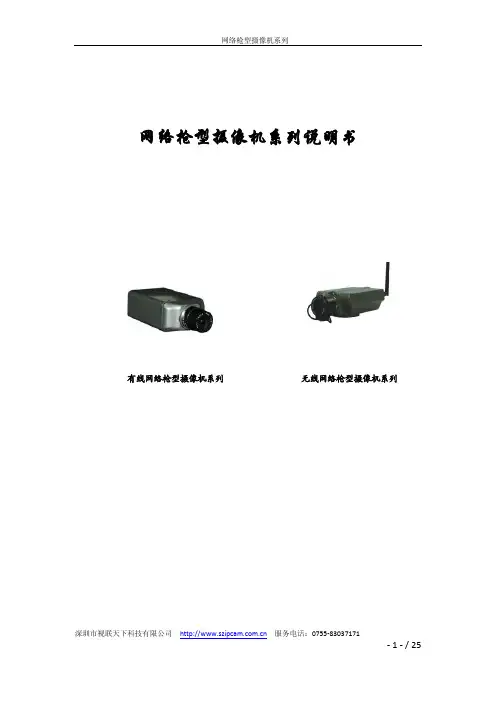
深圳市视联天下科技有限公司 服务电话:*************网络枪型摄像机系列说明书有线网络枪型摄像机系列 无线网络枪型摄像机系列目录一.前言说明............................................................................................................ - 3 -二.产品简介............................................................................................................ - 3 -2.1.外观尺寸 ..................................................................................................... - 3 -2.2.产品特点 ..................................................................................................... - 3 -三.产品安装............................................................................................................ - 4 -3.1.客户端系统要求 ......................................................................................... - 4 -3.2.安装注意事项 ............................................................................................. - 4 -3.3. 维修申明 ................................................................................................... - 5 -3.4.安装枪型摄像机 ......................................................................................... - 5 -四.快速网络连接拓扑图........................................................................................ - 5 -4.1.直接连接到PC机(通过交叉网线) ....................................................... - 5 -4.2.通过HUB/Switch连接局域网 .................................................................... - 6 -4.3.通过HUB/Switch/路由器连接广域网 ....................................................... - 6 -4.4备注 ............................................................................................................. - 7 -五.访问网络摄像机主页........................................................................................ - 7 -5.1.在浏览网络摄像机主页前请操作以下事项 ............................................. - 7 -5.2.登录网络摄像机 ......................................................................................... - 7 -5.2.1系统设置 .......................................................................................... - 8 -5.2.2音视频设置 ....................................................................................- 10 -手机监控具体说明:..............................................................................- 11 -操作方式:..............................................................................................- 11 -在智能手机上播放..................................................................................- 11 -5.2.3网络设置 ........................................................................................- 12 -5.2.4报警设置 ........................................................................................- 13 -5.2.5维护与升级 ....................................................................................- 16 -5.2.6录像回放 ........................................................................................- 16 -5.2.7控制区说明 ....................................................................................- 16 -5.3注意事项 ...................................................................................................- 17 -六.远程访问图像设置.............................................................................................- 17 -6.1 静态IP访问 .............................................................................................- 17 -6.2 动态IP访问 .............................................................................................- 17 -七.产品技术参数..................................................................................................- 20 -八.常见问题及解决方法......................................................................................- 23 -九.保修说明.............................................................................................................- 24 -9.1售后服务规定 ...........................................................................................- 24 -9.2如果出现以下情况不实现“三包”服务 ...............................................- 24 -9.3备注 ...........................................................................................................- 24 -深圳市视联天下科技有限公司服务电话:*************深圳市视联天下科技有限公司 服务电话:*************一.前言说明感谢您使用本公司研发.生产一系列视频监控产品,此说明书仅为指导客户简易的安装及使用网络摄像机,为了保障本产品的正常使用及其寿命,请不要拆开或改装本机,否则对其造成的后果不予更换或保修。
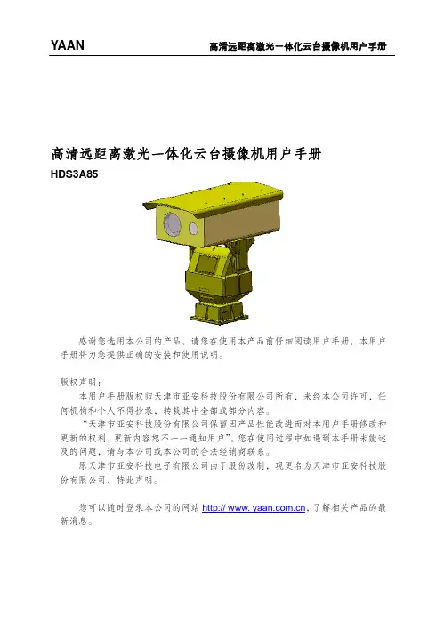
高H高清远距离HDS3A85 感谢您选手册将为您提版权声明:本用户手何机构和个人“天津市更新的权利,及的问题,请原天津市份有限公司,您可以随新消息。
离激光一体 选用本公司的产提供正确的安装手册版权归天津人不得抄录,转市亚安科技股份更新内容恕不请与本公司或本市亚安科技电子特此声明。
随时登录本公司 体化云台摄产品,请您在使装和使用说明。
津市亚安科技股转载其中全部或份有限公司保留一一通知用户”本公司的合法经子有限公司由于的网站http:// 摄像机用户使用本产品前仔 股份有限公司所部分内容。
因产品性能改”。
您在使用过销商联系。
股份改制,现www. yaan.co 户手册细阅读用户手册有,未经本公进而对本用户程中如遇到本更名为天津市 ,了解相 册,本用户司许可,任手册修改和手册未能述亚安科技股关产品的最目录1 安全注意事项 (1)1.1警告 (1)1.2注意 (2)2 产品介绍 (4)2.1产品应用 (4)2.2术语 (4)2.3产品特点 (5)2.4技术参数 (6)3 安装 (7)3.1安装前确认 (7)3.2安装准备 (8)3.3开始安装 (12)3.4通电测试 (15)4 云台特殊功能 (16)附录一简易故障维修 (18)定期检查 (19)1.1 警告1.1.1 安装和使用本设备之前,请仔细阅读说明书,并妥善保管,以便日后使用。
1.1.2 应遵守产品上和说明书上的所有警告事项,遵守全部指示操作和使用说明。
1.1.3 在擦拭产品之前,先断开电源,勿用液体或喷雾式清洁剂,请用湿布擦拭。
1.1.4 应使用经销商或我公司推荐的配件,否则可能会导致故障。
1.1.5 本产品应使用用户手册规定的电源种类和电压,如安装地点的电源和电压不明确,请与经销商或我公司联系。
1.1.6 应妥善保护电源线,插头和摄像机线缆线。
1.1.7 云台RS-485及视频信号采用防雷管和TVS瞬变技术,可以有效地防止2000伏以下的雷击、浪涌等各类脉冲信号对设备造成的损坏,电源采用自恢复保险和压敏电阻,可以有效地防止雷击。
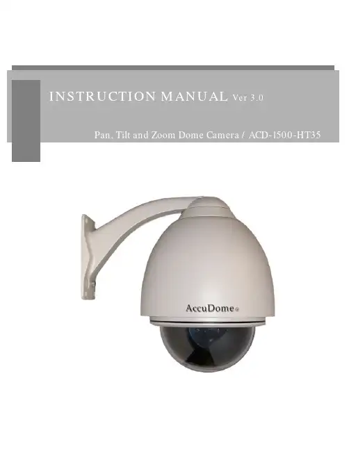
1 IntroductionFeatures 3Components 4System Configuration 52 RS485 and PTZ BasicsPhysical Connection 6Multiple PTZ Setup 7ID, Protocol, Baud Rate 93 InstallationWall Mount 10Ceiling Mount 11Final Assembly 124 Camera AddressingCamera Address Setting 13 Protocol and Baud Rate Settings 155 Basic FunctionsSelecting Camera16Setting Presets17Calling Presets17Clearing Presets17Auto Cruise18Auto Pan186 Advanced FunctionsCamera Reboot 19Back Light Compensation 19Digital Zoom 19Focus Mode 19Iris Mode 20Auto White Balance 20 Low Light/IR Sensitive Mode 207 On Screen DisplayNo OSD 218 Parts Description and Function 229 Product Specifications 23Camera Specification• Hitachi Module 540 Lines• Progressive Scan• 35X Optical Zoom• 12X Digital Zoom• 3.4mm – 119mm Zoom• Digital Slow Shutter (DSS)• Wide Dynamic Range (WDR)• Electronic Image Stabilizer (EIS)• Removable IR Cut Filter• Low Lux (.01)• IR Sensitive• 24v ACComplete View• 360 Degree Pan, 90 Degree Tilt. For No Blind SpotsHousing• Indoor / Outdoor use, Weather Proof Housing• Multiple Mounting Configurations• Operating Temperatures: -31° to 131° FPTZ Control• RS-485 Communication, MAX 31 Multi-drop• Versatile Pelco-D and Pelco P Protocol• Variable Pan and Tilt Speed• 64 Programmable Presets• OSD Setup• Programmable Cruise SequenceParts InformationItemPart No. DescriptionDome Camera and HousingACD-1500-HT35NTSC Dome Camera, Weather Proof Housing, Including TransparentDomeWall Mount Bracket Bracket for mounting PTZ to Wall Pendant Mount Bracket Bracket for mounting PTZ to Ceiling Mounting Screws & WrenchAllen Screws for mounting PTZ to MountPower Supply24v AC Power SupplyManualManual for ACD-1500-HT35Default ComponentsDome Camera and HousingWall Mount BracketCeiling Mounting BracketConfigurationPart Description• MountUsed to install Camera Housing• HousingProtects Internal Components From the Elements •Polycarbonate Dome Protects PTZ Camera• Wiring Access Allows access to internal wiring • Built in HeatersKeeps lens clear in cold weatherWiring AccessMountHousingPolycarbonateDome(Camera inside)Video OutputBlueNet Video serverBlueNet Video serverDVR DVRPTZ Controller MonitorRS-485 InputRS-485 communicationRS-485 communication is used to control a PTZ camera. Standalone DVRs, PC-based DVRs, keyboard joystick PTZ controllers, video servers, and a variety of other CCTV equipment usually have an RS-485 interface (push terminals, D-Sub connector, etc.) for PTZ control. The CCTV equipment transmits control signals while the PTZ camera receives the signals and performs the function required.RS-485 utilizes two wires ; a ‘+’ wire and a ‘–’ wire. These two wires may also be label or reference as:• + and – • D+ and D- • A+ and B-•RS485+ and RS485-To make the physical connection from the controlling device (DVR, keyboard controller, etc.) to the PTZ, simply connect the RS485 ‘-’ from the controlling device to the RS485 ‘-’ on the PTZ. Do the same for the RS485 ‘+’. Any type of wire can be used for the connection, but 0.56mm (24AWG) twisted pair is recommended.++-- PTZ Physical ConnectionsControllerBaud Rate is the data transmission rate in bps (bits per second). Both the controlling device and PTZ must use the same baud rate. Most PTZ camera and devices default to a baud rate of 2400 bps.The maximum theoretical transmitting distances of RS-485 are below using 0.56mm (24AWG) twisted pair cable.Baud Rate Maximum Distance2400 bps 1800m 4800 bps1200m9600 bps800mIf thinner cables are used or the dome is installed in an environment with strong electromagnetic interference or many PTZs are used on the same line, the maximum distance will be decreased.For multiple PTZ installs , RS485 standards require a daisy-chain connection between the equipment. Up to 32 devices, including the controller can be daisy-chained. A 120 Ω termination must be made on the first and last device in the chain. Most controllers are already terminated. To terminate the last PTZ in line, simply locate the 120 Ω termination resistor jumper on the PTZ’s protocol PCB and set the jumper to pins 1 & 2. By default, the PTZ is not terminated, thus having the pins on 2 & 3. For Star Configurations, see the next page.Termination Jumper Location.Continued on Next PageMultiple PTZ (cont.)Some circumstances require the use of a star configuration. The termination resistors must be set on the two devices that are the farthest distances away from each other, in this case #1 and #15 as seen below.As the star configuration does not conform to the RS485 standards, problems such as signal reflection and lower anti-interference performance arise when the cable runs are long. In addition, the reliability of control signals are decreased which may cause the PTZ to respond intermittently, not respond at all, or operate a single command continuously without ever stopping. In these circumstances, the factory recommends the use of an RS485 distributor (DR-HB16). The distributor can change the star configuration connection to the mode of connection stipulated in the RS485 standards. With the distributor, reliable data transmission can be received.PTZ Addressing and Communication ProtocolBefore installing PTZs, you must understand 3 things:CameraID-PTZProtocol-PTZ-PTZ Baud RatePTZ Camera ID - Each PTZ camera in an install must have a unique ID number assigned. MostPTZs default to ID#1. The PTZ controller must be told what PTZ camera tocontrol, and this ID number is called to control the corresponding camera. ThePTZ ID number can be set to any number 1 – 1023.PTZ Protocol - All PTZ controllers and cameras need to support a common communicationlanguage in order to send/receive control commands. This language is called aprotocol. The protocol set in the PTZ camera must match the protocol set in thecontroller. Below is a list of commonly supported protocols.•Pelco-D•Pelco-P•Santachi•Hunda600•LongcomityPTZ Baud Rate - Baud Rate is the data transmission rate in bps (bits per second). Both the controlling device and PTZ must use the same baud rate. Most PTZ cameras anddevices default to a baud rate of 2400 bps.Wall Mount Installation using Outdoor Housing Assembly1) Attach the Wall Mount Bracket to the wall.Make sure the wall can support the weight and vibration of the camera and housing.2) Remove thumb screw holding access cover inplace on Mounting Arm.3) Route the wiring through the inside of the armand out the access hole.4) Assemble and screw the Outdoor HousingAssembly on the Mount Bracket while routing the wiring from the camera through the neck of the bracket and out the access hole.Continue to page 11Ceiling Mount Installation using Outdoor Housing Assembly1) Mount the Top Ceiling Mount Bracket to theCeiling. Make sure the Ceiling can support the weight and vibration of the camera and housing.2) Route the wiring through the bottom CeilingMount Bracket and Extension.3) Attach assembly to the PTZ camera using theincluded Allen Screws. Tighten set screws.4) Align the PTZ Assembly into the top of theceiling mount. Turn clockwise to thread extension into mount. Tighten set screws.Continued on Next Page5) Unscrew Polycarbonate dome cover counter-clockwise.6) Remove BLACK camera cover inside ofhousing.7) Set DIP switches according to Protocol andBaud rate desired. (See page 13 for details)8) Replace BLACK camera cover andPolycarbonate dome cover.RS-485 communicationRS-485 communication is used to control the camera. RS-485 utilizes two wires, + and -. Protocol, Baud rate and Camera Address are also required and are set using 2 sets of Dip Switch sets under the BLACK camera cover inside the PTZ housing (see page 12). Each camera connected to the PTZ controller must have a unique address.•SpecificationStandard RS-485 with MAX. 31 Camera Control • Number of wire 2 Wire (D+, D-)• Protocol Pelco-D, Pelco-P, A01, B01, Santachi, Longcomity and HUNDA600SW 1 : Camera Address SettingsON1 2 3 4 5 6 7 8 9 10• Factory Default ID is 1• The dip switches are equivalent to 10-bit binary. Examples are listed on the next page.SW 1 : Camera Address Settings (continued)When using more than 1 RS-485 device each unit must be given a unique address. Refer to the chart on the previous page for the value of each dip switch. For each dip switch that is ON the value/values are added together, the total is the address of that unit.For Example:For an address of 1:Dip switch #1 (value = 1) will be ON all others OFFFor an address of 5:Dip switch #1 (value = 1) & #3 (value = 4) will be ON all others OFFFor an address of 157:Dip Switch #1 (value = 1), #3 (value = 4), #4 (value = 8), #5 (value = 16), #8 (value =128) will be ON all others OFFSW 2 : Camera Protocol and Baud Rate SettingsThis camera supports multiple RS-485 Protocols and Baud Rates which can be set using the SW2Dip switch located under the BLACK camera cover. The table below contains a list of protocols supported by the camera and the default baud rate for the protocol.Selection Of ProtocolsDefault BaudRatesSupported Protocol1st2nd 3rd 4th 5th 6th Pelco D /2400 ON ON OFF OFF OFF OFF Pelco P /4800 OFF OFF ON OFF ON OFF Pelco P /9600 OFF OFF ON OFF OFF ON A01 OFF OFF OFF OFF ON OFF B01 ON OFF OFF OFF OFF ON Santachi OFF ON OFF OFF OFFON Longcomity OFF ON ON OFF OFF ON Hunda600 ON ON ON OFF OFF ONDip Switch settings for configuring the camera to use Pelco D Protocol at 2400 Baud:Below is a table showing the proper settings of the 5th and 6th dip switch on SW2 for setting preferred baud rate to match that of the PTZ controller.Selection Of Protocols Baud RatesBaud Rate 1st2nd 3rd 4th 5th 6th2400OFF OFF 4800 ON OFF 9600 OFF ON 19200ON ONOnce initial control of the PTZ has been established by correctly connecting RS-485, setting matching protocol and baud rate in the PTZ and controller, and the user is able to pan, tilt, and zoom additional features can be utilized.All Basic Functions such as setting presets, calling presets, clearing presets, enabling auto cruise (tour), setting auto pan, enable auto pan are listed in this section. Any PTZ controlling device can enable these functions IF the controlling device supports at least 64 presets. Examples have been given below for operation using the KCT-100 and KCT-2500 keyboard joystick controllers.*NOTE* In the following operational description, the capital letter N represents thenumber you wish to set.Selecting the Camera• KCT-100: [N] + [CAM]Ex: To select camera 1, simply press 1, then CAM• KCT-2500: [CAM] + [N] + [ENTER]Ex: To select camera 1, simply press CAM, then 1, then Enter**If successful, the Camera ID you have chosen will be shown on the controller displayFU N C123456789EnterClearW I D E TE LE FA R N E A RC A M A U TO O P E N C LO S ECurrent CamID:001O NO FFF1F2F3C A LL P R E S E T S H O TS peed D om e C ont r ol l erKCT-100 ControllerKCT-2500 ControllerSetting a Preset Position•KCT-100: [N] + [PRESET]Ex: To set preset 1, simply press 1, then PRESET•KCT-2500: [PRESET] + [N] + [ENTER]Ex: To set preset 1, simply press PRESET, then 1, then ENTER**There will be no notification of successfully setting the preset. Move the controller and call the newly set preset to ensure the preset was saved.Calling a Preset Position•KCT-100: [N] + [CALL]Ex: To call preset 1, simply press 1, then CALL•KCT-2500: [CALL] + [N] + [ENTER]Ex: To call preset 1, simply press CALL, then 1, then ENTER**If successful, the camera will move to the specified preset positionClear or Delete a Preset•KCT-100: [N] + [CLEAR]Ex: To clear preset 1, simply press 1, then CLEAR•KCT-2500: [PRESET] + [N] + [OFF]Ex: To clear preset 1, simply press PRESET, then 1, then OFF** There will be no notification of successfully clearing the preset. Move the controller and call the preset to ensure that no movement occurs, signifying a successful clear.Auto Cruise (Tour)•KCT-100: [51] + [PRESET]Ex: To enable auto cruise, simply press 51, then PRESET •KCT-2500: [PRESET] + [51] + [ENTER]Ex: To enable auto cruise, simply press PRESET, then 51, then ENTER** Auto Cruise continuously scans from presets 1 – 16 in sequence. You must have presets 1-5 set before running the Auto Cruise.Auto Pan•KCT-100: Set Start Point: [52] + [PRESET]Set End Point: [53] + [PRESET]Run Auto Pan Low Speed: [51] + [CALL]Run Auto Pan Med Speed: [52] + [CALL]Run Auto Pan Max Speed: [53] + [CALL]Ex: After setting the start point and end point of the auto pan, simplypress 53, then CALL to start the auto pan in max speed•KCT-2500: Set Start Point: [PRESET] + [52] + [ENTER]Set End Point: [PRESET] + [53] + [ENTER]Run Auto Pan Low Speed: [CALL] + [51] + [ENTER]Run Auto Pan Med Speed: [CALL] + [52] + [ENTER]Run Auto Pan Max Speed: [CALL] + [53] + [ENTER]Ex: After setting the start point and end point of the auto pan, simplypress CALL, then 53, then ENTER to start the auto pan in maxspeedAll of the Advanced Functions of this camera are controlled by calling and setting specific presets to enable and disable the functions. Your PTZ controller must be able to call and set presets 51 through 63 to be able to access the Advanced Functions of this camera.Camera Reboot:The CAMERA REBOOT feature allows you to reboot the camera remotely.•KCT-100: [MENU] + [0] + [OFF]Ex: To reboot the camera, simply press MENU, then 0, then OFF •KCT-2500: [F1] + [0] + [OFF]Ex: To reboot the camera, simply press F1, then 0, then OFF** This does not reboot the entire PTZ, only the camera module within the PTZ housing.Back Light Compensation:Back Light Compensation allows the camera to compensate for bright lights in the picture. You can set the BLC ON or OFF manually by using the method.onControllerFunction ActionBLC ON Call preset 55BLC OFF Set preset 55Digital Zoom:Digital Zoom allows the camera to zoom further than the optical limit of the camera by digitally enhancing the image. The digital zoom function turns this feature on and off.ControllerFunction ActiononDIGITAL ZOOM ON Call preset 58DIGITAL ZOOM OFF Set preset 58Focus Mode:The Focus Mode can be set using this function.ControlleronFunction ActionFOCUS MODE – AUTO Call preset 59FOCUS MODE - MANUAL Set preset 59Iris Mode:The Iris Mode can be set using this function.onControllerFunction ActionIRIS MODE – AUTO Call preset 60IRIS MODE - MANUAL Set preset 60Auto White Balance:To reinitialize auto white balance use the command below.ControlleronFunction ActionWHITE BALANCE MODE - AUTO Call preset 61Low Light / IR Sensitive Mode:The Low Light and IR Sensitivity Mode can be set using this function.ControlleronFunction ActionLOW LIGHT/IR MODE ON Call preset 56LOW LIGHT/IR MODE OFF Set preset 56** This feature is automatically enabled when lux is below 0.5On Screen Display (OSD):The Hitachi 35X module does not support OSD. Please refer to the above functions.Wiring:24v AC TerminalBNC Connector for Video OutRS-485 Communication Terminal• Screw Terminal Power connector:24v AC wired directly to this plug.• Video out BNC connectorConnect to units such as monitor, DVR, VCR and etc.• RS-485 Communication Screw TerminalConnector SignalA + InputB - Input24v ACRS-485 InputOrange A (+) InputYellow B (-) InputBNC Video OutPan, Tilt and Zoom Dome Camera / ACD-1500-HT35Model ACD-1500-HT35Video FormatNTSC Device 1/4'' Color CCDTotal Pixel 410K pixels 811(H) × 508(V) H. Resolution 540 TV Lines Scanning System Progressive Min. Illuminance0.01 LuxFocus Auto/Manual Iris Auto/Manual Shutter Auto WDR Auto DSS Auto White Balance Auto CameraIR Cut FilterAuto/ManualZoom 35x Optical Zoom, 12x Digital Zoom, Total 420x ZoomAperture F1.6 LensFocal Lengthf=3.4 ~ 119mmAngle Pan 360° (Endless) / Tilt : 0~90°Pan Speed Variable 0.2° to 15°/sec (Zoom Proportional) Tilt Speed Variable 0.2° to 15°/sec (Zoom Proportional)Presets 64 Programmable Presets Auto Cruise 1 Programmable Cruise Sequence Pan/TiltAuto PanProgrammable Start, Stop and SpeedControl RS-485Communication Pelco-D, Pelco-P, A01, B01, Santachi, Longcomity,Hunda600 PowerAC 24V / 1.25ADimension 219∅ × 262(H) mmWeight 8.6lbs GeneralOperating Temp.-31°F ~ 131°F* Specification & design are subject to change without noticeDimensionsCeiling Mount DimensionsWall Mount Dimensions。
网络摄像机安装手册V5.1.5 UD.6L0101A0669A02非常感谢您购买我公司的产品,如果您有什么疑问或需要请随时联系我们。
本手册适用于以下型号的的网络摄像机:枪型Ⅰ:DS-2CD4010F、DS-2CD4010FWD、DS-2CD4020F、DS-2CD4020FWD、DS-2CD4012F-(A)(P)(W)(FC)(SDI)、DS-2CD4012FWD-(A)(P)(W)(FC)(SDI)、DS-2CD4024F-(A)(P)(W)(FC)(SDI)、DS-2CD4024FWD-(A)(P)(FC)(SDI)、DS-2CD4026FWD-(A)(P)(FC)(SDI)、DS-2CD4032FWD-(A)(P)(W)(FC)(SDI)、DS-2CD4035FWD-(A)(P)(FC)(SDI)、DS-2CD4065F-(A)(P)(FC)(SDI)、DS-2CD40C5F-(A)(FC)、iDS-2CD6024FWD-(A)/F、iDS-2CD6024FWD-(A)/B、DS-2CD6026FHWD-(A)(P)枪型Ⅱ:DS-2CD6213F、DS-2CD6223F、DS-2CD6233F、DS-2CD6223FH、DS-2CD6233F-SDI、DS-2CD6233F-FCB、DS-2CD6253F、iDS-2CD6233F/F枪型Ⅲ:DS-2CD2810F(D)、DS-2CD2810FWD、DS-2CD2820F(D)、DS-2CD2820FWD半球型Ⅰ:DS-2CD4110F-(I)、DS-2CD4110FWD-(I)、DS-2CD4112F-(I)(Z)(M)(FC)(SDI)、DS-2CD4112FWD-(I)(Z)(M)(FC)(SDI)、DS-2CD4124F-(I)、DS-2CD4124F-(I)(Z)(M)(FC)(SDI)、DS-2CD4124FWD-(I)(Z)(M)(FC)(SDI)、DS-2CD4132FWD-(I)(Z)(M)(FC)(SDI)半球型Ⅱ:DS-2CD4312F-(I)(Z)(H)(S)(FC)(SDI)、DS-2CD4312FWD-(I)(Z)(H)(S)(FC)(SDI)、DS-2CD4324F-(I)(Z)(H)(S)(FC)(SDI)、DS-2CD4324F-(I)(Z)(H)(S)(FC)(SDI)、DS-2CD4332FWD-(I)(Z)(H)(S)(FC)(SDI)半球型Ⅲ:DS-2CD1103(D)-I、DS-2CD2112(F)(D)-I(W)(S)、DS-2CD2122(F)(D)-I(W)(S)、DS-2CD2132(F)(D)-I(W)(S)、DS-2CD2110(F)(D)-I(W)(S)、DS-2CD2120(F)(D)-I(W)(S)、DS-2CD3110(D)-I、DS-2CD3120(D)-I、DS-2CD3132(D)-I 半球型V:DS-2CD2710F-I(S)、DS-2CD2710FWD-I(S)、DS-2CD2712F-I(S)、DS-2CD2720F-I(S) 、DS-2CD2720FWD-I(S)、DS-2CD2722F-I(S)、DS-2CD2732F-I(S)半球型Ⅵ:DS-2CD6362F-I(V)(S)、DS-2CD6332FWD-I(V)(S)筒型Ⅰ:DS-2CD4210F-I(S)、DS-2CD4210FWD-I(S)、DS-2CD4212F-(I)(Z)(H)(S)(FC)(SDI)、DS-2CD4212FWD-(I)(Z)(H)(S)(FC)(SDI)、DS-2CD4220F-I(S)、DS-2CD4224F-(I)(Z)(H)(S)(FC)(SDI)、DS-2CD4224FWD-(I)(Z)(H)(S)(FC)(SDI)、DS-2CD4232FWD-(I)(Z)(H)(S)(FC)(SDI)筒型Ⅱ:DS-2CD864-EI3、DS-2CD864-EI5、DS-2CD855-EI3、DS-2CD855-EI5筒型Ⅲ:DS-2CD2012(D)-I、DS-2CD2032(D)-I、DS-2CD2010(D)-I(W)、DS-2CD2020(D)-I(W)筒型IV:DS-2CD1203(D)-I3/5、DS-2CD2210(D)-I3/5、DS-2CD2212(D)-I3/5、DS-2CD2220(D)-I3/5、DS-2CD2222(D)-I3/5、DS-2CD2232(D)-I3/I5、DS-2CD3210(D)-I3/5、DS-2CD3220(D)-I3/5、DS-2CD3232(D)-I3/5筒型V:DS-2CD2612F-I(S)、DS-2CD2622F-I(S)、DS-2CD2632F-I(S)筒形Ⅵ:DS-2CD2610F-I(S)、DS-2CD2610FWD-I(S)、DS-2CD2620F-I(S)、DS-2CD2620FWD-I(S)卡片型Ⅰ:DS-2CD8433F-E(I)(W)、DS-2CD8464F-E(I)(W)、DS-2CD8464F-EIGW/EIGE/EIGS、DS-2CD8433F-EIGW/EIGE/EIGS、DS-2CD 2C10F(D)-I(W)卡片型Ⅱ:DS-2CD2410FD-I(W)、DS-2CD2412F-I(W)、DS-2CD2420FD-I(W)、DS-2CD2422F-I(W)、DS-2CD2432F-I(W)、DS-2CD3410FD-IW、DS-2CD3412FD-IW迷你半球型I:DS-2CD1510F、DS-2CD2510F、DS-2CD2520F迷你半球型II:DS-2CD2512F-I(W)(S)、DS-2CD2522F-I(W)(S)、DS-2CD2532F-I(W)(S)、DS-2CD6510F-I(W)(S)海螺型:DS-2CD1303(D)-I3/5、DS-2CD2310(D)-I3/5、DS-2CD2312(D)-I3/5、DS-2CD2320(D)-I3/5、DS-2CD2322(D)-I3/5、DS-2CD2332(D)-I3/I5、DS-2CD3310(D)-I3/5、DS-2CD3320(D)-I3/5、DS-2CD3332(D)-I3/5云台型:DS-2CD2Q10FD-IW、DS-2CD3Q10FD-IW隐僻型I:DS-2CD6412FWD-XX隐僻型II:DS-2CD2D14WD本手册可能包含技术上不准确的地方、或与产品功能及操作不相符的地方、或印刷错误。
HS-8801重型云台使用说明书在使用本产品之前,敬请您仔细阅读使用手册。
出厂配置:PELCO-D协议、波特率2400、供电AC12V安全注意事项1.操作使用前请详阅说明书及快捷安装指南。
2.所有操作请参阅说明书指示。
3.请勿尝试临时将机器置于不稳定的桌面或支架上。
进行测试,在操作前请确保机器摆放、装配牢固。
4.机器在户外安装时,用户必须确保购买的机器型号符合户外环境使用,并严格参照安装说明书,避免因安装不当造成渗水而导致机器损坏。
5接线时必须遵守各项电气安全标准,使用本机自带的专用电源。
本产品RS-485及视频信号采用TVS级防雷击技术,可以有效防止500W以下功率的雷击、浪涌等各类脉冲信号对设备造成的损坏。
RS-485及视频信号在传输过程中应与高压设备或电缆保持足够的距离,必要时还要做好防雷击、防浪涌等防护措施。
6.无论是使用中或非使用中,绝不可以使球型云台瞄准太阳或其它光亮物体。
否则可能造成球型摄像机CCD永久受损。
7.当机器有故障时,请勿轻易对机器进行任何修理操作,应先参照说明书查出故障,查不出原因则请专业人员维修。
有关维修工作,必须由我公司授权的维修人员进行。
声明此版权属于本公司所有,未经本公司许可,任何单位或个人均不得以任何形式或任何手段复制或抄袭本书的部分或全部内容。
本公司遵循持续发展的策略。
因此,公司保留在不预先通知的情况下,对本说明书中描述的任何产品进行修改和改进的权利。
本说明书的内容按“现状”提供。
除非适用的法律另有规定,否则,本公司不对说明书的准确性、可靠性和内容做出任何类型的、明确或默许的保证。
本公司保留在不预先通知的情况下随时修订或收回本说明书的权利。
目录1、产品概述 (3)2、技术指标 (3)3、基本设置 (4)3.1 云台摄像机传输速率、通讯协议设置 (4)3.1.1云台摄像机通讯协议设置 (4)3.1.2云台摄像机传输速率设置(波特率设置) (4)3.1.3云台摄像机地址码设置 ........................................................................................... 错误!未定义书签。
枪型摄像机菜单调整说明书
注意:停车场标清摄像在使用一段时间后,抓拍上来的图片会出现发白、模糊,色彩显示失贞等情况(以上图情况为例),遇到这种情况时,需要进入摄像机的菜单,将摄像机恢复到出厂默认值。
恢复方法如下:
1.在枪型摄像机后部按“ENTER”进入摄像机菜单。
选择倒数第二项“INITIAL”(初始化)选项,默认是(OFF)关闭状态。
(如下图所示)
2.当光标移到“INITIAL”选项后,按“ENTER”键将初始化功能打开,此时摄像机参数INITIAL的值会变为“ON”自动将所有的参数值恢复到出厂默认状态。
3.初始化后如果还需要对个别的参数进行调整,参照下表进行调节。
菜单调整说明书
:。
Copyright(C)2019(edición V2.0)PrefacioGracias por la compra de nuestros productos.no dude en ponerse en contacto con nosotros si tiene alguna pregunta o necesidades.El propósito de esta sección es asegurar que el usuario puede utilizar correctamente el producto a través de este manual para evitar el peligro durante el funcionamiento o daños materiales.Antes de utilizar este producto,lea el manual del producto con cuidado y guárdelo para futuras consultas.DeclaraciónLas fotografías y descripciones proporcionadas en este manual pueden diferir de su versión actual.Si tiene alguna pregunta al usar este manual, póngase en contacto con nuestro soporte técnico para obtener ayuda.El contenido de este manual se actualizaráde vez en cuando,y las reservas de la compañía el derecho que le mantenga informado.ContenidoCapítulo1.Breve introducción (3)1.1Descripción del producto (3)1.2Características del producto y de la Función (3)Capítulo2.Instalación del dispositivo (3)2.1Montaje de techo (3)2.2Soporte de pared montado (4)2.3Esquema de conexiónde cable (5)2.4Diagrama común topología del sistema (6)Capítulo3.Operación y Control PTZ (6)3.1Configuración por defecto (6)3.3Comandos comunes de operación PTZ (7)Capítulo4.Preguntas y respuestas (8)Capítulo1.Perfil del productoDescripción del producto1.1Esta mini cámara domo PTZ poner la función PTZ de alta resolución,luz de las estrellas y como uno de el más reciente cámara PTZ domo.Fácil de instalar y utilizar,no requiere cableado integrado tedioso.Eso soportes preestablecido,otra función básica.Construido en la plataforma de PTZ y adopta unidad de motor de precisión.Respuesta sensible, operación suavizar y no movimiento de la imagen.Construido en la lente de zoom luz de las estrellas y de4piezas IR luces para asegurarse de que la visión nocturna inteligente.Eso apoya I.CVI y CVBS salida del modelo4 de señal.Puede ser ampliamente utilizado en pequeña controlar la aplicación,tales como almacén,aparcamiento,supermercados,escaleras,centros comerciales y otros lugares al aire libre o en interiores.1.2Características del producto y de la FunciónEsta cámara domo PTZ serie de mini caja de metal usando+PC,transparente a prueba de explosiones y la caja exterior PC anti-arañazos,engranaje helicoidal de motor de precisión,control multifunción.Adoptar sensores megapíxel,la imagen es clara y delicada. salida de video HD de apoyo.Apoyar obturador electrónico,adaptarse a diferentes entornos de monitorización.Soporte IR-corte de infrarrojos conmutación automática del filtro para lograr día y noche de monitorización.Apoyar220x preestablecido y1x AB escanear.Capítulo2.Instalación del producto2.1Montaje de techo2.1.1Fije el soporte a la pared,de acuerdo con la posición del orificio fijo en elsoporte de hacer una marca buena,y pulsa la posición del agujero de montaje(cada lado tiene3agujeros de montaje,que puede bajo el actual situación paraelegir la mejor instalación conveniente perforación de orificios vacía.Instalar untornillo de fijación en cada lado.2.1.2Uso de los tornillos para fijar el soporte de montaje en el techo de acuerdocon la posición del agujero recién mecanografiado(prestar atención a la toma de corriente cuando se instala el no-techo)2.1.3Coloque la base de la cámara con el soporte instalada,gire a la derecha paraapretarlo,y luego solucionarlo.2.2Soporte montaje de pared2.2.1Fije el soporte a la pared,se marca de acuerdo a la posición del orificio fijo enel soporte,y dio en el orificio de montaje asímordió2.2.2Fije la cámara a la paredsoporte,prestar atención a la cola de cable a travésdel soporte y,a continuación,girar en sentido horario de la cámara a la partesuperior de la posición del agujero de tres tornillos,y bloquear los tornillos.2.2.3Coloque el soporte de pared de la cámara de bloqueo en el orificio de montajerecién escrito,apretar los tornillos,y asegurar el soporte de montaje en pared. 2.3Esquema de conexión de cableResistenciafotosensibleLente de la cámaraLámpara de infrarrojosx4Todo cáscara de la aleación de aluminioConmutador DIPInterfaz BNCInterfaz de alimentación de CCInterfaz RS485Conexión eléctricaMarca:por favor revise cuidadosamente el voltaje y la corriente nominal de la siguiente manera: Tensión nominal Rango de tensión nominal Corriente DC12V Más o menos10%2ADip switchMarca:Esto apoya la cámarade salida demodo4de señal(AHD/TVI/CVI/CVBS)que se puedeactivar a través de DIP.CVI Análogo AHD TVIEN12HDEN12EN12EN12HDCámara HD domo analógicasMonitorLínea VGAlínea devídeocoaxial RS485LineDiagrama de topología 2.4Sistema comúnDVR Teclado de control analógicoCapítulo 3.Operación y Control PTZ3.1Configuración de preseta)Máximo de pre ajustes guardados 220.b)Se acciona el botón de dirección del PTZ,ajustar la pantalla de la lente a laposición de donde se desea controlar,a continuación,seleccionar el número predeterminado y,a continuación,haga clic en configuración,el sistemaautomáticamente guardar un ajuste preestablecido.Luego,continúe seleccionando la segunda posición preestablecida para continuar con la configuración.Llamar al número preestablecido para comprobar si el preset guardar o no con éxito después de la configuración se ha completadoc)Ajuste de la cámara domo PTZ ID velocidadCambio de ID para cámara PTZ(modo RS485)Llamar preset97y llamar preset【N】para establecer la ID de la cámara PTZ=N(ID predeterminado#1).Ejemplo:Ajuste la cámara PTZ ID#9---llamar preset97y llamar preset93.3PTZ Común comandos de operaciónCómo encender/apagar las luces de la cámara de infrarrojos(1)Llamar preset90y de después preset2Encendido IR enciende manualmente;(2)Llamar preset90y de después preset3Apague IR enciende manualmente;(3)Llamar preset90y de después preset1Activar/desactivar IR iluminador automáticamente.Establecer la sensibilidad de luz IR de la cámara(1)Llamar preset90y de después preset11Fijar la sensibilidad de la luz ir alta;(2)Llamar preset90y de después preset12Fijar la sensibilidad de la luz ir medio;(3)Llamar preset90y de después preset13Fijar la sensibilidad de la luz ir baja;Establecer la función el corte IR(1)Llamar preset91y de después preset1Encienda la cámara de corte IR manualmente(2)Llamar preset91y de después preset2Apaga la cámara de corte IR manualmente(3)Llamar preset91y de después preset3Encienda la cámara de corte IRautomática(4)Llamar preset91y de después preset4Apaga la cámara de corte IRautomáticamenteCómo establecer exploración de línea AB(1)Llamar preset94y de después preset41Set AB línea del punto de exploración A;(2)Llamar preset94y de después preset42línea AB Conjunto de exploración del punto B.Cómo llamar a exploración de línea AB(1)Llamar preset94y de después preset43Exploración de línea de llamada AB a velocidad alta;(2)Llamar preset94y de después preset44Exploración de línea de llamada AB a velocidad media(3)Llamar preset94y de después preset45Exploración de línea de llamada AB a velocidad bajaCómo reiniciar la cámaraLlamar preset96,luego preset10,luego preset12y por ultimo preset14.Cómo cambiar el modo de señal de la cámara a través preestablecidoLlamar preset96y después llamar I Llamar preset96y después llamar preset2.................................................CVI Llamar preset96y después llamar preset3...............................................AHD Llamar preset96y después llamar preset4..................................................CVBS Llamar preset96y después llamar preset5.........................................Sistema PAL Llamar preset96y después llamar preset6........................................Sistema NTSCCapítulo4.Preguntas y respuestasP:Exigir la parte posterior de la cámara a la posición o estatuas antes de apagado.R:Ajuste de la cámara correspondiófunción parque.P:Cámara sin hacer rotaciones cuando se enciendeR:Compruebe la alimentación normal o no,si la energía OK Mostrar otras causas.P:La cámara tiene imagen,pero no se puede controlarR:Comprobación de si se trata de control de cable coaxial o no en el control de la cámara PTZ ajustes,también comprobar la velocidad de transmisión y el ID de la cámara.Si utiliza el controlador de PTZ,comprobar la cámara y controlador si disfrutar de la misma velocidad en baudios y protocolo.P:No hay imagen después del modo de señal de la cámara de conmutaciónR:Si no hay ninguna imagen cuando se cambia el modo de señal de la cámara a través de conmutador DIP o llamada preestablecido,por favor,compruebe si su apoyo DVR al modo de señal actual de la cámara y el sistema de señal(PAL/NTSC)bien o mal.1.-C-NL HV.。
摄像机云台使用方法说明书使用说明书尊敬的用户:感谢您购买我们的摄像机云台产品。
为了保证您能够正确使用该产品,我们特别为您提供以下使用方法说明。
一、产品概述本产品是一种用于控制和调节摄像机角度的装置,适用于各种监控场景。
它能够实现水平旋转、垂直旋转以及其他自定义设置,可帮助用户实现全方位监控和录像。
二、快速上手1. 设置基础参数:将云台与摄像机连接,确保连接牢固可靠。
使用配套工具对云台进行电源和网络连接,并确保设备开启,保证信号的传输正常。
2. 云台控制面板介绍:根据所提供的配套控制面板手册,了解面板上各个按钮的功能和操作方法。
熟悉面板布局,以便更好地操作云台。
三、基本操作1. 云台启动与停止:按下云台控制面板上的电源按钮,云台将启动或停止工作。
确保在启动前进行相关设置和连接。
2. 云台旋转:通过摄像机云台控制面板上的水平按钮,可以控制云台左右水平旋转,实现摄像机画面的横向调整。
3. 云台仰俯角调整:通过摄像机云台控制面板上的垂直按钮,可以控制云台的仰角和俯角,实现摄像机画面的上下调整。
四、高级功能1. 预置位设置:可通过控制面板上的预置位按钮,将云台定位到预设的位置,以方便日后快速转向。
按下预置位按钮后,云台会将当前位置保存为一个预置位编号,最多可设置多个预置位。
2. 巡航功能:可通过控制面板上的巡航按钮,设置云台巡航路线和巡航速度。
设置好巡航参数后,云台会自动按照设定的路线进行巡航,实现自动监控。
3. 手动速度调整:控制面板上有手动速度调整按钮,用户可以根据需要调整云台的操作速度,以适应不同操作情况的需求。
五、安全使用1. 防止震动:使用摄像机云台时,应尽量避免外力的震动和碰撞,以保证云台的稳定性和寿命。
2. 防护罩的安装:根据实际情况,安装适合的防护罩,以保护云台和摄像机免受恶劣的天气和外界环境的影响。
六、维护与保养1. 定期检查:请定期检查连接线路、电源等部件的连接状态是否正常,并保持干净整洁以避免灰尘影响使用。
装箱清单底座配件电源线用户指南电源适配器螺丝配件设备安装贴纸***指示灯红色常亮:启动中红色慢闪:网络断开红色快闪:故障蓝色慢闪:正常工作蓝色快闪:配网模式*Micro SD卡槽向上转动球体,插入Micro SD卡,并登录“萤石云视频”初始化后再使用*RESET键长按5秒,设备重启并恢复出厂设置**连接电源用电源线连接设备背面的电源接口和电源插座,当指示灯处于蓝色快闪状态时,表示启动完成,请进行网络配置。
下载“萤石云视频”客户端手机扫描二维码下载“萤石云视频”客户端将手机连上您的Wi-Fi网络,扫描下方的二维码,下载并安装后根据提示完成用户注册。
快速配置登录“萤石云视频”客户端,选择添加设备,根据界面提示将摄像机添加到“萤石云视频”。
安装设备安装墙面应具备一定的厚度并且至少能承受3倍于设备的重量。
本手册以顶装为例。
将球体向上拨,将Micro SD卡插入卡槽中。
向上拨动球体1插入Micro SD卡并登录“萤石云视频”初始化后再使用21插入Micro SD卡(可选)如果是木质墙面则不需要膨胀螺丝安装贴纸1安装膨胀螺丝2安装螺钉32安装底座配件3 安装机身将机身安装到底板上,握住机身顺时针旋转拧紧。
FAQQ: A: Q: A:视频加密密码是什么?视频加密密码默认为摄像机的验证码,即摄像机标签上六位大写的字母。
如何存储录像?摄像机支持两种存储方式,请根据您的情况选择:1、Micro SD卡(需购买):默认是移动侦测录像模式,可设置成全天录像模式;2、云存储(需购买) :默认是移动侦测录像模式;以上FAQ仍然不能解决问题怎么办?您可以登录萤石官网,选择“服务与下载 > 常见问题”查看更多问题,还可以添加萤石官方订阅号,咨询在线客服。
售后服务支持上门安装服务萤石可提供有偿上门安装服务,请拨打服务热线400-878-7878查询提供安装服务的城市和收费,或者扫描下面的二维码,预约上门安装。
如果您购买的商品包安装服务,无需预约或者拨打服务热线,工作人员会主动联系您。
一体化变速夜视云台摄像机用户手册OSD菜单操作说明YS3045感谢您选用本公司的产品,请您在使用本产品前仔细阅读用户手册,本用户手册将为您提供正确的安装和使用说明.版权声名:本用户手册版权归天津市亚安科技电子有限公司所有,未经本公司许可,任何机构和个人不得抄录,转载其中全部或部分内容.“天津市亚安科技电子有限公司保留因产品性能改进而对本用户手册修改和更新的权利,更新内容恕不一一通知用户.”您在使用过程中如遇到本手册未能述及的问题,请与本公司或本公司的合法经销商联系.您可以随时登录本公司的网站,了解相关产品的最新消息.一体化变速夜视云台摄像机用户手册用户手册(OSD菜单操作说明)目录1. 屏幕菜单索引 (2)1.1 进入屏幕菜单操作 (3)2. 云台参数设置 (3)2.1 设置云台地址 (3)2.2 设置云台通讯拨特率 (4)2.3 设置云台通讯协议 (4)2.4 设置云台标题 (5)2.5 设置云台日期 (9)2.6 设置云台时间 (9)2.7 设置云台语言 (10)3. 云台功能设置 (11)3.1 预置位功能............................................................................... .. (11)3.2 自动扫描功能............................................................................... . (12)3.3 自动巡航功能 (13)3.4 守望功能 (14)3.5 隐私区域功能 (15)4. 显示信息设置 (16)4.1 显示云台标题 (16)4.2 显示云台功能 (16)4.3 显示云台方位 (16)4.4 显示系统日期 (16)4.5 显示全部信息 (16)5. 系统信息查询 (17)6. 云台辅助功能设置 (17)6.1 雨刷器 (17)6.2 断电记忆 (18)6.3 设置水平原点 (18)6.4 设置垂直原点 (18)7. 摄像机参数设置 (18)7.1 索尼摄像机 (18)7.2 日立摄像机 (22)7.3 三洋摄像机 (26)1. 屏幕菜单索引1.1进入屏幕菜单操作执行“招回95号预置位”命令进入屏幕菜单操作。