西门子变送器选型说明
- 格式:docx
- 大小:36.19 KB
- 文档页数:8
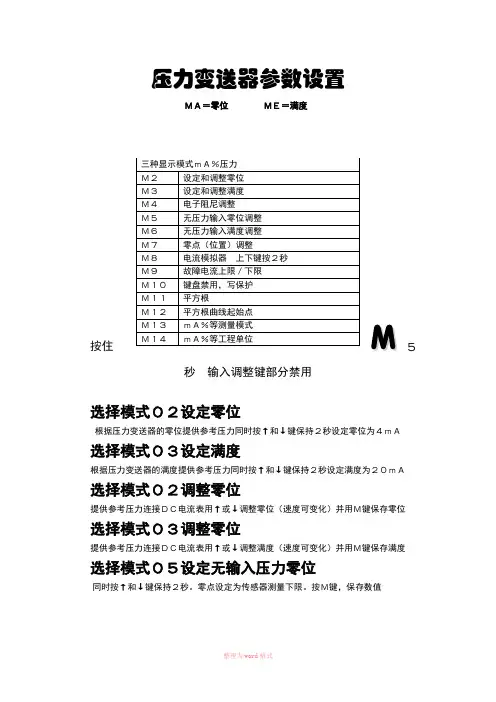
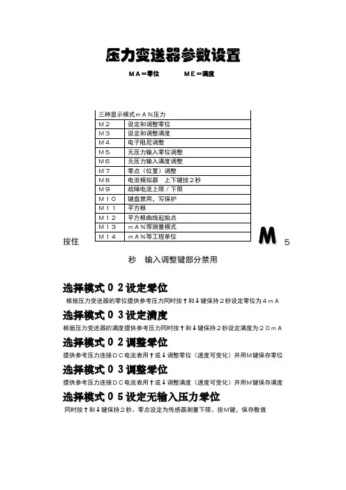
压力变送器参数设置
MA=零位ME=满度
5
秒输入调整键部分禁用
选择模式02设定零位
根据压力变送器的零位提供参考压力同时按↑和↓键保持2秒设定零位为4mA选择模式03设定满度
根据压力变送器的满度提供参考压力同时按↑和↓键保持2秒设定满度为20mA选择模式02调整零位
提供参考压力连接DC电流表用↑或↓调整零位(速度可变化)并用M键保存零位选择模式03调整零位
提供参考压力连接DC电流表用↑或↓调整满度(速度可变化)并用M键保存满度选择模式05设定无输入压力零位
同时按↑和↓键保持2秒。
零点设定为传感器测量下限。
按M键,保存数值
选择模式06设定无输入压力满度
同时按↑和↓键保持2秒。
满度设定为传感器测量上限。
按M键,保存数值选择模式05调整无输入压力零位
使用↑和↓键(速度可变化)调整零点压力设定值按M键,保存数值
选择模式06调整无输入压力满度
使用↑和↓键(速度可变化)调整满度压力设定值按M键,保存数值
零位(位置)调整:选择模式07
排空压力变送器或者抽真空(绝压表<0.01%满度)使用↑或↓设定零位使用↑或↓调整零位按M键,保存数值
选择模式M8电流模拟器上下键按2秒
选择模式M9故障电流上限/下限
选择模式M10键盘禁用,写保护
选择模式M11平方根△P
选择模式M12平方根曲线起始点△P
选择模式M13mA%等测量模式
选择模式M14mA%等工程单位
友情提示:本资料代表个人观点,如有帮助请下载,谢谢您的浏览!。

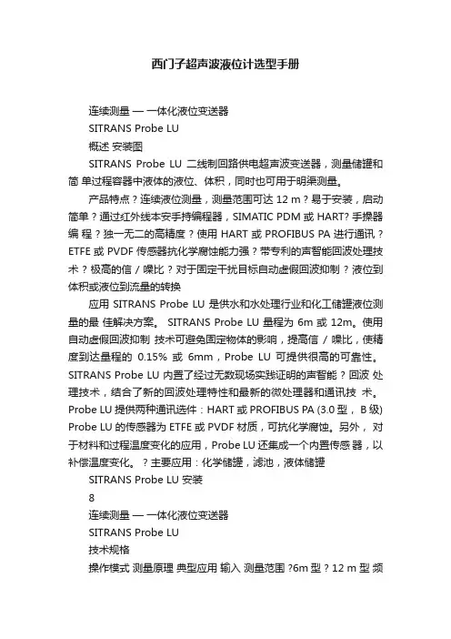
西门子超声波液位计选型手册连续测量—一体化液位变送器SITRANS Probe LU概述安装图SITRANS Probe LU 二线制回路供电超声波变送器,测量储罐和简单过程容器中液体的液位、体积,同时也可用于明渠测量。
产品特点 ? 连续液位测量,测量范围可达 12 m ? 易于安装,启动简单 ? 通过红外线本安手持编程器,SIMATIC PDM 或 HART? 手操器编程 ? 独一无二的高精度 ? 使用 HART 或 PROFIBUS PA 进行通讯 ? ETFE 或 PVDF 传感器抗化学腐蚀能力强 ? 带专利的声智能回波处理技术 ? 极高的信 / 噪比 ? 对于固定干扰目标自动虚假回波抑制 ? 液位到体积或液位到流量的转换应用 SITRANS Probe LU 是供水和水处理行业和化工储罐液位测量的最佳解决方案。
SITRANS Probe LU 量程为 6m 或 12m。
使用自动虚假回波抑制技术可避免固定物体的影响,提高信/ 噪比,使精度到达量程的0.15% 或6mm,Probe LU 可提供很高的可靠性。
SITRANS Probe LU 内置了经过无数现场实践证明的声智能 ? 回波处理技术,结合了新的回波处理特性和最新的微处理器和通讯技术。
Probe LU 提供两种通讯选件:HART 或 PROFIBUS PA (3.0 型, B级) Probe LU 的传感器为 ETFE 或 PVDF 材质,可抗化学腐蚀。
另外,对于材料和过程温度变化的应用,Probe LU 还集成一个内置传感器,以补偿温度变化。
? 主要应用:化学储罐,滤池,液体储罐SITRANS Probe LU 安装8连续测量—一体化液位变送器SITRANS Probe LU技术规格操作模式测量原理典型应用输入测量范围 ?6m型 ? 12 m 型频率输出 mA/HART ? 范围 ? 精度 PROFIBUS PA 性能分辨率精度重复性盲区刷新时间 ? 4/20 mA/HART 型 ? PROFIBUS 型温度补偿波束角额定工作条件环境条件 ? 地点 ? 环境温度 ? 相对湿度 / 入口保护 ? 安装等级 ? 污染等级介质条件 ? 法兰或螺纹处温度 ? 压力(容器)设计外壳材质防护等级重量电缆入口传感器材质 PBT(聚对苯二甲酸丁二醇酯) Type 4X/NEMA 4X, Type 6/NEMA 6/IP67/IP68 外壳2.1 kg 2 x M20 x 1.5 电线接头或 2 x?" NPT 螺纹 ETFE 或 PVDF -40 ~ 85 °C 0.5 bar 环境温度界面供电室内 / 室外 -40 ~ 80 °C 适于室外 I 4 编程本安西门子红外手操器 ? 用于红外手操器的认证红外手操器本安型 ATEX EEx ia IIC T4 CSA/FM Class I, Div. 1, Groups A, B, C, D -20 ~ 40 °C 专用红外脉冲信号 3V 锂电池(不可更换) ? 非易燃(美国)≤ 3 mm 量程的±0.15% 或 6mm,取其较大值≤ 3 mm 0.25 m ≤ 5s ≤ 5s,4mA ≤ 4s,15 mA 电流回路内置10° 危险区 ? 本安(欧洲)? 本安(美国/ 加拿大) ATEX II 1G EEx ia IIC T4 FM/CSA(需安全栅) T4, I 类, 1 区,A,B,C,D,组; II 类,E, F, G,组; III 类; FM ( 无需安全栅 ) T5:I 类,2 区, A, B,C 和 D 组认证通用型船用(只应用于 HART 通讯选件) CSAUS/C,FM, CE ? 英国劳氏船用认证 ? ABS 形式认证 PROFIBUS PA 4 ~ 20 mA ± 0.02 mA 型式 3,B 级电源 4 ~ 20 mA/HART 额定 24 V DC,最大 550 ? 负载;最大 30 V DC 4 ~ 20 mA 12,13,15 或 20 mA 取决于组态(一般用途或本安型)符合标准IEC 61158-2 存储器0.25 ~ 6m 0.25 ~ 12m 54 KHz 显示和控制接口组态本地:LCD 带棒状图远程:通过 HART 或 Pro?bus PA 使用西门子 SIMATIC PDM 软件(PC 机)或 HART 手操器或西门子红外线手操器 EEPROM 可在断电时保持信息,无需备用电池超声波液位测量测量储罐和简单过程容器的液位过程连接螺纹连接法兰连接其它连接2" NPT,2" BSPT,2" G 3" 通用法兰 FMS200 安装套件(见 53 页 ) 或用户提供的安装套件9连续测量—一体化液位变送器SITRANS Probe LU选型和订货数据订货号选型和订货数据其它设计请在订货号上加“-Z”并规定订货代码不锈钢标牌测量点数 / 识别 ( 最多 16 个字符 ) : HART/mA 设备使用手册英文版注意:该手册需单独订货。
西门子变频器选型手册升瑞电气是河南西门子变频器总代理,西门子变频器库存量大,欢迎新老用户来电咨询西门子变频器价格,另公司设有郑州西门子变频器维修中心。
公司将为每一个客户提供最低价位的西门子变频器及良好免费的西门子变频器售后服务。
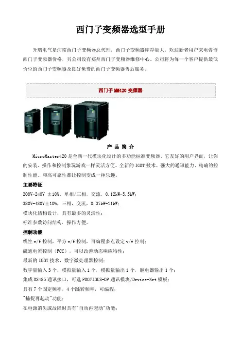
产品简介MicroMaster420是全新一代模块化设计的多功能标准变频器。
它友好的用户界面,让你的安装、操作和控制象玩游戏一样灵活方便。
全新的IGBT技术、强大的通讯能力、精确的控制性能、和高可靠性都让控制变成一种乐趣。
主要特征200V-240V ±10%,单相/三相,交流,0.12kW-5.5kW;380V-480V±10%,三相,交流,0.37kW-11kW;模块化结构设计,具有最多的灵活性;标准参数访问结构,操作方便。
控制功能线性v/f控制,平方v/f控制,可编程多点设定v/f控制;磁通电流控制(FCC),可以改善动态响应特性;最新的IGBT技术,数字微处理器控制;数字量输入3个,模拟量输入1个,模拟量输出1个,继电器输出1个;集成RS485通讯接口,可选PROFIBUS-DP通讯模块/Device-Net模板;具有7个固定频率,4个跳转频率,可编程;"捕捉再起动"功能;在电源消失或故障时具有"自动再起动"功能;灵活的斜坡函数发生器,带有起始段和结束段的平滑特性;快速电流限制(FCL),防止运行中不应有的跳闸;有直流制动和复合制动方式提高制动性能;采用BiCo技术,实现I/O端口自由连接。
保护功能过载能力为150%额定负载电流,持续时间60秒;过电压、欠电压保护;变频器过温保护;接地故障保护,短路保护;I2t电动机过热保护;采用PTC通过数字端接入的电机过热保护;采用PIN编号实现参数连锁;闭锁电机保护,防止失速保护。
产品简介MicroMaster430是全新一代标准变频器中的风机和泵类变转矩负载专家。
功率范围7.5kW至250kW。


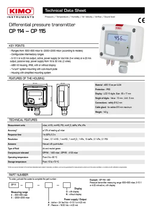
Differential pressure transmitterCP 114 – CP 115KEY POINTSMaterial : ABS V0 as per UL94Protection : IP65Display : LCD 10 digits. Size : 50 x 17 mmHeight of digits : Value : 10 mm ; Unit : 5 mm Connections : safety Ø 6.2 mmCable gland : for cables Ø 8 mm maximum Weight : 143 g- Ranges from -500/+500 mbar to -2000/+2000 mbar (according to models)- Configurable intermediary ranges- 0-10 V or 4-20 mA output, active, power supply 24 Vac/Vdc (3-4 wires) or 4-20 mA output, passive loop, power supply from 16 to 30 Vdc (2 wires)- ABS V0 housing, IP65, with or without display - “¼ turn” system mounting with wall-mount plate - Housing with simplified mounting systemFEA TURES OF THE HOUSING90 mm109 m m46 mmTECHNICAL FEA TURESMeasurement units mbar, inWG, mmHG, PSI, mmH 2O, daPa, hPa, kPa Accuracy*±1.5% of reading ±3 mbar Response time 1/e (63%) 0.3 sResolution 1 mbar ; 0.1 inWG ; 1 mmHG ; 1 mmH 2O ; 1 hPa ; 10 daPa ; 0.1 kPa ; 0.1 PSI Autozero Manual with push-button Type of fluidAir and neutral gasesOverpressure tolerated CP114 : 1400 mbar ; CP115 : 4100 mbar Operating temperature From 0 to +50 °C Storage temperatureFrom -10 to +70 °CMeasuring range4 : -500/+500 mabr5 : -2000/+2000 mbarPART NUMBERCP 11To order, just add the codes to complete the part number :Power supply / OutputA : Active – 24 Vac/Vdc – 0-10 V or 4-20 mA P : Passive – 16/30 Vdc – 4-20 mADisplayO : with display N : without displayExample : CP 114 – AOPressure transmitter measuring range -500/+500 mbar, 0-10 V or 4-20 mA active, with display*All the accuracies indicated in this technical datasheet were stated in laboratory conditions, and can be guaranteed for measurements carried out in the same conditions, or carried out with calibration compensation.TECHNICAL SPECIFICA TIONSCONNECTIQUESPressure connectionsOutput / Supply- active sensor 0-10 V or 4-20 mA (alim. 24 Vac/Vdc ± 10%), 3-4 wires - passive loop 4-20 mA (power supply 16/30 Vdc), 2 wires - maximum load : 500 Ohms (4-20 mA)- minimum load : 1 K Ohms (0-10 V)Consumption2 VA (0-10 V) or max. 22 mA (4-20 mA)Electromagnetical compatibility EN61326Electrical connection Screw terminal block for cables Ø0.05 to 2.5 mm 2 Communication to PC Kimo USB-mini Din cable EnvironmentAir and neutral gasesInside the front housingDIP SwitchsOutput terminalblockPower supply terminalblockLCC-S connectionFixed back housingRemovable front faceCable glandAutozeroELECTRICAL CONNECTIONS – as per NFC15-100 standardThis connection must be made by a qualified technician . To make the connection, the transmitter must not be energized.For CP114/115 – AO models and CP114/115 – ANmodels with 0-10 V or 4-20 mA output – active, 4 wires:A-+0-10 V output76LN Power supply 24 Vac class IIor N L12+3VP +5IP4GND -7+6-Power supply 24 Vdc-VRegulator display orPLC/BMS passive typeor-+4 wiresTo make a 3-wire connection, before powering up the transmitter, please connect the output ground to the input ground. See drawing below.4 wires3 wires+4-20 mA outputRegulator display orPLC/BMS active type-12+3VP +5IP4GND -7+6-3 wiresPower supply24 Vdc+5IP4GND -7L 6N +Power supply24 Vac class IILN A-+0-10 V outputor VRegulator display or PLC/BMS passive type-+Sortie 4-20 mARegulator display or PLC/BMSactive type orSETTINGS AND USE OF THE TRANSMITTERTo perform an autozero, unplug the 2 pressure connections tubes and press the “Autozero” key.When an autozero has been performed, “On” green light turns off then turns on, and on transmitters equipped with a display, “autoZ” is displayed.➢ Autozero➢ ConfigurationTo configure the transmitter, it must not be energized. Then, you can make the settings required, with the DIP switches (as shown on thedrawing below). When the transmitter is configured, you can power it up.To configure the transmitter, unscrew the 4screws from the housing then open it. DIPswitches allowing the different settings arethen accessible.To set a measuring range, put the 1, 2 and 3 on-off switches as indicated in the table below.➢ Measuring range settings – left DIP switchExample :● From 0 to 750 mmH2O, measuring range is 750 mmH2O.● From -500 mbar to +500 mbar, measuring range is 1000 mbar.● Measuring ranges of the CP114transmitter on the ±500 mbar range according to the measurement unit.● Measuring ranges of the CP115transmitter on the ±2000 mbar range according to the measurement unit.Type oftransmitterCP114CP115CP114CP115CP114CP115CP114CP115CP114CP115 mbar100500200750300100040015005002000inWG40.0200.080.0300.0120.0400.0160.0600.0200.00800.0 kPa10.050.020.075.030.0100.040.0150.050.0200.0 PSI 2.010.0 4.015.0 6.020.08.030.010.040.0 mmHg8040016060024080032012004001600mmH2O1000500020007500300010 000400015 000500020000 daPa 1.0 5.0 2.07.5 3.010.0 4.015.0 5.020.0 hPa100500200750300100040015005002000 12341234123412341234Combination 1Combination 2Combination 3Combination 4Combination 5Measuringranges settingStandard range orcentral 0 settingLeft DIP switch12341234Right DIP switchOutput settingUnits settingOn-off switch➢ Standard range / central zero setting – left DIP switchTo set the type of measuring range, put the on-off switch 4 as indicated beside :Configurations Full scale Central zeroCombinationsExample 0-100 mbar : Full scale / 0Central zero(0 / 100 mbar)(-50 mbar / 0 / +50 mbar)For CP114/115 – PO models and CP114/115 – PN models with 4-20 mA output – passive :2 wires IT57+6-Power supply16-30 VdcVdcA-+IT57+6-Vdc-2 wires+A2 wires............Display/regulator/PLCpassive typeDisplay/regulator/PLCactive type +-16-30 VdcorF T a n g – t r a n s m i t t e r _C P 114-115 – 08/03/13 – R C S (24) P ér i g u e u x 349 282 095 N o n -c o n t r a c t u a l d o c u m e n t – W e r e s e r v e t h e r i g h t t o m o d i f y t h e c h a r a c t e r i s t i c s o f o u r p r o d u c t s w i t h o u t p r i o r n o t i c e .MAINTENANCEPlease avoid any aggressive solvent. Please protect the transmitter and its probes from any cleaning product containing formalin, that may be used for cleaning rooms or ducts.OPTIONS AND ACCESSORIES●KIAL-100A : Power supply class 2 , 230 Vac input, 24 Vac output●LCC-S : configuration software with USB cable●Connection tube ●Connection fittings ●Through-connections●Straight connections ●Spherical coupling nut➢Output setting – right DIP switch (CP114/115 – AO and CP114/115 – AN models)To set the type of analogue output, please put the on-off switch of the output as shown beside.➢Units setting – right DIP switchTo set a measurement unit, put the on-off switches 2, 3 and 4 of the units as shown in the table below.Please follow carefully the combinations beside with the DIP switch. If the combination is wrongly done, the following message will appear on the display of the transmitter “CONF ERROR”. In that case, you will have to unplug the transmitter, place the DIP switches correctly, and then power the transmitter up.ConfigurationsmbarinWGkPaPSImmHGmmH 2OdaPahPaCombinationsConfigurations4-20 mA0-10 VCombinations1234123412341234123412341234123412341234MOUNTINGTo mount the transmitter, mount the ABS plate on the wall (drilling : Ø6 mm, screws and pins are supplied).Insert the transmitter on the fixing plate (see A on the drawing beside). Rotate the housing in clockwise direction until you hear a “click” which confirms that the transmitter is correctly installed.Once the transmitter is installed and powered up, please make an autozero to guarantee the correct working of the transmitter in any position.An easy and friendly configuration with the software !You can configure your own intermediary ranges.Caution : the minimum difference between the high range and the low range is 20.For example, it is possible to set the instrument from -20 to 0 mbar, from 0 to +20 mbar, or from -10 to +10 mbar...• To access the configuration via software :- Set the DIP switches as shown beside. Nota : the on-off switch 1 of the right DIP switch can be inany position (selection of the analogue output 0-10 V or 4-20 mA)- Connect the cable of the LCC-S to the connection of the transmitter.• Please refer to the user manual of the LCC 100 to make the configuration.CONFIGURA TION VIA LCC-S SOFTW ARE (option)1234Left DIP switch 1234Right DIP switchThe configuration of the parameters can be done either with the DIP switch or via software (you can not combine both solutions).7.5mm8mm4.5mm40mm50m m68m m75mm37.5mm23.75m m14mmAA。
压力变送器参数设置
MA=零位ME=满度
5
秒输入调整键部分禁用
选择模式02设定零位
根据压力变送器的零位提供参考压力同时按↑和↓键保持2秒设定零位为4mA选择模式03设定满度
根据压力变送器的满度提供参考压力同时按↑和↓键保持2秒设定满度为20mA选择模式02调整零位
提供参考压力连接DC电流表用↑或↓调整零位(速度可变化)并用M键保存零位选择模式03调整零位
提供参考压力连接DC电流表用↑或↓调整满度(速度可变化)并用M键保存满度选择模式05设定无输入压力零位
同时按↑和↓键保持2秒。
零点设定为传感器测量下限。
按M键,保存数值
选择模式06设定无输入压力满度
同时按↑和↓键保持2秒。
满度设定为传感器测量上限。
按M键,保存数值选择模式05调整无输入压力零位
使用↑和↓键(速度可变化)调整零点压力设定值按M键,保存数值选择模式06调整无输入压力满度
使用↑和↓键(速度可变化)调整满度压力设定值按M键,保存数值零位(位置)调整:选择模式07
排空压力变送器或者抽真空(绝压表<0.01%满度)使用↑或↓设定零位使用↑或↓调整零位按M键,保存数值
选择模式M8电流模拟器上下键按2秒
选择模式M9故障电流上限/下限
选择模式M10键盘禁用,写保护
选择模式M11平方根△P
选择模式M12平方根曲线起始点△P
选择模式M13mA%等测量模式
选择模式M14mA%等工程单位。

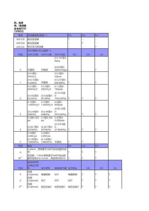
西门子变送器选型说明压力变送器(Hart )7MF4033-1AA10-2AC0-ZA02+Y01+Y15{Y01: }{Y15: }SITRANS P DS III ,HART, 4-20 MA 用于测量压力1 测量元件冲液:硅油测量元件清洗:标准A 量程: 0.83 (25)kPa (0.12 ... 3.6psi), 最大允许测量压力 4 BARB 量程:0,01 ... 1bar g (0.15 ...14.5psi),最大允许测量压力4barC 量程:0,04 ... 4 BARG(0.58 ... 58PSI G),最大允许测量压力 10BARD 量程:0,16 ... 16 barg(2.32 ... 232psi g),最大允许测量压力 32barE 量程:0,63 ... 63 barg(9.14 ... 914psi g),最大允许测量压力100 barF 量程:1,6 ...160 barg(23.2 ... 2320psi g),最大允许测量压力250 barG量程:4,0 ...400 barg(58.0 ... 5802psi g),最大允许测量压力600 barA 密封膜片不锈钢过程连接不锈钢1 过程连接: 阴螺纹1/2-14 NPT0 铸铝外壳2 默认英文名牌A 无防爆UnrestrictedC 电气连接/电缆入口: CABLE GLAND1/2-14 NPT0 无液晶数字显示A02不锈钢支架Y0 1 量程 (直行程特征 ) 文字说明:Y01:...TO ...MBAR,KPA,MP A,...Y1 5 不锈钢铭牌 (测量点描述) 最多16个字符, 文本说明绝压变送器(Hart )7MF4233-1FA10-2AC0-ZA02+Y01+Y15{Y01: }{Y15: }SITRANS P DS III ,HART, 4-20 MA 用于测量绝压1 测量元件冲液:硅油测量元件清洗:标准F 量程 : 43 TO 1300MBAR A (0.62 TO18.9 PSI A), 最大允许测量压力10BARH 量程 :30 bara (435psia), 最大允许测量压Unrestricted力 100bar A 密封膜片不锈钢过程连接不锈钢1 过程连接: 阴螺纹1/2-14 NPT0 铸铝外壳2 默认英文名牌A 无防爆C 电气连接/电缆入口: CABLE GLAND1/2-14 NPT0 无液晶数字显示A02不锈钢支架Y0 1 量程 (直行程特征 ) 文字说明:Y01:...TO ...MBAR,KPA,MP A,...Y1 5 不锈钢铭牌 (测量点描述) 最多16个字符, 文本说明差压变送器(Hart 7MF4433-1BA22-2AC0-ZA02+A40+Y01+Y15{Y01: }1 SITRANS P DS III,HART, 4-20 MA 用于测量差压和流量,Unrestricted){Y15: } PN 32/1601 测量元件冲液:硅油测量元件清洗:标准B 量程: PN 32 (MWP464 PSI): 20 MBAR(8.03 INH2O), 最大静压32 BAR C 量程:PN 160(MWP2320psi):60mbar(24.09inH2O), 最大静压160barD 量程:PN 160(MWP2320psi):250mbar(100.4inH2O),最大静压160barE 量程:PN 160(MWP2320psi):600mbar(240.9inH2O),最大静压160barG 量程:PN 160(MWP2320psi): 5bar(2008inH2O),最大静压 160barH 量程:PN 160(MWP2320psi):30 bar(435psi),最大静压160barA 密封膜片不锈钢过程连接不锈钢2 过程连接: : 1/4-18NPT 安装螺钉7/16-20 UNF2 铸铝外壳;过程法兰螺钉:不锈钢2 默认英文名牌A 无防爆C 电气连接/电缆入Unrestricted口: 1/2-14 NPT 0 无液晶数字显示表头A02不锈钢支架A4 0 排汽排液阀(1/4-18 NPT) WITH VALVE IN MATERIAL OF PROCESS FLANGEY0 1 量程 (直行程特征 ) 文字说明:, Y01:...TO ...MBAR,KPA,MP A,...Y1 5 不锈钢铭牌 (测量点描述) 最多16个字符, 文本说明差压变送器(Hart )7MF4533-1BA22-2AC0-ZA02+A40+Y01+Y15{Y01: }{Y15: }1 SITRANS P DS III,HART, 4-20 MA 用于测量差压和流量,PN 4201 测量元件冲液:硅油测量元件清洗:标准B 量程: PN 32 (MWP464 PSI): 20 MBAR(8.03 INH2O), 最C 量程:PN 160(MWPD 量程:PN 160(MWPE 量程:PN 160(MWPG 量程:PN 160(MWPH 量程:PN 160(MWPUnrestricted大静压32 BAR 2320psi):60mbar(24.09inH2O), 最大静压160bar 2320psi):250mbar(100.4inH2O),最大静压160bar2320psi):600mbar(240.9inH2O),最大静压160bar2320psi): 5bar(2008inH2O),最大静压 160bar2320psi):30 bar(435psi),最大静压160barA 密封膜片不锈钢过程连接不锈钢2 过程连接: : 1/4-18NPT 安装螺钉7/16-20 UNF2 铸铝外壳;过程法兰螺钉:不锈钢2 默认英文名牌A 无防爆C 电气连接/电缆入口: 1/2-14 NPT0 无液晶数字显示表头A02不锈钢支架UnrestrictedA4 0 排汽排液阀(1/4-18 NPT) WITH VALVE IN MATERIAL OF PROCESS FLANGEY0 1 量程 (直行程特征 ) 文字说明:, Y01:...TO ...MBAR,KPA,MP A,...Y1 5 不锈钢铭牌 (测量点描述) 最多16个字符, 文本说明UnrestrictedUnrestricted。
西门子选型手册1 6ES7 212-1AB23-0XB0 CPU(8I/6O)晶体管输出2 6ES7 212-1BB23-0XB0 CPU (8I/6O)继电器输出3 6ES7 212-1AB23-0XB8 CPU(8I/6O)晶体管输出 CN4 6ES7 212-1BB23-0XB8 CPU (8I/6O)继电器输出 CN5 6ES7 214-1AD23-0XB0 CPU(14I/10O)晶体管输出6 6ES7 214-1AD23-0XB8 CPU(14I/10O)晶体管输出 CN7 6ES7 214-1BD23-0XB0 CPU(14I/10O)继电器输出8 6ES7 214-1BD23-0XB8 CPU(14I/10O)继电器输出 CN9 6ES7 214-2AD23-0XB0 CPU224XP(14DI/10DO,2AI,1AO)晶体管输出10 6ES7 214-2BD23-0XB0 CPU224XP (14DI/10DO,2AI,1AO)继电器输出11 6ES7 214-2AD23-0XB8 CPU224XP (14DI/10DO,2AI,1AO)晶体管输出12 6ES7 214-2BD23-0XB8 CPU224XP (14DI/10DO,2AI,1AO)继电器输出13 6ES7 216-2AD23-0XB0 CPU ( 24I/16O ) 晶体管输出14 6ES7 216-2BD23-0XB0 CPU(24I/16O)继电器输出15 6ES7 216-2AD23-0XB8 CPU ( 24I/16O ) 晶体管输出 CN16 6ES7 216-2BD23-0XB8 CPU(24I/16O)继电器输出 CN17 6ES7 221-1BF22-0XA0 8点24VDC输入18 6ES7 221-1BF22-0XA8 8点24VDC输入 CN19 6ES7 221-1BH22-0XA0 16点24VDC输入20 6ES7 221-1BH22-0XA8 16点24VDC输入 CN21 6ES7 222-1HF22-0XA0 8点继电器输出22 6ES7 222-1HF22-0XA8 8点继电器输出 CN23 6ES7 222-1BF22-0XA0 8点24VDC输出24 6ES7 222-1BF22-0XA8 8点24VDC输出 CN25 6ES7 223-1PH22-0XA0 8入8出模块继电器输出26 6ES7 223-1PH22-0XA8 8入8出模块继电器输出 CN27 6ES7 223-1PL22-0XA0 16入16出模块继电器输出28 6ES7 223-1PL22-0XA8 16入16出模块继电器输出 CN29 6ES7 223-1HF22-0XA0 4入4出模块继电器输出30 6ES7 223-1HF22-0XA8 4入4出模块继电器输出 CN31 6ES7 223-1BF22-0XA0 4入4出24VDC32 6ES7 223-1BF22-0XA8 4入4出24VDC CN33 6ES7 223-1BH22-0XA0 8入8出24VDC34 6ES7 223-1BH22-0XA8 8入8出24VDC CN35 6ES7 223-1BL22-0XA0 16入16出24VDC36 6ES7 223-1BL22-0XA8 16入16出24VDC CN37 6ES7 231-0HC22-0XA0 4入模拟量模块38 6ES7 231-0HC22-0XA8 4入模拟量模块 CN39 6ES7 235-0KD22-0XA0 4入1出模拟量模块40 6ES7 235-0KD22-0XA8 4入1出模拟量模块 CN41 6ES7 232-0HB22-0XA0 2出模拟量模块42 6ES7 232-0HB22-0XA8 2出模拟量模块 CN43 6ES7 277-0AA22-0XA0 PROFIBUS-DP模块44 6ES7 272-0AA30-0YA0 TD 200显示设定单元45 6ES7 901-3CB30-0XA0 计算机编程电缆及软件46 6ES7 291-8GF23-0XA0 EEPROM 64K47 6ES7 291-8BA20-0XA0 电池48 6ES7 290-6AA20-0XA0 扩展转接电缆 0.8米49 6ES7 231-7PD22-0XA0 4路热电耦模块50 6ES7 231-7PD22-0XA8 4路热电耦模块 CN51 6ES7 231-7PB22-0XA0 2路热电阻模块52 6ES7 231-7PB22-0XA8 2路热电阻模块 CN53 6GK7243-1EX00-0XE0 以太网通讯卡西门子可编程SIEMENS S7-300系列序号型号描述1 6ES7 312-1AE13-0AB0 CPU312,16KRAM, MAX 256DI/O,64AI/O,MMC2 6ES7 312-5BE03-0AB0 CPU312C,32KRAM, 本机10I/6O,256DI/O,64AI/O,40PIN3 6ES7 313-5BF03-0AB0CPU313C,64KRAM,MAX 1016DI/O,253AI/O,2个40PIN<, /P>4 6ES7 313-6CF03-0AB0 CPU313C-2DP,64KRAM,MAX 8192DI/O,512AI/O,40PIN5 6ES7 314-1AG13-0AB0 CPU314,48KRAM,MAX1024DI/O,256AI/O,MMC6 6ES7 314-6BG03-0AB0 CPU314, 96KRAM,MAX1024DI/O,256AI/O,MMC9 6ES7 314-6CG03-0AB06ES7 315-2AG10-0AB06ES7 307-1BA00-0AA0CPU314C-2DP,96KRAM,MAX8192DI/O,512AI/O,2个40PINCPU315-2DP,128KRAM,MAX16384DI/O,1024AI/O,MMCS7-300电源DC24V,2A10 6ES7 307-1EA00-0AA0 S7-300电源DC24V,5A11 6ES7 307-1KA01-0AA0 S7-300电源DC24V,10A12 6ES7 321-1BL00-0AA0 数字输入模块32点入,DC24V13 6ES7 321-1BH02-0AA0 数字输入模块16点入,DC24V14 6ES7 321-1FF01-0AA0 8点120V/230V AC 输入15 6ES7 322-1BL00-0AA0 数字输出模块32点出,DC24V,0.5A16 6ES7 322-1HF01-0AA0 数字输出模块8点继电器出,AC220V,2A17 6ES7 322-1BH01-0AA0 数字输出模块16点出,DC24V,0.5A18 6ES7 322-1HH01-0AA0 数字输出模块16点继电器输出2A19 6ES7 322-1FH00-0AA0 数字输出模块16点输出0.5A20 6ES7 323-1BH01-0AA0 数字输入/输出模块,8入/8出,DC24V,0.5A21 6ES7 323-1BL00-0AA0 数字输入/输出模块,16入/16出,DC24V,0.5A22 6ES7 331-7KF02-0AB0 模拟量输入模板,8通道,0~10V,4~20MA23 6ES7 331-7KB02-0AB0 模拟量输入模板,2通道24 6ES7 332-5HD01-0AB0 模拟量输出模板,4通道,0~10V,4~20mA25 6ES7 332-5HB01-0AB0 模拟量输出模板,2通道26 6ES7 340-1AH02-0AE0 点对点通讯模板,CP340-1A,带RS232C口27 6ES7 340-1AH01-7BA0 CP340软件手册28 6ES7 340-1CH02-0AE0 点对点通讯模板,CP340-1C,带RS485口29 6ES7 350-1AH03-0AE0 单通道计数模块(FM350-1)30 6ES7 350-1AH00-7BG0 FM350-1组态软件手册31 6ES7 350-2AH00-0AE0 8通道计数模块(FM350-2)37 6ES7953-8LF20-0AA06ES7953-8LG11-0AA06ES7953-8LJ20-0AA06ES7953-8LL20-0AA06ES7953-8LM20-0AA06ES7 971-1AA00-0AA0 MMC 64KMMC 128KMMC 512KMMC 2MMMC 4M后备电池,3.4V,1Ah(CPU313,314用)38 6ES7 392-1AJ00-0AA0 前连接器,20针39 6ES7 392-1AM00-0AA0 前连接器,40针40 6ES7 390-1AE80-0AA0 导轨,480mm41 6ES7 390-1AF30-0AA0 导轨,530mm42 6ES7 390-1AJ30-0AA0 导轨,830mm43 6ES7 360-3AA01-0AA0 中央模板接口模板44 6ES7 361-3CA01-0AA0 扩展模板接口模板45 6ES7 365-0BA01-0AA0 接口模板(一对),带1M电缆46 6ES7 368-3BB01-0AA0 接口模板连接电缆,1M47 6ES7 368-3BC51-0AA0 接口模板连接电缆,2.5M48 6ES7 972-0CB20-0XA0 PC MPI电缆49 6ES7 972-0BA41-0XA0 L2网接口不带编程口50 6ES7 972-0BB41-0XA0 L2网接口带编程口51 6ES7 972-0AA01-0XA0 RC485 L2/MPI中继器52 6GK1 561-1AA01 CP5611 PCI通讯卡53 6GK1 561-3AA01 CP5613 PCI通讯卡54 6GK7 342-5DA02-0XE0 CP342-5通讯模块55 6A V6642-0DA01-1AX0 OP177B 5.7寸用户内存2048K 分辨率320×240 25656 6A V6642-0DC01-1AX0 OP177B 5.7寸用户内存2048K 分辨率320×240 蓝色57 6A V6 642-0AA01-0AX0 TP177A 触摸屏 5.7寸分辨率320×240 蓝色替代TP170A58 6A V6 642-0BA01-1AX0 TP177B 触摸屏 256色替代TP170B59 6A V6 641-0DD01-1AX0MP277 替代TP270-10 10.4寸用户内存6M 分辨率640×480 按键60 6ES7 354-1AH01-0AE0 FM354 伺服电机定位模块61 6ES7 355-0VH10-0AE0 带4个模拟输出的四通道闭环控制模块 FM355C62 6ES7 355-1VH10-0AE0 用于4个步进或脉冲控制器的闭环控制模块FM355S西门子可编程SIEMENS S7-400系列序号型号描述1 6ES7400-1TA01-0AA0 底板2 6ES7400-1JA01-0AA0 底板3 6ES7412-2XJ05-0AA0 CPU4124 6ES7414-2XK05-0AB0 CPU4145 6ES7407-0KA01-0AA0 10A电源6 6ES7952-1KK00-0AA0 1M存储器7 6ES7952-1KL00-0AA0 2M存储器8 6ES7971-0BA00 后备电池9 6ES7421-1BL01-0AA0 32点数字输入,24VDC10 6ES7421-7BH01-0AB0 16点数字输出,24VDC11 6ES7422-1BL00-0AA0 32点数字输出,24VDC12 6ES7422-1BH11-0AA0 16点数字输出,24VDC13 6ES7422-1HH00-0AA0 16点继电器输出14 6ES7431-7QH00-0AB0 16点模拟量输入15 6ES7431-1KF00-0AB0 8点模拟量输入16 6ES7431-7KF00-0AB0 8点模拟量输入17 6ES7431-7KF10-0AB0 8点模拟量输出18 6ES7432-1HF00-0AB0 8点模拟量输出19 6ES7460-0AA01-0AB0 扩展模块20 6ES7461-0AA01-0AA0 扩展模块21 6ES7461-0AA00-7AA0 终端电阻22 6ES7468-1BB50-0AA0 扩展电缆23 6ES7492-1AL00-0AA0 接线端子。
SIMOVERTMASTERDRIVES矢量控制三相交流传动系统电压源型变频调速样本 DA 65.10 • 2006单电机和多电机传动0.55 kW 到2300 kW西门子电气传动有限公司对于6SE70书本型和装机装柜型装置提供电压等级为400V的产品,对6SE71变频调速柜提供电压等级为400V、500V、690V全功率范围的产品。
对增强书本型装置(Compact PLUS units),暂不在西门子电气传动有限公司供货范围内,如果您需要,请与当地西门子销售机构联系。
如果您需要其它电压等级和功率的产品以及多电机传动的直流母线方案,也请与当地的西门子销售机构联系。
注意:技术数据仅为一般信息。
关于产品的安装、操作和保养,请参见相应的操作手册。
所使用的产品标识是Siemens AG或其它企业的商标和产品名称。
商标® SIMADYN, SIMATIC, SIMOLINK, SIMOREG, SIMOVERT, SIMOVIS, SITOR, STEP, STRUC和USS是Siemens注册商标。
样本中提到的其它产品和系统名称为其拥有者的(注册)商标,处理时应遵守相应规定。
•样本中的外形尺寸单位为mm。
•西门子公司保留更改技术数据、订货号的权利。
1/2应用内容提要1/4装置和系统元件1/6电子板选件和软件选件订货号举例1/8增强书本型、书本型和装机装柜型装置1/8变频调速柜Vector Control概述1/2概述应用1工程型传动的最佳解决方案SIMOVERT MASTERDRIVES 矢量控制的变频器是具有IGBT 逆变器、全数字技术的有电压中间回路的变频器。
它同西门子三相交流电动机一起为所有工业领域和所有应用场合提供高性能、最经济的解决方案。
SIMOVERT MASTERDRIVES 基于系统的传动技术,一种通用和模块式的标准系列装置SIMOVERT MASTERDRIVES 矢量控制系列变频器是全系列通用和模块化的产品:•标准装置功率范围从0.55kW ~2300kW 。
免费下载SIEMENS压力变送器选型规则今天我们给大家带来的是SIEMENS压力变送器选型规则,希望我们的资料下载能帮助您选到您最想要的SIEMENS压力变送器。
1、西门子变送器要测量什么样的压力:先确定系统中要确认测量压力的最大值,一般而言,需要选择一个具有比最大值还要大1.5倍左右的压力量程的西门子变送器。
这主要是在很多系统,特别是水压测量和加工处理中,有峰值和持续不规则的上下波动,这种瞬间的峰值能破坏压力传感器,然而,由于这样做会精度下降。
于是,可以用一个缓冲器来降低压力毛刺,但这样会降低传感器的响应速度。
所以在选择西门子变送器时,要充分考虑压力范围,精度与其稳定性。
2、什么样的压力介质:要考虑的是压力西门子变送器所测量的介质,黏性液体、泥浆会堵上压力接口,溶剂或有腐蚀性的物质会不会破坏西门子变送器中与这些介质直接接触的材料。
一般的压力西门子变送器的接触介质部分的材质采用的是316不锈钢,如果介质对316不锈钢没有腐蚀性,那么基本上所有的压力西门子变送器都适合对介质压力的测量;如果介质对316不锈钢有腐蚀性,那么就要采用化学密封,这样不但起到可以测量介质的压力,也可以有效的阻止介质与压力西门子变送器的接液部分的接触,从而起到保护压力西门子变送器,延长了压力西门子变送器的寿命.3、西门子变送器需要多大的精度:决定精度的有:非线性、迟滞性、非重复性、温度、零点偏置刻度、温度的影响,精度越高,价格也就越高。
每一种电子式的测量计都会有精度误差,但是由于各个国家所标的精度等级是不一样的。
4、西门子变送器的温度范围:通常一个西门子变送器会标定两个温度范围,即正常操作的温度范围和温度可补偿的范围。
正常操作温度范围是指西门子变送器在工作状态下不被破坏的时候的温度范围,在超出温度补范围时,可能会达不到其应用的性能指标。
温度补偿范围是一个比操作温度范围小的典型范围。
在这个范围内工作,西门子变送器肯定会达到其应有的性能指标。
P RESSURE T RANSMITTER PASCAL CV T YPE S ERIES FOR FOOD /PHARMACEUTICALS /CV 3110BIOTECHNOLOGYSignal output::● 4..20 mA, can be retrofitted with optional HART ®protocol ●PROFIBUS PA ■Function modules●Multifunctional display with 5-segment digital display and bar graph●HART ®protocol●Switching module with 2 floating channels, maximum 1.5 Aswitching current, electrically isolated at all sides, without additional auxiliary power ■Function module replacement on site without recalibration "plug and measure"■Watchdog for electronics modules and measuring cell■Hygienic design according to EHEDG, FDA und GMP recommendations ■Material and surface quality according to the hygienic requirements ■Limits of measuring range 0...80 mbar to 0...40 bar ■Accuracy: < 0.25% (linearity, hysteresis and repeatability)■Turndown 5:1■Explosion protection: II 1/2G EEx ia IIC T6■Medium temperature up to 160 °C■Piezoresistive measuring cell, directly aerated, fully weldedThe pressure transmitter PASCAL CV is suited for measuring the relative and absolute pressures of gases, vapors and liquids. The type series CV3110 has been developed to meet the stringent demands of food processing, pharmaceutical technology, and biotechnology. Special attention has been given to good surface quality. Thus, for instance, roughness values to Ra 0.4 µm can be guaranteed for wetted parts (for welds: Ra < 0.8µm) or the system can be electropolished as well.The modular design of the pressure transmitter allows users to choose the best possible device for his specific operating requirements.PASCAL CV is equipped with a variety of process connections and uses smart module technology for display, switching and communication purposes.These functional modules can be exchanged or extended with ease without having to remove the transmitter from the process.Other designs available●PASCAL CV 3100 for general application●PASCAL CV 3120 for chemical/petrochemical industryProcess connection: all standard screw-in, flange and inline connectionsBasic modulePROFIBUSFunction modulesDisplay moduleHART ®-moduleSwitchingmodule4...20 mAData Sheet: D4-017/2P. 1Rev. 0D3Housing hygienic housing design with screw cap and windowMaterialhousing:stainless steel mat.no. 1.4301window:Macrolon gasket:NBR O-ringConstructiontwo-chamber system, minimum housing volume, excellent moisture and condensate protection Pressure compensation PTFE filter system Degree of protection EN 60529, IP 66Climatic category DIN EN 60721 3-4, 4K4HElectrical connection· screwed terminals 1 mm², cable entry fitting through screwing· circular plug connector M 12Weightstandard device without diaphragm seal and function modules approx. 0.65 kgHousing designConstruction welded designDiaphragm modifications see page 5 or order code Materialstainless steel mat.-no. 1.4404 or 1.4435see order codeSensor piezoresistive measuring element System fillfoodstuff oil FD1 (USDA-H1)according to FDAAmbient temperature -20 to 85°C Process temperature depending on design Allowed storage temperature -40...85 °CNote safety values as per examination certificate!Standard design 12....40 VDC Ex-proof design12....30 VDCInterference emission EN 50081 section 1Noise immunityEN 50082 section 2EU examination certificateII 1/2G EEx ia IIC T6Data Sheet: D4-017/2Housing design Measuring system Signal4...20 mA, two-wire,optional with HART protocol (not yet available)Current range 3.8 - 20.8 mA Current limitation approx. 22 mA Alarm state < 3.6 mA, optional > 21 mA Delay time approx. 160 ms measuring cycle 6 measurements / second Measuring range setting turndown 5:1Damping t 0.0 - 120.0 secondsLoadR <(Ohm)Limit point setting DIN 16086Reference conditions DIN EN 60770-1Calibration position vertical mounting position Linearity errors< 0.15% of span TD 5:1 no changeHysteresis < 0.05% of nominal range Repeatability < 0.05% of nominal range Influence of mounting position < 3.5 mbar Long-term drift < 0.1%/year of nominal range DIN EN 60770-1Temperature effecta)Lower range value / upper range value in range 0...60°C ± 0.15%/10 K of nominal range in range < 0°C, > 60°C ± 0.2%/10 K of nominal range b) process connection (diaphragm seal) depending on design flat diaphragm zero point error DN 25/1"4,8 mbar/10 K DN 32/1 1/2"2,3 mbar/10 K DN 401,6 mbar/10 K DN 50/2"0,6 mbar/10 K inline diaphragm zero point error DN 25/1"9,5 mbar/10 K DN 32/1 1/2"4,1 mbar/10 K DN 403,9 mbar/10 K DN 50/2"3,9 mbar/10 KThe specified zero error for the process connection is a guide value for a standard design. We can provide a detailed system calculation upon request. Systems with reduced diaphragm seal errors are also available.Temperature ranges OutputAccuracyApproval/testsP 0 t 2xt 3xt 4xt 5xte.g. damping t = 10 s = 50 s ~100 %windowsO-ring-seal electronicsfully encapsulated replaceablegasketsensor chamber fully encapsulated (reduced volume)plug connection cable entry fitting U - 12 V 22.5 mA^Process connection separate terminal compartment (reduced volume)terminalspressure sensor with direct connection to atmosphericpressure compensationatmospheric pressurecompensationP. 2100 %63 %Supply limits of measuring range meas. span nominal range: e.g. 1 barData Sheet: D4-017/2Display module (multifunctional display) optional·Module housing made of ABS, encapsulated electronics unit·Many operating mode menus ·5-segment pressure read-out with unit ·Read-out display-pressure (standard)-percent -current-sensor temperature·Bar graph 36 segments = 0...100%·Measuring circuit test (current sensing function)3.55...22.0 mA·Alarm indicator on display·Switching function indicator (with switching module)Switching module, optional·No additional auxiliary power required ·Module housing made of ABS, encapsulated electronics unit · 2 limit values, voltage free, short-circuit-proof ·Switching capacity 50 V DC / 500 mA (Ri < 1.5 Ω)or 30 V DC / 1.5 A (Ri < 0.3 Ω)·Overload indicator: LED red, overload or short-circuit ·Fusible cut-out at overload /short-circuit with automatic reset ·Switch points: 0.0 - 100.0% adjustable Standard: 50.0%·Switching function: maker or breaker, adjustable Standard: breaker ·Device off circuit: contact open ·Hysteresis: 0.0% to 100.0%, adjustable standard: 0.1%falling or rising, adjustable,standard: falling ·Switching rate: 6 Hz·Electrically isolated to all sidesInsulation voltage: 500 V, 2.5 kV/2 sec.·Electrical connection: terminal blocks 1 mm²pluggable with automatic module detection - plug and measure -P. 3Profibus module description and HART ® connection upon request ^pluggable with automatic module detection - plug and measure -Basic module: 4...20 mAData Sheet: D4-017/2Switching modulex = configurable w = factory settingP. 4Data Sheet: D4-017/2Mounting positionHousingProcess connectionsP. 5(short term up to 140°C, 1h)Modifications reservedData Sheet: D4-017/2P. 6- please give additional specifications for models not listed -LABOM Mess- und Regeltechnik GmbH Postfach 12 62 D-27795 Hude Tel. (04408)804-0 Fax: (00408)804-404。