东南大学单级低频电压放大电路(基础)(DOC)
- 格式:doc
- 大小:2.55 MB
- 文档页数:9
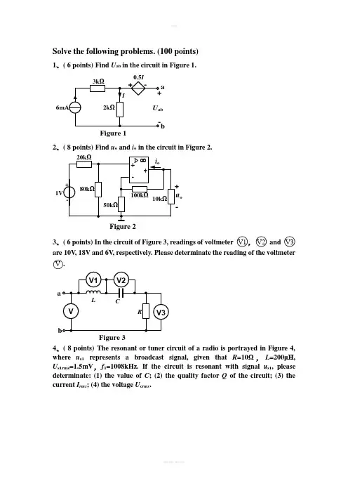
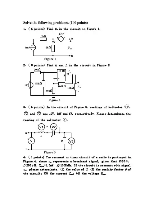
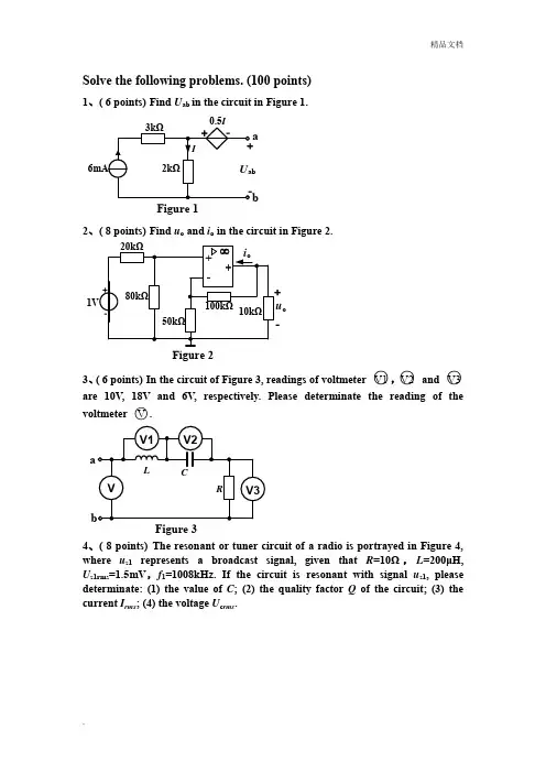
Solve the following problems. (100 points)1、( 6 points) Find U ab in the circuit in Figure 1.Figure 1a b2、( 8 points) Find u o and i o in the circuit in Figure 2.u o Figure 2-3、( 6 points) In the circuit of Figure 3, readings of voltmeter ○V1,○V2 and ○V3 are 10V , 18V and 6V , respectively. Please determinate the reading of the voltmeter ○V. aFigure 34、( 8 points) The resonant or tuner circuit of a radio is portrayed in Figure 4, where u s1 represents a broadcast signal, given that R =10Ω,L =200μH , U s1rms =1.5mV ,f 1=1008kHz. If the circuit is resonant with signal u s1, please determinate: (1) the value of C ; (2) the quality factor Q of the circuit; (3) the current I rms ; (4) the voltage U c rms .Figure 4u5、( 8 points) A balanced three-phase circuit is shown in Figure 5. Calculate the phase currents and voltages in the delta-connected load Z, if V U A ︒∠=•0220, Z =(24+j15)Ω,Z L =(1+j1)Ω.Figure 5•6、( 8 points) Find the yparameters for the circuit in Figure 6.••Figure 67、( 15 points) For the circuit in figure 7, find the rms value of the current i and the average power absorbed by the circuit, given that Ω10=L ω,Ω51=R ,Ω202=R ,Ω20/1=C ω,V )302cos(50cos 10080)(︒+++=t t t u s ωω.Figure 72u s8、( 12 points) In the circuit of Figure 8, determinate the value of Z that will absorb the maximum power and calculate the value of the maximum power.Figure 8V ︒∠050ω=103•rms9、( 14 points) If the switch in Figure 9 has been closed for a long time and is opened at t = 0, find u c , i L , u k for t ≥ 0.20Figure 9u c +-10、( 15 points) The switch in Figure 10 has been in position a for a long time. At t = 0, it moves to position b. Find i 2(t) for t ≥ 0 and sketch it. (Attention: Please markthe key data in your graph.)Figure 1010ΩSolve the following problems. (100 points)1、( 6 points) Find U ab in the circuit in Figure 1.Figure 1a bSolution:U ab = 9V2、( 8 points) Find u o and i o in the circuit in Figure 2.u o Figure 2-Solution:V 4.2=o u , 0.256mA -=o i3、( 6 points) In the circuit of Figure 3, readings of voltmeter ○V1,○V2 and ○V3 are 10V , 18V and 6V , respectively. Please determinate the reading of the voltmeter ○V. aFigure 3Solution:The reading of the voltmeter ○V is 10V .4、( 8 points) The resonant or tuner circuit of a radio is portrayed in Figure 4, where u s1 represents a broadcast signal, given that R =10Ω,L =200μH , U s1rms =1.5mV ,f 1=1008kHz. If the circuit is resonant with signal u s1, please determinate: (1) the value of C ; (2) the quality factor Q of the circuit; (3) the current I rms ; (4) the voltage U c rms .Figure 4uSolution:pF 5.12)1(≈C 6.126)2(≈Q μA 150)3(=rms I mV 190)4(=Crms U5、( 8 points) A balanced three-phase circuit is shown in Figure 5. Calculate the phase currents and voltages in the delta-connected load Z, if V U A ︒∠=•0220, Z =(24+j15)Ω,Z L =(1+j1)Ω.Figure 5•Solution:A 3.69-11.74''︒∠=•B A I , V 31.28332''︒∠=•B A U6、( 8 points) Find the y parameters for the circuit in Figure 6.••Figure 6Solution:[]S y ⎥⎦⎤⎢⎣⎡=0.5 40.02 2.07、( 15 points) For the circuit in figure 7, find the rms value of the current i and theaverage power absorbed by the circuit, given that Ω10=L ω,Ω51=R ,Ω202=R ,Ω20/1=C ω,V)302cos(50cos 10080)(︒+++=t t t u s ωω.Figure 72u sSolution:A 17.6357.2714.42.3222222120=++=++=I I I I rmsP =P 0+P 1+P 2=256+333.28+50=639.28W8、( 12 points) In the circuit of Figure 8, determinate the value of Z that will absorbthe maximum power and calculate the value of the maximum power.Figure 8V ︒∠050ω=103•rmsSolution:If Ω135jZ Z eq+==*, Z will absorb the maximum average power. The maximum average power is, W 7.2491356.1941412max=⋅=⋅=*eq OC R U P9、( 14 points) If the switch in Figure 9 has been closed for a long time and isopened at t = 0, find u c , i L , u k for t ≥ 0.20Figure 9u c +-Solution:0 A,5.15.1)5.10(5.14040>-=-+=--t e e i t t L , 0 V,60120)12060(12020/20/>-=-+=--t e e u t t C 0 ,V 6030902020/40>+--=-=--t e e u i u t t C L K10、( 15 points) The switch in Figure 10 has been in position a for a long time. At t = 0, it moves to position b. Find i 2(t) for t ≥ 0 and sketch it. (Attention: Please mark the key data in your graph.)Figure 1010ΩSolution: A 25.125.132t t e e i ---= 打发第三方.。

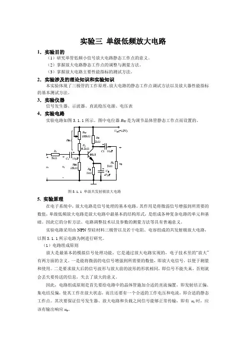
实验三单级低频放大电路1.实验目的(1)研究单管低频小信号放大电路静态工作点的意义。
(2)掌握放大电路静态工作点的调整与测量方法。
(3)掌握放大电路主要性能指标的测试方法。
2.实验涉及的理论知识和实验知识本实验体现了三极管的工作原理、放大电路的静态工作点调试方法以及放大器性能指标的基本测试方法。
3.实验仪器信号发生器、示波器、直流稳压电源、电压表4.实验电路实验电路如图3.1.1所示。
图中电位器R W是为调节晶体管静态工作点而设置的。
O图3.1.1单级共发射极放大电路5. 实验原理在电子系统中,放大电路是信号处理的基本电路。
其作用是将微弱信号增强到所需要的数值,单级低频放大电路是放大电路中最基本的结构形式,是组成各种复杂电路的单元和基础。
因此它的分析方法、电路调整技术以及参数的测量方法等具有普遍意义。
实验电路采用由NPN型硅材料三极管以及若干电阻、电容组成的共发射极放大电路,以图3.1.1所示电路为例进行研究。
(1)电路组成原则放大是最基本的模拟信号处理功能,它是通过放大电路实现的,电子技术里的“放大”有两方面的含义。
一是能将微弱的电信号增强到所需要的数值,即放大电信号,以便于测量和使用。
二是要求放大后的信号波形与放大前的波形的形状相同,即信号不能失真,否则就会丢失要传送的信息,失去了放大的意义。
因此,电路组成原则是首先要给电路中的晶体管施加合适的直流偏置,即发射结正偏、集电结反偏,使其工作在放大状态,而且还要有一个合适的工作电压和电流,即合适的静态工作点。
其次要保证信号发生器、放大电路和负载之间信号能够正常传输,即有u i时,应该有输出响应u o。
1)直流偏置原则图3.1.1所示电路采用的是电阻分压式偏置方法,通过基极偏置电阻R B1和R B2对U CC分压,获得晶体管的基极电压U BQ ,保证晶体管的发射结正偏。
U CC 是集电极电源,它通过R C 加至晶体管的集电极,保证晶体管的集电结加反向电压。


单片机笔记
Vfd荧光显示管
片内固话应用软件和系统软件
芯片制造工艺80c51低功耗
4krom
125字节RAM
两个十六位定时/计数器
64k字节总线扩展控制
可编程i/o口4*8位
可编程串行口
程序计数器16位对64kROM直接寻址PC第八位由p0输出,高八位由p2输出MCS-51高增益反相放大器
输出端XTAL1,外接晶振
输入端XTAL2,外部振荡器
32条可编程I/O口线
4个八位并行I/O端口
五个中断,两个优先级
串行通信接收RXD
串行通信发送TXD
中断申请INTO0
中断申请INTO1
外部RAM写选通WR
外部RAM读选通RD
EA=1从内部ROM开始
EA=0从外部ROM开始PROG编程脉冲输入端
PSEN访问外部程序存储器选通外部中断,0,1
T0,1,2中断
串行口中断
专用功能寄存器区sfr锁存器,定时器,串行数据缓冲器,各种控制寄存器,状态寄存器
程序状态控制字rsw
数据指针dptr,访问外部ram。
Solve the following problems. (100 points)1、( 6 points)Find U ab in the circuit in Figure 1.Figure 1a b2、( 8 points)Find u o and i o in the circuit in Figure 2.u oFigure 2-3、( 6 points)In the circuit of Figure 3, readings of voltmeter ○V1,○V2and○V3 are 10V, 18V and 6V, respectively. Please determinate the reading of the voltmeter ○V.aFigure 34、( 8 points)The resonant or tuner circuit of a radio is portrayed in Figure 4, where u s1 represents a broadcast signal, given that R=10Ω,L=200μH, Us1rms=1.5mV,f1=1008kHz. If the circuit is resonant with signalus1, please determinate: (1) the value of C; (2) the quality factor Q of the circuit; (3) the current I rms; (4) the voltage U c rms.Figure 4u5、( 8 points) A balanced three-phase circuit is shown in Figure 5. Calculate the phase currents and voltages in the delta-connected load Z, if V U A ︒∠=•0220, Z =(24+j15)Ω,Z L =(1+j1)Ω.Figure 5•6、( 8 points) Find they parameters for the circuit in Figure 6.••Figure 67、( 15 points) For the circuit in figure 7, find the rms value of the current i and the average power absorbed by the circuit, given that Ω10=L ω,Ω51=R ,Ω202=R ,Ω20/1=C ω,V )302cos(50cos 10080)(︒+++=t t t u s ωω.Figure 72u s8、( 12 points) In the circuit of Figure 8, determinate the value of Z that will absorb the maximum power and calculate the value of the maximum power.Figure 8V ︒∠050ω=103•rms9、( 14 points) If the switch in Figure 9 has been closed for a long time and is opened at t = 0, find u c , i L , u k for t ≥ 0.20Figure 9u c +-10、( 15 points) The switch in Figure 10 has been in position a for a long time. At t = 0, it moves to position b. Find i 2(t) for t ≥ 0 and sketch it. (Attention: Please mark the key data in your graph.)Figure 1010ΩSolve the following problems. (100 points)1、( 6 points) Find U ab in the circuit in Figure 1.Figure 1a bSolution:U ab = 9V2、( 8 points) Find u o and i o in the circuit in Figure 2.u o Figure 2-Solution:V 4.2=o u , 0.256mA -=o i3、( 6 points) In the circuit of Figure 3, readings of voltmeter ○V1,○V2 and ○V3 are 10V, 18V and 6V, respectively. Please determinate the reading of the voltmeter ○V .aFigure 3Solution:The reading of the voltmeter ○V is 10V .4、( 8 points) The resonant or tuner circuit of a radio is portrayed in Figure 4, where u s1 represents a broadcast signal, given that R =10Ω,L =200μH , U s1rms =1.5mV ,f 1=1008kHz. If the circuit is resonant with signal u s1, please determinate: (1) the value of C ; (2) the quality factor Q of the circuit; (3) the current I rms ; (4) the voltage U c rms .Figure 4uSolution:pF 5.12)1(≈C 6.126)2(≈Q μA 150)3(=rms I mV 190)4(=Crms U5、( 8 points) A balanced three-phase circuit is shown in Figure 5. Calculate the phase currents and voltages in the delta-connected load Z, if V U A ︒∠=•0220, Z =(24+j15)Ω,Z L =(1+j1)Ω.Figure 5•Solution:A 3.69-11.74''︒∠=•B A I , V 31.28332''︒∠=•B A U6、( 8 points) Find the y parameters for the circuit in Figure 6.••Figure 6Solution:[]S y ⎥⎦⎤⎢⎣⎡=0.5 40.02 2.07、( 15 points) For the circuit in figure 7, find the rms value of thecurrent i and the average power absorbed by the circuit, given that Ω10=L ω,Ω51=R ,Ω202=R ,Ω20/1=C ω,V)302cos(50cos 10080)(︒+++=t t t u s ωω.Figure 72u sSolution:A 17.6357.2714.42.3222222120=++=++=I I I I rmsP =P 0+P 1+P 2=256+333.28+50=639.28W8、( 12 points) In the circuit of Figure 8, determinate the value of Zthat will absorb the maximum power and calculate the value of the maximum power.Figure 8V ︒∠050ω=103•rmsSolution:If Ω135jZ Z eq+==*, Z will absorb the maximum average power. The maximum average power is, W 7.2491356.1941412max=⋅=⋅=*eq OC R U P9、( 14 points) If the switch in Figure 9 has been closed for a long timeand is opened at t = 0, find u c , i L , u k for t ≥ 0.20Figure 9u c +-Solution:0 A,5.15.1)5.10(5.14040>-=-+=--t e e i t t L , 0 V,60120)12060(12020/20/>-=-+=--t e e u t t C 0 ,V 6030902020/40>+--=-=--t e e u i u t t C L K10、( 15 points) The switch in Figure 10 has been in position a for a long time. At t = 0, it moves to position b. Find i 2(t) for t ≥ 0 and sketch it. (Attention: Please mark the key data in your graph.)Figure 1010ΩSolution: A 25.125.132t t e e i ---= 打发第三方(注:专业文档是经验性极强的领域,无法思考和涵盖全面,素材和资料部分来自网络,供参考。

单级低频电压放大电路第一篇:单级低频电压放大电路单片机笔记 Vfd荧光显示管片内固话应用软件和系统软件芯片制造工艺80c51低功耗 4krom 125字节RAM 两个十六位定时/计数器 64k字节总线扩展控制可编程i/o口4*8位可编程串行口程序计数器16位对64kROM直接寻址 PC第八位由p0输出,高八位由p2输出 MCS-51高增益反相放大器输出端XTAL1,外接晶振输入端XTAL2,外部振荡器32条可编程I/O口线4个八位并行I/O端口五个中断,两个优先级串行通信接收RXD 串行通信发送TXD 中断申请INTO0 中断申请INTO1 外部RAM写选通WR 外部RAM读选通RD EA=1从内部ROM开始 EA=0从外部ROM开始 PROG编程脉冲输入端PSEN访问外部程序存储器选通外部中断,0,1 T0,1,2中断串行口中断专用功能寄存器区sfr锁存器,定时器,串行数据缓冲器,各种控制寄存器,状态寄存器程序状态控制字rsw 数据指针dptr,访问外部ram第二篇:单级低频放大电路实验三单级低频放大电路1.实验目的(1)研究单管低频小信号放大电路静态工作点的意义。
(2)掌握放大电路静态工作点的调整与测量方法。
(3)掌握放大电路主要性能指标的测试方法。
2.实验涉及的理论知识和实验知识本实验体现了三极管的工作原理、放大电路的静态工作点调试方法以及放大器性能指标的基本测试方法。
3.实验仪器信号发生器、示波器、直流稳压电源、电压表4.实验电路实验电路如图3.1.1所示。
图中电位器RW是为调节晶体管静态工作点而设置的。
RB1 RW 100kΩ Ucc(+12V)RC 2kΩ Rs + 3kΩ usRB2 18kΩ R1 6.2kΩ 9013 + C2 10μF + + RL 2kΩ uO CE 47μF RE 1kΩ 图3.1.4 输入电阻测量原理图图3.1.5 输出电阻测量原理图在被测放大电路前加一个电阻R,输入正弦信号,用示波器分别测量R两端对地的电压us和ui。
Solve the following problems. (100 points)1、( 6 points) Find U ab in the circuit in Figure 1.Figure 1a b2、( 8 points) Find u o and i o in the circuit in Figure 2.u o Figure 2-3、( 6 points) In the circuit of Figure 3, readings of voltmeter ○V1,○V2 and ○V3 are 10V , 18V and 6V , respectively. Please determinate the reading of the voltmeter ○V.aFigure 34、( 8 points) The resonant or tuner circuit of a radio is portrayed in Figure 4, where u s1 represents a broadcast signal, given that R =10Ω,L =200μH , U s1rms =1.5mV ,f 1=1008kHz. If the circuit is resonant with signal u s1, please determinate: (1) the value of C ; (2) the quality factor Q of the circuit; (3) the current I rms ; (4) the voltage U c rms .Figure 4u5、( 8 points) A balanced three-phase circuit is shown in Figure 5. Calculate the phase currents and voltages in the delta-connected load Z, if V U A ︒∠=∙0220, Z =(24+j15)Ω,Z L =(1+j1)Ω.Figure 5∙6、( 8 points) Find the yparameters for the circuit in Figure 6.∙∙Figure 67、( 15 points) For the circuit in figure 7, find the rms value of the current i and the average power absorbed by the circuit, given that Ω10=L ω,Ω51=R ,Ω202=R ,Ω20/1=C ω,V )302cos(50cos 10080)(︒+++=t t t u s ωω.Figure 72u s8、( 12 points) In the circuit of Figure 8, determinate the value of Z that will absorb the maximum power and calculate the value of the maximum power.Figure 8V ︒∠050ω=103∙rms9、( 14 points) If the switch in Figure 9 has been closed for a long time and is opened at t = 0, find u c , i L , u k for t ≥ 0.20Figure 9u c +-10、( 15 points) The switch in Figure 10 has been in position a for a long time. At t = 0, it moves to position b. Find i 2(t) for t ≥ 0 and sketch it. (Attention: Pleasemark the key data in your graph.)Figure 1010ΩSolve the following problems. (100 points)1、( 6 points) Find U ab in the circuit in Figure 1.Figure 1a bSolution:U ab = 9V2、( 8 points) Find u o and i o in the circuit in Figure 2.u o Figure 2-Solution:V 4.2=o u , 0.256mA -=o i3、( 6 points) In the circuit of Figure 3, readings of voltmeter ○V1,○V2 and ○V3 are 10V , 18V and 6V , respectively. Please determinate the reading of the voltmeter ○V.aFigure 3Solution:The reading of the voltmeter ○V is 10V .4、( 8 points) The resonant or tuner circuit of a radio is portrayed in Figure 4, where u s1 represents a broadcast signal, given that R =10Ω,L =200μH , U s1rms =1.5mV ,f 1=1008kHz. If the circuit is resonant with signal u s1, please determinate: (1) the value of C ; (2) the quality factor Q of the circuit; (3) the current I rms ; (4) the voltage U c rms .Figure 4uSolution:pF 5.12)1(≈C 6.126)2(≈Q μA 150)3(=rms I mV 190)4(=Crms U5、( 8 points) A balanced three-phase circuit is shown in Figure 5. Calculate the phase currents and voltages in the delta-connected load Z, if V U A ︒∠=∙0220, Z =(24+j15)Ω,Z L =(1+j1)Ω.Figure 5∙Solution:A 3.69-11.74''︒∠=∙B A I , V 31.28332''︒∠=∙B A U6、( 8 points) Find the y parameters for the circuit in Figure 6.∙∙Figure 6Solution:[]S y ⎥⎦⎤⎢⎣⎡=0.5 40.02 2.07、( 15 points) For the circuit in figure 7, find the rms value of the current i andthe average power absorbed by the circuit, given that Ω10=L ω,Ω51=R ,Ω202=R ,Ω20/1=C ω,V)302cos(50cos 10080)(︒+++=t t t u s ωω.Figure 72u sSolution:A 17.6357.2714.42.3222222120=++=++=I I I I rmsP =P 0+P 1+P 2=256+333.28+50=639.28W8、( 12 points) In the circuit of Figure 8, determinate the value of Z that willabsorb the maximum power and calculate the value of the maximum power.Figure 8V ︒∠050ω=103∙rmsSolution:If Ω135jZ Z eq +==*, Z will absorb the maximum average power. The maximum average power is, W 7.2491356.1941412max=⋅=⋅=*eq OC R U P9、( 14 points) If the switch in Figure 9 has been closed for a long time and isopened at t = 0, find u c , i L , u k for t ≥ 0.20Figure 9u c +-Solution:0 A,5.15.1)5.10(5.14040>-=-+=--t e e i t t L , 0 V,60120)12060(12020/20/>-=-+=--t e e u t t C 0 ,V 6030902020/40>+--=-=--t e e u i u t t C L K10、( 15 points) The switch in Figure 10 has been in position a for a long time. At t = 0, it moves to position b. Find i 2(t) for t ≥ 0 and sketch it. (Attention: Pleasemark the key data in your graph.)Figure 1010ΩSolution: A 25.125.132t t e e i ---=打发第三方。

实验7 单管低频电压放大电路实验目的1.认识实验所用的电子元器件(双极型晶体管、电阻、电位器和电容器等)。
2.学习看图接线,能熟练使用常用电子测量仪器。
3.学习单管电压放大电路的基本测试方法。
4.了解双极型晶体管电压放大电路中引入负反馈后对其工作性能的影响。
实验原理1. 单管低频电压放大电路介绍Oe CC图3.7a.1单管低频电压放大电路阻容耦合分压偏置共发射极电压放大电路如图3.7a.1所示。
该电路中的双极型晶体管T 是电路中的放大器件,它能把输入回路(基极—发射极)中微小的电流信号在输出回路中(集电极—发射极)放大为一定大小的电流信号。
输出回路中得到的较大输出电流是源自直流电源,双极型晶体管在电路中实际上起着电流控制作用。
电源提供放大电路能量,还为双极型晶体管的集电极提供反向偏置,使其处于放大工作状态;并通过基极电阻R CC U B1 和R B2的分压,提供合适的基极电压,调节电位器R P 的阻值可以改变基极电流,从而改变集电极电流。
集电极电阻R C 可以将集电极电流的变化变换为集电极电压的变化,在输出回路中得到放大的电压信号。
发射极电阻R E 对集电极电流的直流分量有负反馈的作用,稳定了静态工作电流。
发射极电容C E 对集电极电流的交流分量提供了交流通路,起了分流交流作用。
C 1、C 2能够分隔直流电位,通过交流分量电流,起到隔直流通交流的作用;它们分别把交流信号电流输入基极以及把放大后的交流信号电压送到负载端,而不影响晶体管的直流工作状态。
2. 静态工作点Q 的估算当外加输入信号为零时,在直流电源的作用下,基极和集电极回路的直流电流和电压分别用I BQ 、U BEQ 、I CQ 、U CEQ 表示,并在其输入和输出特性上各自对应一个点,称为静态工作点。
此时电路的直流通路如图3.7a.2所示。
假设,则有 1BQ BE 0.7I I U >>,=V B2BQCC B1B2R U R R ≈+ , BQ BE EQ E U U I R −=, EQ BQ 1I I β=+ 由于CQ EQ I I ≈, CEQ CC CQ C E ()U U I R R ≈−+R 1.5k 1I TCC图3.7a.2电压放大电路的直流通路3. 静态工作点的选择放大器静态工作点Q 的位置对放大器放大信号有很大影响,从图3.7a.3的输出特性图上能直观地看到。
东南大学电工电子实验中心
实验报告
课程名称:模拟电子电路实验
第三次实验
实验名称:单极低频电压放大电路(基础)院(系):仪器科学与工程学院专业:
姓名:学号:
实验室: 实验组别:
同组人员:实验时间:
评定成绩:审阅教师:
实验三 单级低频电压放大电路(基础)
一、实验目的
1、 掌握单级放大电路的工程估算、安装和调试;
2、 了解三极管各项基本器件参数、工作点、偏置电路、输入阻抗、输出阻抗、增益、幅频
特性等的基本概念以及测量方法;
3、 掌握基本的模拟电路的故障检查和排除方法,深化示波器、稳压电源 、交流电压表、
函数发生器的使用技能训练。
二、实验原理
1、 对于上图中的偏置电路,只有R 2支路中的电流I 1>>I BQ 时,才能保证V BQ 恒定实现自动
稳定工作点的作用,所以工程中一般取:1(5~10)BQ I I =(硅管)
1(10~20)BQ I I =(锗管)
2、 为了提高电路的稳定性,一般要求V BQ >>V BE ,工程中一般取V BQ =(5~10)V BE ,即V BQ =(3~
5)V (硅管),V BQ =(1~3)V (锗管) 3、 电路的静态工作点电流 BQ BE
CQ E
V V I R -≈
由于是小信号放大,所以I CQ 一般取0.5~2mA
4、 I CQ 确定后通过以下公式可计算R 1和R 2的值:
21
(5~10)(5~10)B Q B Q B Q
B Q
C Q
V V V
R I I I β⋅=
=
=
2
11
()CC BQ
CC BQ BQ
V V V V R R I V --≈
=
5、 交流电压放大倍数'
''26(1)300(1)
L
L L
V be
b e
CQ
R R R A mV r r r I βββββ⋅⋅⋅=-
=-=-
++++ 6、 交流输入阻抗1226////(1)300(1)
i be be b e CQ
mV
R r R R r r r I ββ=≈=++=++
7、 交流输出阻抗//O o C C R r R R =≈
三、预习思考 1、 器件资料:
上网查询本实验所用的三极管9013的数据手册,画出三极管封装示意图,标出每个管脚的名称,将相关参数值填入下表:
2、 偏置电路:
教材图1中偏置电路的名称是什么,简单解释是如何自动调节BJT 的电流I C 以实现稳定直流工作点的作用的,如果R 1 、R 2取得过大能否再起到稳定直流工作点的作用,为什么?
答:共发射极偏置电路。
此电路是分压偏置电路,Ub ≈R2/(R1+R2) ⋅Vcc,当环境温度改变时,此电路可自动调Ic 达到稳定直流工作点的作用。
如果R1,R2取得过大,则1I 减小,在温度变化时VBQ 无法保持不变,也就不能起到稳定直流工作点的作用。
3、 电压增益:
(I) 对于一个低频放大器,一般希望电压增益足够大,根据您所学的理论知识,分析有
哪些方法可以提高电压增益,分析这些方法各自优缺点,总结出最佳实现方案。
答:'
''
26(1)300(1)
L
L L
V be
b e
CQ
R R R A mV r r r I βββββ⋅⋅⋅=-
=-=-
++++ 所以提高电压增益的方法有:
1)增大集电极电阻RC 和负载RL 。
缺点:RC 太大,受VCC 的限制,会使电路不能正常工作。
2)Q 点适当选高,即增大ICQ 。
缺点:电路耗电大、噪声大
(II) 实验中测量电压增益的时候用到交流毫伏表,试问如果用万用表或示波器可不可
以,有什么缺点。
答:在频率低于100KHZ时万用表的交流档和交流毫伏表都可以比较精确地测量交流电压,当频率大于100KHZ小于1MHZ时,万用表的测量精度下降,只能采用交流毫伏表测量,对于更高频率的信号,必须选择高频毫伏表测量。
而示波器测量的电压精度一般比毫伏表低一个数量级,无法在需要精确测量电压值时的时候使用。
4、输入阻抗:
(I)放大器的输入电阻R i反映了放大器本身消耗输人信号源功率的大小,设信号源内阻
为R S,试画出图2中放大电路的输入等效电路图,回答下面的连线题,并做简单解释:
R i = R S放大器从信号源获取较大电压
R i << R S放大器从信号源吸取较大电流
R i >> R S放大器从信号源获取最大功率答:根据教材图2可得:
对Pi关于Ri求导,当Ri=Rs时,Pi=0,所以放大器从信号源获取最大功率。
(II)教材图2是实际工程中测量放大器输入阻抗的原理图,试根据该图简单分析为什么串接电阻R S的取值不能太大也不能太小。
图2 放大器输入阻抗测量原理图
答:若Rs取得过大,不满足当iRR>>条件,较小,则放大器从信号源获取较小电压,电压表测量小信号的时候由于噪声干扰等原因测量精度下降,测量误差增加。
若RS取得过小,又不满足iUiRR<<条件,则放大器从信号源获取较小电流,值将很大,同样会引入较大误差。
(III)对于小信号放大器来说一般希望输入阻抗足够高,根据您所学的理论知识,分析有哪些方法可以提高教材图1-3中放大电路的输入阻抗。
答:
提高放大电路的输入阻抗方法:
A.适当增大R1,R2的电阻值
B.使用电流放大系数(β)大的三极管。
C.降低静态工作点,在输出信号不失真的情况下。
5、输出阻抗:
(I)放大器输出电阻R O的大小反映了它带负载的能力,试分析教材图2中放大电路的
输入阻抗受那些参数的影响,设负载为R L,画出输出等效电路图,回答下面的连线题,并做简单解释。
R O = R L负载从放大器获取较大电压
R O << R L负载从放大器吸取较大电流
R O >> R L负载从放大器获取最大功率答:根据教材图可得:
当Ro=RL时,负载从放大器获取最大功率。
(II)图3是实际工程中测量放大器输出阻抗的原理图,试根据该图简单分析为什么电阻R L的取值不能太大也不能太小。
图3 放大器输出阻抗测量原理图
答:若RL取值过大,电流源的电流只有一小部分流经RL,输出电流过小。
但若RL过小,则通过RL的电流即通过集电极端的电流过大,将会损坏三极管。
(III)对于小信号放大器来说一般希望输出阻抗足够小,根据您所学的理论知识,分析有哪些方法可以减小教材图1-3中放大电路的输出阻抗。
答:适当减小Rc的电阻值
6、计算教材图1中各元件参数的理论值,其中
已知:V CC=12V,V i=5mV,R L=3KΩ,R S=50Ω,T为9013
指标要求:A V>50,R i>1 KΩ,R O<3KΩ,f L<100Hz,f H>100kHz(建议I C取2mA)
答:β=263
BQ BE
CQ E
V V I R -≈
取IC=2mA
I CQ 确定后通过以下公式可计算R 1和R 2的值: 21
(5~10)(5~10)B Q B Q B Q
B Q
C Q
V V V
R I I I β⋅=
=
=
2
11
()CC BQ
CC BQ BQ
V V V V R R I V --≈
=
交流电压放大倍数'''26(1)300(1)
L
L L
V be
b e
CQ
R R R A mV r r r I βββββ⋅⋅⋅=-
=-=-
++++=-105.7 交流输入阻抗1226////(1)300(1)i be be b e CQ
mV
R r R R r r r I ββ=≈=++=++=3.73k 交流输出阻抗//O o C C R r R R =≈=3k
四、实验内容 1、
(I)
图1 截止失真输出波形
图2 完全截止失真输出波形
图3 饱和失真输出波形
图4:完全饱和失真输出波形
五、思考题
1、如将实验电路中的NPN管换为PNP管,试问:
(1)这时电路要作哪些改动才能正常工作?
答:将+Vcc改为‐Vcc, C1,C2,CE反接
(2)经过正确改动后的电路其饱和失真和截止失真波形是否和原来相同?为什么?
答:不同,这时底部失真为截止失真,顶部失真为饱和失真(与NPN管相反),输入输出波形仍为反相。
对于PNP管来说出现底部失真时,表明集电极电压达到最小值,此时集电极电流很小,为截止失真;而出现顶部失真时,表明集电极电压达到最大值,此时集电极电流达到饱和,对应为饱和失真。
2、图1-3电路中上偏置串接R1’起什么作用?
答:防止调整RW为零电阻时,IB上升,发射结电流过大损坏PN结
3、在实验电路中,如果电容器C2漏电严重,试问当接上RL后,会对放大器性能产生哪些影响?
答:电路的静态工作点ICQ,VCEQ将受到影响,输出电压V0由于漏电电阻的分压作用而使V0下降。