TOTA-1000A系列嵌入式数字硬盘录像机
- 格式:pdf
- 大小:5.38 MB
- 文档页数:85
OK系列千兆网摄像头使用手册2018.01北京嘉恒中自图像技术有限公司是国内领先的数字图像产品供应商,总部位于中关村中科院自动化研究所,是一家聚集了大批业内技术精英,以自主研发为核心竞争力的股份制高新技术企业。
我们的前身是中科院自动化所图像部及后来成立的科技嘉仪器仪表有限公司。
我公司研发骨干主要来自中科院研究所和重点高校,具有扎实的技术实力,丰富的产品开发经验和良好的用户服务信誉。
嘉恒图像是国内最早的专业图像卡生产商,也是国内为数不多的能够自主研发各种高性能 CCD 和CMOS 摄像头产品及 DSP,FPGA 图像处理和采集产品的公司之一。
目前,我们的主要产品系列有图像采集卡、工业摄像头、嵌入式专用图像采集处理器及基于 DSP 技术的图像采集处理产品等,广范应用于医学影像,生物技术,工业检测,智能交通,保安监控,金融票证,动态分析等领域。
我们根据客户的应用需求,提供各种普及档、中档和高档的图像产品,同时提供强大的技术支持和研发定制服务。
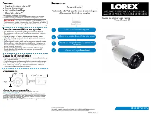
OK千兆网摄像头完全由嘉恒图像自主研发,该系列产品具有以下特点:相较市面上使用软件实现GigE Vision协议的摄像头,我们采用硬件实现,处理速度更快;能与第三方软件完全兼容;具有重传、续传功能,保证数据不丢包;CRC校验,保证数据的正确性和可靠性;同时还支持热插拔,方便用户使用。
了解更多嘉恒图像OK千兆网摄像头的详细信息及使用指南,请阅读本手册,也可登陆嘉恒网站或致电************进行咨询。
注意1保持摄像头干燥,禁止淋雨或放在潮湿的地方;2摄像头不使用时,应将镜头取下,盖上摄像头盖放好;3请勿使用不合格电源给摄像头供电,摄像头供电电压应为12伏(最大不能超过15伏),输出电流应不小于1.2安;4请勿将摄像头长时间的对准强光(例如太阳光),这样可能会导致CCD传感器过度饱和造成永久性损坏;5请勿擅自拆卸、修理和组装摄像头,有任何问题请联系北京嘉恒中自图像技术公司技术支持;6请勿使用手指或者坚硬物体接触CCD的保护玻璃。
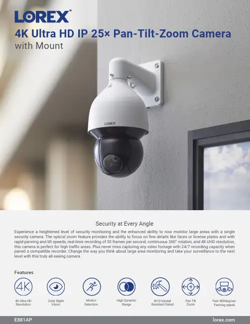
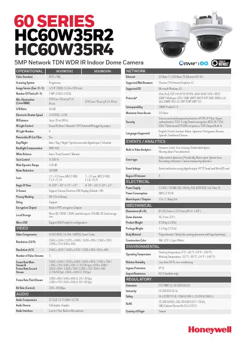
4K Ultra HD IP 25× Pan-Tilt-Zoom Camerawith MountExperience a heightened level of security monitoring and the enhanced ability to now monitor large areas with a single security camera. The optical zoom feature provides the ability to focus on fine details like faces or license plates and with rapid panning and tilt speeds, real-time recording of 30 frames per second, continuous 360° rotation, and 4K UHD resolution, this camera is perfect for high traffic areas. Plus never miss capturing any video footage with 24/7 recording capacity when paired a compatible recorder. Change the way you think about large area monitoring and take your surveillance to the next level with this truly all-seeing camera.Security at Every AngleFeatures4K Ultra HDResolution High DynamicRange Fast 400deg/sec Panning speedPan Tilt Zoom Color NightVision MotionDetection IK10 Vandal Resistant RatedPicture PerfectSee every detail with superior definitionColor Night VisionSee everything clear as day, even at nightNo Matter the WeatherMaximize coverage with cameras built for any climatePan. Tilt. Optical ZoomSee more, know more with Pan and Tilt Capabilities• 4K (8MP) Ultra HD resolution, ensuring clear and detailed footage• See more with a with up to 66° field of view, depending on the level ofzoom desired• Record at a real-time 30 frames-per-second, providing smooth andclearer footage• Experience enhanced nighttime clarity and better video evidencewith Color Night Vision²• Up to 150ft (46m) IR night vision in low light and 98ft (30m) in totaldarkness³• Weatherproof rated (IP67)• Operates in temperatures low as -40°F (-40°C) and high as 131˚F (55 ˚C)• Durable camera housing, designed to withstand harsh weather conditions• Be confident that this micro security camera is capable of looking afteritself. It is engineered with an IK10 vandal resistant rating - meaning itsresilient metal housing is made to withstand all types of violent impacts• Get the full picture with the endless 360° Pan range and• Fast 400°/sec panning speed and tilt capabilities allows the cameras tocover larger areas of your property• 25X Optical Zoom through the Lorex App, provides an added level of clarity• Program preset viewing points, patterns, scan cycles and tours whenconnected to a compatible NVRProduct SpecificationsSpecification Video Transmission Technology IPImage Sensor 8MP/4K 1/1.8" CMOS Video Format NTSCVideo Compression H.265/H.264H(Main Stream & Sub Stream)OpticalViewing Angle (Horizontal)61.6°– 3.6°Viewing Angle (Diagonal)66.6°– 4°Lens/Lens type 5.3-135mm F1.6- F4.0 / Zoom Module Optical Zoom 25×Digital Zoom Yes 5Pan/Tilt CapabilitiesPan / Tilt Range Pan: 0°–360° endless Tilt: -15° ~ 90°Auto Flip Yes, 180° Continous Rotation YesManual Speed (Maximum) Pan: 0.1°–300°/s Tilt: 0.1°–200°/s Preset Speed (Maximum) Pan: 400°/s; Tilt: 300°/s Presets 300Patterns 5Tours 8Other PTZ Functions Auto Scans, Auto Pan Camera OSD YesSpecial Features Motion DetectionYes Disclaimers:1. Compatible with select Lorex analog HD recorders. For a full list of compatible recorders visit: /compatibility2. Full color nighttime video typically switches to black & white IR night vision below 1 lux to ensure optimal low-light image quality.3. Stated IR illumination range is based on ideal conditions in typical outdoor night time ambient lighting and in total darkness. Actual range and image clarity depend on the installation location, viewing area, and light reflection/absorption level of an object. In low light, the camera will switch to black and white.4. Not intended for submersion in water. Installation in a sheltered area recommended.5. Digital zoom is a function controlled by the connected NVR. For a list of compatible NVRs visit: /compatibility6. A Cat5e cable is required to connect to a compatible NVR. Not included.*A microSD card can be inserted for independent recording. Data can be accessed through the camera using a web browser but will not upload to the NVR or to the cloud for mobile app viewing.Lorex products are designed for consumer and business use only and not for US federal governments, federally-funded projects or contractors subject to NDAA.Model InformationE881AP4K Ultra HD IP 25× PTZ Camera6-95529-02868-2DimensionsPackage Brown box Package Weight 15.6lb / 7.1kg Package Dimensions (W × D × H)10.6 × 10.6 × 25.6” / 270 × 270 × 650mm Package Cube1.67 cbf / 0.047cbmLorex Corporation10440 Little Patuxent Parkway, Ste, 300,Columbia, MD 21044, United States© 2022 Lorex CorporationAs our product is subject to continuous improvement, Lorex Technology & subsidiaries reserve the right to modifyE881AP 1 × Installation Kit What’s in the box1 × PTZ Camera 1 × Wall Mount 1 × Power Adapter 1 × Safety ChainQuick Setup GuideVideo Output Resolution/Frame rate Up to 4K (8MP) @ 30fps Effective Pixels H:3840 × V:2160HDR Yes Termination RJ45NightVision Night Vision Range 150ft (46m)/ 98ft (30m)Color Night Vision Yes GeneralBody MaterialAluminum Alloy Vandal Resistant Rating IK10SD Card Slot Yes*Power Requirements PoE Plus (Power over Ethernet Plus Class -802.3at)/24W Power Consumption (max)1A / 24W Camera Dimensions (W × H) 6.5 × 13" / 331 × 165mm Camera Weight 11.7lb / 5.3kgOperating Temperature -40°F ~ 158°F /-40°C ~ 70°C Humidity< 95% RH。
1 IntroductionFeatures 3Components 4System Configuration 52 RS485 and PTZ BasicsPhysical Connection 6Multiple PTZ Setup 7ID, Protocol, Baud Rate 93 InstallationCeiling Mount 104 Camera AddressingCamera Address Setting 11 Protocol and Baud Rate Settings 135 Basic FunctionsSelecting Camera14Setting Presets15Calling Presets15Clearing Presets15Auto Cruise16Auto Pan166 Advanced FunctionsCamera Power 17Back Light Compensation 17Digital Zoom 17Focus Mode 17Iris Mode 18White Balance Mode 187 On Screen DisplayMain Menu 19Focus Set 20Auto White Balance 20Auto Exposure 21Special Functions 21Motion Detection 22Function On Screen Display 228 Parts Description and Function 239 Product Specifications 24Camera Specification• Sony Module 480 Lines• 27X Optical Zoom• 10X Digital Zoom• 3.25mm – 88mm Zoom• IR Sensitive• 12V DCComplete View• 360 Degree Pan, 90 Degree Tilt. For No Blind SpotsHousing• Indoor Use Only• Multiple Mounting Configurations• Operating Temperatures: 32° to 104° FPTZ Control• RS-485 Communication, MAX 31 Multi-drop• Versatile Pelco-D and Pelco P Protocol• Variable Pan and Tilt Speed• 64 Programmable Presets• OSD Setup• Programmable Cruise SequenceParts InformationItemPart No. DescriptionDome Camera and HousingACD-1000-LG27NTSC Dome Camera, Indoor Housing, Including Transparent DomePower Supply 12v DC 2.5A Power Supply ManualManual for ACD-1000-LG27Default ComponentsDome Camera and HousingAccessoriesACD-1000 ManualPower SupplyConfigurationPart DescriptionVideo OutputBlueNet Video serverBlueNet Video serverDVR DVRPTZ Controller MonitorRS-485 Input1. Mounting Base2. Outer Tube3. Shading Cover4. Outer Cover5. Camera6. Connecting CableRS-485 communicationRS-485 communication is used to control a PTZ camera. Standalone DVRs, PC-based DVRs, keyboard joystick PTZ controllers, video servers, and a variety of other CCTV equipment usually have an RS-485 interface (push terminals, D-Sub connector, etc.) for PTZ control. The CCTV equipment transmits control signals while the PTZ camera receives the signals and performs the function required.RS-485 utilizes two wires ; a ‘+’ wire and a ‘–’ wire. These two wires may also be label or reference as:• + and – • D+ and D- • A+ and B-•RS485+ and RS485-To make the physical connection from the controlling device (DVR, keyboard controller, etc.) to the PTZ, simply connect the RS485 ‘-’ from the controlling device to the RS485 ‘-’ on the PTZ. Do the same for the RS485 ‘+’. Any type of wire can be used for the connection, but 0.56mm (24AWG) twisted pair is recommended.++-- PTZ Physical ConnectionsControllerBaud Rate is the data transmission rate in bps (bits per second). Both the controlling device and PTZ must use the same baud rate. Most PTZ camera and devices default to a baud rate of 2400 bps.The maximum theoretical transmitting distances of RS-485 are below using 0.56mm (24AWG) twisted pair cable.Baud Rate Maximum Distance2400 bps 1800m 4800 bps1200m 9600 bps800mIf thinner cables are used or the dome is installed in an environment with strong electromagnetic interference or many PTZs are used on the same line, the maximum distance will be decreased.For multiple PTZ installs , RS485 standards require a daisy-chain connection between the equipment. Up to 32 devices, including the controller can be daisy-chained. A 120 Ω termination must be made on the first and last device in the chain. Most controllers are already terminated. To terminate the last PTZ in line, simply locate the 120 Ω termination resistor jumper on the PTZ’s protocol PCB and set the jumper to pins 1 & 2. By default, the PTZ is not terminated, thus having the pins on 2 & 3. For Star Configurations, see the next page.Termination Jumper Location.Continued on Next PageMultiple PTZ (cont.)Some circumstances require the use of a star configuration. The termination resistors must be set on the two devices that are the farthest distances away from each other, in this case #1 and #15 as seen below.As the star configuration does not conform to the RS485 standards, problems such as signal reflection and lower anti-interference performance arise when the cable runs are long. In addition, the reliability of control signals are decreased which may cause the PTZ to respond intermittently, not respond at all, or operate a single command continuously without ever stopping. In these circumstances, the factory recommends the use of an RS485 distributor (DR-HB16). The distributor can change the star configuration connection to the mode of connection stipulated in the RS485 standards. With the distributor, reliable data transmission can be received.PTZ Addressing and Communication ProtocolBefore installing PTZs, you must understand 3 things:CameraID-PTZProtocol-PTZ-PTZ Baud RatePTZ Camera ID - Each PTZ camera in an install must have a unique ID number assigned. MostPTZs default to ID#1. The PTZ controller must be told what PTZ camera tocontrol, and this ID number is called to control the corresponding camera. ThePTZ ID number can be set to any number 1 – 1023.PTZ Protocol - All PTZ controllers and cameras need to support a common communicationlanguage in order to send/receive control commands. This language is called aprotocol. The protocol set in the PTZ camera must match the protocol set in thecontroller. Below is a list of commonly supported protocols.•Pelco-D•Pelco-P•Santachi•Hunda600•LongcomityPTZ Baud Rate - Baud Rate is the data transmission rate in bps (bits per second). Both the controlling device and PTZ must use the same baud rate. Most PTZ cameras anddevices default to a baud rate of 2400 bps.Ceiling Mount Installation using Indoor Housing Assembly1. Remove Mounting Base fromdome and mount to ceiling2. Remove the Outer Tube from thethree screws located on top of the Outer Tube, underneath the Mounting Base, to set DIPswitches according to Protocol, Baud rate, and Camera IDdesired. (See page 11 for details)RS-485 communicationRS-485 communication is used to control the camera. RS-485 utilizes two wires, + and -. Protocol, Baud rate and Camera Address are also required and are set using 2 sets of Dip Switch sets under the data board, accessed by removing the Outer Tube (see page 10). Each camera connected to the PTZ controller must have a unique address.• Specification Standard RS-485 with MAX. 31 Camera Control • Number of wire 2 Wire (D+, D-)• Protocol Pelco-D, Pelco-P, A01, B01, Santachi, Longcomity and HUNDA600SW 1 : Camera Address SettingsON1 2 3 4 5 6 7 8 9 10• Factory Default ID is 1• The dip switches are equivalent to 10-bit binary. Examples are listed on the next page.SW 1 : Camera Address Settings (continued)When using more than 1 RS-485 device each unit must be given a unique address. Refer to the chart on the previous page for the value of each dip switch. For each dip switch that is ON the value/values are added together, the total is the address of that unit.For Example:For an address of 1:Dip switch #1 (value = 1) will be ON all others OFFFor an address of 5:Dip switch #1 (value = 1) & #3 (value = 4) will be ON all others OFFFor an address of 157:Dip Switch #1 (value = 1), #3 (value = 4), #4 (value = 8), #5 (value = 16), #8 (value =128) will be ON all others OFFSW 2 : Camera Protocol and Baud Rate SettingsThis camera supports multiple RS-485 Protocols and Baud Rates which can be set using the SW2Dip switch located under the data board, accessed by removing the Outer Tube (see page 10).. The table below contains a list of protocols supported by the camera and the default baud rate for the protocol.Selection Of ProtocolsDefault BaudRatesSupported Protocol1st2nd 3rd 4th 5th 6th Pelco D /2400 ON ON OFF OFF OFF OFF Pelco P /4800 OFF OFF ON OFF ON OFF Pelco P /9600 OFF OFF ON OFF OFF ON A01 OFF OFF OFF OFF ON OFF B01 ON OFF OFF OFF OFF ON Santachi OFF ON OFF OFF OFFON Longcomity OFF ON ON OFF OFF ON Hunda600 ON ON ON OFF OFF ONDip Switch settings for configuring the camera to use Pelco D Protocol at 2400 Baud:Below is a table showing the proper settings of the 5th and 6th dip switch on SW2 for setting preferred baud rate to match that of the PTZ controller.Selection Of Protocols Baud RatesBaud Rate 1st2nd 3rd 4th 5th 6th2400OFF OFF 4800 ON OFF 9600 OFF ON 19200ON ONOnce initial control of the PTZ has been established by correctly connecting RS-485, setting matching protocol and baud rate in the PTZ and controller, and the user is able to pan, tilt, and zoom additional features can be utilized.All Basic Functions such as setting presets, calling presets, clearing presets, enabling auto cruise (tour), setting auto pan, enable auto pan are listed in this section. Any PTZ controlling device can enable these functions IF the controlling device supports at least 64 presets. Examples have been given below for operation using the KCT-100 and KCT-2500 keyboard joystick controllers.*NOTE* In the following operational description, the capital letter N represents thenumber you wish to set.Selecting the Camera• KCT-100: [N] + [CAM]Ex: To select camera 1, simply press 1, then CAM• KCT-2500: [CAM] + [N] + [ENTER]Ex: To select camera 1, simply press CAM, then 1, then Enter**If successful, the Camera ID you have chosen will be shown on the controller displayFU N C123456789EnterClearW I D E TE LE FA R N E A RC A M A U TO O P E N C LO S ECurrent CamID:001O NO FFF1F2F3C A LL P R E S E T S H O TS peed D om e C ont r ol l erKCT-100 ControllerKCT-2500 ControllerSetting a Preset Position•KCT-100: [N] + [PRESET]Ex: To set preset 1, simply press 1, then PRESET•KCT-2500: [PRESET] + [N] + [ENTER]Ex: To set preset 1, simply press PRESET, then 1, then ENTER**There will be no notification of successfully setting the preset. Move the controller and call the newly set preset to ensure the preset was saved.Calling a Preset Position•KCT-100: [N] + [CALL]Ex: To call preset 1, simply press 1, then CALL•KCT-2500: [CALL] + [N] + [ENTER]Ex: To call preset 1, simply press CALL, then 1, then ENTER**If successful, the camera will move to the specified preset positionClear or Delete a Preset•KCT-100: [N] + [CLEAR]Ex: To clear preset 1, simply press 1, then CLEAR•KCT-2500: [PRESET] + [N] + [OFF]Ex: To clear preset 1, simply press PRESET, then 1, then OFF** There will be no notification of successfully clearing the preset. Move the controller and call the preset to ensure that no movement occurs, signifying a successful clear.Auto Cruise (Tour)•KCT-100: [51] + [PRESET]Ex: To enable auto cruise, simply press 51, then PRESET •KCT-2500: [PRESET] + [51] + [ENTER]Ex: To enable auto cruise, simply press PRESET, then 51, then ENTER** Auto Cruise continuously scans from presets 1 – 16 in sequence. You must have presets 1-5 set before running the Auto Cruise.Auto Pan•KCT-100: Set Start Point: [52] + [PRESET]Set End Point: [53] + [PRESET]Run Auto Pan Low Speed: [51] + [CALL]Run Auto Pan Med Speed: [52] + [CALL]Run Auto Pan Max Speed: [53] + [CALL]Ex: After setting the start point and end point of the auto pan, simplypress 53, then CALL to start the auto pan in max speed•KCT-2500: Set Start Point: [PRESET] + [52] + [ENTER]Set End Point: [PRESET] + [53] + [ENTER]Run Auto Pan Low Speed: [CALL] + [51] + [ENTER]Run Auto Pan Med Speed: [CALL] + [52] + [ENTER]Run Auto Pan Max Speed: [CALL] + [53] + [ENTER]Ex: After setting the start point and end point of the auto pan, simplypress CALL, then 53, then ENTER to start the auto pan in maxspeedAll of the Advanced Functions of this camera are controlled by calling and setting specific presets to enable and disable the functions. This includes the OSD (On Screen Display) Setup on page 21. Your PTZ controller must be able to call and set presets 51 through 63 to be able to access the Advanced Functions of this camera.Camera Power:The CAMERA POWER feature allows you to power the camera ON or OFF remotely.ControllerFunction ActiononCamera POWER ON Call preset 54Camera POWER OFF Set preset 54Back Light Compensation:Back Light Compensation allows the camera to compensate for bright lights in the picture. You can set the BLC ON or OFF manually by using the method below or by setting the BLC to AUTO in the OSD (On Screen Display).ControlleronFunction ActionBLC ON Call preset 55BLC OFF Set preset 55Digital Zoom:Digital Zoom allows the camera to zoom further than the optical limit of the camera by digitally enhancing the image. The digital zoom function turns this feature on and off.ControllerFunction ActiononDIGITAL ZOOM ON Call preset 58DIGITAL ZOOM OFF Set preset 58Focus Mode:The Focus Mode can be set using this function or in the OSD.ControlleronFunction ActionFOCUS MODE – AUTO Call preset 59FOCUS MODE - MANUAL Set preset 59Iris Mode:The Iris Mode can be set using this function or in the OSD.ControlleronFunction ActionIRIS MODE – AUTO Call preset 60IRIS MODE - MANUAL Set preset 60White Balance Mode:The White Balance Mode can be set using this function or in the OSD.ControlleronFunction ActionWHITE BALANCE MODE - AUTO Call preset 61WHITE BALANCE MODE – MANUAL Set preset 61WHITE BALANCE MODE – INDOOR Call preset 62WHITE BALANCE MODE – OUTDOOR Set preset 62WHITE BALANCE MODE – ATW Call preset 63WHITE BALANCE MODE – ONE PUSH WHITE BALANCE Set preset 63On Screen Display (OSD):The LG Zoom camera installed supports an On Screen Menu for additional camera settings. To open the On Screen Display for the LG Zoom camera, CALL Preset 57 twice.Function Action on Controller OPEN OSD Menu Call preset 57 TwiceMOVE CURSOR DOWN WIDE or Zoom In MOVE CURSOR UP TELE or Zoom Out MOVE CURSOR RIGHT NEAR or Focus Near MOVE CURSOR LEFT FAR or Focus FarENTER / SELECT FARMenu Option DescriptionCAMERA ID FOCUS SET Opens the Focus Menu (see page ) AWB SET Opens the Auto White Balance Menu (see page ) AE SET Opens the Auto Exposure Menu (see page ) SPECIAL SET Opens the Special Menu (see page ) MOTION DET Opens the Motion Detection Menu (see page ) F OSD DISP Opens the Function Display Menu (see page ) E SENSITIVE Not Used WDR SET Not UsedEXIT Exits OSDOSD Main MenuOn Screen Display (continued)Focus Set Menu:Auto White Balance (AWB) Menu:Focus MenuAuto White Balance MenuOn Screen Display (continued)Auto Exposure (AE) Menu:Special Functions (SPECIAL) Menu:Auto Exposure MenuSpecial Functions MenuOn Screen Display (continued)Motion Detection (MOTION DET) Menu:Function On Screen Display (F OSD) Menu:Motion Detection MenuFunction On Screen Display MenuWiring:12v DC TerminalBNC Connector for Video OutRS-485 Communication Terminal• Screw Terminal Power connector:12v DC wired directly to this plug. Red is 12VDC, Black is Ground.DO NOT USE 24VAC, AS THIS WILL PERMANENTLY DAMAGE THE CAMERA.• Video out BNC connectorConnect to units such as monitor, DVR, VCR and etc.• RS-485 Communication Screw TerminalConnector SignalA + InputB - Input12v DCRS-485 InputOrange A (+) InputYellow B (-) InputBNC Video OutModelACD-1000-LG27Video Format NTSCDevice 1/4'' Color CCDTotal Pixel 410K pixels 811(H) × 508(V) H. Resolution More then 480 TV LinesMin. Illuminance1.0 LuxFocus Auto/Manual Camera Iris Auto/ManualZoom27x Optical Zoom, 10x Digital Zoom, Total 270x ZoomAperture F1.6 LensFocal Lengthf=3.9 ~ 85.8mmAngle Pan 360° (Endless) / Tilt : 0~90°Pan Speed Variable 0.2° to 15°/sec (Zoom Proportional) Tilt SpeedVariable 0.2° to 15°/sec (Zoom Proportional)Presets 64 Programmable Presets Auto Cruise 1 Programmable Cruise Sequence Pan/TiltAuto PanProgrammable Start, Stop and SpeedControl RS-485Communication Pelco-D, Pelco-P, A01, B01, Santachi, Longcomity, Hunda600PowerDC 12v / 1.25ADimension 185∅ × 172(H) mmWeight 3.75lbs GeneralOperating Temp.32°F ~ 104°F* Specification & design are subject to change without noticeOptional Embedded Bracket ACD-PTZ-EB。


科研场所监控联网系统技术方案目录一、系统概述 (5)二、系统的主要特点 (6)1、系统特点 (6)2、建设内容 (7)三、需求分析 (10)1、系统功能需求 (10)2、系统需求分析 (11)2.1、视频实时监控需求 (11)2.2、录像回放查询需求 (11)2.3、管理平台需求 (11)2.4、语音对讲和语音广播功能 (12)四、建设原则和依据 (12)1、建设原则 (12)1.1、安全可靠性原则 (12)1.2、先进友好性原则 (12)1.3、扩充开放性原则 (13)1.4、经济实用性原则 (13)2、总体思路 (13)3、设计依据 (15)五、系统总体设计 (16)1、概述 (16)2、系统结构图 (16)3、系统结构说明 (18)4、系统组成 (18)六、前端子系统 (19)1、前端系统组成 (19)2、点位设计原则 (19)3、点位选型表 (21)4、监控点立杆和基础 (22)5、供配电 (22)6、监控点防雷和接地 (22)7、前端设备技术参数 (23)7.1、TF-NZ-1061R-02/V2 130万像素红外一体摄像机 (23)7.2、TF-NP-6184R 18倍130万像素CMOS红外网络中速球型摄像机 (26)7.3、TF-ND-1020R-2 百万高清网络红外半球型摄像机 (28)七、监控中心系统 (31)1、监控中心建设原则 (31)2、录像存储设备 (31)3、显示设备 (32)4、控制管理设备 (32)5、系统功能 (33)5.1、多样化的监控方式 (33)5.3、多种录像模式 (33)5.4、多种录像资料呈现方式 (33)5.5、历史音视频流的检索和回放 (34)5.6、报警联动 (34)5.7、云台控制 (34)5.8、多级用户与权限管理 (34)6、视频占用空间换算 (35)7、主要设备技术参数 (35)7.1、TF-NVR-6000系列嵌入式NVR网络硬盘视频录像机 (35)7.2、集中式存储服务器NVR TF-NVR-S350系列介绍 (40)7.3、高清解码器 TF CloudDM系列 (42)八、网络传输系统 (43)1、前端监控点网络带宽计算 (43)2、监控中心最大峰值带宽计算 (43)九、视频监控管理系统平台结构 (44)1、框架结构 (44)2、系统模块组成 (45)2.1、设备控制模块 (45)2.2、媒体控制模块 (45)2.3、连接管理模块 (45)2.4、客户端管理模块 (45)2.5、服务器管理模块 (46)2.6、系统诊断模块 (46)3、平台系统安全设计 (47)3.1、用户管理策略设计 (47)3.2、权限管理策略设计 (47)3.3、资源管理策略设计 (48)3.4、操作日志备份设计 (48)4、平台集成与扩展性设计 (49)4.1、系统兼容性 (49)4.2、周边系统集成 (49)4.3、平台扩展 (50)4.4、软件接口 (50)十、视频监控管理系统平台软件功能 (51)1、实时浏览 (51)1.1、灵活的浏览、控制 (51)1.2、多级电子地图 (51)1.3、数字全景 (52)1.4、即时回放 (53)1.5、图象增强 (53)1.6、四屏浏览 (53)1.7、多区域移动侦测 (54)2、录像存储及回放 (55)2.2、基于录像文件的快照搜索 (55)2.3、录像书签管理及检索 (57)2.4、多录像文件异步回放 (57)2.5、多镜头同步回放 (57)2.6、前端存储及回放 (57)3、报警联动 (58)3.1、完善的接警预案机制 (58)3.2、完善的接警处理机制 (58)4、数据集成 (59)4.1、GIS系统集成 (59)4.2、语音对讲 (59)5、系统管理 (60)5.1、完善的权限管理 (60)5.2、设备管理 (60)5.3、日志管理 (60)6、安全保证 (62)6.1、用户认证体制 (62)6.2、监控设备管理安全 (63)一、系统概述随着数字技术、计算机技术和网络技术的发展基于互联网的各种业务呈几何指数规律飞速增长。
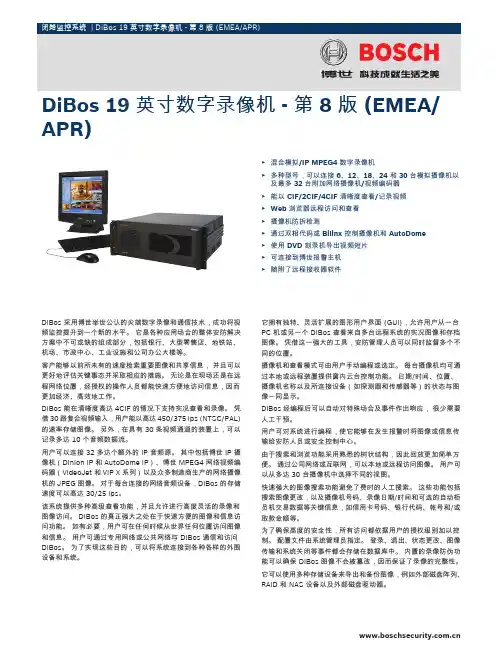
DiBos 采用博世举世公认的尖端数字录像和通信技术,成功将视频监控提升到一个新的水平。
它是各种应用场合的整体安防解决方案中不可或缺的组成部分,包括银行、大型零售店、地铁站、机场、市政中心、工业设施和公司办公大楼等。
客户能够以前所未有的速度检索重要图像和共享信息,并且可以更好地评估关键事态并采取相应的措施。
无论是在现场还是在远程网络位置,经授权的操作人员都能快速方便地访问信息,因而更加经济、高效地工作。
DiBos 能在清晰度高达 4CIF 的情况下支持实况查看和录像。
凭借 30 路复合视频输入,用户能以高达 450/375 ips (NTSC/PAL)的速率存储图像。
另外,在具有 30 条视频通道的装置上,可以记录多达 10 个音频数据流。
用户可以连接 32 多达个额外的 IP 音频源。
其中包括博世 IP 摄像机(Dinion IP 和 AutoDome IP)、博世 MPEG4 网络视频编码器(VideoJet 和 VIP X 系列)以及众多制造商生产的网络摄像机的 JPEG 图像。
对于每台连接的网络音频设备,DiBos 的存储速度可以高达 30/25 ips。
该系统提供多种高级查看功能,并且允许进行高度灵活的录像和图像访问。
DiBos 的真正强大之处在于快速方便的图像和信息访问功能。
如有必要,用户可在任何时候从世界任何位置访问图像和信息。
用户可通过专用网络或公共网络与 DiBos 通信和访问DiBos。
为了实现这些目的,可以将系统连接到各种各样的外围设备和系统。
它拥有独特、灵活扩展的图形用户界面 (GUI),允许用户从一台PC 机或另一个 DiBos 查看来自多台远程系统的实况图像和存档图像。
凭借这一强大的工具,安防管理人员可以同时监督多个不同的位置。
摄像机和查看模式可由用户手动编程或选定。
每台摄像机均可通过本地或远程装置提供窗内云台控制功能。
日期/时间、位置、摄像机名称以及所连接设备(如探测器和传感器等)的状态与图像一同显示。
日本TOTA托塔监控系列产品:摄像机、矩阵、硬盘录像机、监视器、画画面处理器等TOTA450III/TOTA500III/TOTA520III/TOTA600/TOTA002L银行柜员制专用摄像机TOTA500III日本TOTA托塔监控系列产品:银行柜员制专用摄像机、画面处理器等TOTA450III/TOTA500III/TOTA-MV94/99/96PTOTA银行柜员制专用摄像机TOTA420 TOTA-200PL TOTA-400III TOTA-500DN TOTA-500IIITOTA-560III TOTA-480AF TOTA-002L TOTA-380 TOTA-450IIITOTA-600III TOTA-480NDTOTA智能快球TOTA–180PH TOTA–220PH TOTA–180POH TOTA–220POH TOTA–180PONHTOTA–270PONH TOTA–160PM TOTA–160POM TOTA–36PM TOTA–108PMTOTA画面处理器TOTA-MV94P TOTA-MV96P TOTA-MV99PTOTA监视器TOTA-140C TOTA-170B TOTA-140B TOTA-210C日本TOTA一、彩色系列:序号型号规格单价1 TOTA-500Ш0.2Lux,510线分辨率,AC24或DC12V自动转换32762 TOTA-400Ш0.4Lux,420线分辨率,AC24或DC12V自动转换21603 TOTA-420 1.0Lux,480线分辨率,半球型(3.5、4、8、12镜头)25204 TOTA-500DN 黑白照度0.01Lux(可接红外灯),彩色照度1Lux,DC12V 33605 TOTA-560Ⅲ0.1LUX,510线分辨率,具有DVR硬盘压缩技术,超强背光补偿功能 43206 TOTA-200PL 1/3″,420线1LUX,针孔型彩色单板摄像机1680二、一体机系列:序号型号配置单价1 TOTA-480AF 480线,16倍变焦镜头,1.2Lux照度,一体化彩色摄像机46802 TOTA-480ND 480线,16倍变焦镜头,白天彩色,晚上黑白,一体化摄像机6480三、智能化快球序号型号配置单价1 TOTA-100 高速球控制键盘,RS480通讯口,最多可控制32台高速球,输入电压DC12V2 TOTA-180PH 18倍变焦镜头,480线彩色摄像机,1LUX,360度无限位旋转,250°/秒转速3 TOTA-220PH 22倍变焦镜头,其它同上172804 TOTA-180POH 18倍变焦,室外一体化高速球型摄像机,其它同上152885 TOTA-220POH 22倍变焦镜头,室外型一体化高速球型摄像机,其它同上186246 TOTA-180PONH 18倍变焦镜头,白天彩色,晚上黑白自动转换摄像机,室外型高速球型摄像机7 TOTA-270PONH 27倍变焦镜头,其它同上18960黑白系列:序号型号规格单价1 TOTA-600Ш600线,0.05Lux高分辨黑白摄像机,AC24V/DC12V 26002 TOTA-450Ш450线,0.01Lux黑白摄像机,AC24V/DC12V 13003 TOTA-380D 380线,0.05Lux黑白半球型摄像机,DC12V 8604 TOTA-002L 570线,0.0003Lux黑白超低照度摄像机,DC12V 24005 TOTA-380 380线,0.05LUX照度黑白摄像机,DC12V(经济型)8506 TOTA-101A 1/3″,420线,0.01LUX照度,针孔型黑白单板摄像机960。
网络数字录像机(NVR )用户手册- 1 -前 言注意事项:欢迎您使用本公司网络数字录像机(NVR)产品,为保障你安全稳定的使用,请务必仔细阅读本使用手册,下面是关于产品的正确使用方法以及预防危险、防止财产受到损失等内容,使用时请务必遵守。
1.安装环境:请在0℃-50℃的温度环境下放置和使用本产品;设备安装与使用时应水平放置,尽量避免倾斜或倒置;避免放置或安装在高温、潮湿、有灰尘或煤烟的场所。
设备不应遭受水滴或水溅,设备上不应放置诸如花瓶一类的装满液体的物品,勿将其他设备放置于本产品上面。
为保证设备的正常散热,在设备中设计装有散热风扇,应尽量将设备安装在通风良好的环境;录像机安装时,其后部应距离其它设备或墙壁6CM 以上,便于散热;在多雷地区使用时,请安装避雷装置,以避免雷击引起的主机故障或硬件烧坏。
2.注意事项:不要用湿手或潮湿的物品接触电源开关与网络数字录像机,以免触电;安装完主机一定确保主机以及机箱接地,以避免视频、音频信号受到干扰,以及避免网络数字录像机被静电损坏;请确保网络数字录像机供电电源电压的稳定,尽量使用电压值稳定,波纹干扰较小的电源输入,不要采用直接断开总开关的方式关闭网络数字录像机; 勿将液体或金属溅落在录像机上,以免造成机器内部短路或失火;设备不包括硬盘 ,在使用前需正确安装硬盘,否则将不能进行录放像操作; 主板上的灰尘在受潮后会引起短路,为了使网络数字录像机能长期正常工作,应该定期用刷子对主板、接插件、机箱及机箱风扇等进行除尘;网络数字录像机关机时,不要直接关闭电源开关,应使用面板上的关机按钮,使网络数字录像机自动关掉电源,以免损坏硬盘;主机系统支持硬盘的格式化功能,如果硬盘已经使用过,请注意是否为FAT32格式的,本嵌入式网络数字录像机只支持FAT32格式,否则将有出错的隐患,; 请勿带电打开机器;为保证录像数据的完整性,发现坏硬盘请及时进行更换(日志中有关于磁盘错误的记录)。
平安威视嵌入式硬盘录像机PA-9216产品功能特点基本功能采用嵌入式Linux操作系统;采用标准H.264压缩算法,压缩比高,且处理非常灵活;支持4/8/16/24路视频输入;支持8/4路720P 或4/2路1080P高清IPC接入输入;1路VGA视频输出,同时支持16路环通输出,支持HDMI,VGA,CVBS,SPOT输出;支持4/8/16路音频输入,1路BNC音频输出;支持RS-485接口,可以控制云台,可扩展多种解码协议;RS-232接口,设备升级和扩展应用;支持16个通道录像同时回放;支持语音对讲(同时支持有源BNC接口,无源3.55mm接口);内置WEB Server方便远程控制管理;支持手机预览(WinCE,Symbian,iPhone);支持多种DDNS(花生壳,3322,dyndns);支持TB级大容量硬盘;支持鼠标局部区域拖动数字放大;支持鼠标高速云台控制;多级用户权限管理,保证系统安全。
压缩处理功能视频压缩采用H.264压缩算法,可实时每秒25帧D1分辨率的独立硬件压缩,部分型号实时每秒25帧CIF 分辨率的独立硬件压缩;支持变码率,支持变帧率,在设定视频图像质量的同时,也可限定视频图像的压缩码流;支持4/8/16/24路视音频信号,视音频信号由独立硬件实时压缩,声音与图像保持同步;支持1080P(1920*1080)、720P(1280*720)、D1(704*576)、、HD1(704*288)CIF(352*288)、QCIF (176*144)分辨率;支持OSD,日期时间可以设置,支持多区域遮挡。
存储备份功能内置1/2/4/8个SATA硬盘接口,每接口可挂接TB级硬盘;通过USB接口(如普通U盘及移动硬盘等)进行备份;客户端电脑可通过网络下载硬盘上的文件进行备份;硬盘工作管理采用非工作盘休眠处理,利于散热及降低功耗,延长硬盘寿命;硬盘文件包括覆盖式循环记录和非循环记录;存储数据采用专用格式,无法篡改数据,保证数据安全。
变电站视频监控系统安装及测试工艺规范EX2007-12-20爱科赛科技有限公司变电站视频监控系统安装及测试工艺规范资料版本:EVS1BOM编码:20071220深圳爱科赛科技有限公司为客户提供全方位的技术支持,用户可与就近的深圳爱科赛科技有限公司办事处或客户服务中心联系,也可直接与公司总部联系。
深圳爱科赛科技有限公司地址:深圳市南山区蛇口工业大道27号北科创业大厦909邮编:518067公司网址:客户服务热线:*************E-mail:excesys@目录第一章总则 (4)1.1 目的 (4)1.2 适用范围 (4)1.3 引用文件 (4)1.4 现场安装及施工原则 (5)1.5 施工前的准备 (5)第二章EVS图像监控系统硬件安装 (6)第三章监控中心安装工艺规范 (24)3.1 监控中心的安装原则 (24)3.2 监控中心安装环境要求 (24)3.3 监控中心设备的安放规则 (25)3.4 监控中心各种设备的安装 (27)3.4.1 计算机的安装 (27)3.4.2集线器的安装 (27)3.5系统监控中心的供电系统 (29)3.5.1 概述 (29)3.5.2 逆变器供电系统 (29)3.5.3 监控中心供电系统的总体要求 (29)第四章现场布线接线 (31)4.1 布线原则 (31)4.2配线说明 (32)4.3穿管说明 (32)第五章系统接地与防雷规范 (33)5.1 系统接地原则 (33)5.2 工程防雷接地参考办法 (35)第六章工程施工其它说明 (38)6.1系统检查 (38)6.2 特殊机房环境的安装施工 (38)第七章工程附件及工具 (39)7.1 工程附件实物及用途 (39)7.2 特殊工具使用范例 (45)第八章标签和标牌 (48)第九章所需材料及附件清单 (54)第十章立竿参考图纸 (56)第一章总则1.1 目的完善现场安装工艺的规范性及现场施工指导准确性,经修订提出此工艺规范。