挪威海德罗公司油气井完整性
- 格式:pps
- 大小:559.00 KB
- 文档页数:23
国外海对海定向钻工程案例海对海定向钻工程是一种在海洋环境下进行的钻井作业,它的目的是在海底或海洋地壳中进行钻井,并获得地下资源。
这种工程在国外被广泛应用于石油和天然气勘探与开发领域。
下面将介绍几个国外的海对海定向钻工程案例,以便更好地了解这项技术的应用和成就。
1. 布尔港海对海定向钻工程(布尔港,墨西哥)布尔港位于墨西哥湾,是墨西哥重要的石油生产基地之一。
为了开发墨西哥湾的海底油气资源,墨西哥国家石油公司(PEMEX)进行了一项海对海定向钻工程。
该工程采用了先进的定向钻井技术,成功钻取了海底油气储层,为墨西哥的能源开发做出了重要贡献。
2. 北海海对海定向钻工程(北海,挪威)北海是全球著名的油气勘探和开发区域,拥有丰富的石油和天然气资源。
挪威石油公司(Equinor)在北海进行了多项海对海定向钻工程。
其中,利用定向钻井技术成功钻取的乌斯特雷姆油田是挪威最大的海底油气田之一。
该油田的开发为挪威经济做出了重要贡献。
3. 加尔夫海对海定向钻工程(加尔夫,美国)加尔夫位于美国境内的墨西哥湾沿岸,是美国重要的海上石油产区。
美国能源公司在加尔夫进行了一项海对海定向钻工程,利用定向钻井技术成功钻取了海底油气储层。
这项工程为美国能源独立和能源安全做出了重要贡献。
4. 卡夫特海对海定向钻工程(卡夫特,巴西)卡夫特位于巴西沿海的圣保罗州,是巴西重要的石油产区。
巴西国家石油公司(Petrobras)在卡夫特进行了一项海对海定向钻工程,利用定向钻井技术成功钻取了海底油田。
这项工程为巴西的能源产业发展提供了强有力的支持。
5. 西非海对海定向钻工程(西非)西非地区拥有丰富的石油和天然气资源,因此海对海定向钻工程在该地区得到了广泛应用。
尼日利亚、安哥拉等国家的石油公司在西非海域进行了多项海对海定向钻工程,成功钻取了丰富的油气储量。
这些工程为西非地区的经济发展和能源安全做出了重要贡献。
综上所述,国外海对海定向钻工程在石油和天然气勘探与开发领域发挥了重要作用。
基于安全屏障的井完整性问题分析方法何英明;刘书杰;武治强;耿亚楠;冯桓榰;范志利【摘要】海洋石油钻完井作业风险高,极易发生井漏、井喷等井完整性事故.在役生产井生产年限越来越长,高温高压气井越来越多,环空带压问题日益突出.为了有效预防井完整性问题,提出基于安全屏障的井完整性问题分析模型,采用安全屏障、蝴蝶结、故障树与"人机物环法"5要素分析相结合的方法,分析事故发生及处理过程.%Offshore oil drilling and completion has high risk, easily occuring accidents of lost circulation, blowout and other well integrity problem. The production well age becomes longer and longer,and more HPHT wells bring more sustained casing pressure(SCP) problems. In order to effectively prevent and systematically analyze the cau-ses and treatment of the well integrity problem,a model of well integrity problem analysis based on safety barrier is proposed. Combined with safety barrier,bow-tie,fault tree and"people,machine,material,environment,regu-lation"five element analysis,this paper analyzes accident occurrence and treatment process.【期刊名称】《重庆科技学院学报(自然科学版)》【年(卷),期】2018(020)002【总页数】5页(P28-31,53)【关键词】安全屏障;井完整性;故障树;蝴蝶结【作者】何英明;刘书杰;武治强;耿亚楠;冯桓榰;范志利【作者单位】中海油研究总院,北京100028;中海油研究总院,北京100028;中海油研究总院,北京100028;中海油研究总院,北京100028;中海油研究总院,北京100028;中海油研究总院,北京100028【正文语种】中文【中图分类】TE21井完整性管理是指综合应用管理及技术措施,以降低地层流体发生非控制泄漏风险,贯穿整个井的生命周期。
挪威国油采用永久油藏监测技术增加石油产量
挪威国油采用永久油藏监测技术增加石油产量
2012-12-20 13:54:56 商务部网站微博评论浏览次数:23
字号:T|T
挪威国家石油公司(Stateoil)及其合作伙伴计划在北海的Snorre和Grane油田采用新的海上石油震动勘测技术(seismic tools)——永久油藏监测技术(permanent reservoir monitoring PRM)。
据预测,这项技术将帮助两个油田增加3000万桶石油产量。
国家石油公司有关负责人介绍,PRM技术能提供更及时和准确的海底油藏变化图像,将有助于提高采油率(recovery rate)以增加石油产量。
目前,国家石油公司在挪威大陆架的石油采油率是50%(世界平均水平是35%)。
按现有石油价格计算,每提高1%的采油率将带来3000亿挪威克朗(约合3270亿人民币)的收入。
传统的震动勘探技术是使用安装在轮船上的拖拽电缆传送声纳信号,而PRM技术则是把电缆嵌入到海底永久的设施内。
国家石油公司将在约240平方公里的海底铺设总长约700公里的电缆,这也是该公司第一次应用永久设备。
据悉,电缆将由美国公司Geospace Technologies提供,合用总价值约9亿挪威克朗(约合9.8亿人民币)。
安装工作分别由两家挪威公司Deepocea和Reef Subsea实施。
深水油气开发的海底工厂作者:马巍巍朱启龙来源:《石油知识》 2017年第2期从2014年下半年开始,国际油价的断崖式下跌给全球石油工业带来了沉重的打击,除了出售油气资产、削减投资、裁员降薪等措施外,各大石油公司也不约而同地采取了以科技创新推进公司降本增效的相关举措。
就开发成本较高的深海油气资源而言,追求更经济高效的新技术成为跨越开发屏障的必由之路,“海底工厂”这一新生事物也在此时应运而生。
初识“海底工厂”挪威国家石油公司是“海底工厂”这一新概念的提出者,也是海洋油气开发海底化的先驱,其进行的项目涵盖了海底开发的所有主要类型。
“海底工厂”是利用水下设备对从地层产出的流体在海底进行分离处理,以提高油气最终采收率,减少海面生产处理设施的投入,减少对环境产生的影响,从而实现海洋油气经济高效开发。
它是一个集油气水三相分离技术、水下增压技术、处理后的原油存储海底以及产出处理后进行回注于一体的“水下油气处理厂”。
从某种意义上讲,“海底工厂”可以看做是传统的水下生产系统的技术升级版。
相较于传统的水下生产系统,“海底工厂”有4项关键技术的突破,分别是海底增压系统、海底气体压缩系统、海底分离与产出水回注系统、海底输配电系统。
海底增压系统是海底工厂的核心,可将海底采出来的油气举升至海上平台;海底气体压缩系统是实现挖潜剩余油气资源、提高气藏最终采收率的关键;海底分离系统可在海底实现油、气、水的分离;海底输配电系统的高可靠性对于未来海底工厂的成功应用具有非常关键的作用。
“海底工厂”的分类“海底工厂”将成为深水、北极和离海岸线更远的油气田开发的有效手段。
为了能够适用于多种类型的海上油气田,挪威国家石油公司2013年将海底工厂分为3类:褐色油田海底工厂,绿色油田海底工厂和面向市场的海底工厂。
褐色油田海底工厂旨在提高老油田的采收率、维持或提高产量,海底增压与压缩是最为关键的技术。
绿色油田海底工厂旨在实现海洋油气开发向更远、更深和更冷领域拓展。
173完整性管理技术是油气田安全生产管理发展的新方向,主要包括井下和地面集输系统两大方面。
早在20世纪70年代,国外就已经开始发展油气田管道完整性评价和管理技术[1],逐渐形成了一套较为完整的管理体系。
我国油气管道的完整性管理开始于上世纪九十年代末,近年发布了两项相关行业标准,并应用于输油、输气管道[2,3]。
本文主要对国外油气井完整性管理发展现状和现有的相关标准、软件及应用情况、生产阶段的完整性管理以及国内油气井完整性管理发展现状进行了概述和总结。
1 油气井完整性的概念及相关标准1.1 概念“油气井完整性”的概念来源于国外,目前有两个较为权威的正式文件API RP 90[4] 和NORSOK STANDARD D-010[5]对油气井完整性进行了一致定义:“在油气井整个生命周期中应用各种技术、操作及管理手段来降低地层流体失控流动带来的风险”,这也是业内所接受的对油气井完整性的定义。
1.2 相关标准API RP 90是针对“离岸井的环形套管压力管理”的一个推荐做法,而NORSOK STANDARD D-010则是针对油气井从钻井、完井、试井到生产等阶段的完整性管理推荐的最佳做法,这一标准是目前仅有的针对油气井完整性的专业标准。
NORSOK STANDARD D-010标准以目前国际上相关通用的ISO、API和NORSOK体系标准等为基础,同时增加了一些必要条款以满足各类油气井完整性管理的需要。
该标准的主题是油气井的完整性,提出了在油气井设计、井下作业、生产操作的相关计划和施工过程中油气井完整性的最低要求,以及实施操作过程中的指导原则。
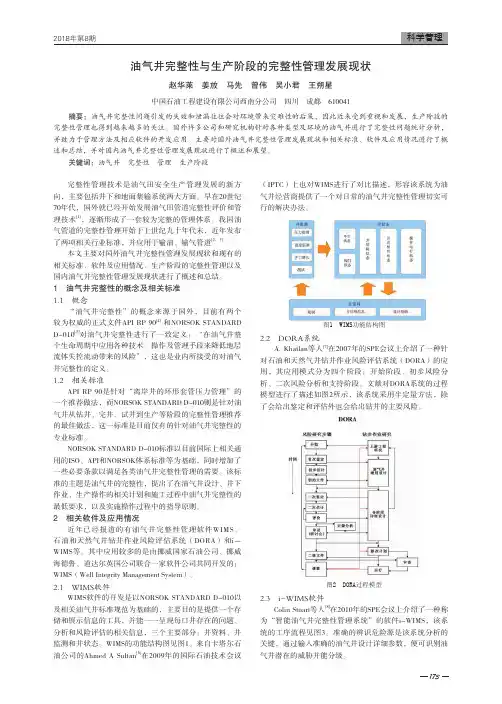
2 相关软件及应用情况近年已经报道的有油气井完整性管理软件WIMS、石油和天然气井钻井作业风险评估系统(DORA)和i-WIMS等。
其中应用较多的是由挪威国家石油公司、挪威海德鲁、道达尔英国公司联合一家软件公司共同开发的:WIMS(Well Integrity Management System)。
雪佛龙获得挪威海勘探权
佚名
【期刊名称】《经济导报:石油天然气》
【年(卷),期】2011(000)002
【摘要】在挪威第21轮石油业务执照招标会上,欧洲雪佛龙公司成功竞得四个区块的勘探权。
这四个板块位于挪威海的外voring盆地,博得海岸以西约335英里(540公里)、水下6824英尺(2080米)的区域。
【总页数】1页(P8-8)
【正文语种】中文
【中图分类】F433.362
【相关文献】
1.威海市获得专利案件处理权 [J],
2.五矿集团公司获得东太平洋矿区专属勘探权和优先开采权 [J],
3.中国获得西太平洋富钴结壳矿区专属勘探权 [J], 中央政府门户网站
4.我国获得西太平洋富钴结壳矿区专属勘探权 [J],
5.W2016085美国获得库克群岛稀土的专属勘探开采权 [J],
因版权原因,仅展示原文概要,查看原文内容请购买。
迪那2井完整性评价及风险分析景宏涛;彭建云;张宝;曾努;宋静波;马亚琴;王珊【期刊名称】《石化技术》【年(卷),期】2015(000)001【摘要】迪那2井是塔里木盆地的一口高压气井,该井试油结束后发现套压异常,经测试证实井筒完整性存在问题。
按照油气井完整性管理理念,对该井进行异常情况分析和风险识别,并根据NORSOK井筒完整性指导意见,对本井进行一级屏障、二级屏障的划分及完整性评价,评价结果认为该井一级屏障失效,二级屏障不合格,井筒完整性类别为红色,存在较大安全风险,应采取维修措施或封井。
该井的分析评估流程及方法,对同类高压气井的分析评估具有借鉴意义。
【总页数】2页(P15-16)【作者】景宏涛;彭建云;张宝;曾努;宋静波;马亚琴;王珊【作者单位】塔里木油田公司新疆库尔勒 841000;塔里木油田公司新疆库尔勒841000;塔里木油田公司新疆库尔勒 841000;塔里木油田公司新疆库尔勒841000;塔里木油田公司新疆库尔勒 841000;塔里木油田公司新疆库尔勒841000;塔里木油田公司新疆库尔勒 841000【正文语种】中文【相关文献】1.井地地震CT在岩画山体完整性评价中的应用 [J], 刘黎;梁红波;滑玉琎;刘玉;关文政;金彦2.地面直读试井工艺在迪那202井的应用浅析 [J], 马红英;秦世勇;冯广庆3.气田水回注井井身结构完整性评价方法初探 [J], 况雪梅;张凤琼;李大鹏;卢邹;谢佳君;何军4.电缆地面直读试井工艺在迪那202井的应用浅析 [J], 何银达;马红英;秦世勇;冯广庆5.基于权重分析法的海洋弃置井井筒完整性评价方法建立 [J], 周松民;李军伟;李瑾;李军;连威因版权原因,仅展示原文概要,查看原文内容请购买。
2020年10月第36卷第10期石油工业技术监督Technology Supervision in Petroleum IndustryOct.2020Vol.36No.102021年4月第37卷第4期Apr.2021 Vol.37No.4海上油田M井井筒完整性失效分析及处理方法柳海啸1,徐振东1,李文涛1,刘海龙2,乔中山21.中海石油(中国)有限公司蓬勃作业公司(天津300459)2.中海石油(中国)有限公司天津分公司(天津300459)摘要随着油田开发时间的增长,油水井井筒完整性问题越来越突出,环空带压问题越来越普遍,对安全生产造成了严重的威胁。
介绍了海上油田M井井筒完整性管理及实践方法,对问题井进行定量分析,针对油井B环空带压问题,创新采用罐装泵系统,重新构建两道完整的井下屏障,以较低的成本满足井筒完整性管理要求,恢复油井正常生产,达到良好的经济效益。
关键词井筒完整性;环空带压;井筒屏障;罐装泵Wellbore Integrity Failure Analysis and Handling Method of Well M in an Offshore Oilfield Liu Haixiao1,Xu Zhendong1,Li Wentao1,Liu Hailong2,Qiao Zhongshan21.Pengbo Operation Company,CNOOC(China)Co.,Ltd.(Tianjin300459,China)2.Tianjin Branch,CNOOC(China)Co.,Ltd.(Tianjin300459,China)Abstract With the extension of oilfield development time,the problem of wellbore integrity of oil and water wells is becoming more and more prominent,and the problem of annulus pressure is becoming more and more common,which poses a serious threat to the safety of production.This paper mainly introduces the wellbore integrity management and practice means of M well in an offshore oilfield,and makes quantitative analysis on the problem wells.Aiming at the problem of annulus pressure in well B,two complete downhole barriers are reconstructed by using innovatively canned pump system,and the requirements of wellbore integrity management are met with low cost,the normal production of oil wells is restored,and good economic benefits are achieved.Key words wellbore integrity;annulus pressure;wellbore barrier;canned pump柳海啸,徐振东,李文涛,等.海上油田M井井筒完整性失效分析及处理方法[J].石油工业技术监督,2021,37(4):36-39.Liu Haixiao,Xu Zhendong,Li Wentao,et al.Wellbore integrity failure analysis and handling method of well M in an offshore oil⁃field[J].Technology Supervision in Petroleum Industry,2021,37(4):36-39.0引言在石油的开采开发过程中,生产安全十分重要,一旦出现不可控制的安全事故,会给人员、环境及财产带来重大的损失。
挪威法规对钻井平台的要求WANG Dong-shi【摘要】介绍了挪威大陆架石油活动的法规框架.从一般要求、设计、设施等方面探讨了该系列法规对海洋石油钻井平台的要求,并归纳了部分具体要求.以期能够对在挪威大陆架从事石油活动的钻井平台做符合性检查,并为取得AoC(法律法规符合性证明)提供帮助.【期刊名称】《船舶设计通讯》【年(卷),期】2018(000)002【总页数】5页(P33-37)【关键词】挪威法规;钻井平台;符合性证明【作者】WANG Dong-shi【作者单位】【正文语种】中文【中图分类】U674.38+10 前言石油工业是挪威国民经济的重要支柱产业,且发展处于世界领先水平,海洋石油工业活动的制度体系健全。
挪威大陆架海域的海洋气候环境恶劣,随着海上油田的不断发展,从其国家层面对海洋石油钻井行业的要求也在不断修订和完善,形成了一整套有关石油活动的法规体系。
该法规体系具有强制性和独特性。
强制性是指在挪威大陆架从事石油活动的所有单位必须遵守。
独特性则是具体要求非常细致且有别于或高于世界范围内广泛应用的规范和标准。
本文对挪威大陆架石油活动的专有法规要求进行了介绍,以期为欲取得挪威管理当局符合性证明的海洋石油钻井平台的设计和建造提供参考。
1 挪威大陆架海洋石油活动专有法规挪威政府设有石油工业的专门管理机构——挪威石油安全管理局(PSA)。
PSA颁布了适用于挪威境内石油活动的框架性法规《石油活动健康、环境、安全法》。
该法规分为五部分:1)框架法规:《石油工业健康、环保与安全法规》;2)管理法规:《石油工业管理法规》;3)信息责任法规:《石油工业材料与信息法规》;4)设施法规:《石油工业设备的设计、配置法规》;5)行为法规:《石油工业行为法规》。
2007年1月1日始,所有在挪威境内从事石油勘探活动的钻井平台、生活支持平台、浮式开采/存储油轮(FPSO)、浮式钻井/开采/存储/卸载多功能平台(FDPSO)、修井船舶等都必须保证其技术状况、管理系统、组织机构满足《石油活动健康、环境、安全法》的要求。
Well Integrity within Norsk HydroObjective●Develop a consistent procedure formanagement of annular leaks●Risk based approach●Routines for early detection and how tohandle the leaks●Procedure made in collaboration betweenNH, Exprosoft and Kåre Kopren(PTG)●Key items in the procedure:●Include detection, diagnosis, assessment and responses to well annular leaks●No increase in installation risk (QRA modelling)●Specific risk reduction measures●Variations in risk level (subsea vs. topside, gas vs. oil, etc.)●Applicable to all well types operated by Norsk Hydro●In compliance with regulations and standardsPrinciples●Overview of well data and limitations shall follow the well throughout the lifetime●All leaks shall trigger an internal deviation (synergi) –verification in B&B●Well data shall be updated when a leak is detected●Checkout of integrity of next casing●Test program to identify leak above or below BSV, surface pressure after stabilizing of pressure, leak rate●Update of well risk level, based on Wellmaster database●Update of operational proceduresWOCSTo The Cutting's Disposal SystemAMV AVV ACVBMVAWVXOV SIV SITPMBSProductionScale Inhibitor MethanolFlow -line connectorPCVPWV SCVPMVPSliding sleeveFlow control valvesRetrievabl e isolation packerSide mounted gunsGas cap gas lift screen and gas lift valvePressure gauge DHSVRetrievableproduction packerClean out valveScreen with ECP andradioactive tracerStatus procedure for management of well annular leaks●Procedure is finishedRemains:●Implementation●Training of offshore personnel to detect leakages + diagnostic work● A pilot course has been held in april.●Standard course package will be developed based on the experiencefrom the pilot course●All personell involved in detection and diagnostic work offshore andonshore will be invitedHistorical Norsk Hydro downhole annulus well integrity (WI) issues by fieldNote: Based on Norsk Hydro WellMaster phase V data (Snorre and Visund currently Statoil), last major database update April 2004Figure shows “Cumulative #Annulus WI Issues / Cumulative #Completions” by YearField 1995199619971998199920002001200220032004BORG 0.0 %0.0 %0.0 %0.0 %0.0 %0.0 %BRAGE0.0 %0.0 %7.4 %9.7 %17.6 %60.4 %57.9 %54.7 %60.0 %59.1 %FRAM VEST 0.0 %0.0 %0.0 %GRANE 0.0 %0.0 %12.5 %NJORD0.0 %0.0 %16.7 %12.5 %35.3 %44.4 %47.4 %47.4 %OSEBERG B 2.9 % 2.6 % 2.3 % 2.0 % 1.9 % 1.8 % 6.6 %8.1 %7.5 %7.4 %OSEBERG C 0.0 %0.0 %0.0 % 3.0 % 6.1 % 6.1 % 5.4 % 5.0 %5.0 % 5.0 %OSEBERG S 豏0.0 %0.0 %9.1 %14.3 %11.1 %10.5 %OSEBERG VEST 0.0 %0.0 %0.0 %0.0 %0.0 %0.0 %0.0 %0.0 %0.0 %OSEBERG 豐T 75.0 %27.3 %20.0 %21.1 %25.0 %25.0 %SNORRE 0.0 %0.0 %1.6 %1.5 %2.6 %3.5 %7.5 %8.1 %8.1 %8.1 %SNORRE B 0.0 %0.0 %0.0 %0.0 %TOGP 0.0 %0.0 %0.0 %0.0 %0.0 %0.0 %0.0 %TORDIS 0.0 %14.3 %14.3 %12.5 %11.1 %11.1 %10.0 %10.0 %10.0 %10.0 %TWOP 0.0 %0.0 %0.0 %0.0 % 4.2 %8.0 %7.7 %39.3 %39.3 %37.9 %VARG 0.0 %0.0 %0.0 %0.0 %0.0 %0.0 %0.0 %VIGDIS 0.0 %0.0 %0.0 %0.0 %0.0 %0.0 %0.0 %0.0 %0.0 %VISUND 0.0 %0.0 %0.0 %0.0 %0.0 %10.0 %10.0 %10.0 %Total0.7 %1.1 %2.5 %3.0 % 6.3 %12.4 %14.6 %16.7 %16.9 %17.0 %0.0 %5.0 %10.0 %15.0 %20.0 %1995199619971998199920002001200220032004Task Force : Well leaks -Root Cause AnalysisJ. Abdollahi SintefBest practice ISO test Wear testingDope-free connectionTommy LangnesOCTGWear testing Geir Ove HaugenDrill pipeDiagnosis Packer design Safety factors Best practice Course DatabaseBarrier test procedureHilde B. Haga Completion designWear testing Material selection Tore R Andersen Material technologyDiagnosis Course ProceduresThorvald Jakbsen Prod. technologyInge M. CarlsenSintefReference group : Bj ørn Engedal (leader), Nils Romslo, Geir Slora, Eli Tenold, Bjarne Syrstad, Torbj ørn Øvreb ø, Siamos AnastasiosOngoing work: Well Integrity Management System (WIMS)●New database to be developed until 2007●JIP managed by Exprosoft with Hydro, Statoil and Total asparticipants.● A development based on the procedure for management of wellannular leaks●Purpose:● A uniform and structured approach for handling of well integrity duringthe lifetime of a well.●All information available through one system● A clear indication of the well barrier status at all timesWell Integrity Management System (WIMS)●WellMaster software used as a basis –additional applications to bedeveloped●Important functionalities:●Visualising the well barriers and well barrier elements (WBE) throughuse of barrier diagrams and barrier sketches●Identify the functions and and requirements that the well and eachWBE should fulfil●Present the status/condition of each WBE (leak, erosion, etc.)●Keep record of performed tests and results of tests●Keep record of diagnosis results when deviations are identified●Keep record of changes in well integrity and resulting corrective actions●Overview of well risk status●Structured / uniform approach to analyze and evaluate riskRisk based procedure for management of well annular leaksRationale for risk based approach●Reflect variations in actual well risk level●Subsea, topside●Gas, oil, water●Etc.●In principle no tubing and casing leaks accepted by the PSA●”to be on the safe side” –leak(s) will affect the operational risk ina negative wayHowever;●Regulations and NORSOK D-010 open for risk assessment●Departure normally granted by submission of supporting riskanalysis results●Must incorporate principle of ”risk reduction” –risk should not besignificantly higher as a result of the deviationProcedure outline●Procedure split in three main tasks(guidelines):1. Detection and diagnosis2. Evaluation3. Implementation and follow-up●Main results●Extensive diagnosis part●Risk assessment method–Specific risk acceptance criteria–Extensive use of quantitative riskanalysis (fault tree analysis withWellMaster data as input)–Specific risk reduction measures●Documentation of processWell normaloperationCompare AcceptancecriteriaAnnuluspressurelimitsDiagnosisRisk and responseevaluationImplementation andfollow-upTask 1; Detection and diagnosis ●Collection of basic well data (preparatory)●Well schematic, P-tests/FIT/LOT, annuluscapabilities (as well barrier), annular volumes,fluid densities, etc.●When is it needed to assess if there is a leak?●Establish Max operational A-annulus pressure(MOASP) = default bleed off alarm limit●Establish pressure domain for initiation ofdiagnosis activities●“External factors” diagnosis●Abnormal pressure readings may not beattributed to downhole failure/degradation●“Internal factors” diagnosis”●The potential leak rate to the wellheadsurroundings (if blowout through leak path)●Amount of hydrocarbon influx to the annulus●Leak location (depth and relative to well barriers)●Leak failure cause (deterioration/escalationpotential)●Leak directionsWell normaloperationCompare AnnuluspressurelimitsDiagnosis Well designMonitoringLeak location(P vs. TVD)and leak rateestimation toolsprovidedTask 2; Risk assessment and response evaluationAcceptance criteria Risk and responseevaluation Implementation andfollow-up●Risk assessment stepwise covers several risk factors● A risk status code (RSC) is assigned to the well ineach step●Most severe RSC determines the RSC for the well●The well RSC determines a set of actions/risk reducingmeasures to be implemented -Each risk factor have specificrisk factor acceptance criteria●Risk factor acceptance criteria basis:●No risk increase on installation level (as modelled in QRA)●Quantitative analysis performed for a representative ”library” of well types inorder to measure relative increase in leakage risk and effect of risk reducing measures●Rule based/deterministic acceptance criteria (based on industry practice)–Minimum two well barriers–No leak to surroundings–Allowable hydrocarbon (HC) storage in annuli–Risk of escalation/further detoriation–Change in well kill opportunityTask 2; Well risk status code overviewRSC Well RSC description Well risk acceptance A No downhole leak AcceptableB Degraded well.Small increase in risk (none or only relatedto HC in annuli)Acceptable.Risk can be controlledC Degraded well.High risk increase (e.g. P A above MOASPduring normal operation)Acceptable only if risk factors can be controlled (e.g, reduce P A to below MOASP during normal operation)D Dual barrier philosophy not fulfilled / wellbarriers severely degraded / leak tosurroundingsNot acceptableRA step 1; Risk factor = Look at well barrier leak rate consequences●Leak rate acceptance criteria based on leak sizes reflected in●QRA’s on installation level●API 14B leak rate criteria (SCSSV)●Norsk Hydro risk matrix●Different leak rate acceptance criteria for●Non-natural flowing or Non-hydrocarbon flowing wells vs. Hydrocarbon flowing wellsCriteriaRSC Well barrier leak rate lower than acceptance criterion (not considered a failed barrier)B Leak (any size) to a volume not enveloped by qualified well barriersDRA step 2; Risk factor = Relative change in blowout probability –example●Risk status codes based on calculated blowout probability and risk reduction potential assigned to●Surface and subsea wells●Conventional wells (applies to production and injection wells) and gas lift wells●Informative calculations performed for multipurpose well, and gas lift well alternatives with combinations of deep set SCSSV, no SCASSV, annulus tail pipe SCSSV.Interm. Csg. BarrierWell barrier leak rates greater than acceptance criterion (RAC Item no. 5)T/A leak below SCSSVT/A leak above SCSSVA/B leakT/A leak above SCSSV AND A/B leakConventional platform wellNo D C D D YesDCCCRA step 3; Risk factor = Look at well release risk (HC storage -single failure scenario)●Hydrocarbon storage criteria relates to:●For surface wells the quantity of hydrocarbons stored in the well annuli should not be greater than the typical mass of lift gas in the A-annulus above the SCASSV in a gas lift well OR alternatively the max recommended volume stored in other vessels on surface●For subsea wells the release quantity criterion is based on distance to permanent surface installations (rising gas plume) and environmental acceptance criteriaCriteriaRSC The hydrocarbon storage mass in the well annuli is, or may become, greater than the acceptance criterion ORWell annuli fluids are highly toxic (platform well)COtherwiseBRA step 4; Risk factor = Look at leakage cause (well functionality-degradation)●Further escalation that cannot be controlled should not be accepted●If further escalation/degradation of the well can be controlled by given risk reducing measures this can be acceptedCriteriaRSC Material corrosion or erosion is the (most likely) leak cause.D There is, or is a potential for, exposure of equipment toH2S/CO2 levels that are outside design/NACE specifications.ORThere is crossflow (unintended flow) in the well COtherwiseBRA step 5; Risk factor = Look at mechanical/ pressure loads (well functionality –loads/single failure scenario)●Maximum Operational A-annulus Surface Pressure (MOASP) is the limiting wellhead pressure that the A-annulus is deemed safe to be operated under for an extended period of time (years), e.g., for well production.–MOASP = Max known P-integrity of next outer functional annulus (from P-tests, LOT, FIT, recognised field formation fracture gradient data)●Checklist for MTP vs. MOASP provided●If A-annulus pressure can be controlled <= MOASP this can be acceptedCriteriaRSC The maximum potential A-annulus pressure -PA (MTP / A-annulus injection pressure) is greater than MOASP ORMechanical / Pressure loads causing burst/fracture/collapse is the (likely) leak cause COtherwiseBRA step 6; Risk factor = Look at wellkill/recoverability (well functionality –well kill /single failure scenario)If well kill procedures/preparations can be revised and be equally effective as the base case (well with no failure) this can be acceptedCriteriaRSC An additional single well barrier leak situation may affect the ability to efficiently kill the well with mud.C OtherwiseBResponse actions●The resulting Well RSC determines a set of mandatory (M) and alternative(S) remedial actions/risk reducing measures to be implemented●Remedial actions for each RSC based on●Norsk Hydro and industry best practice●The risk assessment (step 1 through 6)RSCABCD Response (illustrative example only)A B C D Revise alarm settings M M M M Increased monitoring M M Increased well barrier testing M S Make plans for well kill M M Immediate intervention to restore twowell barrier envelopes MSummary●Applicable to the well types Norsk Hydro operates●In compliance with regulations and standards for the upstreamsector of the oil industry●Guidelines and worksheets included for detection, diagnosis, andrisk assessment and response to well barrier leaks●Support tools and formulas for diagnosis included●Modular system. Easy to update risk factor acceptance criteria,include additional risk factors, revise risk reduction measures, etc.●Documentation of well “history”●”Library” of relative well leak probabilities -The well leak probabilityfor a wide variety of well types and leak locations are modelled for future referenceQuestions?。