UT-1208八口RS-485集线器(HUB)产品说明书
- 格式:pdf
- 大小:34.00 KB
- 文档页数:2
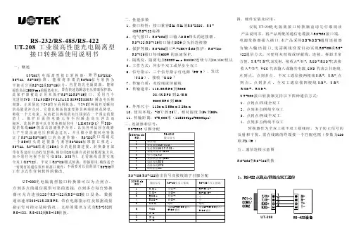
目录一.概述: (2)二.性能参数: (2)三.接线端子说明: (3)四.通讯波特率设置: (3)五.CHD-485HUB包装清单: (4)六.使用CHD-485HUB优点 (5)七.使用CHD-485HUB RS485网络集线器扩展网络 (5)一.概述:CHD-485HUB RS485网络集线器是专门为扩展RS485通信能力、延长通信距离以及便于组网而设计的,它是远距离控制设备一点对多点RS485网络最佳的扩展组网中继设备。
具有以下功能:●将标准RS232转换成4路独立的RS485,扩展RS485联接能力及设备数量,节省RS232-RS485转换器,同时也避免串口窃电所带来的不稳定性;(可直接与PC机串口联接)●把一路RS485输入线接入主路RS485,扩展成4路相互独立的RS485,提升RS485通信能力及增加联接设备数量、延长通信距离。
(方便树型结构组网)二.性能参数:※接口兼容EIA/TIA之RS232和RS485标准;※标准RS232转四路相互独立RS485或一路RS485扩展四路相互独立RS485,二者选其一;※四路输出之间的接地相互隔离,提高设备的抗干扰能力和通讯的稳定性;※通讯速率:4800/9600/19200/38400BPS 可通过拔档开关设定,出厂缺省为9600BPS;※通信格式:1起始位,8数据位,1停止位,无校验位,支持国家邮电总局YDN023-1996标准。
※宽范围供电:直流10~35V,功耗小于1瓦;※接口保护措施:三级防雷保护,过流保护(自复保险丝),+/-15KV ESD静电放电保护,瞬态过压600瓦保护(即浪涌抑制);※每路RS485最多可并挂32台联网设备;每路通讯距离最大为1200米;※工作电流:静态时为25mA;※使用环境:-20℃到70℃,相对湿度为5% 到 95%,产品采用100%防潮处理适合比较恶劣的环境工作;※外形尺寸:150mm x 100mm x 35mm※状态指示:“PWR”电源指示灯---供电正常该绿色指示灯亮;“LED”红色通讯指示灯---平时不亮,只有通讯正常收发数据时不停闪烁;(当哪一路输出发生短路时,该路输出的红色指示灯也不停闪烁,注意区别通讯正常与短路闪灯的状态)。
电源 上联口
8口集线器(HUB )使用说明书
◆8口集线器功能简介
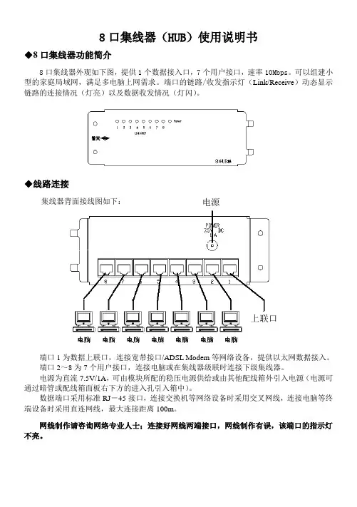
8口集线器外观如下图,提供1个数据接入口,7个用户接口,速率10Mbps 。
可以组建小型的家庭局域网,满足多电脑上网需求。
端口的链路/收发指示灯(Link/Receive )动态显示链路的连接情况(灯亮)以及数据收发情况(灯闪)。
◆线路连接
集线器背面接线图如下:
端口1为数据上联口,连接宽带接口/ADSL Modem 等网络设备,提供以太网数据接入。
端口2~8为7个用户接口,连接电脑或在集线器级联时连接下级集线器。
电源为直流7.5V/1A ,可由模块所配的稳压电源供给或由其他配线箱外引入电源(电源可通过暗管或配线箱面板右下方的进入孔引入箱中)。
数据端口采用标准RJ -45接口,连接交换机等网络设备时采用交叉网线,连接电脑等终端设备时采用直连网线,最大连接距离100m 。
网线制作请咨询网络专业人士;连接好网线两端接口,网线制作有误,该端口的指示灯不亮。
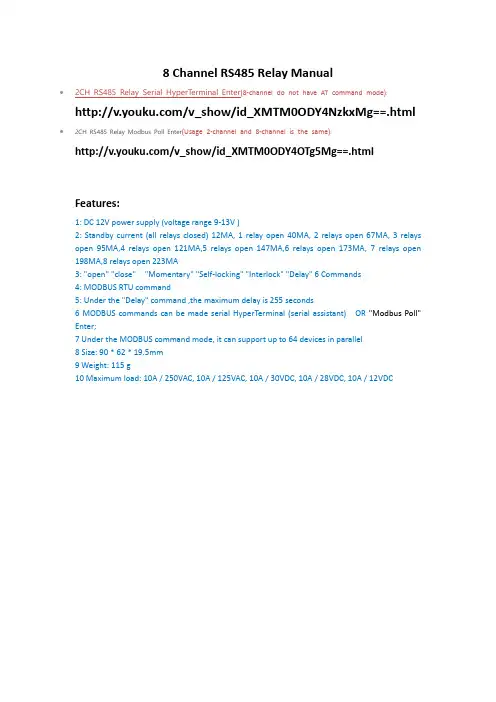
8 Channel RS485 Relay Manual/v_show/id_XMTM0ODY4NzkxMg==.html ∙2CH RS485 Relay Modbus Poll Enter(Usage 2-channel and 8-channel is the same):/v_show/id_XMTM0ODY4OTg5Mg==.htmlFeatures:1: DC 12V power supply (voltage range 9-13V )2: Standby current (all relays closed) 12MA, 1 relay open 40MA, 2 relays open 67MA, 3 relays open 95MA,4 relays open 121MA,5 relays open 147MA,6 relays open 173MA, 7 relays open 198MA,8 relays open 223MA3: "open" "close" "Momentary" "Self-locking" "Interlock" "Delay" 6 Commands4: MODBUS RTU command5: Under the "Delay" command ,the maximum delay is 255 seconds6 MODBUS commands can be made serial HyperTerminal (serial assistant) OR "Modbus Poll"Enter;7 Under the MODBUS command mode, it can support up to 64 devices in parallel8 Size: 90 * 62 * 19.5mm9 Weight: 115 g10 Maximum load: 10A / 250VAC, 10A / 125VAC, 10A / 30VDC, 10A / 28VDC, 10A / 12VDCGlossary:NO : Relay normally open contactCOM : Relay common contactNC : Relay normally closed contactOpen : NO connection COM, NC disconnect COMClose : NO disconnect COM, NC connection COMMomentary : Enter the Momentary command, the Rreceiver Relay is Open, delay of 0.5 seconds after, Relay is Close;Toggle : Enter the Toggle command, the Rreceiver Relay is Open, Enter the Toggle command again, Relay is Close;Latched : Enter the Channel 1 Latched command, the receiver Channel 1 is Open, the Channel 2 is Close.Enter the Channel 2 Latched command the receiver Channel 2 is Open, the Channel 1 is Close. Enter the Channel 3 Latched command the receiver Channel 1 is Close, the Channel 2 is Close.Delay : Enter the Delay command, the Rreceiver Relay is Open, delay of 0-9999 seconds(MODBUS command is 0-255 seconds )after, Relay is Close;During the delay, Eter the Close command, immediately close the relaySlave ID: A0-A5 is the slave ID, you can choose 64 different slave ID.Under the MODBUS command mode,the slave ID must be correctcommand Description, Please refer to "8 Channel RS485 Relay Command"Typical applications:MODBUS command mode (HEX), you can control a variety of ways: Serial Hyper Terminal Control (need to manually add the CRC), Modbus Poll software control (software automatically add the CRC), PLC or MCU process controlWiring Diagram:1 DC 12V control circuit,Wiring diagram below. "LOAD" may be camera,LED lights, fans, motors and other DC 12V equipment2 DC 1-100VAC 85-265V control circuit,Wiring diagram below(Note:If not DC 12V load, need another DC 12V power supply). "LOAD" may be LED lights, fans, motors Lights, fluorescent lights, solar water heaters and other DC AC equipment。

RS485集线器使用说明书(工业级、隔离式一、概述天津三格电子的MS-HUB是一款可通过一路RS-485,一路RS-232为主口扩展出7路RS-485从口的工业级光电隔离型RS-485分配器。
可以有效的实现RS-485网络的中继、扩展与隔离。
采用先进的自动流控技术自动侦测RS-485信号流向。
MS-HUB具备光电隔离功能,电气特性可靠。
每个RS-485口拥有600W TVS防雷保护,使RS-485系统更安全,同时也增加了产品自身的使用寿命。
二、规格与特性电源:宽电源供电,7-36V直流电源,电源带防止反接功能。
接口:上位机接口为一路RS-232,一路RS-485。
下位机接口为7路RS-485。
传输速率:RS-232最高可以达到115200bps;RS-422 、RS-485最高可以达到500Kbps。
速率完全自适应通信方式:RS-232为全双工/ RS-485为半双工。
通信距离:可以达到2000米。
支持点数:每个端口最大32个节点接入。
保护:485 短路保护功能,15KV静电保护,600W浪涌保护,上位机接口和下位机接口具备1KV的隔离,板卡电气特性稳定。
环境温度:-40---60°CMB:130其二二零八零83存储温、湿度:-20---50°C 5%---90%体积:长120mm 宽85mm 高25mm四、LED指示灯POWER:电源指示灯;RS485_1_LED:闪烁表示RS485_1有数据收发;RS485_2_LED:闪烁表示RS485_2有数据收发;RS485_3_LED:闪烁表示RS485_3有数据收发;RS485_4_LED:闪烁表示RS485_4有数据收发;RS48_5_LED:闪烁表示RS485_5有数据收发;RS485_6_LED:闪烁表示RS485_6有数据收发;RS485_7_LED:闪烁表示RS485_7有数据收发;五、装修清单AC220V/DC 9V电源适配器一个,使用说明书一份(销售日期,作为保修的依据),集线器一台。
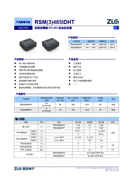
2022.07.12 V1.03 Guangzhou ZHIYUAN Electronics Co.,Ltd.第1页 共5页输入特性参数 符号 条件 最小值 典型值 最大值 单位输入电压V CC RSM3485IDHT 3.15 3.3 3.45 VDC RSM485IDHT4.75 55.25 TXD 逻辑电平高电平 V IH 0.7V CC -- V CC +0.5 低电平 V IL 0 -- 0.3V CC RXD 逻辑电平高电平 V OH I RXD =-1.5mA V CC -0.4 V CC -0.2 -- 低电平V OL I RXD =1.5mA-- 0.2 0.4 TXD 驱动电流 I TXD 2 -- -- mA RXD 输出电流 I RXD -- -- 10 TXD 上拉电阻R TXD--4.7--k Ω 串行接口RSM3485IDHT 3.3V 标准UART 接口 RSM485IDHT5V 标准UART 接口产品特性—————————————————◆ 单一输入电源供电 ◆ 无隔离输出电源脚 ◆ 两路RS-485通道相互隔离 ◆ 自动收发数据功能 ◆ 最多可连接32个节点 ◆ 电磁辐射EME 极低 ◆ 电磁抗干扰EMS 极高◆集成电源隔离、信号隔离和总线ESD 保护功能产品应用————————————————◆ 工业通讯 ◆ 煤矿行业 ◆ 电力监控 ◆ 石油化工 ◆ 楼宇自动化◆ PLC 与变频器的通信 ◆……产品系列————————————————产品型号 温度范围 隔离耐压 封装 RSM3485IDHT -40℃~+85℃ 2500VDC DIP12 RSM485IDHT-40℃~+85℃2500VDCDIP12产品型号———————————————————————————————————————产品型号 电源电压(范围)(VDC) 静态电流 (mA,Typ) 最大工作电流(mA)传输波特率 (kbps) 节点数 (pcs) 类型 RSM3485IDHT 3.3 (3.15-3.45) 20 200 115.2 32 高速 RSM485IDHT 5(4.75-5.25)18150115.232高速参数符号条件最小值典型值最大值单位内置隔离输出电源电压V O标称输入电压4.9 5.1 5.3VDC差分输出电压(A-B)V OD 1.5 -- V O差分输出电流(A-B)I OD 标称输入电压,差分负载为54Ω 28 -- -- mA 总线接口保护ESD静电保护传输特性参数条件最小值典型值最大值单位内置上下拉电阻-- 4.7 --kΩ收发器输入阻抗-7V≤V CM≤+12V 48 -- --数据发送延时-- 1000 --ns 数据接收延时-- 80 --真值表特性收发功能输入输出发送功能TXD A B 1 1 0 0 0 1接收功能V A-V B RXD ≥+200mV 1≤-200mV 0-200mV<V A-V B<+200mV 不确定状态极限特性参数条件最小值典型值最大值单位输入冲击电压(1)(1s,max)RSM3485IDHT -0.7 -- 5VDC RSM485IDHT -0.7 -- 7引脚焊接温度焊点距离外壳1.5mm,10秒-- -- 300 ℃热插拔不支持一般特性参数条件最小值典型值最大值单位隔离电压输入-输出,时间1分钟,漏电流小于1mA 2500 -- -- VDC 绝缘电阻输入-输出,绝缘电压500VDC 1 -- -- GΩ 封装尺寸19.90×16.90×7.10 mm 外壳材料黑色阻燃塑胶外壳,符合UL94 V-0标准环境特性参数条件最小值典型值最大值单位工作温度-40 -- +85℃存储温度-55 -- +125外壳温升Ta=25℃-- 15 25存储湿度无凝结-- -- 95 % 冷却方式自然空冷EMS静电放电抗扰度IEC/EN 61000-4-2 Contact ±4KV/Air ±8KV(裸机) (2) Perf.Criteria B IEC/EN 61000-4-2 Contact ±8KV/ Air ±15KV(图2/图3) Perf.Criteria B 脉冲群抗扰度 IEC/EN 61000-4-4 ±2KV (2)Perf.Criteria B 雷击浪涌抗扰度 IEC/EN 61000-4-5 共模 ±2KV(裸机) (2)Perf.Criteria B IEC/EN 61000-4-5 差模 ±2KV ,共模 ±4KV(图2/图3)Perf.Criteria B 传导骚扰抗扰度IEC/EN 61000-4-6 3Vr.m.s (2)Perf.Criteria A注:(1)输入电压不能超过所规定范围值,否则可能会造成永久性不可恢复的损坏;(2)此参数仅限于RS-485通信端口,Ax 、Bx 或Gx ;测试均为RS-485端口浮地,通信状态下测试; (3)如没有特殊说明,本手册中的参数都是在25℃,湿度40%~75%,输入标称电压下测得。
CANHub-AS8高性能八通道CAN 集线器UM01010101 1.04 Date:2023/3/1©2023 Guangzhou ZHIYUAN Electronics Co., Ltd.修订历史目录1. 功能简介 (1)1.1产品概述 (1)1.2产品特点 (2)1.3产品规格 (2)1.3.1电气参数 (2)1.3.2工作温度 (2)1.3.3防护等级 (3)1.4机械安装尺寸 (3)1.5典型应用 (3)2. 设备硬件接口说明 (4)2.1电源接线 (4)2.2终端电阻拨码开关 (4)2.3CAN通讯接口 (4)2.4信号指示灯 (5)2.5系统连接 (6)3. 驱动程序安装 (7)3.1安装配置软件 (7)4. 快速使用指南 (9)4.1获取设备基本信息 (9)4.2管理设备配置 (11)4.3配置参数说明 (12)4.3.1波特率与终端电阻 (12)4.3.2滤波 (13)4.3.3帧映射 (15)4.3.4路由 (19)4.4查看各通道状态 (20)4.5升级固件 (21)5. 检查和维护 (25)6. 装箱清单 (27)7. 免责声明 (28)1. 功能简介1.1 产品概述本产品实现8通道CAN集线器功能,实现8个通道CAN帧接收、缓存、帧映射、帧转发等功能。
通过UART(USB或RS232)使用类似ModBus协议与上位机通信,实现CANHub-AS8的功能配置。
CANhub-AS8能实现多个CAN网络的透明连接,可以在总线级别实现复杂结构的多点连接;CANhub-AS8使得主干网络没有支线长度限制,网络中任意两个节点可以到达协议距离,该设备具有8个通信端口,每个端口都有独立的CAN收发器,能倍增节点数目,因此,在提供自由的布线方式的同时,也解除了系统总线上CAN收发器最大节点数驱动限制。
每个端口还具备检测总线活跃及总线故障指示灯,方便观察CAN总线网络工作状态。
Introduction of USB-8COMi-MThe USB to industrial Octal RS-422/485 Adapter is designed to make serial port expansion quick and simple. Connecting to a USB port on your computer or USB hub, the USB Serial Adapter instantly adds 8 RS-422/485 multi-electrical interface serial communication ports to your system. By taking advantage of the USB bus, the USB-8COMi-M Adapter makes it easier than ever to add 8 RS-422/485 ports and serial devices to your system with easy plug-and-play and hot plug features. Adapting the new technology, the serial port expansion now takes the new bus with easy and convenient connectivity.Plugging the USB 8-Port RS-422/485 Adapter to the USB port, the adapter is automatically detected and installed. There are no IRQ & COM port conflicts, since the port doesn't require any additional IRQ, DMA, memory as resources on the system. The RS-422/485 port functions as native Windows COM port, and it is compatible with Windows serial communication applications. Each port is individually configurable. The adapter is designed with external switches to set the RS-422 or RS-485 ports and different operation modes conveniently. There is no need to open the chassis to set the ports.The USB Serial Adapter provides instant connectivity to RS-422 or RS-485 communication devices for factory automation equipment, multi-drop data collection devices, barcode readers, time clocks, scales, data entry terminals, ATMs and serial communication in harsh environment. The USB to Serial Adapter is suitable for remote access, retail and industrial application, data collection and other applications requiring high speed RS-422/485, communication ports. Specifications & Features●Adds eight high speed RS-422 / 485 serial ports via USB connection.●384 byte receive buffer.●128 byte transmit buffer for high speed data throughput.●Requires no IRQ, DMA, I/O port.●Data rates: 300 bps to 921.6K bps.●Serial Connector: one DB-9 male connector.●Auto transmit buffer control for 2-wire RS-485 half-duplex operation.●Termination resistors installed on-board.●RS-422 data signals: Tx-, Tx+, Rx+, Rx-, GND, RTS-, RTS+, CTS+, CTS-.●RS-485 data signals: Tx-, Tx+, Rx+, Rx-(4 wire) and data-, data+ (2 wire).●Monitor LEDs of TxD, RxD indicating port status.●Power Supply: provides an external DC12V power adapter●Virtual COM port drivers available for Windows 7, Vista, 2003, XP, 2000.Hardware InstallationOutside the unit, there are eight 3-pin DIP switches which are set to select the mode of operation. You will need to set the switch settings to RS-422 or RS-485 mode as per the requirements of your application.You need to install driver first, prior to hardware installation. After the setting of DIP switches and connecting power cord to the adapter, you then plug the adapter to USB port to start driver installation.The Mode Block Configuration Settings are listed as follows:SW1 (Port-1), SW2 (Port-2), SW3 (Port-3), SW4 (Port-4)SW5 (Port-5), SW6 (Port-6), SW7 (Port-7), SW8 (Port-8)JP3 (Port-1), JP4 (Port-2), JP5 (Port-3), JP6 (Port-4)JP7 (Port-5), JP8 (Port-6), JP9 (Port-7), JP10 (Port-8)for Termination and Biasing Option ConfigurationInside the unit, there are eight 2 x 7 (14 pin) header blocks which are jumpered to enable Tx, Rx, CTS 120 Ohm termination resistors and Tx, Rx 750 Ohm BIASing resistor.You will need to open up the metal case and set the jumper setting for RS-422 mode or RS-485 mode as per the requirements of your application.Settings are listed as follows:Note: Sometimes, when operating in RS-422 or RS-485, it is necessary to configure termination and biasing of the data transmission lines. Generally this must be done in the cabling, since this depends on the installation of connections. Before applying the option, check your cable specification for proper impedance matching.You need to have administrator privileges to install any new drivers under Windows 7/ Vista / 2003 / XP / 2000. To install the driver or update the configuration please log onto Windows as "Administrator" or ask your system administrator to install the USB-COM driver.You need to install driver first, prior to hardware installation. Do not connect the USB-to-Serial Adapter to the USB port of your computer, before you finish driver installation.Please proceed with the following steps to install the driver:1. Insert the “USB COM Series Driver and Utility” CD into your CD-ROM.2. The “USB COM Series Driver and Utility CD” dialog box appears.3. Under “Driver Installation”, double click “Windows 7, Vista, 2003, XP, 2000driver” to install the device driver.4. The USB COM install program will auto-detect the OS type and install thedriver automatically. (Note: in Windows 7 or Vista OS you will find anotherdialog box, please click on “OK” to confirm the drivers install program).5. After the message “FTDI CDM Driver installation process completed”appears, press “Enter” to complete the driver installation.6. Plug in the USB to Serial Adapter to the USB port of your computer.Windows will finish installing the driver files.Check InstallationYou can now verify the installation has been completed successfully by looking under Device Manager of the System Properties screen. (Go there by Start-Setting- Control Panel-System Properties-Hardware-Device Manager.The device should have installed as a "USB Serial Port (COMx)" attached to "USB Serial Converter A/B/C/D".Change COM Port Properties & COM Port NumberThis feature is particularly useful for programs, such as HyperTerminal, which only work with COM1 through COM4. Please ensure that you do not change the COM Port Number already in use.To change the virtual COM port properties:●Select the "USB Serial Port"●Click “Properties”.●Select "Port Setting" and “Advanced”.●Click the drop down arrow on COM Port Number and scroll to the required COMport. Select "OK".●Return to the Device Manager Screen. You will see that the USB Serial Portinstallation has been changed to the new COM Port Number.Uninstalling Windows 2003/XP/2000 DriversPlease proceed with the following steps to uninstall the 2003/XP/2000 driver:1. Insert the “USB COM Series Driver and Utility” CD into your CD-ROM.2. The “USB COM Series Driver and Utility CD” dialog box appears.3. Under “Driver Uninstalling”, double click “Windows 2003, XP, 2000 driveruninstall” to uninstall the device driver.4. When following dialog box appears, double click “Clean System” touninstall the 2003/XP/2000 drivers.5. You need to disconnect all USB to serial Adapters from your PC, when themessage below appears. Double click “OK” to start uninstalling Windows2003/XP/2000 USB to Serial drivers.6. Double click “Yes” to confirm it.7. Click “No” to proceed.8. When the message “Status: System clean completed” appears, double click“Exit” to complete the USB to serial drivers uninstall.9. Press “Start” button and select “Control Panel”.10. Open the Add or Remove program.11. Remove the first “Windows Driver Package – FTDI CDM Driver Package (…)”.12. Click “Chang/Remove” and “Yes” to remove the first Windows DriverPackage.13. Remove the second “Windows Driver Package – FTDI CDM Driver Package(…)”.14. Click “Chang/Remove” and “Yes” to remove the second Windows DriverPackage.15. Reboot the computer to complete the driver uninstall.Uninstalling Windows 7 or Vista DriversWindows 7 and Vista have many new security features. You need to proceed with the following steps to uninstall the Vista driver:1. The USB to serial devices must connect to the PC.2. Press “Start” button and select “Control Panel”.3. Select “Classic View” from the top left hand corner and then “System” fromthe list.4. Select “Device Manager” from the top left hand corner.5. Locate your Device under the Ports (COM & LTP) section and right click onit to bring up the menu shown.Note: if you have more than one USB Serial Port (COMx) installed in your PC, you need to repeat from step 5 to step 6 to delete the driver software for each port.7. Locate your Device under the Universal Serial Bus Controllers section, andright click on it to bring up the menu shown.Note: if you have more than one USB Serial Converter installed in your PC, you need to repeat step 7 and step 8 to delete the driver software for all devices.RS-422 Signal Pin-outs of DB-9 MaleRS-422 Signal Wiring● Point- to- Point 4 Wire Full Duplex● RS-422 with Handshaking2 TxD+(B) RxD+ (B) RxD- (A) TxD+(B) TxD- (A) GND USB-8COMi-M RS-422 Device1 TxD- (A) 3 RxD+ (B) RxD- (A) 5 GND 7 RTS+(B) CTS+(B) 6 RTS- (A) CTS- (A) 8 CTS+(B) RTS+(B) 9 CTS- (A)RTS- (A)4 2 TxD+(B) RxD+ (B) RxD- (A) TxD+(B) TxD- (A)GNDUSB-8COMi-M RS-422 Device 1 TxD- (A) 3 RxD+ (B) RxD- (A)5 GND 4RS-485 4-Wire (Full duplex) Signal Pin-outs of DB-9 MaleRS-485 2-Wire (Half duplex) Signal Pin-outs of DB-9 MaleRS-485 Signal WiringPoint-to-Point 4-Wire Full Duplex2 TxD+(B) RxD+ (B)RxD- (A) TxD+(B) TxD- (A) GNDUSB-8COMi-M RS-485 Device1 TxD- (A) 3 RxD+ (B) RxD- (A) 5 GND4Multidrop RS-485 2-Wire Half-duplexAll brand names and trademarks are the property of their respective owners.Manual Part No. USBG051Data+(B) Data- (A) GND| | | | |Data+(B) Data- (A) GNDUSB- 8COMi-M2 Data+(B 1 5 GND。

485集线器HUB产品功能及应用介绍!485是一款4口光隔RS-485/422总线分割集中器,实现232/485转换器、RS-232/422双向转换及RS-485/422中继功能,一路进4路出。
集线器是一款专为解决复杂通信环境下485大型系统总线形式要求而设计的485HUB总线集线器。
可以提供更加灵活的RS-485星型总线结构RS-485接口输入、输出端均采用独立驱动方式,改变原有总线的单一式结构为星型网络结构,可以使485总线通信系统的稳定更好。
一、485HUB基本介绍485集线器RS-485/422接口在工业控制中使用相当普遍,采用的都是总线挂接式连接方式,不支持星型连接,一根总线支持的设备有限,且传输距离只有1200米,从而给施工带来了极大的不便,期待着RS-485/422总线分割集中器的诞生。
二、485HUB总线分割H-4485能够轻易的改善系统的总线结构,无需改动设备本身,就能实现不同功能的设备或不同区域的设备分别对待,并构成相互独立的不同网段。
不仅提高了系统的可靠性,而且大大的缩短了系统的维护时间。
星形连接:H-4485通过特殊设计能够向用户提供RS-485/422星型连接方式,从而改变了原有总线单一式结构,为网络结构工程建设带来了极大的便利。
三、485HUB光电隔离在工业控制领域,RS-485总线往往需要把分散的不同设备相互连接起来协同工作,由于环境差异的存在,设备与设备之间往往存在着不同程度的地电位差异,从而影响设备的正常通信。
H-4485为所有端口都提供2500V以上的光电隔离,有效地解决了由距离及地电位差异带来的传输问题。
短路开路保护H-4485在所有端口处都设有短路开路保护,能够保证当其中一个端口设备故障产生时,出现问题的端口将被隔离,以确保其他网段能够正常工作。
1本光纤集线器用于组建星型光纤网络,实现RS-232/485/422在光纤星型网络上透明传输。
完全自适应,无需改动用户协议。
由于采用了光纤作为传输介质,可以完全避免恶劣环境下雷电、浪涌、电磁干扰等对通信设备的威胁,同时省去了原来使用铜线时的雷电浪涌保护设备投资,大大提高了数据通讯的可靠性、安全性和保密性。
具备自动侦测串口信号波特率的能力可以自动检测、控制RS-485数据流,不必要用握手信号来控制数据流向支持RS232/422/485接口,RS232波特率支持300-256K,RS485/422波特率300-921K可与8个远端RS232/422/485串口Modem 组成星型网络 自动检测每个光口的串口数据是否正常,自动屏蔽不正常的光接口(如所在的光纤modem 串口打坏收到全0,或线路短路),使其不影响整个网络,并有指示灯指示有4U 机框卡片式,支持8块光纤集线器,总共有64个光方向,可以SNMP 网管串行口接口防雷达到IEC61000-4-5(8/20μS)差模:6KV,阻抗(2Ω);共模:6KV,阻抗(2Ω)标准◆光纤部分多模光纤:50/125um 或62.5/125um,传输距离:2Km 多模光纤,衰减(3dbm/km )波长:1510nm 发射功率:-12dBm (Min)~-9dBm (Max)接收灵敏度:-28dBm (Min)链路预算:16dBm单模光纤:8/125um或9/125um,传输距离:20Km单模光纤,衰减(0.35dbm/km)(实际如需更大距离需定制)波长:1310nm(超长距离传输时选用1550nm波长)发射功率:-9dBm(Min)~-5dBm(Max)接收灵敏度:-27dBm(Min)链路预算:18dBm◆数据接口数据接口:RS-485/RS-232/RS-422/Manchester/TTL数据格式:NRZ、Manchester、Bi-phase速率:110bps-115.200Kbps物理接口:RJ45◆电气和机械特性系统电源:AC180V~260V功耗:≤5W外观结构:(长×宽×高)186*138*43桌面式◆环境指标工作温度:-10℃—+70℃或-40℃—+85℃(工业级)储存温度:-40℃—+85℃工作湿度:0%—95%(无凝结)MTBF:>100,000小时产品名称8路串口光纤集线器产品功能描述实现8路RS485/RS232/RS422数据信号在光纤星型网络上传输,可与数据光猫连接,桌面式,-48V或AC220V电源(可选)业务端口描述8路光纤通道电源AC220V或DC-48V(电源可选)产品尺寸(长×宽×高)186*138*43桌面式重量 1.2Kg/台23飞畅科技专注光纤通信研发、生产、销售20年,为客户提供个性化技术服务与定制解决方案。
KSV8八网口二合一视频控制器版本: v1.0发布日期: 2023年02月使用说明书版本记录版本号变更详情发布时间V1.0 第一次发布2023.02.01安全注意事项危险●设备内有高压,非专业维修人员不得打开后盖,以免发生危险。
警告●本设备非防水设备,在潮湿环境下请做好防水处理;●本设备禁止靠近火源或高温环境;●本设备如发出怪异噪音、冒烟或怪味,应立即拔掉电源插头,并与经销商联系;●严禁带电拔插DP、DVI、HDMI信号线缆。
注意1、使用前请仔细阅读本说明书,并妥善保存以备后用;2、在有雷电或长期不用的情况下,请拔掉电源插头;3、本设备不适合非专业人员操作调试,请在专业人员指导下使用;4、不要从本设备通风孔塞入任何物体,以免造成设备损坏或事故;5、不宜将本设备放置于近水或其它潮湿的地方使用;6、不宜将本设备放置于散热片或其它高温地方使用;7、请妥善整理并放置好电源线,以防破损;8、如存在下列情况,应拔掉本设备电源插头,并委托维修:●有液体溅入本设备时●本设备跌落或机箱损坏时●本设备出现明显功能异常或性能明显变差时声明感谢您使用本公司的产品。
本文档版权属本公司所有,在未征得本公司的书面许可的情况下,严禁以任何形式复制、传递、分发和存储本文档的任何内容。
本公司保留在不预先通知的情况下对本文档中所描述的任何产品功能进行修改和改进的权利,最终解释权归本公司所有。
本产品可能附带有相关的控制软件,该软件仅供您使用,软件的所有权归本公司所有。
您可以进行拷贝,但仅限于个人使用。
若您将此软件用于其它用途,特别是商业用途,请与本公司取得联系。
本公司保留追究侵权行为法律责任的权利。
请您在使用前仔细阅读本手册,操作不当,有可能对产品造成损害;本产品为带电工作产品,请注意用电安全。
若不按照本手册的说明,采取不得当的操作,因而造成的财产损失和人身伤害,本公司不承担责任。
此条如与当地法律法规相抵触之处,以当地法律法规为准。
如果您使用了本产品,意味着您同意以上声明,若您不同意以上声明,则请您与销售方联系,办理相应的退货手续。
F e a t u r e s• 2 Port RS422/485•Universal PCI•128 Byte FIFO with user definable trigger level •Up to 921,600 baud •Standard Profile•Full Duplex and Half Duplex Autogating •Optical Isolation:±1500 Volt DC, 1000 Volt AC •Transient Spike Protection •Drivers for all popularoperating systems•Sample Programs, Test &Terminal software - all with source code •Lifetime Support and Lifetime Warranty Click on each feature to find similar productsOpto IsolationUNIVERSAL DUAL OPTO VELOCITY RS422/485D e s c r i p t i o nUniversal PCI card providing 2 industry standard 9 pin RS422/485 serial COM ports in a single PCI slot. Velocity megabaud data transfer rates and 128 byte deep FIFO guarantees uncompromising performance and fault-free use.Optical isolation provides greater protection from electrical current surges to both the card itself and the PC.Universal PCI is fully compatible with both 3.3Volt and 5Volt PCI slots; protecting your investment into the future. Now with Brainboxes Lifetime Warranty and Lifetime Support!S o f t w a r eMicrosoft signed drivers (easy installation & robust operation) for:o Windows Server 2003 x32 bit & x64 bit Editions o Windows XP x32 bit & x64 bit Editions oWindows 2000.Fully tested drivers also included for:oWindows Me, Windows 98 & 95, Windows NT .As well as: full product documentation, a thorough troubleshooting guide and terminal software. Detailed sample source code for all popular programming languages.Need support for other operating systems? Please telephone or email.Find out about Brainboxes excellent driver configurability: Click HereORDER DescriptionCode UNIVERSAL DUAL OPTO VELOCITY RS422/485UC-310‘UC-310SERIAL CARDS ENGINEERED TO EXCEED EXPECTATIONS ‘A p p l i c a t i o n s•Cash Deposit Machine •Long Distance Communication •Industrial Sector•Banking & Financial SectorProduct of the Year WINNERManufa c t u re r of t h e Yea rWINNERUNIVERSAL DUAL OPTO VELOCITY RS422/485Product CodeUC -3310Serial PortPorts2 Port RS422/485Connector DB9 (9 Pin Male)UART type 16950 UART inside Brainboxes LYNX BB16PCI958FIFO size128 Byte with user definable trigger level Transmitted Signal Strength +/- 5 Volts open circuit RS422/485 Standard Operating Distance 4000 ft (1200 metres) RS422/485 StandardElectrical Protection*Opto-Isolation: +/- 1500 Volt DC / 1000Volt AC+ve transient spikes > 12V , -ve transient spikes >6.8V Serial Port SettingsBaud Rate (bits per second)up to 921,600Data Bits 5,6,7 or 8Parity Odd, Even, None, Mark or Space Stop Bits 1, 1.5 or 2Flow Control CTS/RTSIRQsPlug and Play - Shared interrupts for all ports Tx/Rx ModesFull Duplex, Half Duplex Autogating Connection Schemes Point to Point,One talker; many listeners, (32 Max)Many talkers / listeners Half Duplex (32 Max)RS485 GatingHardware Autogating, TxD always / RTS true enabled,RxD always enabled, RxD RTS true disabled, CTS forced true GeneralBracket Profile Standard PCB Layers 4Power 550mA @ 5V Weight 0.097KgSize93 x 122 mmInterfaceBUS Compatibility 32/64 bit Universal (3.3V or 5V) PCI or PCI-X OS Compatibility Windows 98/ NT4/ 2000/ XP/ Server 2003Windows XP x64 bit Edition / Windows Server 2003 x64 bit LinuxPCI ComplianceVersion 3.0Approvals & Accreditations UL, EMC: CE, FCC, PCI Power Management 1.1 Compliant, PCI 3.0 CompliantBox ContentsInstallation CD including manual, Microsoft signed drivers, utilities and sample programs with source code UNIVERSAL DUAL OPTO VELOCITY RS422/485Installation GuideOEM option Available for bulk buy OEMProduct Support Lifetime Email and Phone Supportfrom Fully qualified, friendly staff 40 hours a week Warranty LifetimeMade InManufactured in the UK by BrainboxesWinner 2005 European Electronics Industry Awards “Manufacturer of the Year”CustomisableBrainboxes operate a "Perfect Fit Custom Design" Product of the Year WINNERManufa c t u re r of t h e Yea rWINNER Pin 1 TXD- Pin 2 TXD+ Pin 3 RTS- Pin 4 RTS+ Pin 5 GND Pin 6 RXD- Pin 7 RXD+ Pin 8 CTS- Pin 9CTS+123 4 56789RS422/485Pinout (9 pin Male)UNIVERSAL DUAL OPTO VELOCITY RS422/485Glossary:Product Features ExplainedUniversal PCIUniversal products allow compatibility with both 3.3 Volt and 5 Volt PCI systems. This ensures that Brainboxes universal card range is backward compatible with older systems and works with all new PCI systems.More info on'Universal'products:Click HereAutogatingWhen the device is set to half duplex mode, transmitted and received data is sent across the same signal lines.Autogating means the Brainboxes card knows when to 'listen' for data and when to transmit data, with a quick and automatic hardware switch between the 2 modes. This is much faster than software switching and ensures no data loss due to turnaround delay.More Info:Click HereOpto IsolationOptical isolation provides greater protection from electrical current surges to both the card itself and the PC. It improves noise immunity by isolating the PC from the card’s transmit ground.Opto-Isolation: ±1500Volt DC/ 1000Volts ACPCI CompliantAll Brainboxes Universal PCI cards are fully PCI version 3.0 compliant, in accordance with the PCI-Special Interest Group (PCI-SIG).Large FIFOFIFO means First In First Out, a FIFO is memory space on the Brainboxes card. A larger FIFO allows more memory space for buffering data, so calls to the computer processor are less frequent. This significantly increases data throughput and improves CPU availability for other applications.More info:Click Here4Layer PCBPrinted Circuit Board with 4 layers of circuitry complies with the PCI SIG best practice guideline and ensures a more reliable card. 1 layer is for power and 1 for ground which leads to greater EMC shielding for the signals. This ultimately gives greater signal integrity for sensitive timing applications.Surface Mount ComponentsMost components on a Brainboxes card are placed by a surface mount machine. The surface mount machine allows for highly accurate and fast production of Brainboxes cards. Orders can be met quickly, reliably and with outstanding quality.CapacitorsAs required by the PCI-SIG all Brainboxes cards have capacitors connected to all the power pins on the PCI connector, near to the connector. This ensures that the electrical power rails on the Brainboxes card stay at the right voltage, regardless of the power demands placed on them. Data signals keep their integrity.UNIVERSAL DUAL OPTO VELOCITY RS422/485B r a i n b o x e s ' K a i z e n"Brainboxes constantly strives to achieve higher standards for the benefit of customers."‘Kaizen’ is a Japanese term meaning ‘continuous improvement’. Kaizen has been implemented throughout Brainboxes, resulting in significant improvements to our products and our customer service,as illustrated by the development of our own custom ASIC “LYNX” and our new lifetime warranty. As part of this ongoing process, in 2004 we embarked on ‘Lean’ and ‘6 Sigma’ programs which are successfully increasing productivity and efficiency in all areas of the company.More Info:Click HereB r a i n b o x e s ' S e r v i c e“Brainboxes offers free lifetime support for ALL customers.”We aim to provide industry leading support for our customers. Our highly trained and helpful supportengineers sit and work closely with the product designers, developers, and testers to ensure an in-depth knowledge of the products. Support can be found by emailing **********************or calling: +44 (0)151 220 2500 during UK office hours. Support website: /support/index.asp“Brainboxes’ passionately believes in the quality of its manufacturing process and will reflect this byoffering a Lifetime Warranty on ALL of its universal serial card range.”Brainboxes is pleased to be able to extend a new Lifetime Warranty for all universal serial cards products.We have introduced this based on our exceptional manufacturing and design quality and the company ethos of kaizen.R S 422/485 S t a n d a r d sRS422 allows one transmitter and up to 10 receivers with data transmission rates up to 10 Megabits per second, for distances up to 40 feet and up to 100 Kilobits per second, for distances up to 4000 feet (1219 metres).RS485, based on the RS422 standard, allows up to 32 driver/receivers pairs on a party line data bus. This can be configured into half duplex and full duplex mode. Whilst only one of these should be transmitting data at any time, the rest can all simultaneously listen to the data.More Info:Click HereB r a i n b o x e s ' L Y N XWe developed the Brainboxes LYNX (BB16PCI958) to enable us to drive product performance, and supply customer needs for Universal PCI products (3.3v and 5v compatible). By reducing the part count and incorporating several components into one chip (FIFO, UARTs, PCI interface), we have also increased board reliability. The LYNX also features thorough backwards compatibility with legacy systems, tested beyond the databook for compatibility with standard TL16C550, 750 UARTs. The chip is designed so that Brainboxes products will work with all applications designed for TI UARTs. More Info:Click HereRS422/485 Pinout。
ZLAN9480A RS485 HUB用户手册1 路RS485转8路RS485集线器版权©2008 上海卓岚信息科技有限公司保留所有权力ZL DUI 20150422.1.0版权©2008 上海卓岚信息科技有限公司保留所有权力版本信息对该文档有如下的修改:修改记录日期版本号文档编号修改内容2015-04-22 Rev.1 ZL DUI 20150422.1.0 发布版本2018-05-13 Rev.2 ZL DUI 20150422.1.0 修改版本所有权信息未经版权所有者同意,不得将本文档的全部或者部分以纸面或者电子文档的形式重新发布。
本文档只用于辅助读者使用产品,上海卓岚公司不对使用该文档中的信息而引起的损失或者错误负责。
本文档描述的产品和文本正在不断地开发和完善中。
上海卓岚信息科技有限公司有权利在未通知用户的情况下修改本文档。
目录1.概述 (4)2.特点 (5)3.技术参数 (6)4.硬件说明 (7)5.使用方法 (8)6.售后服务和技术支持 (8)上海卓岚信息科技有限公司Tel:(021)64325189 1. 概述ZLAN9480A是一款可通过一路RS485主口扩展出8路RS485从口的工业级隔离型8口RS485集线器。
可以有效的实现RS485网络的中继、扩展与隔离。
图1 ZLAN9480A外观ZLAN9480A的主口端提供隔离型RS485,从口端扩展出8路隔离型RS485接口。
一般RS485接线时要求手拉手接线方式,需要避免主站为中心的星型连接。
但是某些情况下为了方便,需要采用星型连接,此时采用RS485 HUB可以有效隔离多个RS485之间的连线干扰。
ZLAN9480A有源隔离型RS485集线器产品是专门针对工业现场恶劣环境而设计的,对于那些要求高可靠性和安全性的场合尤其适合。
光电隔离功能可以有效的使RS485主从设备之间彼此隔离开来,避免因主从设备间的地电位差、以上海卓岚信息科技有限公司Tel:(021)64325189 及静电、雷击和浪涌对RS485主从设备造成的损害,同时也有效的避免了主从设备端的地电位差而在设备间产生的地环流对RS485设备造成的损害。