HPc7000刀片服务器安装手册
- 格式:ppt
- 大小:6.26 MB
- 文档页数:24
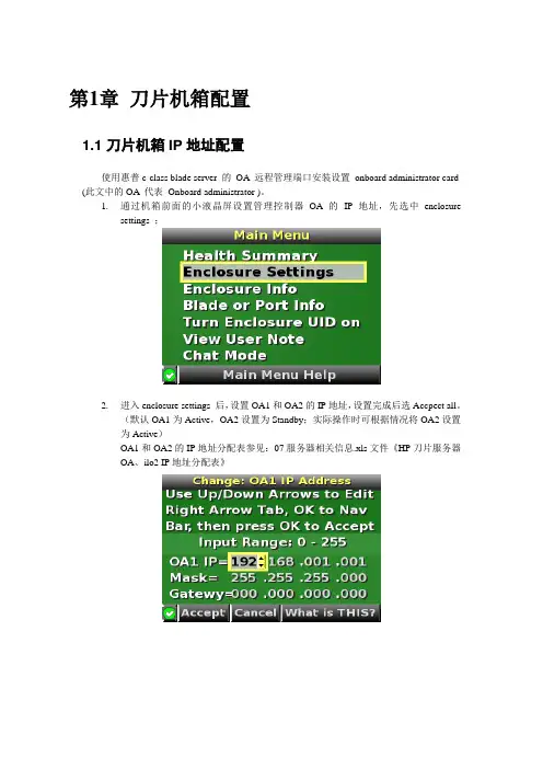
第1章刀片机箱配置1.1 刀片机箱IP地址配置使用惠普c-class blade server 的OA 远程管理端口安装设置onboard administrator card (此文中的OA 代表Onboard administrator )。
1.通过机箱前面的小液晶屏设置管理控制器OA的IP地址,先选中enclosuresettings ;2.进入enclosure settings 后,设置OA1和OA2的IP地址,设置完成后选Accpect all。
(默认OA1为Active,OA2设置为Standby;实际操作时可根据情况将OA2设置为Active)OA1和OA2的IP地址分配表参见:07服务器相关信息.xls文件《HP刀片服务器OA、ilo2 IP地址分配表》1.2 登录机箱IP,进行刀片设置1.2.1 Administrator用户配置1.通过终端的IE6.0 浏览器输入刀片服务器的OA 口的ip 地址:192.168.1.1,进入OA的登录界面,输入机器前方的纸片的出厂OA的用户名和密码登录;2.登录后进入Rack Overview 界面,它把刀片的硬件状态很直观的以图片方式展现,包括设备正反面板图片示意等信息;3.如果是第一次安装刀片服务器机箱,直接进入first time setup wizard ;4.进入Configuration Management,用它可以快速重载一个以前配制好的OA设置;5.Rack and Enclosure Settings,设置机箱的名称、时间、时区等;6.Administrator Account Setup 设置管理员帐户(Administrator 口令:123);Administrator 是管理员权限,可管理所有的刀片服务器,PIN protection 可以启用(目前未启用)、设置PIN Code 来给刀片服务器前面的液晶屏设置密码;1.2.2 Local Users用户配置用户的建立1、以管理员身份登陆到OA系统,在机框列表中选中要控制的机框。
刀片OA下安装操作系统HP服务器下,安装操作系统的方式有两种,一种是直接用光驱挂载镜像安装,另外一种是通过ILO远程挂载镜像安装,在刀片服务器安装系统我们建议使用远程ILO挂载镜像安装。
在HP服务器中,安装Linux或者windows系统的方式都是一样的。
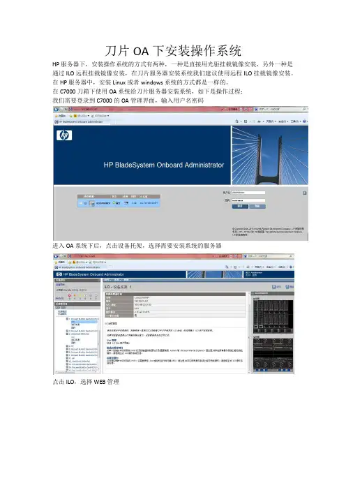
在C7000刀箱下使用OA系统给刀片服务器安装系统,如下是操作过程:我们需要登录到C7000的OA管理界面,输入用户名密码进入OA系统下后,点击设备托架,选择需要安装系统的服务器点击ILO,选择WEB管理进入ILO管理界面,(此界面可以看到服务器的信息)选择Remote Console----Launch备注:在打开ILO远程窗口时,对浏览器的插件有要求,如果是IE浏览器的话需要安装.NET4.0以上,如果使用Google浏览器的话,需要安装Java。
在弹出的窗口点击Run进入ILO远程窗口,挂载镜像确定之后,即可进行安装操作系统,HP服务器安装操作系统有两种方式,第一种是直接安装,此方式的有点是安装速度快,但是系统下的一些驱动需要手动安装。
另外一种是F10引导安装,此方式下,安装过程比较慢,但是系统下的驱动是已经安装完成的,按需要选择适合的安装方式。
进入服务器的自检过程,进行阵列设置,在自检到阵列卡的时候按F8键(备注,此操作在HP服务器下仅适合GEN8服务及以前旧一代服务,最新GEN9服务需要在其他界面进行操作,下图有介绍。
)进入后,选择Create Logical Drive 按Tab键可进行选择,选择需要设置的Raid级别。
按ESC键退出后即可以安装系统,直接安装系统跟传统安装系统过程是一样的如下是F10引导安装,以及GEN9阵列创建(此操作也适应在GEN8服务器)在开机自检过程中,按F10进入,在进入操作界面之前不需要任何操作进入操作界面,选择Perform Maintenance选择HP Smart Storage Administrator (SSA)进入后,选择阵列卡-configure-按过程操作如上是阵列操作,如下是安装系统操作还是之前按F10进入的操作界面。
某单位C7000刀片服务器安装报告
一、设备清单
二、系统安装介绍
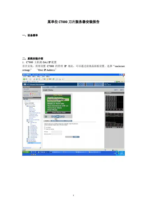
1.C7000 主机箱OA1 IP配置
首次安装,需要设置C7000的管理IP地址,可以通过前液晶面板设置。
选择“enclosure settings”-----“OA1 IP Address”
首先通过IE 地址栏进入OA1配置页面。
选项入下图:
3.WINDOWS 2003系统的安装
在IE地址栏输入被安装刀片的ILO2 地址或点击OA1配置页选择被安装服务器,通过MOUNT 加载HP SMARTSTART ISO,机器会通过该光盘自动引导安装。
WINDOWS2000
安装方法一样。
再点ILO,选2项
普通机器安装过程一样!
目前的OA IP地址为:10.137.110.230 管理员用户名为:admin 密码:admin 各刀片服务器的ILO IP 地址从左至右依次为:
192.168.0.101
192.168.0.102
192.168.0.103
192.168.0.104
192.168.0.105
192.168.0.106
每台刀片机的WIN2003系统管理员密码为:123456
每台只有一个20G的C盘主分区,其它分区客户按自身需求分配剩佘硬盘空间!
三、HP 硬件故障保修
硬件故障报修电话:800-810-3888
维修中心电话:
安装工程师手机:。

HPBlade SystemC7000安装运行基本操作指南C7000是HP公司新型号的刀片中心,其可装载16台刀片服务器,并有十个网络模块插口。
由于刀片中心上并没有任何的光驱软驱设备,也没有任何的视频输出口。
如想将刀片中心上的刀片服务器投入使用只有通过W AN口用交叉线将刀片中心外接自用PC机方可进行相应的配置,保证其投入使用。
对C7000的安装运行操作基本如下:一.通过一根交叉线将刀片中心与调控端的电脑(推荐使用笔记本电脑)相连。
将网线接入刀片中心的一段接到刀片中心的OA口,其后在刀片中心前端显示屏上对刀片中心进行IP上的分配,通过显示屏的上下与OK键在“Enclosure settings”一项里选中IP地址进行设置,其中子网掩码一定要配好(在此以IP:192.168.2.127 掩码:255.255.255.0为例)。
之后将控制端的地址于刀片中心的地址配为同一段。
(以IP:192.168.2.126为例)(如图)二.在控制端的IE浏览器里输入刚配给刀片中心的地址,要以一种加密的连接形式进行接入,即:https://192.168.2.127,如图二点继续进入,在此推荐使用浏览器为IE7三.进入到登陆界面,输入用户名,密码。
用户名密码位于悬挂在刀片中心的纸片上。
个刀片,安装几个网卡模块,并可在左侧的故障提示栏内看到相应的刀片中心存在的错误。
五.接下来是对每一台刀片服务器进行配置,目的是让管理员可对每台刀片服务器进行控制。
在管理首页面的左侧菜单中点中Enclosure Settings前的加号,在下拉菜单中选中Enclosure Bay IP Addressing项,会在页面的右侧出现如下图所示画面,会出现1----16相对应的陈列项,即1----16相对应的刀片插槽,在插入刀片服务器的插槽里会在右侧出现相应的地址,并且状态显示为Server Blade,将需要操作的刀片服务器改成与刀片中心和控制端电脑相统一的网段并执行保存。

HP BladeSystem c7000 Enclosure Quick Setup InstructionsPart Number 411762-007February 2010 (Seventh Edition)Verifying the pallet contents* Not shownInstalling the enclosureWARNING: Because the fully-populated enclosure canweigh up to 217.7 kg (480 lb), remove all componentsand the rear cage from the enclosure before removingthe enclosure from the pallet to reduce the risk ofpersonal injury when moving the enclosure.CAUTION: When removing the rear cage andmidplane assembly, the connectors on the midplaneassembly are susceptible to damage. Use caution toavoid damage to the pins and connectors.CAUTION: Be sure the hinges are completely openbefore installing the rear cage into the enclosure.Failure to do so can cause damage to pins andconnectors.1.The enclosure can be installed in a rack or rack-freeenvironment. Select the proper location based on requirementsdetailed in the HP BladeSystem c7000 Enclosure Setup andInstallation Guide.2.Remove all components from the front and rear of theenclosure, and then remove the rear cage.3.(Optional) Install the enclosure into a rack. See the HPBladeSystem c7000 Enclosure Rack Template. For rack-free installations, omit this step.4.Install the rear cage into the enclosure, close the hinges, andtighten the thumbscrews.Enclosure bay identificationBefore installing front or rear components into the enclosure, review enclosure bay numbering for each component.Full-height device bay numberingHalf-height device bay numberingPower supply bay numberingFan bay numberingInstalling the front componentsCAUTION: To prevent improper cooling and thermal damage, do not operate the enclosure unless all bays are populated with a component or a blank.CAUTION: Do not mix HP 2250W, HP 2400W High Efficiency, HP BL7000 2400W Platinum, or -48vDC power supplies in one enclosure. Install only one type of power supply in a single enclosure.If your HP BladeSystem c7000 Enclosure is equipped with a three-phase power configuration, you need six power supplies. To install a power supply: 1. To gain access to all power supply bays, slide the HP BladeSystem Insight Display to the right or left as needed. 2. Remove the power supply blank.3.Insert the power supply into the enclosure, and then close thepower supply bracket.NOTE: This document discusses installation of ACpower supplies only. For information on configuring DC power supplies or HP Carrier Grade Solutions, see the documentation that came with your power supply.4. Add any ordered options to each server blade: o Additional processor o Additional memory o Mezzanine option cards5.(Optional) If you are installing a full-height device, remove the half-height device bay shelf. If you are installing a half-heightdevice, omit this step.6. Remove the connector covers.7. Install the server or storage blades.8.Install device bay blanks into any unused device bays. If the empty bays are configured for a full-height device, jointwo device bay blanks to create a full-height blank.Installing the rear componentsCAUTION: To prevent improper cooling and thermaldamage, do not operate the enclosure unless all baysare populated with a component or a blank.1.Install fans in even-numbered groups, based on the totalnumber of blades installed in the enclosure:o Four fan configuration—Fan bays 4, 5, 9, and 10 are used to support a maximum of two devices located indevice bays 1, 2, 9, or 10. Only two device bays can beused with four fans.o Six fan configuration—Fan bays 3, 4, 5, 8, 9, and 10 are used to support devices in device bays 1, 2, 3, 4, 9, 10,11, or 12.o Eight fan configuration—Fan bays 1, 2, 4, 5, 6, 7, 9, and10 are used to support devices in all device bays.o Ten fan configuration—All fan bays are used to support devices in all device bays.NOTE: When installing a fan in the top row of fanbays, orient the fan so that the LED is in the lower rightcorner. When installing a fan in the bottom row of fanbays, orient the fan so the LED is in the upper leftcorner.2.Install fan blanks in any unused fan bays.3.Install the Onboard Administrator with KVM modules into theOnboard Administrator with KVM tray based on the totalnumber ordered:o One Onboard Administrator with KVM module: Bay 1o Two Onboard Administrator with KVM modules: Bays 1 and 2Install an Onboard Administrator with KVM blank into anyunused Onboard Administrator with KVM bay. Connecting the cables1.Identify all connectors.2.To connect to the management network, connect a standardCAT5 patch cable to the OA/iLO port of each installedOnboard Administrator with KVM module.3.If more than one enclosure is installed in the rack, use a CAT5patch cable to connect the enclosure link-down port on theupper enclosure to the enclosure link-up port on the lowerenclosure.NOTE: The enclosure link ports are designed only tosupport c-Class enclosures in the same rack. Theenclosure link-up port on the top enclosure is the serviceport, and the enclosure link-down port on the bottomlinked enclosure is unused.NOTE: The HP BladeSystem c-Class enclosure link portsare not compatible with the HP BladeSystem p-Classenclosure link ports.Mapping to interconnect portsSeveral port types are referenced in the following tables.•Examples of 1x ports are 1-Gb Ethernet (1 GbE) switchmodules and Fibre Channel interconnect modules.•An example of a 2x port is a Serial Attached SCSI (SAS)interconnect module. (Reserved for future use.)•Examples of 4x ports are 10-Gb Ethernet (10 GbE)interconnect modules.NOTE: 1x and 2x port mezzanine cards interface withsingle-wide interconnect modules. 4x port mezzaninecards interface with double-wide interconnect modules.The term "1x/2x" refers to the number of interconnect lanes per portprovided by the controller. The more lanes provided per port, thehigher the data transmission rate coming from that port.Mapping half-height bladesThe following table lists the available configurations for half-heightdevices installed in device bay N (1–16).* Connectivity to interconnect bays 7 and 8 is only available with four-port mezzanine cards or port 2 of 4x card in Mezzanine slot 2.Mapping full-height bladesThe following table lists the available configurations for full-height devices installed in device bay N (1–8).* Connectivity to interconnect bays 7 and 8 is only available with four-port mezzanine cards or port 2 of 4x card in Mezzanine slot 2.Mapping BL2x220c BladesTo support network connections for specific signals, install an interconnect module in the bay corresponding to the embedded NIC or mezzanine signals.Interconnect device mapping for double dense server bladesThe following table lists the available configurations for double dense server blades installed in device bay N (1-16).Interconnect device mapping for AMC Telco I/O expansion bladesThe following table lists the available configurations for AMC Telco I/O expansion blades installed in device bay N (1-16).Bay-to-bay crosslinksFour trace SerDes signals between adjacent bays are provided in the enclosure midplane to permit bay-to-bay communications. Interconnect modules can only connect horizontally. Device bay crosslinksDevice bay crosslinks are wired between adjacent horizontal device bay pairs.For half-height blades, these signals connect a four-lane PCIe module to a partner blade such as a tape blade or a PCI expansion blade. For full-height blades, these signals are used to connect a PCIe module to a partner blade in the lower adjacent bay and require a PCIe pass-thru mezzanine card installed in mezzanine connector 3. The Onboard Administrator with KVM disables the device bay crosslinks when they cannot be used, such as when two server blades reside in adjacent device bays.Interconnect bay crosslinksInterconnect bay crosslinks are wired between adjacent interconnect bay pairs.You can enable these signals to provide module-to-module connections, such as Ethernet crosslink ports between matching switches, or Virtual Connect modules as stacking links. Onboard Administrator with KVM disables the interconnect bay crosslinks when they cannot be used, such as when two different modules reside in adjacent horizontal interconnect bays.Installing interconnect modulesNOTE: For information on the location of LEDs and ports on individual interconnect modules, see thedocumentation that ships with the interconnect module. 1.Install the interconnect modules based on the number ordered and the number of fabrics in the configuration.The enclosure ships with interconnect bay dividers installed. The interconnect bay dividers must be removed before installing double-wide interconnect modules. To remove an interconnect bay divider, press the release tab, and pull the interconnect bay divider out of the enclosure.2. Install interconnect blanks in any unused interconnect bays.3.Connect each installed interconnect module to the external connections with the appropriate cable.Powering up the enclosureSingle-phase power configurationFor a single phase power configuration: 1.Connect the AC power cables to the power connectors on the rear of the enclosure corresponding to the power supply that was populated on the front of the enclosure.2. Be sure each power cable is securely attached to the power connectors.3. Connect the AC power cables to the AC power source or to an installed power distribution unit (PDU).4.Turn on the AC circuit breakers that power the power cables installed in the enclosure.5. Locate the power retention bracket that came with the enclosure.6.Verify that the power cord retention tabs are on the correct side.o On the left side: To install the power cord retention bracketon the left side of the enclosure, ensure the power cord retention tabs are located to the right of the snap clamps.o On the right side: To install the power cord retentionbracket on the right side of the enclosure, ensure the power cord retention tabs are located on the left side of the snap clamps.7. Place the power cord retention bracket under the power cords, and then align the power cords with the snap clamps.8. Open the snap clamps, and then insert each power cord inside each clamp.9.Slide the power cord retention bracket until the bracket touches the enclosure.10. Insert the power cord retention tabs into the slots on theenclosure until they snap into place.11. Slide each snap clamp over the end of each power cordovermold, and then squeeze each snap clamp closed.Three-phase power configurationFor a three-phase power configuration, the AC power cables are already attached to the enclosure. To cable the enclosure using a three-phase AC configuration: 1. Connect the AC power cables to the AC power source. 2.Turn on the AC circuit breakers that power the power cables installed in the enclosure.Setting up the HP BladeSystem Insight DisplayTo identify the enclosure, the rear enclosure UID light and the background of the Insight Display are illuminated blue when theenclosure is powered on initially. When the enclosure is powered up for the first time, the Insight Display launches an installation wizard to guide you through the configuration process. At the beginning of the installation, the wizard automatically powers on the enclosure UID. After the installation is complete, the wizard powers off theenclosure. After configuring the enclosure, the Insight Display verifies that there are no installation or configuration errors. If errors are present, the Insight Display guides you through the process of correcting the errors.To set up an enclosure with network connectivity to the Onboard Administrator with KVM: 1.On the Enclosure Settings screen, confirm the default settings. o Use the navigation arrows to navigate to a particularsetting, and then press OK . o Navigate to the ? box next to a setting, and then to gethelp, press OK. 2. Confirm the Power mode for the power supplies, which is typically AC Redundant.3. If the facility must limit AC power to the enclosure below what the power supplies can draw, set the Power Limit.4. To provide the highest power efficiency without affecting server performance, enable Dynamic Power Savings.5.Record the OA1 and OA2 (if present) IP address. This information is needed when deploying the management software.o If the OA1 or OA2 IP address is 0.0.0.0., set the address.Navigate to the address, and then press OK . Use the up and down arrows to select Static IP address. Use the up and down arrows on each field to set the IP, netmask, and gateway one octet at a time. Press OK, and then press OK again on Accept to confirm the new IP address settings. o If neither IP address is 0.0.0.0., record the displayedaddress to use for remote login to the OnboardAdministrator with KVM over the management network. 6. (Optional) Edit the Enclosure Name. The default value is the enclosure serial number.7. (Optional) Edit the Rack Name. The default value is UnnamedRack.8.Set the Insight Display PIN to prevent other users of the LCD from changing the settings.9.Select Accept All at the bottom of the Enclosure Settings, and then press OK to Accept all the settings to continue. If you aresetting up a single enclosure, proceed to step 11.10.Select Accept, and then press OK to apply the EnclosureSettings (Redundancy Mode, Limit AC, Power Savings, RackName, and Insight Display PIN) to other linked enclosures. 11.Follow the instructions on the Check: Installation & Cablesscreen, and then select Continue.12.Follow the instructions on the Blades Powering Up screen, andthen select Main Menu.13.Open a browser and connect to the active OnboardAdministrator with KVM module using the OnboardAdministrator with KVM IP address that was configured during the Insight Display installation wizard process. 14.Enter the user name and password from the tag supplied withthe Onboard Administrator with KVM module to access theremote Onboard Administrator with KVM web interface andcomplete the Onboard Administrator with KVM first timeinstallation wizard.To set up the enclosure without network connectivity to the Onboard Administrator with KVM, see the Onboard Administrator User Guide. The installation is complete.For more informationRefer to the HP website(/go/bladesystem/documentation) for more detailed setup and configuration information as well as regulatory, safety, and environmental notices. This information can be found in the HP BladeSystem c-Class Solution Overview and the HP BladeSystem c7000 Enclosure Setup and Installation Guide.© Copyright 2006, 2010 Hewlett-Packard Development Company, L.P. The information contained herein is subject to change without notice. The only warranties for HP products and services are set forth in the express warranty statements accompanying such products and services. Nothing herein should be construed as constituting an additional warranty. HP shall not be liable for technical or editorial errors or omissions contained herein.Part Number 411762-007April 2010 (Seventh Edition)。
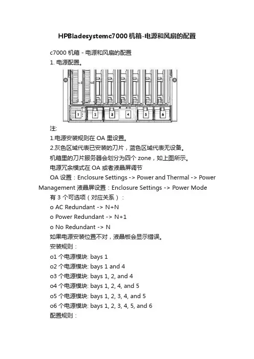
HPBladesystemc7000机箱-电源和风扇的配置c7000 机箱 - 电源和风扇的配置1. 电源配置。
注:1.电源安装规则在OA 里设置。
2.灰色区域代表已安装的刀片,蓝色区域代表无设备。
机箱里的刀片服务器会划分为四个zone,如上图所示。
电源冗余模式在OA 或者液晶屏调节OA设置:Enclosure Settings -> Power and Thermal -> Power Management 液晶屏设置:Enclosure Settings -> Power Mode 有 3 个可选项(对应关系):o AC Redundant -> N+No Power Redundant -> N+1o No Redundant -> N如果电源安装位置不对,液晶板会显示错误。
安装规则:o1个电源模块: bays 1o2个电源模块: bays 1 and 4o3个电源模块: bays 1, 2, and 4o4个电源模块: bays 1, 2, 4, and 5o5个电源模块: bays 1, 2, 3, 4, and 5o6个电源模块: bays 1, 2, 3, 4, 5, and 6配置规则:o1个电源只能是No Redundant供zone 1使用。
o2个电源可以选择No Redundant或者N+1 Redundant或者AC Redundant,如果选择N+1 Redundant或者AC Redundant,则只有一个电源可用,当其中一个电源故障时,另外一个电源可用。
o3个电源可以选择No Redundant或者N+1 Redundant,如果选择N+1 Redundant则当其中一个电源故障时,不会影响供电系统。
o6个电源可以选择No Redundant,这时功率是13500w。
也可以选择N+1 Redundant或者AC Redundant做冗余。

刀片服务器系统硬件安装手册刀片服务器是一种高密度、高效能的服务器系统,它的用户可以灵活地根据需求调整服务器资源,提高数据中心的利用率和性能。
在正式使用刀片服务器系统之前,必须对系统进行硬件安装,下面是一份2000字的刀片服务器系统硬件安装手册。
第一部分:准备工作1.确认机房环境:确保机房具备安装刀片服务器系统的条件,包括足够的通风与散热设备、安全可靠的电源、合适的地面接地等。
2.准备材料和工具:准备好所需的刀片服务器系统硬件包,包括刀片服务器、机架、电源线等。
同时,备齐工具,例如螺丝刀、钳子和网线等。
第二部分:机架安装1.确定机架位置:根据实际需要确定机架的位置,并确保机架与地面垂直。
同时,预留足够的空间以便安装和维修刀片服务器系统。
2.固定机架:使用螺丝将机架固定在地面,确保其稳固可靠。
第三部分:电源连接1.连接电源线:将电源线插入机架顶部的电源插座,确保插头与插座连接牢固。
2.连接UPS:如果系统使用了UPS供电,将UPS的输出线与机架顶部的电源插座连接,确保连接紧固。
第四部分:刀片服务器安装1.打开机架:打开机架的左右侧门,并将门固定在机架两侧的支架上,以便安装刀片服务器。
2.安装滑轨:根据刀片服务器的规格和型号,在机架的前后两个立柱上安装滑轨,确保滑轨长度合适。
3.安装刀片服务器:将刀片服务器轻轻地推入滑轨中,直到刀片服务器底座与滑轨连接。
4.连接电源:将刀片服务器底座底部的电源接口与机架顶部的电源插座连接。
5.连接网络:使用网线将刀片服务器底座的网口与网络交换机连接,确保网络通畅。
6.连接存储:如果系统需要连接存储设备,使用适当的存储接口将刀片服务器底座与存储设备连接,确保数据传输顺畅。
7.安装其他硬件组件:根据需要,安装刀片服务器其他硬件组件,如内存、硬盘等。
第五部分:整理和测试1.整理线缆:将所有线缆整理好,确保不会松动或妨碍通风。
2.测试系统:打开电源,确保系统正常运行。
检查刀片服务器系统的各项功能和性能,例如硬盘、内存、网络接口等。
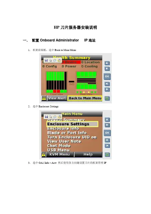
HP刀片服务器安装说明一.配置Onboard Administrator IP地址1.机架前面板,选中Back to Main Menu2.选中Enclosure Settings3.选中OA1 Info – Actv 然后使用各方向键设置刀片的机架管理IP4.点Accept All 保存设置二.设置刀片服务器IP1.IE地址栏输入刀片管理IP 192.168.211.1分别输入OA模块上密码卡片提供的用户名,密码,进入刀片管理主页面。
2.在刀片管理主页面的左侧菜单栏选Enclosure Information——Enclosure Bay IP Addressing在Subnet Mask中输入掩码在右侧图中选中Enabled前的checkbox在地址栏内输入和刀片管理IP同一网段的IP地址分别对应16个刀片服务器。
然后点Apply按钮应用,在Current Address栏中有服务器的位置显示对应的IP地址。
三.操作系统安装1.刀片管理主页面的左侧菜单栏Device Bays下的号码为刀片服务器在机框中的位置号。
2.进入一刀片服务器,点iLO在右侧的Processor Information 下选Integrated Remote Console (IE页面模式)或选Integrated Remote Console Fullscreen(全屏模式),建议选前一项,进入到单个刀片的操作页面。
注:如果没有操作系统,页面为硬件反复自检状态。
3.点击操作页面的VIRTUAL MEDIA 按钮,加载操作系统光盘镜像:点击Image 后的Mount按钮)或加载操作系统光盘:点击盘符后的Monut 按钮。
加载光盘前状态:加载光盘后状态:4.点击操作页面的电源按钮,点中Reset System 按钮,重启对应的大片服务器。
5.服务器重启,自检,光驱启动,进入操作系统安装状态。
与正常的系统安装一样。
操作系统安装结束,启动计算机进入登陆页面(2003为例),点击CAD按钮,选Ctrl -Alt-Del,输入用户名密码,进入操作系统。
c7000如何安装系统
1.请先按附件的图示在刀片机箱前边的小液晶屏,选择main menu给oa配置地址,配置的地址需要和您链接的笔记本或台式机同网段的。
其中附件6-9为设置oa地址方法,需要将oa的地址模式改成static,附件10为设置每个刀片的ilo 地址,需要填subnet mask,最后选择apply。
2. 登陆oa:配置完oa的地址后,将c7000后边oa模块上的oa/ilo接口连入局域网或直连笔记本。
在笔记本上或远程机器上,打开ie浏览器输入oa的ip地址登陆时需要输入用户名和密码,默认的用户名和密码在后边的oa模块上,需要把oa模块拔出来(oa模块可以带电拔)。
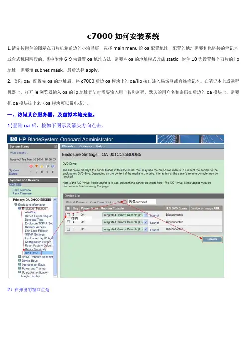
一、访问某台服务器,及虚拟本地光驱。
1)登陆oa后,按如下图示及箭头方向点击。
2)在弹出的窗口点是
在盘符右侧mount,就把本地光驱虚拟给服务器了。
4 ) .插入系统盘或引导盘,按CAD,选择ctrl+alt+del重启服务器,从光盘引导安装系统。
启刀片,从光驱引导
附件:。
0607
0809
10。
HP 刀片服务器安装过程(亲测)
刀片安装实战手册
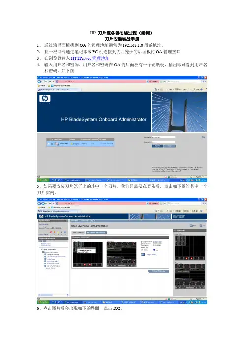
1、通过液晶面板找到OA的管理地址通常为192.168.1.0段的地址。
2、找一根网线通过笔记本或PC机连接到刀片笼子的后面板的OA管理接口
3、在浏览器输入HTTPs://oa管理地址
4、输入用户名和密码、用户名和密码在OA的后面板有一个硬纸板,抽出即可看到用户名
和密码。
如下图
5、如果要安装刀片笼子上的其中一个刀片,我们只需要在登陆后,点击如下图的其中一个刀片实例。
6、点击图片后会出现如下的界面,点击IO2。
以进入安装界面了。
8、我们看到界面的顶部有一个磁盘类型的图标、点击选择我们操作系统的的类型,建议使用ISO,这样速度快。
可选的类型有光盘,磁盘、文件、镜像都可以,根据需要来选择。
9、介质类型选择好之后重新启动服务器就可以进行安装了。
在如下的界面下点击” Web Administration”。
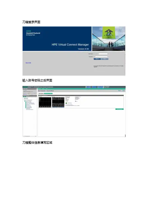
刀箱登录界面
输入账号密码之后界面
刀箱整体信息填写区域
刀箱前控制槽位IP填写
刀箱后控制槽位IP填写
刀箱日志收集出问题需要售后配合分析点击此位置
查看刀箱配置清除VC配置
修改OA账号密码
OA登录密码位数复杂度设置
登录刀片点击想要登录的刀片图标
选择ILO登录模式建议选择最下方选项默认JAVA模式方便快捷需要PC安装java7 或者java8
java登录界面展示此界面空刀片无系统也可以打开,全局管理上下电全部接管
后置VC模块物理映射标识图
单一刀箱具体硬件信息
刀箱后置VC模块配置图解刀箱VC模块登录首页
初始化4部默认下一步即可
配置成功之后登录成功首页
VC模块用户密码相关选项位置
VC模块日志收集位置
引导配置选项包含网络和FC
VC 删除配置查看配置修改VC标记位置删除配置时需关闭所有映射VC配置的刀片
配置网络选项
将配置映射给需要的刀片。
HP刀片服务器操作系统系统安装方法安装了一台HP C7000 16片BL460C,由于HP C7000刀片中心机箱没有光驱设置,每台刀片的面板上都有一个热插拔VGA、KB USB和Mouse USB接口,可以连接到本地的显示器,键盘鼠标上,这和IBM的刀片中心有区别,IBM的刀片中心上带USB接口的键盘鼠标口(外面外形为PS/2),本地还带KVM切换器。
HPC7000我总结了下,安装方法有以下几种:(1)用USB光驱,我没有安装成功因为本地接口只有2个USB接口和VGA接口,1个USB必须连接KB,安装系统时暂不用鼠标.1个USB连接带外置电源的USB 光驱.(2)安装HP Bladesystem 本身带的工具“HP Insight controld Data Center Edition”(8 ILO2 Demo license,30 Day Evaluator),利用RDP中的工具对服务器进行远程安装,在安装中我们可以利用C7000机箱本身带的OA-ILO2的administrator全局用户对所有的刀片进行远程安装、管理等;在安装操作系统中,我们必须将本地的光驱(可以是虚拟光驱)、软驱的盘符通过OA -ILO2端口映射给远程的刀片服务器,进行操作系统的正常安装;(3)利用每台刀片服务器本身带的ILO2 Administrator,用在系统启动时候查到的ILO2拿到的地址,用https://ILO2-IP,Administrator/随机带的Password,或者用F8进入ILO2管理菜单,修改Administrator密码,进行系统登陆后,就可以远程安装和管理操作系统了。
(4)只要安装后一台刀片,我们可以利用本身刀片带的Raid卡功能(必须是Raid 1和windows 2003系统)或者RDP的快速部署,利用热插拔硬盘将所有的刀片进行安装好。
刀片服务器安装指导刀片服务器操作系统安装指导一、安装前准备工作1、刀片服务器机箱前面有一块显示器,见下图,按下“OK”键。
根据显示内容,设置OA1的IP地址,例如192.168.30.63,之后选择“ACCEPT ALL”。
2、将用于远程安装系统的PC与服务器后面的OA管理端口相连接(用网线)。
将PC的IP设成跟OA的IP同一网段,以便能用IE访问OA。
3、安装Java 平台 jre 1.4.2以上版本。
4、确保网络稳定畅通。
5、iLO2 需要使用浏览器进行远程管理操作,浏览器版本需IE 5.5 以上。
6、 solaris 10 需要06年11月以后的版本,最好是07年8月份的版本。
7、需要有阵列卡驱动程序,程序可以刻在光盘上。
8、必须对浏览器进行相关的设置:首先打开IE, 在“工具”菜单里选择“Internet选项”, 见下图然后在弹出的子页面中选择“安全”选项卡, 并点击“自定义级别”按钮, 见下图在弹出的“安全设置”选项卡中, 把Active 的“允许由脚本初始化的窗口…..”由默认的“禁用”改为“启用” , 其他选项均保持默认设置不变, 点击“确定”退出, 见下图, 至此浏览器设置修改完毕。
二、系统安装的过程1、打开IE浏览器, 在地址栏输入OA的IP地址并回车,例如:https://192.168.30.63/。
此时,会弹出一个确认框, 用于确认证书是否有效,选”是”才能进一步操作, 然后就会出现登录界面, 输入账号和密码(本例:Administrator/L0IOVIIG)并点击“Sign In”按钮, 见下图:“Enclosure Bay IP。
”,设置刀片服务器的IP地址,本例如下:3、点击左边框中“Device Bays”下需要安装操作系统的刀片服务器,例如第一台“1.ProLiant BL460c G1”,再点击这台服务器下的iLO,出现图中右边的界面,选择“Web Administration”,进入iLO的管理页面。
HP刀片服务器安装系统教程
一、JS20服务器的开机检查
1.确认服务器的供电是否正常,比如机柜电源是否插好
2.打开机柜前面板,确认HP刀片服务器的状态和灯是否正常
3.检查服务器有没有插入存储磁盘,是否能够正常运行
4.检查服务器上的网口是否可以正常连接
5.开机之前,确认服务器上的内存和CPU是否可以正常运行
二、关于HP刀片服务器安装系统的步骤
1.将安装系统的光盘插入服务器,然后启动服务器,从光驱启动安装系统
2.安装系统开始后,按照提示选择操作系统,然后按提示输入用户名和密码
3.选择安装系统的位置,然后格式化磁盘,并安装系统
4.安装系统结束后,系统会提示您安装驱动程序
5.如果要安装其他软件,可以按照提示安装,最后安装完成后,重新启动系统
6.重新启动系统后,可以根据需要配置系统和网络设置,最后完成HP刀片服务器安装系统的整个工作。
第1章刀片机箱配置HP BladeSystem C系列刀片服务器的基础架构――c7000刀片机箱采用了一系列全新的技术,提供了简化的管理、强大的处理能力、超强的网络带宽,更高效的供电和散热。
1 个c7000刀片机箱可以支持16片半高刀片服务器(BL460c)或者8片全高服务器(BL860c)。
解决方案,最新的SAS和SATA驱动器,实现高效的存储整合。
1.1 刀片机箱IP地址配置使用惠普c-class blade server 的OA 远程管理端口安装设置onboard administrator card(此文中的OA 代表Onboard administrator )。
1.通过机箱前面的小液晶屏设置管理控制器OA的IP地址,先选中enclosure settings ;2.进入enclosure settings 后,设置OA1和OA2的IP地址,设置完成后选Accpect all。
(默认OA1为Active,OA2设置为Standby;实际操作时可根据情况将OA2设置为Active)OA1和OA2的IP地址分配表参见:07服务器相关信息.xls文件《HP刀片服务器OA、ilo2 IP地址分配表》1.2 登录机箱IP,进行刀片设置1.2.1 Administrator用户配置1.通过终端的浏览器输入刀片服务器的OA 口的ip地址:192.168.1.1,进入OA的登录界面,输入机器前方的纸片的出厂OA的用户名和密码登录;2.登录后进入Rack Overview 界面,它把刀片的硬件状态很直观的以图片方式展现,包括设备正反面板图片示意等信息;3.如果是第一次安装刀片服务器机箱,直接进入first timesetup wizard ;4.进入Configuration Management,用它可以快速重载一个以前配制好的OA设置;5.Rack and Enclosure Settings,设置机箱的名称、时间、时区等;6.Administrator Account Setup 设置管理员帐户(Administrator 口令:123);Administrator 是管理员权限,可管理所有的刀片服务器,PINprotection 可以启用(目前未启用)、设置PIN Code 来给刀片服务器前面的液晶屏设置密码;1.2.2 Local Users用户配置用户的建立1、以管理员身份登陆到OA系统,在机框列表中选中要控制的机框。
配置:C7000机箱(标配,2个电源模块、4个风扇)一台,前视图:2P/4P ■后视图C7000机箱一后视图四个电源模块六个风扇兀余OnboardAdministrators3+3 C19巾源线接口热擂拔冗余风BL460 (半高刀片服务器)十台, BL680 (全高刀片服务器)三台, 2个GbE2c 1000M 以太网交换机却■科瘴耳叭存■ M1 个HP Brocade 4/12 SAN SwitchCK> L&J OKJ rwnL沪■* -M *先将电源模块从机箱前面的热插拔电源区域插入,再把风扇从机箱后面上进去。
然后在C7000后视图的“ 8个interconnecte 互连托架”区域里的第一排,插入两个以太网交换机。
在第二排左数第一个插入光纤交换机。
最后上刀片服务器,了解的朋友可以发现,10个半高的跟3个全高的刀片上C7000的机箱,惠普官方说是不可以上的。
半高跟全高混插的话,个数都必需是偶数。
我们先来看下C7000插服务器的大概图解。
如图,横在中间的隔板,是用来支持半高刀片服务器的,一共有4块。
都是可以拆掉的。
拆除方法如下图2■向左推动,打开锁扣3■向内推横隔板到头,将横隔板右边向上提,____________使横隔板脫离右竖隔4.抬高横板,再顺时针方向旋转横隔板肪从机箱牛拆掉一块隔板之后就可以上2个全高的刀片,就是说总共可以上8个全高的。
不拿掉隔板的话,一竖条里可以上4个半高的,总共可以上16个半高的。
现在我这边是10个半高跟3个全高要进行混插。
得拆掉两块横隔板,第一个竖条里放2个全高的,第二个竖条里放1个全高和2个半高的。
现在问题来了。
和全高放一起的这2个半高的,中间的横隔板都已经抽掉了,没支撑物了。
就是说2个半高的得竖着摞一起,但是如果上面的半高的就直接摞另一台上的话,肯定是插不进去的,与后面背板上的插孔是无法对齐的。
所以两个半高的中间必须垫东西,好让上面一台能跟背板的插孔对齐!(额,我是找的一块硬纸板塞里面的,还好客户比较好讲话。