STAR_CCM+_使用手册
- 格式:pdf
- 大小:10.63 MB
- 文档页数:96
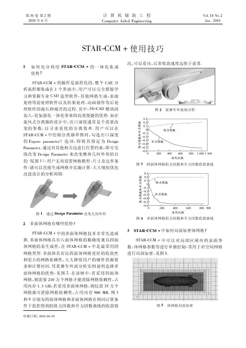
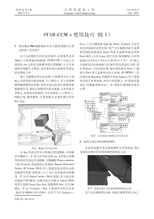
第19卷第2期2010年6月计算机辅助工程Computer Aided EngineeringVol.19No.2Jun.2010STAR-CCM +使用技巧收稿日期:2010-04-281如何充分利用STAR-CCM +的一体化集成优势?STAR-CCM +的操作是流程化的,整个CAE 分析流程都集成在1个界面中,用户可以完全摆脱学习和掌握专业CAD 造型软件,其他网格生成、表面处理等前处理软件以及结果处理、动画制作等后处理软件的漫长和痛苦的过程.其中,3D-CAD 模块的加入,更加强化一体化带来的高效便捷的优势.如在旋风式分离器的设计中,出口深度通常是个需要改变的参数,以寻求更优的分离效率.用户可以在STAR-CCM +中绘制分离器草图时,勾选出口深度的Expose parameter ?选项,即将其指定为Design Parameter.通过对其他相关边进行位置约束,即可实现改变Design Parameter 来改变整体几何外形的目的(见图1),用户无须设置网格模型、尺寸及边界条件,就可以直接生成网格并实施计算,大大缩短优化改进设计的分析周期.图1通过Design Parameter 改变几何外形2多面体网格有哪些优势?STAR-CCM +中的多面体网格技术非常先进成熟.多面体网格具有六面体网格的精确度兼具四面体网格的易生成性,在STAR-CCM +中是最常用的网格类型.多面体具有比四面体网格更好的收敛性和更小的网格依赖性,大大降低用户的硬件资源要求和计算时间.用某赛车外流分析实例说明选择多面体网格的优势,见图2.在该例中,若采用四面体网格,则需要210万个网格才能消除网格依赖性,占用内存1.3GB ;若采用多面体网格,则仅需35万个网格就可消除网格依赖性,占用内存900MB.图3和4分别为四面体网格和多面体网格在相同计算条件下监控得到的阻力因数和升力因数曲线的收敛情况,可以看出,后者收敛速度远快于前者.图2某赛车外流场分析图3四面体网格阻力因数和升力因数收敛曲线图4多面体网格阻力因数和升力因数收敛曲线3STAR-CCM +中如何局部加密体网格?STAR-CCM +中可以对局部区域内的表面参数、体网格参数等进行单独控制,常用于对空间网格进行局部加密,见图5.图5体网格局部加密加密过程如下:首先,在管理树Tools>Volume Shapes上点击右键,在New Shape下选择要加密区域的形状,如长方体(Brick)、锥体(Cone)、柱体(Cylinder)和球体(Sphere)等.进入编辑状态后,用鼠标拖动或坐标输入的方式确定加密区域的大小范围,并点击Create建立,在Volume Shapes节点下会生成1个子节点(如Brick1),即新建的区域.然后,右键点击Continua>Mesh1>Volumetric Controls选择New新建,出现子节点Volumetric Control1,在其属性窗口中将Shapes项选入前面新建的加密区域Brick1.在Volumetric Control1>Mesh Conditions中选择与体网格相关的Mesher(如Polyhedral Mesher,Trimmer等)并在其属性窗口中将Customize…项勾选.在Volumetric Control1节点下会生成Mesh Values子节点,修改其参数可以单独控制加密区域的体网格尺寸,实现局部加密的目的.4STAR-CCM+中如何处理无厚度表面生成双面边界层网格?在生成体网格时,如果遇到空间中的无厚度表面,按下述方法处理可解决拓扑封闭问题,并可在表面两侧生成质量很高的边界层网格(图6).图6无厚度表面边界层网格右键点击Regions>Region1>Boundaries节点下的空间面名称,选择Convert to Interface(s),将此无厚度面转换成Interface.修改Interfaces节点下此无厚度面interface的属性,将Type选择为Baffle.在该Interface节点下的Mesh Conditions下Interface Prism Layer Option属性打勾选中.从Interface节点向双面产生边界层,默认的边界层参数是在Mesh Continua里设定的全局参数.如果需要定义向双面生长的不同参数,需要修改Regions>Region1>Boundaries里,对应于生成Interface节点的2个Boundary节点的Mesh Conditions里的Customize Prism Mesh参数来实现.(待续)(本文由西迪阿特信息科技(上海)有限公司技术部供稿.读者若对STAR-CCM+产品感兴趣,可以联系support@.檿檿檿檿檿檿檿檿檿檿檿檿檿檿檿檿檿檿檿檿檿檿檿檿檿檿檿檿檿檿檿檿檿檿檿檿檿檿檿檿檿檿檿檿檿檿)(上接第97页)5在MSC Patran中如何撤销已选择的单元或节点?当模型较大且选择较多单元或节点时,如果使用Backspace键撤销选择会浪费较多时间,但采用以下2种方法可以快速撤销已选单元:(1)双击选项框;(2)充分利用快捷键Tab,同时按下Tab键和Shift键.通过这2种方法就可以1次选中要删除的所有单元或节点,然后1次性删除即可.6在LS-DYNA中简化积分时怎样避免或减小沙漏?在显式动力分析中采用简化积分可以极大节省数据存储量和运算次数,并且在大变形分析中更加适用.但是,简化积分会出现沙漏(零能模式),因此需要有效控制分析中可能出现的沙漏变形,控制沙漏的方法有:(1)尽可能使用均匀的网格划分;(2)尽量避免单点载荷;(3)由于全积分单元不会出现沙漏,用全积分单元定义模型的部分或全部以减小沙漏;(4)全局增加模型的体积黏性.7在HyperMesh中如何改变壳单元的方向?前处理有限元软件HyperMesh划分好面网格后,可能会存在同一个面上单元方向不一致的情况(颜色光亮度有一定差异),在后续施加面载荷或定义单面接触时需要改变壳单元的方向,使同一面上壳单元的方向一致.修改方法为:(1)在主菜单区选择Tools->normals;(2)通过组件或直接选择同一面上的单元,并采用color display normals显示方式,点击display normals,由此直观地通过蓝红2种颜色的单元将不同方向的单元区分开来;(3)在orientation中选择面上的1个单元,点击adjust normals,则所在面上壳单元的方向都改为orientation 中所选单元的方向.(摘自同济大学郑百林教授《CAE操作技能与实践》课程讲义.)99第2期STAR-CCM+使用技巧。
STARCCM基础培训教程STARCCM是一款涉及CFD(计算流体力学)模拟工作的软件,它可以在不同行业中用于解决各种流体流动问题,如航空航天、汽车制造、水利工程等领域。
该软件的应用得到了广泛认可,并在各个行业中拥有广泛的用户群体。
为使用户能够更好地使用STARCCM,建议进行基础培训与学习,以便熟练掌握其各种功能和优点。
下面详细介绍STARCCM基础培训教程。
一、STARCCM简介STARCCM是CD-adapco公司开发的一款CFD商业软件,目标是为流体力学分析和优化提供强大的计算工具,涵盖了从几何设计到流体动力学的全部过程。
二、基础操作界面开始使用STARCCM软件时,首先介绍基础操作界面的结构。
而在软件界面的左侧是操作界面,最右侧是3D工具栏,包括模型创建、矢量图表、芯子提取工具等。
右上角的工作区域包括剖面图、曲线、矢量图和Tecplot文件等显示方式。
三、STARCCM的模型无论在哪个行业中,模型是创建流体流动的基础,在STARCCM软件中,创建复杂的流动图是相当困难的,因此在初学者的学习过程中,需要重点了解模型是如何建立的。
一般来说,可以手动建立模型,或者利用静态、动态网格技术,转移相应模型数据。
四、网格生成技术网格的生成是实现精细流体流动分析的重要步骤,因此不同的网格类别会对流动计算的结果产生不同的影响。
根据所需的精度和时间,根据不同的网格技术建立相应流体流动分析计算。
五、流动计算流动计算是了解和掌握流动分析研究目的的基础。
在STARCCM中,流动计算是目标计算的核心部分,其效率和精度直接决定了计算的属性。
STARCCM软件提供了各种流体流动分析模式的支持,如稳定流、不稳定流和湍流模式等。
六、后处理流动计算后处理是流动分析阶段的最后一步,它可以将流动计算的结果显示在2D或3D模型中,并对其进行编辑和可视化。
后处理还包括实体解动画、热画像、粒子轨迹等功能,并提供给广泛的用户来探索流动分析的复杂性。
STARCCM基础培训教程引言第一部分:软件安装和启动1.1软件安装在进行STARCCM基础培训之前,需要安装软件。
请访问官方网站最新版本的STARCCM安装包。
根据操作系统的要求,选择相应的安装包进行。
1.2软件启动安装完成后,双击桌面上的STARCCM图标或从开始菜单中找到STARCCM并启动。
启动后,将显示软件的欢迎界面。
第二部分:基本操作和界面介绍2.1操作界面STARCCM的操作界面主要包括菜单栏、工具栏、浏览器、视图和状态栏等部分。
菜单栏位于界面的顶部,提供了各种功能和选项。
工具栏位于菜单栏下方,包含了一些常用的工具和按钮。
浏览器位于左侧,用于显示和管理场景中的对象。
视图位于中央,用于显示模型的图形界面。
状态栏位于底部,显示了一些关于当前操作的信息。
2.2基本操作在STARCCM中,基本操作包括创建模型、设置边界条件、划分网格、求解和后处理等。
下面将简要介绍这些操作的基本步骤。
2.2.1创建模型在菜单栏中选择“File”->“New”创建一个新的模型。
在弹出的对话框中,可以选择模型的类型和单位制。
然后,根据需要创建几何形状,可以使用内置的几何创建工具或导入外部CAD模型。
2.2.2设置边界条件创建模型后,需要设置边界条件。
在浏览器中,找到相应的边界条件选项,并进行设置。
例如,可以设置进口速度、出口压力、壁面粗糙度等。
2.2.3划分网格设置边界条件后,需要对模型进行网格划分。
在菜单栏中选择“Mesh”->“CreateMesh”进行网格划分。
在弹出的对话框中,可以选择网格类型和网格参数。
然后,“Generate”按钮网格。
2.2.4求解网格划分完成后,可以进行求解。
在菜单栏中选择“Simulation”->“Run”进行求解。
在弹出的对话框中,可以选择求解器类型和求解参数。
然后,“Start”按钮开始求解。
2.2.5后处理求解完成后,可以进行后处理。
在菜单栏中选择“Results”->“Post-processing”进行后处理。
starccm宏录制流程English Answer:How to Record Macros in STAR-CCM+。
STAR-CCM+ macros allow you to automate repetitive tasks and streamline your workflow. Here's a step-by-step guideon how to record macros in STAR-CCM+:1. Open the Macro Recorder: Click on "Tools" -> "Macro Tools" -> "Macro Recorder" to open the macro recorder panel.2. Start Recording: Click on the "Record" button (red circle) to start recording your macro.3. Perform Actions: Carry out the actions that you want to record in the macro, such as creating a new scene, modifying mesh properties, or generating reports.4. Stop Recording: Once you have finished recording theactions, click on the "Stop" button (black square) to stop the recording.5. Save Macro: Enter a name for your macro in the "Macro Name" field and click on the "Save" button (disk icon) to save the macro.Additional Tips:Use descriptive names for your macros to make them easy to identify later.Macros can be parameterized using macro variables, which allows you to reuse the macro with different inputs.You can edit the recorded macro script to customize or optimize it further.Chinese Answer:STAR-CCM+ 宏命令录制流程。
starccm网格重构操作流程英文回答:The process of mesh refinement in STAR-CCM+ involves several steps to ensure that the mesh accurately represents the geometry and captures the flow physics. Here is a general outline of the workflow:1. Pre-processing: Before starting the mesh refinement process, it is important to have a well-prepared geometry. This includes removing any unnecessary features, repairing any gaps or overlaps, and ensuring that the geometry is watertight. Once the geometry is ready, it can be imported into STAR-CCM+.2. Initial mesh generation: The next step is to generate an initial mesh using the default settings in STAR-CCM+. This initial mesh may not be suitable for accurate simulations, but it provides a starting point for refinement.3. Mesh quality assessment: Once the initial mesh is generated, it is important to assess its quality. STAR-CCM+ provides various tools and metrics to evaluate the mesh quality, such as skewness, aspect ratio, and orthogonality. These metrics help identify areas of the mesh that require refinement.4. Local mesh refinement: Based on the mesh quality assessment, local mesh refinement can be performed in STAR-CCM+. This involves adding more mesh cells in areas where the mesh quality is poor or where high resolution is required. Different refinement techniques, such as surface refinement, volume refinement, and inflation layers, can be used to improve the mesh quality in specific regions of interest.5. Global mesh refinement: In addition to local refinement, global mesh refinement can also be applied to improve the overall mesh quality. This involves increasing the mesh density throughout the domain, which helps capture the flow physics more accurately. However, it is importantto balance the mesh density with computational resources to avoid excessive computational cost.6. Iterative refinement: Mesh refinement is aniterative process, and it may require multiple cycles of refinement and assessment to achieve the desired mesh quality. After each refinement step, the mesh quality should be reassessed to ensure that the desired improvement has been achieved.7. Post-processing: Once the desired mesh quality is achieved, post-processing can be performed in STAR-CCM+. This includes visualizing the mesh, extracting relevant data, and analyzing the simulation results.In summary, the process of mesh refinement in STAR-CCM+ involves pre-processing, initial mesh generation, mesh quality assessment, local and global mesh refinement, iterative refinement, and post-processing. Each step is crucial in ensuring an accurate and reliable mesh for simulation.中文回答:在STAR-CCM+中进行网格重构的过程涉及多个步骤,以确保网格准确地表示几何形状并捕捉流动物理。
Simcenter STAR-CCM+是一个功能强大的计算流体动力学(CFD)软件,用于模拟和分析流体流动、传热和流体-结构相互作用等问题。
以下是一个使用Simcenter STAR-CCM+进行流体动力学模拟的简单例程:启动STAR-CCM+并创建新模拟:打开Simcenter STAR-CCM+软件。
在主界面上选择“File”>“New Simulation”来创建一个新的模拟。
导入几何:在菜单栏中选择“File”>“Import”>“Import Surface Mesh”。
导航到包含要导入的几何文件的文件夹,并选择该文件。
点击“Open”以导入几何。
创建区域和边界:在“Simulation Tree”中,右键单击“Continua”并选择“Create New Part”。
为新部分命名并选择适当的区域类型(例如,流体或固体)。
使用工具栏上的工具创建边界条件,例如入口、出口和壁面。
设置物理模型:在“Simulation Tree”中,右键单击“Physics”并选择适当的物理模型(例如,三维、隐式非稳态、多相等)。
根据需要调整物理模型的参数和属性。
定义网格:在“Simulation Tree”中,右键单击“Mesh”并选择“Generate Mesh”。
选择适当的网格生成器并调整网格参数,以获得所需的网格质量和分辨率。
设置求解器参数:在“Simulation Tree”中,右键单击“Solver”并选择适当的求解器(例如,压力基或密度基)。
调整求解器参数,例如时间步长、收敛准则等。
运行模拟:在菜单栏中选择“Solve”>“Run”来开始模拟。
监视模拟进度并等待其完成。
后处理和结果可视化:在模拟完成后,使用Simcenter STAR-CCM+的后处理工具对结果进行可视化和分析。
可以创建图表、动画和报告来展示模拟结果。
保存和导出:在完成所有分析和可视化后,保存模拟文件。
STAR CCM+_使用手册STAR CCM+ 使用手册1:简介1.1 STAR CCM+ 是什么1.2 STAR CCM+ 的特点和优势1.3 适用领域和应用场景2:安装和设置2.1 系统要求2.2 和安装2.3 许可证配置3:用户界面3.1 主界面概览3.2 工作区和视图操作3.3 创建新项目3.4 导入和导出文件4:几何建模4.1 创建基本几何体4.2 修改和编辑几何模型4.3 网格4.4 网格质量控制5:物理模型5.1 流体物理模型5.1.1 流场设置5.1.2 流体材料定义和属性 5.1.3 边界条件设置5.2 固体物理模型5.2.1 固体材料定义和属性 5.2.2 边界条件设置5.3 热传导模型5.4 化学反应模型5.5 多相流模型5.6 其他物理模型的设置6:求解和结果分析6.1 求解设置6.2 后处理选项6.3 结果导出和可视化6.4 结果数据分析7:高级功能和选项7.1 自定义工作流程7.2 脚本编程7.3 并行计算设置7.4 批处理操作附件:附件A:STAR CCM+ 示例文件附件B:帮助文档和教程参考法律名词及注释:1:许可证配置:指根据法律规定,将软件合法授权给特定用户或单位使用的配置过程。
2:几何建模:通过绘图、编辑和修改来创建和操纵几何模型的过程。
3:流体物理模型:描述流体(如气体和液体)运动规律和特性的数学模型。
4:固体物理模型:描述固体物体(如零件、结构等)的力学行为和材料特性的数学模型。
5:自定义工作流程:根据用户需求,构建和定制特定的流程和操作步骤。
6:脚本编程:使用特定的编程语言对软件进行自动化控制和操作的过程。
star ccm发动机舱热管理计算设置概述说明1. 引言1.1 概述在现代航空领域中,发动机舱热管理对于飞机的安全性和性能至关重要。
通过科学合理地设置热管理计算参数,可以有效控制发动机舱温度,提高发动机的工作效率和寿命,并最大程度地减少风险因素。
Star CCM是一种广泛应用于流体力学仿真的软件工具,该工具可用于模拟并优化各种复杂系统,包括飞机发动机舱的热管理。
1.2 文章结构本文将首先介绍Star CCM这一流体力学仿真软件工具的基本概念和原理(第2节)。
接下来,我们将详细讨论发动机舱热管理计算设置中的关键要点(第3节)。
最后,在结论部分(第4节),我们将总结主要观点,并探讨发动机舱热管理计算设置所带来的意义和影响。
1.3 目的本文的目的是向读者介绍如何使用Star CCM软件进行发动机舱热管理计算设置。
通过了解此过程中需要注意和考虑的关键要点,读者将能够掌握如何在实际应用中进行热管理计算设置,并明白这一过程对于提高发动机效率和延长发动机寿命的重要性。
同时,本文还将探讨热管理计算设置的意义和影响,以便读者能够更好地理解其在航空领域中的应用前景。
2. 正文:2.1 Star CCM介绍Star CCM是一款基于计算流体力学(Computational Fluid Dynamics, CFD)的软件,可用于模拟和分析各种流体动力学问题。
它提供了强大的求解器和可视化工具,能够准确地解决复杂的流动、传热和传质现象。
2.2 发动机舱热管理计算设置概述发动机舱热管理计算设置是指在使用Star CCM进行发动机舱热管理计算时所需的初始条件、边界条件和参数设置。
通过合理设置这些参数,可以准确地模拟发动机舱内的温度场分布以及热量传递情况,为航空发动机的设计和优化提供依据。
2.3 热管理要点1在发动机舱热管理计算中,首先需要确定发动机表面温度分布。
这可以通过实测数据或者其他已知条件来得到。
对于未知区域,则需要根据经验或者推测进行估计。
StarCam使用说明书STARCAM绘图加工简明说明书STARCAM是数控机支持软件。
STARCAM含有三个模块,1、STARCAM绘图加工模块;StarNEST 套料输出模块; StarPlot仿真模块。
一个简单实用于数控设备的图形绘图软件,具有数控专业特点。
STARCAM绘图加工模块是一个支持数控加工集图形绘制模块,用户可利用本模块完成零件的绘制、编辑、CAD、CAM转换、压缩、标记文字及标记尺寸、轮廓缩放和图库管理等操作,也可将StarNEST输出的 CAM格式的套料文件进行再处理,并可生成零件的NC加工代码。
STARCAM与CAD不同,是个指令+鼠标绘图系统,绘图工具比较简单。
一、文件菜单,与多数软件相同。
1、打开文件:只能打开 CAM图形文件。
但 STARCAM可以导入 CAD文件进行编辑修改,以 CAM文件格式存储。
2、利用导入可以打开标准 CAD的 DWG、矢量格式DXF 图形文件和数据转换 IGES 格式文件。
导出只能形成 DWG、DXF文件。
3、支持打印实体图形列表和屏幕打印。
4、零件数据是图形文件的简单说明。
二、编辑菜单:1、最实用的是“智能修剪”。
可以说优于CAD的修剪工具。
2、还有缩放和编辑图形功能。
编辑点位置、线长度和实体线延伸等。
由于是指令点方式,也优于 CAD的拉伸的精度,用起来较慢。
三、显示:1、最有特色的是显示设置,可以自动标注尺寸。
2、可按 DXF图层默认层颜色显示。
四、绘图:因为是指令 +鼠标式绘图方式,与 CAD略有不同。
真正用起来还是比较快(一定要习惯这种方式。
)1、画直线:有屏幕点、坐标点等。
可以理解屏幕点就是用鼠标点击形成;坐标点是指令框输入。
其它雷同。
总之,用熟后会感觉比 CAD还快,只是没有随意性,在点受约束感。
2、绘制圆弧和平行线有方向性,需要鼠标点击来确定。
其它雷同。
五、“构件”菜单:是一个编辑项工具。
1 、值得说明的是,多数指令是针对指定点中心现的(如开槽)角过渡等。
Siemens Digital Industries SoftwareSimcenter STAR-CCM+ Web ViewerUser Guide/simcenterccmVersion 2206You can view exported 3D files of Simcenter STAR-CCM+ plots and three-dimensional scenes (.sce files) through your web browser. This capability lets you view post-processed data from Simcenter STAR-CCM+ simulations without having any special software installed.Simcenter STAR-CCM+ Web Viewer renders scene files locally in the browser. The files are not uploaded to any web server at any stage in the process.For scenes, you can manipulate the view using zoom, pan, and rotate. However, more features are available with the standalone viewer, Simcenter STAR-CCM+ Viewer.Contents:Using Simcenter STAR-CCM+ Web Viewer to Interact with ScenesSimcenter STAR-CCM+ Web Viewer ReferenceSupported Platforms and BrowsersYou can view exported 3D files of Simcenter STAR-CCM+ plots and three-dimensional scenes (.sce files) through your web browser.If you are a Simcenter STAR-CCM+ user, you can export a scene to an external file. All post-processing must be prepared in the Simcenter STAR-CCM+ client before the scene or plot is exported to the scene file. You cannot create or modify plots or scenes in the web viewer itself. For details, see Exporting an Interactive 3D Scene to Simcenter STAR-CCM+ Viewer or VRML in the Simcenter STAR-CCM+ User Guide.You can load the scene (.sce) files on your network or local drive. Make sure you are using a compatible platform and web browser. See Simcenter STAR-CCM+ Web Viewer Supported Platforms and Browsers for a list. You can manipulate a scene or plot view (for example zoom or pan) as you would in a standardSimcenter STAR-CCM+ client. However, you cannot perform certain tasks with scene files that are possible in the standalone Simcenter STAR-CCM+ Viewer client. These include saving scene images, animating scenes, and activating advanced rendering.1.In your web browser, go to the following web address: https:///starccmviewer/Simcenter STAR-CCM+ Web Viewer appears with its initial splash screen.2.To access a scene file, near the upper left corner of the page, click (Open Scene File).3.In the Open dialog, navigate to the scene file and click Open.The scene or plot display appears in your browser.If your scene file is a frameset (a file containing multiple scenes and/or plots) then the Scene/Plot selection panel appears at the left of the display with a list of contents. Click any of the listings to switch to that scene or plot. Alternatively, press <Tab> or <Shift>+<Tab> to move down or up the list, respectively.To toggle the visibility of the selection panel, click (List Scenes).Once the scene or plot appears, the techniques for examining a scene in Simcenter STAR-CCM+ Web Viewer are similar to some of the interaction with the display in Simcenter STAR-CCM+ Viewer. However,Simcenter STAR-CCM+ Web Viewer interaction is limited to the actions listed in the next step.4.With the scene file open, manipulate a scene or plot view:Panning To pan the image in the visualization display, hold down the right mouse buttonand drag the mouse in the direction where you want to move the object.The image appears to change its view angle as you pan.Rolling To roll the scene, hold down the <Ctrl> key, and click and drag the mouseupward or downward.Using the <Ctrl> key rotates the object along an axis perpendicular to yourscreen.Rotating To rotate, choose a point on or near the object in the visualization display, and click and drag (holding down the left mouse button) from that point.This technique rotates the object around the axis perpendicular to the direction ofyour drag. You set the location of the axis when you choose a point to beginclicking and dragging.Simcenter STAR-CCM+ Web Viewer uses a point on a part to rotate. If you select apoint somewhere other than on a part, Simcenter STAR-CCM+ Web Viewer uses thedepth to that last point; the depth is normal to the view plane.The scene can be rotated around various axes, vertical, horizontal, or arbitrary,depending on the direction you move the mouse.Zooming There are two ways to zoom with the mouse:◦Choosing a focal point:Choose a point inside the display, then click and drag downward using themiddle mouse button. This action brings your view closer to that point.Moving the mouse straight up has the opposite effect.◦Using the mouse wheel:Turning the mouse wheel toward you brings your view closer to thevisualization display; the opposite wheel movement takes your view fartheraway.The mouse pointer must be within the visualization display for this operation towork. Its particular position within the display determines the direction of thistype of zooming.Note:Vectors in Simcenter STAR-CCM+ Web Viewer look as they did when youexported the scene; the vector lengths do not update when you zoom in.This is due to the fact that exported vector scenes do not retain all vectordata.5.To restore the view so that the entire model is centered in the display, click (Reset View).6.To return to the main Simcenter STAR-CCM+ Web Viewer screen, click (Home).Simcenter STAR-CCM+ Web Viewer lets you view post-processed data from Simcenter STAR-CCM+ simulations without having any special software installed.The following table lists the actions that are available in Simcenter STAR-CCM+ Web Viewer.(Home)Returns to the main screen of Simcenter STAR-CCM+ Web Viewer.(Open Scene File)Opens a standard dialog for navigating to the scene (.sce) file. Simcenter STAR-CCM+ Web Viewer renders scene files locally in the browser. The files are not uploaded to any web server at any stage in the process.(List Scenes)Opens a navigable sidebar that lists all scene and plot images that are included in the scene file.(Reset View), also <R>Restores the view to a zoom factor such that the model is centered in the display. The view angle is unchanged. Pressing <R> has the same effect.Use this function if the model has somehow zoomed or panned to such a position that you can no longer see it on the display.(Save as Image)Allows you to save a snapshot of the scene to an image file using the properties dialog.(Trimetric View)Switches to a trimetric, or diagonal, view.(Front/Back View), also <F>On the first click, switches to the front view. On the second click, switches to the back view. Pressing <F> has the same effect.(Left/Right View), also <S>On the first click, switches to the left view. On the second click, switches to the right view. Pressing <S> has the same effect.(Top/Bottom View), also <T>On the first click, switches to the top view. On the second click, switches to the bottom view. Pressing <T> has the same effect.(Help)Launches Simcenter STAR-CCM+ Web Viewer Help.The following web browsers, on the following platforms, are supported for Simcenter STAR-CCM+ Web Viewer. Supported in this context means that some testing has been performed or compatibility is expected.© 2022 SiemensThis software and related documentation are proprietary and confidential to Siemens. A list of relevant Siemens trademarks can be found here. Other trademarks belong to their respective owners.。
starccm操作规程操作规程是为了确保操作过程的安全和规范性,下面是关于STAR-CCM+(流体动力学/分析软件)常见的操作规程,供参考:一、开启 STAR-CCM+ 软件1.先检查计算机是否已安装了STAR-CCM+ 软件,并确保已登录正确的账号。
2.打开软件所在的文件夹,找到并双击“starccm+”图标,启动软件。
二、新建项目1.在STAR-CCM+ 软件界面左上方的菜单栏中,选择“File”->“New”,弹出“New Simulation”对话框。
2.在“Simulation Type”下拉菜单中选择适当的模型类型,如流体流动、传热、湍流等。
3.在“Simulation name”中输入项目的名称。
4.点击“OK”按钮,创建新的项目。
三、导入模型1.在STAR-CCM+ 软件界面左侧的“Outline Tree”窗格中,双击项目名称以展开项目。
2.右键点击“Geometry”文件夹,选择“Import CAD Files”选项。
3.在弹出的对话框中选择要导入的CAD 文件,并指定导入选项(如尺寸、坐标系等)。
4.点击“OK”按钮,导入模型。
四、设定边界条件1.在“Outline Tree”窗格中,展开“Boundary Conditions”文件夹,选择要设定边界条件的区域。
2.右键点击所选区域,选择“Create/Edit Boundary Conditions”选项。
3.根据实际情况,在弹出的对话框中设置边界条件,如速度、温度等。
4.点击“OK”按钮,保存设定。
五、定义求解器设置1.在“Outline Tree”窗格中,展开“Physics Continua”文件夹,双击“Physics Models”文件夹。
2.右键点击所选物理模型,选择“Edit Physics Model”选项。
3.在弹出的对话框中,根据实际情况设定模型参数,如粘性系数、湍流模型等。
4.点击“OK”按钮,保存设定。