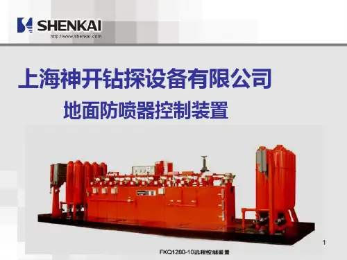
koomy unit 封井器远程控制台说明书
- 格式:pdf
- 大小:3.15 MB
- 文档页数:65

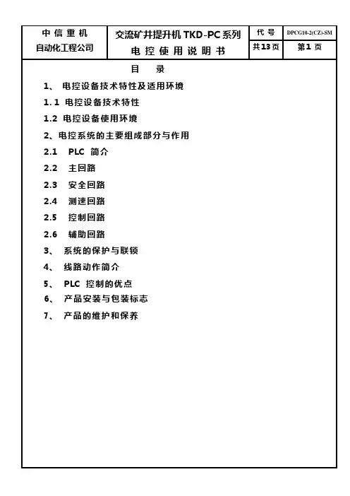
目录1、电控设备技术特性及适用环境1.1 电控设备技术特性1.2 电控设备使用环境2、电控系统的主要组成部分与作用2.1 PLC 简介2.2 主回路2.3 安全回路2.4 测速回路2.5 控制回路2.6 辅助回路3、系统的保护与联锁4、线路动作简介5、PLC 控制的优点6、产品安装与包装标志7、产品的维护和保养1、电控设备技术特性及适用环境1.1 电控设备技术特性本电控设备适用于单绳牌坊式提升机,包括单筒、双筒,单水平、多水平(最多不换层8水平,换层4水平),也可适用于多绳监控器或牌坊式,采用具有远程智能站的操作台、含数字式深度指示的提升机。
1.2电控设备使用环境(1).环境温度不高于40℃、不低于-5℃。
(2).相对湿度不超过85% (+25℃)。
(3).没有导电尘埃及对金属和绝缘有破坏作用的气体。
(4).没有剧烈的振动和颠簸。
(5).不必防爆的地方。
(6).采取措施后能满足上述条件的场所。
2、电控系统的主要组成部分与作用2.1.PLC 简介PLC系统由一个主PLC系统(A)和一个从PLC系统(B)组成。
主PLC系统放在主令柜里,它由一个基本单元(FX2N-80MR)、一个扩展输入模块(FX2N-16EX),二个功能模块(FX2N-4AD,FX2N-2DA)及一个通讯模块(FX2N-485-BD)组成。
从 PLC系统放在操作台里,它由一个基本单元(FX2N-80MR)、一个扩展输入模块(FX2N-16EX),二个扩展输出模块(FX2N-16EYT)及一个通讯模块(FX2N-485-BD)组成。
①.数字量模块:FX2N-80MR,FX2N-48MR,FX2N-16EX用于开关量信号的输入和输出。
输入/输出点数分别为:40/40,24/24,16/0。
②.模拟量模块:FX2N-2DA为模拟量输出模块,用于两路模拟量信号的输出。
FX2N-4AD为模拟量输入模块,用于四路模拟量信号的输入。
2.1.1安装注意事项:①.不宜安装在含有灰尘、油烟、导电性粉尘、腐蚀性及可燃性气体的场所。

Product ManualName : Rimikon IP CONTROLLERModel : RIM-IPC1275 Leeds ave Suite 800 Ottawa , Ont Canada K1B 3W2 1877-470-7480Product Info∙This IP Controller is designed for Rimikon's Extra Low Voltage LED Products.∙This unit is IP addressable or WIFI and can be used with the Rimikon Android and IOS App.∙The remote control distance can reach up to 50 meters indoor and upp to 100 meters outdoor.Item Model DescriptionRimikon IP Controller RIM-IPC Used to control Rimikon's LED Lighting products1. Rimikon IP Controller Instruction1.Install Rimikon LED IP Controller APPFirst go to Google play or i tune store ,Search for the Rimikon.Download and install the Free Rimikon App.2.Connecting your devise ( mobile or tablet) with theRimikon IP Controller.1. Do Not Plug the RIMIKON power supply into the electrical outlet till allsteps are done .2. Connect the Rimikon power supply low voltage output to the IP Controller .( see figure 1)3. From the IP Controller connect Rimikon’s LED lights.4. Connect the Rimikon power supply AC input into the electrical socket oncesteps 2 and 3 are completed. (see figure 1.)5. Go to your device settings and turn on WiFi then select the SSID –LEDnet.xxxxxxxx and use password 88888888 (see figure 2 )6. Lauch the Rimikon App7. Once the scan is complete , select the Rimikon IP Controller in the devicelist. (see figure 3)1) 2) 3)3.Renaming the IP Controller in your device list1. Launch the Rimikon App2. Scan for the Rimikon IP Controller ,once scan is complete use a long presson the Rimikon IP Controller name and change the name .see figure 3 and 43) 4)4 .How to change the SSID and password1. Launch the Rimikon App2. Scan for the Rimikon IP Controller, once scan is complete select the RimikonIP Controller in the device list and select settings, then select device settings ,select change under LED device security settings. (See figure 5.6.7.8.)5) 6) 7) 8)5.Link the Rimikon IP Controller to your Router.1. Launch the Rimikon App2. Scan for the Rimikon IP Controller, once scan is completed select theRimikon IP Controller in the device list , select settings, select device settings,select Link to wireless router in network mode. (see figure 5.6.7.9.)5) 6) 7) 9)6.How to find your Mac address for hard wire connections.1. Launch the Rimikon App2. Scan for the Rimikon IP Controller, once scan is completed select theRimikon IP Controller in the device list, select settings , select device settings and right the Mac address .see figure 5,6,73. Once you have fond the Mac address ,Disconnect power to the Rimikon IPController and place the switch in the network position on the front of theRimikon IP Controller.4. Plug the Ethernet cable from the Router into the RJ-45 connection on thefront of the Rimikon IP Controller.5. Connect the power to the Rimikon IP Controller .6. Connect your device using your home WiFi network and launch the RimikonApp, select the Rimikon IP Controller in the device list and select settings ,select device settings and confirm the Mac / IP address.5) 6) 7)7. Software Operating (Single Color ) How to use Single color mode.1) Load Rimikon App on your device .2) Brightness: you can change it from 0 to 100%3) Power button : On and OffSPEC SHEETItem Model DescriptionRimikon IP Controller RIM-IPC Used to control Rimikon's LED Lighting productsSpecs :Item Version : Single Color version 1.01. Working Voltage DC7.5-24V2. Output current : 4Amp3. Connecting method: Terminal4. Dimension: L11cm*W 7cm*H 4cm5. Remote Distance : 50 meters indoor ,100 meters outdoor6. Software: Android ,IOS, Version 1.0 with WIFI7. Receiver sensitivity: 802.11d DSSS(-5DBM) 802.11d CCK 802.11gOFDM(-15dBm)8. Connection : V+ V- for LED lights, V+V- or 2.5mm jack for Power supply.9. Reset button ( on front of unit) 5 secound hold for factory reset10. Wifi SSID for connection is LEDnetXXXXXXXX passsword:888888881275 Leeds ave Suite 800 Ottawa ,Ont Canada K1B 3W2 1877-470-7480。

皮带操作台控制系统使用说明书一、操作台功能概述本系统采用触摸屏和可编程序控制器相结合,实现主井皮带电机的手动与自动起动。
手动时,可使用操作台上的手动按钮来控制主井电机、液力耦合器的执行器及制动器的起停,自动时可使用操作台上的自动旋钮来实现电机及其它设备的控制,自动实现电流平衡、起动预警,及所有皮带保护,设备故障,勺杆推拉的联机控制,且操作台上设置了打点、送话功能,沿线双向送话,可显示电流、电压、带速、油温,以及设备开停时间,故障时间及故障时的电流等。
可显示皮带保护的各种故障地址。
系统主要采用三菱PLC可编程控制器,EVEIW触摸屏,模拟输入模块,数显表。
系统功能概述:1、手/自动切换2、手,自动开停主电机、勺杆、制动器3、紧急停车4、开车预警5、送话及打点6、故障复位7、电机运行、停车及故障状态指示8、电机电流、电压、油温及带速显示9、皮带拉绳、跑偏、打滑保护及地址显示10、皮带运行时间及设备开停故障时间显示二、操作说明★(1)手动运行开车:高压柜合闸,操作台右下角电源指示灯亮→将操作台左边万转打到“2”上开2#冷却泵→将手动/自动开关打到手动位置→按下手动预警按钮→按下1#电机启动按钮→8秒后按下2#电机启动按钮→打开制动旋钮→同时按下1#和2#勺杆拉按钮,按2秒停4秒直到电机开到预设的速度。
当皮带开起来后,时刻观察1#和2#电机电流的平横。
当其中一个电流过小时可单独点动拉其勺杆或点动推另一勺杆。
停车:按下打点按钮→同时推1#、2#勺杆直到其推到指示灯亮→停1#、2#电机→手动关制动器。
急停:按下急停按钮即可全部停车。
★(2)自动运行开车:高压柜合闸,操作台右下角电源指示灯亮→将操作台左边万转打到“2”上开2#冷却泵→将手动/自动开关打到自动位置→将自动旋钮打开→皮带将会自动缓慢运行直到开到正常速度。
停车:将自动旋钮关闭即可。
急停:按下急停按钮即可全部停车。
★(3)注意在开车前确保各皮带保护均正常,确保无故障方可开车。
RTU-100X智能远程终端控制柜说明书功尊仪表(浙江)有限公司目录一、 产品概述 (1)二、 技术特点 (1)三、 工作原理 (2)四、 外观及接口 (3)4.1实物图 (3)4.2规格参数 (3)4.3内部组成 (4)4.4功能结构 (5)4.5 RTU终端 (5)五、 RTU与外围设备通讯及连接 (6)5.1仪表接入 (6)5.2安防系统接入 (8)六、 安装调试 (9)6.1外形尺寸 (9)6.2安装 (9)6.3接线 (10)6.4安装规范 (11)6.5调试 (11)6.6安装注意事项 (11)七、 常见故障分析及处理 (12)八、 质量承诺 (12)九、 运输和贮存 (12)十、 开箱及检查 (12)尊敬的用户,感谢您购买本公司RTU-100X型智能远程终端控制柜产品,为确保能够安全、可靠、正确使用本产品,请仔细阅读本使用说明书,熟悉产品操作并严格遵守说明书的要求。
一、产品概述RTU-100X型智能远程终端控制柜(以下简称控制柜),是我公司专门为燃气仪表设备远程监控而设计一款物联网终端产品,它既可直接与各种流量计、变送器等燃气仪表连接,也可接入其它环境监测设备,通过4G无线通信技术,将现场仪表和设备与远程监控中心建立无线通信链接,完成数据交换。
控制柜可以和我司自主监控平台软件(SCADA系统)配套使用,实现前端设备的远程集中监控,也可以通过协议与第三方监控平台对接实现对其的集中监控管理。
通过监控平台软件,管理人员可实现对前端设备的集中管理,远程查看现场设备的实时数据、运行情况,采用分布式应用、集中监控、统一管理的原则,减少现场的人工投入,实现无人值守的目的。
同时,监控平台软件也可以根据控制柜发送的数据,进行统计分析,提高工作效率。
控制柜安装方便,且易于操作。
目前该产品已广泛应用于燃气、水务行业物联网抄表系统及SCADA系统的项目建设。
产品执行标准:执行Q/GZ 102.02-2022《智能远程终端控制柜》企业标准本产品符合GB3836.1-2021 《爆炸性环境 第1部分:设备 通用要求》和GB3836.2-2021《爆炸性环境 第2部分:由隔爆外壳“d”保护的设备》标准;防爆标志为Ex d IIC T6 Gb,经国家防爆电气产品质检中心检验合格,取得防爆合格证。
智能井房灌溉控制器产品说明书一、产品概述智能井房灌溉控制器应用于高标准农田建设应用场景,产品提高改变了传统劳作方式,大幅度降低了作业成本,降低农用水资源浪费、提高节水灌溉意识,解决了用水无度的问题,产品满足高标准农田建设要求。
产品采用工业级要求,内部含有通讯模块,实现了设备的可靠运行和安全监测,数据远程传输、云端数据存储安全。
二、产品特色1、抗干扰能力强、性能稳定、兼容性好、使用方便等特点。
2、水电双计量、自定义计价规则。
3、具有断相保护功能、过流保护机制。
4、控制软件支持对接电磁阀控制,同时支持分区组控功能。
5、既满足传统刷卡取水又支持移动端扫码取水。
6、村辖区独立管控、一机多户。
7、支持云平台数据分析、水电使用记录、告警信息推送服务。
8、符合高标准农田建设指南要求。
三、产品规格参数1、供电方式:市电供电;2、通讯方式:4G;3、告警保护:电流、电压告警保护、余额不足告警;4、近端屏幕:多彩触摸显示屏;5、计量方式:水电双计量;6、云平台:水资源管理云平台;7、外观材质:一体式防水箱体,坚实耐用,防止破坏;四、产品外观五、产品安装与使用1、智能井房灌溉控制器安装置水源井房首部区域;2、设备电源供电口连接田间井房市电供电口;3、设备水泵控制引出线连接供水水泵;4、流量计连接供水主管路;5、村辖区水资源管理云平台独立账户使用;六、故障与检修1、首先检查云平台设备在线状态,设备在线,无法取水检查水泵水源是否充足。
2、设备离线时,检查井房连接市电供电是否正常。
3、取水用户无法正常取水,排查用户余额是否充足。
4、正常使用条件下出现其它故障,请及时通过售后电话进行咨询。

第1章概述UNT-MMI智能MCC控制保护管理装置是保定市尤耐特电气有限公司在研究国外同类产品、总结国内大量MCC电气系统典型设计经验的基础上,为适应电气系统二次设备终端智能化的趋势,针对MCC回路的设计特点推出的新一代数字式、强抗干扰型智能MCC控制保护管理装置。
产品可以实现对低压电动机的各种控制、保护和监测等功能,并能通过现场总线,实现对电动机回路的远程监控。
UNT-MMI智能MCC控制保护管理装置采用通用化设计理念,在简化一次回路的基础上(省却了传统的热继电器、热保护器、欠压过压保护器等多种保护器;取消了时间继电器、中间继电器、辅助继电器、电流互感器、仪表、转换开关、指示灯、可编程逻辑控制器等多种二次分离元件),完成了二次回路的控制、保护、联锁、测量、信号、通讯等功能,极大提高了设计与生产效率,同时降低了用户现场调试及维护工作量,缩短了项目设计及调试周期,具有明显的综合效益。
1.1 监测功能1)液晶显示电流、电压、功率、功率因数、热容量等2)4-20mA远传功能3)事故记录功能4)SOE记录功能1.2 保护功能1)过载保护2)堵转保护3)过流保护4)不平衡保护5)接地保护6)漏电保护7)低压保护8)过压保护9)相序保护10)缺相保护11)欠载保护12)tE保护13)起动过长保护14)超分断保护1.3 控制功能1)面板、固定输入、可编程输入和通讯四地控制方式可以灵活实现电机的就地/远方,自动/手动控制2)禁止起动功能防止频繁起停电机3)PLC连锁逻辑控制4)电压恢复自起动1.4 通讯功能1)通过RS485通讯接口,以MODBUS@RTU通讯协议实现系统组网2)通过Profibus-DP工业现场总线实现系统组网3)通过CAN现场总线进行通讯组网第2章结构及安装尺寸装置分为三部分:显示器、主机、电流互感器(CT)。
2.1 显示器面板面板尺寸为103×602.2 主机端子图说明2.2.1 端子图2.2.2 主机安装方式固定式安装方式和卡轨安装方式,用户可自由选择。
xx矿排水远程监控系统使用说明书徐州上若科技有限公司2011-8xxxx科技有限公司xx排水远程监控系统使用说明书目录1.概述......................................................... 错误!未定义书签。
2.就地操作................................................. 错误!未定义书签。
3.半自动操作 ............................................ 错误!未定义书签。
3.1触摸屏集中控制................................................................. 错误!未定义书签。
3.1.1水泵控制.......................................................................... 错误!未定义书签。
3.1.2参数设置.......................................................................... 错误!未定义书签。
3.2上位机集中控制................................................................. 错误!未定义书签。
4.全自动操作 ............................................ 错误!未定义书签。
5.常见故障解决办法及注意事项............ 错误!未定义书签。
6. 上位机使用说明 .................................. 错误!未定义书签。
6.1软件启动 ............................................................................................... 错误!未定义书签。
方案一:外置电源1、安装:将井口防盗器外筒用工具旋入套筒接箍内并紧固密封,然后将防盗机构放入外筒内。
2、电源:通过特殊设计的专业外部电源操作仪与井口防盗器连接,接通电源,电路板通电开始操作。
3、关井:将操作仪上的控制面板打开,按关井键,锁紧机构锁紧,同时GSM模块发送相应的短信内容到平台(如高188井已关井)。
4、开井:将操作仪上的控制面板打开,按开井键,锁紧机构开锁后,同时GSM模块发送相应的短信内容到平台(如高188井已开井)。
5、放压:开井后将井口防盗器外筒内的放压机构旋转对正定位块位置,向上拉出,使放压阀超过井口接箍端面,并与外接放压管线连接进行放压。
6、作业:放压后可通过专用扳手将井口防盗器外筒从套管接箍上旋出,然后进行作业。
优点:①外置电源成本低。
②一部操作仪可以同时开多口井。
③体积小、重量轻。
④电池受湿度影响小。
缺点:①如受破坏,无法监测。
②外置电源要定期更换(2个月左右)。
方案二:内置电源1、安装:将井口防盗器外筒用工具旋入套管接箍内并紧固密封,然后将防盗机构放入外筒内。
2、关井:通过遥控器按关井键,锁紧机构锁紧,同时GSM模块发送相应的短信内容到平台(如高188井已关井)。
3、开井:通过按开井键,锁紧机构开锁后,同时GSM模块发送相应的短信内容到平台(如高188井已开井)。
4、放压:开井后将井口防盗器外筒内的放压机构旋转对正定位块位置,向上拉出,使放压阀超过井口接箍端面,并与外接放压管线连接进行放压。
5、作业:放压后可通过专用扳手将井口防盗器外筒从套管接箍上旋出,然后进行作业。
优点:①如果受到破坏,可以远程监测,发送短信内容到平台(如高188井受破坏)。
②操作更方便、简单③防盗更有安全保障。
缺点:①电池成本高,寿命一年~~一年半。
②电池受湿度变化影响大。
井盖监控器使用说明书TH-MWD5002-NBV1.2泰华智慧产业集团股份有限公司目录一、概述 (2)二、产品功能及特点 (3)三、技术参数 (4)四、设备外观 (5)五、设备现场安装........................................................................................... 错误!未定义书签。
六、客户端平台软件应用 (7)七、订货信息 (23)八、技术服务 (24)一、概述随着城市化进程的加快,市政公用设施建设发展迅速。
电力、通信等部门大都有自己部门管理的井盖,由于城区面积扩大,井盖分布范围广、数量大,导致监管难度大,盗窃井盖的犯罪行为越来越猖獗。
据统计,一般城市的井盖年被盗数量占总数量的1%左右,市政管理较好的城市也在0.5%左右。
也就是说,一个中型城市一年井盖被盗的数量平均在2000-5000个左右。
这些井盖的盗损现象,影响了设施功能的正常发挥,在造成巨大的直接和间接损失的同时带来了很大的安全隐患。
井盖防盗以及被盗报警已经成为困扰市政建设的巨大难题。
TH-MWD5002-NB井盖监控器利用NB-IoT 通信技术,可以实现对井盖状态的实时监测与上报,为市政公用设施建设、井盖的维护提供了有力的解决方案。
TH-MWD5002-NB井盖监控器的集成电路可以实时检测到井盖的异常状态信息,并把异常的状态信息实时的上报给NB-IoT平台,NB-IoT平台传给服务器平台中心客户端软件。
这样,可以大大降低对井盖的人工巡检工作。
及时的把异常井盖状态信息上报后可以避免很多安全问题的发生,同时实现了对城市井盖的智能化管理。
二、产品功能及特点1)具备监测井盖异常打开、倾斜、移动、被盗、被破坏性打击、异常振动且可实时报警功能,2)具备实时时钟功能,可以进行周期自检上报3)具备上传供电电池电压的功能4)具备激活开关功能5)具备初始角度校准及异常阈值角度配置功能6)具有TTL串口或485方式的近端通信功能(用于近端调试)7)支持读取井盖倾斜角度功能8)支持通讯模组无线侧基本数据读取功能9)支持远程配置联网IP和端口号以及定时上报周期10)支持通过远程无线/近端两种方式进行功能参数下发和读取功能11)支持扩展多点液位超限报警功能12)通信异常时,井盖监控器支持本地数据备份存储,通信恢复时,井盖监控器自动重传、补发13)井盖管理系统接收、存储健康自检报告,并进行健康自检异常报警14)井盖管理系统可以保存至少一个月数据。
19.Contr.syst-1 of 4-31.01.17 CANMAN TOUCHRemote control systemfor waterjetsWaterjet configurations• Single installation• Twin installation• Twin + booster installation• Quad installationControl station configurations• Main station with 2 touch screens• Station 2 - 4 with 1 touch screen each• 2 Control levers for speed/steering per station (common commandwith 1 lever possible)• 1 or 2 steering tillers/wheels per station• Independent backup control at main station• Joystick (one handle control of all jets and tunnel thrusters), XYZ orPolar, at all stations (optional)• Portable joystick (XYZ) at stations 2 – 4 (optional)For extra redundancy, the following hardwired control panels areavailable• Independent backup control at stations 2 – 4 (optional)•Clutch control panel (optional)Features and benefitsFor designers• Flexible system architecture allows custom solutions• Simple or complex system configurations available• Addition of stations or functions can be done easily,even at a later stageFor yards• Modular CAN-BUS design, with plug-in control devices andtouch screens• Factory calibrated components with minimal startup requirement• Less wiring thanks to CAN communication• Yard cabling with connectors between units provides fastconnection of the system (optional)For operators and owners• Full redundancy in controls for waterjet propulsion lines• Increased reliability due to “firewalls”• Enhanced intuitive and easy to use MMI• Fully separated Backup systemKONGSBERG – Canman Touch19.Contr.syst-2 of 4-31.01.17Touch screen 10.4”• Graphical User Interface (GUI)- Visual indication of waterjets actual behavior- Selection of manoeuvring modes- Selection of control station- Clutch control- Integrated booster jet control- Failure list with logging of all control functions- Basic settings and adjustments- Selection of joystick modes (optional)- Auto positioning (optional)- IP66Joystick (optional)The joystick system provides a convenient “one handlecontrol” for manoeuvring the ship. Using the joystick theoperator can steer, control the thrust, change heading,move sideways, and rotate, by means of a single controllever.KONGSBERG – Canman TouchLoading GUI application...19.Contr.syst-3 of 4-31.01.17Switchboard: +47 815 73 700Global support 24/7: +47 33 03 24 07E-mailsales:*********************.comE-mailsupport:************************Kongsberg Maritime P.O.Box 483, NO-3601Kongsberg, Norway Auto positioning (optional)Added functionality (mode) to existing waterjet joystick for automatic position keeping.Auto positioning allows the vessel to stay within a certain position, utilising the propulsion at hand, based on signals from GPS, wind sensor and Gyro.The current position is stored and will be maintained.The system will compensate for wind and currents working to maintain position and heading.The position can also be fine adjusted in the touch screen.Head to windThe set course will follow the direction of the wind keeping head to wind.Economic power modeThe system responsiveness will decrease to save fuel and reduce load on propulsion units.AlarmsFollowing alarms are available, depending on waterjet setup, from waterjet to an alarm system or a separate optional alarm panel:• Control failure (including power supply)• Back-up control failure (including power supply)• Hydraulic Low oil pressure• Hydraulic High oil temperature• Hydraulic Low oil level• Bearing Low oil level• Bearing High oil temperatureInterfacesStandard interfaces includes:• Main engine• Gearbox clutch• Autopilot• Voyage data recorder RS-422 NMEA 0183• Bow thruster• Interceptor• DP (optional)19.Contr.syst-4 of 4-31.01.17。
智能内井盖锁产品说明书-魔豆科技魔豆科技智能内井盖锁产品说明书1、产品简介近年来,部分城市发生多起窨井吞人、伤人的事故,严重影响了人民群众生命财产安全,社会反响强烈。
另一方面通信管道承载着运营商户外传输网络,是通信网络的生命管道,管道规模伴随着城市化进程快速成倍增长,但管道管理还处于传统的依赖人工专项梳理、专项盯防的模式,这种管理模式面对规模日益庞大的管道和有限的户外管理人员之间,存在着日渐突出的矛盾,越来越难以支撑管道资产的全面、有效地管理覆盖。
智能内井盖锁主要应用于各类通讯井,其具备良好的防潮、防尘、防腐蚀及防破坏能力,并可支持PC、手机APP、蓝牙连接远程开启、防复制应急机械钥匙开启功能,并能够维持长期稳定工作。
2、产品组成内井盖锁主要由内井盖、内井盖支架、控制器、锁体组成。
3、产品功能3.1远程监控系统应实时监测记录全域范围内人孔、手孔井盖异常状态,对井盖状态进行24小时实时监控,当井盖状态变化超过设定阈值时,将电池电量、天线信号、井盖角度和告警时间等会上报至中心平台,提醒用户及时更换电池、优化天线信号等。
本系统终端应每24小时将自检设备状态上报至中心平台一次,且间隔时间(24小时)可根据实际情况远程进行调整。
(重要)系统支持远程修改设备终端参数,在系统平台能够实现对终端设备参数的修改。
3.2 GIS地图呈现(web/APP)支持GIS地图方式呈现及定位局向、井孔信息;以不同颜色显示设备状态:井盖闭合、异常(非法)开启及正常开启状态;支持按局向、设备类型、设备状态等进行设备过滤呈现;1支持鹰眼略缩图功能,并支持放大、缩小和平移操作;地图点位可以点击交互,查看设备和人井、手井信息;PC客户端GIS地图界面如下图所示:3.3远程开锁无线井盖终端具备近场蓝牙、PC客户端、手机APP等多种远程遥控开启功能。
远程开启权限可在网管系统中配置管理,锁开启权限安全可控(权限类型支持临时活时间段有效方式)。
设定日历、时间和日期;1.将拨号盘旋转至时钟/日历(SET CLOCK / CALENDA)位置。
此时,时处闪烁。
2.使用+键或-键进行调节。
注意:上午/下午(A.M/P.M)3.按—》键,分处闪烁。
使用+键或-键进行调节。
4.按—》键,日期处闪烁。
使用+键或-键设定正确的日期。
设定日历;当对浇灌区域有单/双(ODD/EVEN)日期限定的时候,需要进行日历的设定。
1.按《—键,使用+键或-键进行调节。
设定自动程序;一次设定一个程序。
每一个起始时间都可以依次启动该程序中的所有站。
设定起始时间:1.将拨号盘旋转至设定起始时间(SET START TIMES)位置。
程序1闪烁。
每个程序可以设定4个起始时间。
2.按—》键,起始时间1(START 1)处闪烁。
继续按—》键,使用+键或-键进行调节时。
3.按—》键,分处闪烁。
使用+键或-键进行调节。
4.按—》键,返回到程序1(Program 1)。
如果需要设定第二个起始时间,按—》键,使用+键进行调节。
然后,按照设置起始时间1的方法进行设定。
注:如果要关闭一个起始时间,选择该起始时间的编号,按—》键,并使用+键或-键调节调节直到关闭(OFF)状态显示。
设定浇灌日期;这一处可以将浇灌日期设定为每1天—每15天、特定日期或单/双日。
1.将拨号盘旋转至设定浇灌日期(SET WATERING DAYS)位置。
A.间隔浇灌:1.选择每1天—每15天。
屏幕显示的是程序1。
每1天(INTERVAL ONE)闪烁,每天浇灌。
2.按—》键,调节间隔天数。
B.特定日期:1.按—》键,屏幕显示的是程序1中一个星期的第1天。
2.使用-键关闭星期一(MON.),按—》键,进入星期二(TUE.)(第2天/Day 2)3.使用-键关闭一星期中的任意一天,使用+键保留一星期中的任意一天。
C.单/双日:当区域对浇灌有限制时,设定单/双日。
1.按—》键,直到屏幕显示单日(ODD)或双日(EVEN)状态。
—ABB ME A SUREMENT & ANALY TICS | DATA SHEET Wellhead control applicationFlow computers & remote controllers2W E LLH E A D CO NTRO L A PPLI C ATI O N FLOW CO M P U TER S & RT US | DS/2101129-EN—OverviewMany of ABB Totalflow’s wellhead control applications can be used individually or together, to provide many forms of wellhead automation. With these applications, you are able to implement such things as:• Timer based and process based intermitting• Production control with overrides• Adaptive plunger lift control• Nominations control• Emergency shutdown control• Reservoir / well test control• Injection well control• Simple math/logic with user operators• Complex math/logic using IEC61131Many of ABB Totalflow’s wellhead control schemes are implemented in two standard applications:• Valve control• Plunger liftAfter many years and thousands of wells, these applications have proven to provide a robust and mature base from which solutions can be implemented, often without change.ABB Totalflow continues to adapt these applications and, if needed, can also adapt them to meet your requirements. Other types of custom math and control logic can be accommodated using:• User operators• IEC61131 control language —Valve controlThis application fundamentally provides automatic feedback control of Differential Pressure (DP), Static Pressure (SP), or Flow Rate for the purpose of positioning a control valve to maintain a desired value.Additionally, other parameters (such as differential pressure and static pressure) can be monitored for override conditions. If override conditions are met the controller will maintain the override value until the override condition clears, after which the controller will revert to the primary control scheme. This feature can be used, for example, to control a well’s production rate, as well as to help maintain pressure entering the gathering system. It can also automatically shut-in a well when a compressor goes down and then bring the well back on when the compressor starts back up.Through configuration options it is also possible to intermit a well based either on simple timers or based on more dynamic measurements of differential and static pressure.It is also possible to halt the control algorithm and manually step the valve in either direction. The valve can be moved in small increments or can be instructed to ramp the valve to it’s full open or full closed position.W E LLH E A D CO NTRO L A PPLI C ATI O N FLOW CO M P U TER S & RT US | DS/2101129-EN3—Controller algorithmThe control algorithm is best described as a ‘Single Speed Floating Algorithm’. This algorithm provides integral action based on:• The process variable’s difference from set point (error).• The process variable’s range of control (span).• The total possible valve travel time or (gain).• The controller output is computed and applied anytime the (error) term is outside a user defined dead band.—Controller outputDigital valve actuatorA digital actuator, such as a stepper motor or an E/P actuator is interfaced to the XSeries/X core Valve Controller using two digital outputs and two digital inputs. The outputs are used to control the polarity and duration of the control signal. The inputs are used to detect valve stops. In this scheme, the computed outputs from the Controller are (1) duration and (2) direction. Voltage is applied to the valve actuator for the computed duration in either the open or close direction. This output results in valve movement. The output voltage duration and direction, and the resulting valve movement are such that the Process Variable is maintained at a pre-determined user defined value (Set point).Analog valve actuatorAn analog actuator, such as an I/P actuator is interfaced to the XSeries/X core Valve Controller using a 4-20 ma analog output. In this case, the analog output is used to control the percent open or close position of the valve.—Summary of featuresThe following are features provided with ABB Totalflow’s standard Valve Control Application:• Single Speed Floating Algorithm providing integral action feedback control of flow rate, differential or static pressure.• Continuous monitoring of override conditions for secondary control needs.• Manual control of valve.• Use of either two digital outputs or an analog output to interface to control valve actuator.• Appropriate valves and communication options can be powered from the same battery packs used for the XSeries/X core device.• Control of wellhead pressure using downstream static pressure by estimating pressure drop using Weymouth equation.• Intermitting logic based on either timers or dynamic inputs, such as differential pressure and static pressure.• All control features can be accessed either locally with PCCU32 or remotely with WinCCU, ABB’s SCADAvantage or TDS32 (non-ABB SCADA systems).• Valve Control is an option on all XSeries/X core productsby simply adding the appropriate TFIO module or I/O daughter card.4W E LLH E A D CO NTRO L A PPLI C ATI O N FLOW CO M P U TER S & RT US | DS/2101129-EN—Nomination applicationThe nomination application is used to deliver a specified amount of volume over a specified period of time. For example, if a delivery point is contracted to deliver an exact volume of gas over a month’s period of time, then nominations is used to ensure these targets are met.The nomination application is implemented in the XSeries/X core device. Once properly configured the application operates unattended, making sure your requirements are being met.The nomination application is implemented as a supervisory application, atop the valve control application. As such, the nomination application continuously feeds new flow rate set points to the valve control application in order to meet the nominated volume over the specified period of time.All the while, the valve control application is honoring overrides making sure to maintain the process variable at set point. Even if valve control needs to shut in a well, due to a down compressor, the system will attempt to make up the nominated volume automatically, when the compressor comes back on line.As shown here, there are three standard nomination periods.• Previous Period: Settings and results of the most recently completed nomination period.• Current Period: Settings and status of the currently active nomination period.• Next Period: Settings for the upcoming nomination period. All control features can be accessed either locally with PCCU32 or remotely with WinCCU, ABB’s SCADAvantageor TDS32 (other SCADA systems).—Plunger lift applicationPlunger lift is often used on wells exhibiting production drop-off from fluid build-up and has been shown to increase gas production and extend well life. In one sense, plunger lift logic is merely another form of intermittent logic. However, superior plunger logic has several common traits.• Monitors dynamic parameters (pressures, differential pressures, flow rates and plunger arrival time) in order to predict the optimum conditions for continuing to flow or continuing to shut-in the well.• Supports adaptive algorithms to dynamically tune the control system to each unique well, with minimal oversight and unattended operation.• Maintains data logger for engineering and operations analysis.• Can be configured and tuned either on-site using local user interfaces or off-site, using remote communications.• Is implemented in a software environment that can be readily adapted to new control algorithms as state-of-the art evolves.Plunger applications, as implemented in ABB Totalflow’s XSeries/X core products, have proven to exemplify all of these features. When integrated into ABB’s various host and SCADA systems, the user is provided a complete, turnkey solution empowering the user to monitor, control and optimize the whole reservoir.The plunger application software is implemented in theIEC61131 control language. This software environment allows for rapid and accurate modification of the control algorithm, if the need should arise.Plunger logic is an option on all XSeries/X core products by simply adding the appropriate TFIO module or I/O daughter card and downloading the appropriate plunger application.W E LLH E A D CO NTRO L A PPLI C ATI O N FLOW CO M P U TER S & RT US | DS/2101129-EN5—Plunger optionsThe fundamental goal of plunger lift logic is to determine the optimum conditions for continuing to flow the well or continuing to shut-in the well by deciding when to transition from flowing to shut-in and vice versa.As depicted here, several options are available for deciding when to make these state transitions. Some of these options, and their associated step change criteria, can be automatically adapted by the plunger application in order to achieve the theoretical optimum arrival time of the plunger. Open Conditions (with optional tuning)• Timer expires¹• (Tubing-Line) > Limit• (Tubing-Casing) > LimitClose Conditions (with optional tuning)• Timer expires¹• Low DP timer expires• Low flow rate timer expires• (Tubing-Line) < Limit• (Tubing-Casing) < Limit• (Casing < Limit)The plunger application also supports many details beyond the scope of this overview; among which is the support for a blow valve feature that also has selectable options. Please contact Totalflow for a more detailed description of the plunger applications.¹Timers are implemented as fixed duration switches between open and close conditions, acting as override operations, and are not included in any tuning logic.6W E LLH E A D CO NTRO L A PPLI C ATI O N FLOW CO M P U TER S & RT US | DS/2101129-EN—Plunger and valve controlThe flow line control valve can be a simple open/close valve or it can be a modulating control valve. When using a simple open/close valve a standard TFIO DI/DO module is used forinterfacing to the valve.PCCU32 Tabular User Interface ScreenWhen using a modulating control valve a standard TFIO VCIO module is used for interfacing to the control valve. In this case, both the Plunger Application and the Valve Control application are integrated so that the Valve Control application provides automatic control of flow rate, differential pressure or static pressure when the well is flowing.When used in this way, the standard Valve Control andNominations features are also made available. Taken together with the Plunger Application this can provide a rich set of wellhead control schemes; all with simple, straightforward options to any XSeries/X coredevice.GUI from Plunger Application Plug-InSales Service SoftwareW E LLH E A D CO NTRO L A PPLI C ATI O N FLOW CO M P U TER S & RT US | DS/2101129-EN7—Plunger user interface optionsProperly configured, ABB Totalflow’s standard PCCU32 and Array WinCCU products support tabular user interfaces to theplunger application, as depicted here.An optional WinCCU plug-in is available that provides a moregraphical user interface, as depicted here. This application canbe used remotely via communications or locally at the site.In addition to these options, ABB’s SCADAvantage, a state-of-the-art, multi-protocol SCADA system can also be interfacedto these and other XSeries/X core applications. Plunger LiftPlug-In also supports reporting as depicted here.Additionally, using Totalflow’s DDE/OPC driver (TDS32)Report from Plunger Application Plug-Inor Totalflow’s Communications Library, other SCADA systemscan be interfaced to these and other XSeries/X coreapplications.—We reserve the right to make technical changes or modify the contents of this document without prior notice. With regard to purchase orders, the agreed particulars shall prevail. ABB does not accept any responsibility whatsoever for potential errors or possible lack of information in this document.We reserve all rights in this document and in the subject matter and illustrations contained therein. Any reproduction, disclosure to third parties or utilization of its contents – in whole or in parts – is forbidden without prior written consent of ABB.© Copyright 2018 ABB.All rights reserved.D S /2101129-E N R e v . A G 09.2018—ABB Inc.Measurement & AnalyticsQuotes:************************.com Orders:**********************.com Training:*************************.com Support:***********************.com +1 800 442 3097 (opt. 2)Main Office7051 Industrial Boulevard Bartlesville, OK 74006Ph: +1 918 338 4888/upstreamCalifornia Office 4300 Stine Road Suite 405-407Bakersfield, CA 93313 Ph: +1 661 833 2030 Kansas Office2705 Centennial Boulevard Liberal, KS 67901Ph: +1 620 626 4350Texas Office – Odessa 8007 East Business 20Odessa, TX 79765 Ph: +1 432 272 1173Texas Office – Houston 3700 West Sam Houston Parkway South, Suite 600 Houston, TX 77042Ph: +1 713 587 8000Texas Office – Pleasanton 150 Eagle Ford Road Pleasanton, TX 78064Ph: +1 830 569 8062。