爱华aiwa-NSX-990操作手册110
- 格式:pdf
- 大小:595.32 KB
- 文档页数:1
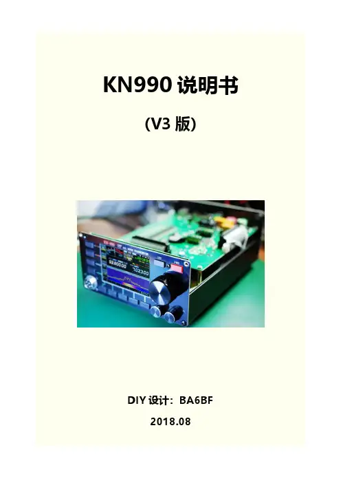
KN990说明书(V3版)DIY设计:BA6BF2018.08目录一、前后面板介绍 (1)二、开关机 (2)三、界面简介 (2)四、工作频率(VFO) (2)五、调制模式 (3)六、菜单 (3)6.1. 界面 (4)6.2. 表选择 (4)6.3. 调制模式 (4)6.4. 上下边带 (4)6.5. 旋钮功能 (4)6.6. VFO/存储模式 (5)6.7. 免提 (5)6.8. BK-IN (5)6.9. 高放 (5)6.10. 自动天调 (6)6.11. 增量 (6)6.12. 异频 (6)七、副屏 (6)八、CAT 计算机辅助控制系统 (10)九、USB (11)十、系统设置 (11)10.1. 发射设置 (11)10.2. 电报 (12)10.3. 调频 (13)10.4. 系统 (13)10.5. 红白机 (15)10.6. 语言 (16)10.7. 关于 (16)十一、固件升级 (16)十二、截图 (22)十三、VFO范围限制 (22)KN990简介:KN990是BA6BF于2018年6月开发推出的一款采用中频DSP技术的短波全段全模式收发信机,4吋彩色液晶屏、全中文菜单,并带实时频谱显示(频谱刷新率达到30帧/秒,已远优于很多商业电台)。
其基本技术指标和广受好评的KN850类似,并因为采用了数字中频技术得到了一些不太一样的操作体验。
又因自带游戏模拟器,能让HAM们在CQ之余娱乐一把经典老游戏,因此还被HAM们戏称为业余收发信机中最好的游戏机。
KN990主要参数:频率范围:接收: 0.1~30MHz发射: 业余短波波段工作模式:SSB/CW/AM/FM/DIGITAL接收灵敏度:0.2uV最小频率步进:10Hz工作电压:12~15V DC电流参数:接收0.4A发射4A @Max整机尺寸: 160X80X220(mm)[不包括突出物]发射功率:额定15瓦调制方式:全部模式均数字调制及解调杂散抑制度:≥45dBc载波抑制:≥45dBc选择性:全部模式带宽均连续可调(最小带宽调整步进为10Hz)KN990说明书(V3版)一、前后面板介绍注意:U盘只有插在USB2口时才能正常工作二、开关机1. 开机:接通电源,点击电源键即可2. 关机:按住电源键,保持1秒左右即可关机3. 注意:开机之后对电台所有设置的修改,只会在长按电源键关机时保存,如果直接切断电源,那么断电前的修改都不会保存(录音是实时保存的,是个例外)三、界面简介1. 界面左边4个按钮称为“菜单”,分别对应前面板4个实体“菜单键”2. 界面下半部分称为“副屏”3. 副屏下方显示5个“副屏按钮”,分别对应前面板5个实体“副屏按钮”四、工作频率(VFO)1. 修改VFO:转动主旋钮,VFO范围:0-150M2. 修改步进:点击电源键并转动主旋钮3. 修改步进时可以直接在VFOA和VFOB之间切换4. 默认状态下,VFOA既是接收频率也是发射频率,当启用“异频”时,VFOA是接收频率,VFOB是发射频率五、调制模式1. 一共有SSB,CW,AM,FM,WFM五种调制模式2. 切换调制模式:点击菜单“调制模式切换”3. 切换边带:点击菜单按钮“上下边带”4. 边带设置有3种类型:上边带:强制上边带下边带:强制下边带自动:VFO<10M时下边带,VFO>=10M时上边带六、菜单菜单一共3页,使用前面板的DIS键切换6.1. 界面循环切换副屏,副屏会下文详细说明6.2. 表选择接收表有两个:“信号强度”和“音量表”发射表也是两个:“发射功率”和“驻波比”只有在发射时才能切换发射表!6.3. 调制模式循环切换SSB,CW,AM,FM,WFM五种调制模式其中SSB和CW会在不同边带时显示USB,LSB,CW,CWR6.4. 上下边带循环切换“上边带”,“下边带”,“自动”6.5. 旋钮功能指定前面板“多功能旋钮”当前正在设置哪个参数不使用:多功能旋钮不设置任何参数发射功率:1~15W发射功率发报速度:CW模式时自动键的发报速度,4~60wpm带宽:接收带宽,不同调制模式有不同的带宽范围,甚至是带宽不可调偏移:接收偏移,不同调制模式有不同的偏移范围,甚至是偏移不可调增量:下文会详细介绍,增量范围-9.99kHz~+9.99kHzVOX灵敏:免提(VOX)功能的灵敏度,1%~100%FM灵敏:FM静噪灵敏度,1%~100%WFM灵敏:WFM静噪灵敏度,1%~100%6.6. VFO/存储模式循环切换VFO模式,存储模式VFO模式:有2套工作参数(VFOA,VFOB),包括频率,调制模式,接收带宽,接收偏移,这些参数随时可以修改,关机时都会自动保存存储模式:有99套工作参数(MEMO1~MEMO99),包括频率,调制模式,接收带宽,接收偏移,这些参数随时可以修改,但是仅在存储列表界面使用“保存”按钮才可以保存存储模式相当于“收藏夹”功能,帮助用户记录一些喜欢的频点和它的调制模式用户甚至可以给存储的频道设置名称6.7. 免提也叫VOX,开启后将会根据音频输入的声音大小来自动进入发射状态,VOX的灵敏度和发射延迟均可以调整(下文会介绍)6.8. BK-INCW发射延迟默认为关闭状态,开启后将会关闭CW的发射延迟6.9. 高放将接收信号放大100倍6.10. 自动天调需配合KT系列自动天调使用点击后将会以当前VFO,CW模式,3W发射功率开始发射并通知自动天调开始工作自动天调完成调整后自动关闭发射6.11. 增量增量分为接收增量和发射增量两种接收增量和传统电台的“RIT”功能类似发射增量和传统电台的“⊿TX”功能类似此功能主要在发现对面电台频率不准确时使用接收增量和发射增量不可同时开启接收增量开启时,实际接收频率=VFO+增量值,发射频率不变发射增量开启时,实际发射频率=VFO+增量值,接收频率不变增量值范围:-9.99kHz~+9.99kHz6.12. 异频也叫Split,开启后VFOA将作为接收频率,VFOB将作为发射频率异频功能可以使接收和发射工作在完全不同的频段上,而增量只有±9.99k的偏移范围七、副屏1. 切换副屏:点击菜单“界面”2. 每个副屏都有对应的5个副屏按钮,大多为当前副屏相关的操作上:VFO模式时切换波段,存储模式时切换存储频道下:和"上"键功能相同,切换方向相反显示方式:大瀑布/小瀑布切换中心红色竖线表示当前VFO位置相邻两根竖线间隔为10kHz竖线上方会显示该处频率(精确到10kHz),当该处频率>=100M时不显示信号高度会自动适应屏幕高度,以避免强信号溢出屏幕范围,或者弱信号难以观察,所以频谱显示的高度并不代表绝对信号强度,而是当前频谱范围内所有信号的相对信号强度上:VFO模式时切换波段,存储模式时切换存储频道下:和"上"键功能相同,切换方向相反相邻竖线间隔为1kHz设置带宽:进入编辑带宽模式,主旋钮调整带宽,再次点击退出编辑带宽模式偏移:进入编辑偏移模式,主旋钮调整偏移,再次点击退出编辑偏移模式恢复默认:将当前滤波器参数恢复到默认参数发射/接收:切换发射滤波器和接收滤波器形状:切换带通图形显示的形状,分为锐利和柔和两种带宽和偏移的步进均为10Hz所有调制模式的滤波器参数都是独立的,互不影响所有调制模式的发射和接收滤波器也是独立的,互不影响不同调制模式会有不同的带通图形带通图形中白色竖线表示VFO位置,黑色竖线表示带通中心带通图形下方的白色数字表示带通范围的左右边界频率,黄色数字表示带通中心频率特别注意:SSB模式中发射偏移默认为300Hz,设置太低的话发射时会有载波泄漏的情况上:VFO模式时切换波段,存储模式时切换存储频道下:和"上"键功能相同,切换方向相反解码功能目前仅支持CW解码,需要使用CW模式(边带无关)界面上方显示点画信息,下方显示解码字符解码正确率依赖稳定的信号强度,标准的发报手法上:切换存储频道下:和"上"键功能相同,切换方向相反保存:将当前工作频率,调制模式,接收带宽,接收偏移,存储到当前选中的频道中清空:将当前选中的频道清除设置名称:进入编辑频道名称模式,大旋钮修改字符,上下键移动光标,再次点击退出编辑频道名称模式菜单“VFO/存储模式”可以切换到存储模式,此时将使用当前频道信息做为工作参数(包括工作频率,调制模式,接收带宽,接收偏移)最多可以保存99个频道只有当副屏停留在存储列表时,才可以切换到空白的频道上,当副屏在频谱界面并且当前处于存储模式时,点击上下键只会在非空白的频道中循环切换未设置名称的频道会显示MEMO+n,否则显示设置的名称操作:在发射模式/播放模式/录音模式中循环切换T1:发射模式->发射T1录音内容进行循环发射(发射时本机喇叭不会播放录音内容);播放模式->本机喇叭循环播放T1录音内容,但是不会发射;录音模式->清空旧的录音并准备开始新的录音,手咪的PTT键被按住时才会录音,当PTT键松开时录音会暂停T2:和T1功能相同,但是操作的是T2录音间隔:发射模式和播放模式的循环间隔,在发射模式中,只有发射录音时机器才会处于发射状态,在间隔时间里,机器处于接收状态,会正常解调声音最多支持T1和T2两条录音,每条录音最多可以录约15.977秒界面会以图形方式显示录音预览,线条的高矮表示声音的大小上:向上移动光标下:向下移动光标确定:进入选择的项目或开始编辑值,绝大部分编辑都是使用大旋钮调整值,上下键移动光标(如果光标可以移动的话)返回:返回上一层所有设置选项的解释会在下文详细说明八、CAT 计算机辅助控制系统KN990的CAT协议与Yaesu FT817兼容也就是说支持FT817的CAT软件都可以用来操作KN990,例如“Ham Radio Deluxe”接口:机器背部的方口USB(USB-B型,打印机USB口)波特率:38400九、USBKN990目前支持U盘,键盘,游戏手柄,三种USB设备机器背部提供了两个可以同时工作的USB口,但是注意U盘只有插在USB2时才能正常工作,其他设备两个口都支持当插入的USB设备被正常识别后界面会显示图标当插入的USB设备没有正常识别时会显示如下图标目前USB驱动并不太稳定,可能会出现有时能识别有时不能识别的情况,如果反复插拔依然不识别的话可以重启一下机器,一般都能解决十、系统设置系统设置有多级菜单,每个选项的名称后面带有“>”符号的表示这里是进入下一级菜单的入口,例如:10.1. 发射设置发射功率:1~15W,步进1W练习模式(不发射):开启此选项后除了自动天调以外,其他任何情况都不会发射,此选项和电报设置中的练习模式是联动的(相当于同一个选项,在两个菜单都有显示)免提灵敏度:也称为VOX灵敏度,开启免提时生效,此选项控制多大的输入音量可以触发免提发射关闭发射延迟:此选项同时控制免提和电报在发射完毕后等待多久关闭发射,此选项和电报设置中的关闭发射延迟是联动的(相当于同一个选项,在两个菜单都有显示)高驻波保护模式:关断模式->当驻波大于等于阈值时关闭发射,同时关闭自动天调和免提;降功率模式->当驻波大于阈值时开始逐渐降低实际发射功率,当驻波-阈值大于1后,实际发射功率降低到3W并不再继续降低高驻波保护阈值:控制触发高驻波保护的阀门值10.2. 电报键模式:手键->单键发报,按下时发射侧音,放开停止;自动键->双键发报,点键按下连续发点,画键按下连续发画,自动产生标准点画间隔;KN990的自动键模式和FT817相同,属于压一键模式练习模式(不发射):开启此选项后除了自动天调以外,其他任何情况都不会发射,此选项和发射设置中的练习模式是联动的(相当于同一个选项,在两个菜单都有显示)发报速度:自动键的发报速度,4~60wpm,步进1wpm侧音音调:同时控制发射时的本地侧音音调,和接收时的侧音音调,300~1200Hz,步进50Hz侧音音量:控制发射时的本地侧音音量,0%~100%双键反转:对调自动键的点画按键选择:电子键->使用机器背面的电键插口发报;话筒键->使用话筒的加减键发报关闭发射延迟:此选项同时控制免提和电报在发射完毕后等待多久关闭发射,此选项和发射设置中的关闭发射延迟是联动的(相当于同一个选项,在两个菜单都有显示)10.3. 调频FM静噪灵敏度:1%~100%,控制FM模式时信号强度低于多少时开始静音WFM静噪灵敏度:1%~100%,控制WFM模式时信号强度低于多少时开始静音10.4. 系统时间日期:进入时间日期设置菜单,这个菜单很好理解就不做说明了,注意:设置的时间和时区是本地时间本地时区,UTC时间将根据设置的本地时区计算配置:导出到U盘:将本机所有的用户配置和出厂前的校准参数导出到U盘根目录“config.rtf”文件,请所有用户务必在收到机器后导出一次配置并且将配置文件妥善保留起来,让机器在出现一些不可预知的意外情况后可以自行恢复到出厂状态(这种情况几乎不可能出现,但是留个保险总是好的)从U盘导入:U盘根目录“config.rtf”文件并将其中的所有配置应用到本机,请不要导入其他机器的配置,因为配置里包含的出厂前的校准参数,每台机器都是不一样的恢复出厂:恢复所有用户配置到出厂状态,出厂前的校准参数不会恢复注意:仅支持FAT或FAT32格式的U盘,如果您的U盘不是这个格式(比如NTFS),使用Windows将U盘格式化到FAT32格式即可U盘只有在插入机器背面的USB2口才能正常使用,如果插在USB1口,可以识别为U盘,但是不能读写文件频率校准:如果您认为本机的工作频率不准确,可以在这里进行校准,校准范围±10kHz,上下键控制步进,大旋钮调整值机器名:修改主界面正上方显示的机器名,此名称同样会显示在开机画面中开机画面:炫酷的黑客帝国字符雨开机画面,可以选择完整/简洁/关闭3种方式关机画面:模拟老电视的关机效果,可以选择开启/关闭2种方式电源电压调整:如果您认为机器显示的电源电压并不准确,可以在这里用大旋钮输入您测量到的实际电压,然后按确定键即可升级:升级固件用,下文将详细说明10.5. 红白机超级玛丽:点击确定进入超级玛丽游戏魂斗罗:点击确定进入魂斗罗游戏键盘设置:设置USB键盘的游戏键位手柄设置:设置USB手柄的游戏键位目前仅支持两个内置的红白机游戏,未来会支持从U盘自由导入游戏目前只有键盘可以实现双人同时游戏,手柄仅支持单人KN990支持标准USB接口的HID协议手柄,如果您不确定应该选择哪一款,可以直接选购下面链接中的手柄:https:///item.htm?id=39333429326&spm=a1z09.2.0.0.59cb2e8 dqNTkGu&_u=735ehb1816b10.6. 语言语言:切换显示语言,支持简体中文和英语两种10.7. 关于版本号:本机固件的版本号硬件:BA6BF,硬件作者软件:Droid Zhang,软件作者说明书:显示本说明书的二维码,扫一扫就可以看到本说明了更新日志:显示更新日志的二维码,扫一扫就可以看到所有版本的更新内容了十一、固件升级准备工作:1. 准备一台可以上网的Windows系统的电脑2. 下载升级工具“KN990升级工具”网页下载/kn/kn990/KN990升级工具V2.exe QQ群共享下载:群号1243210523. 准备一条方口USB线(USB-B型,打印机USB线)4.准备一个U盘升级步骤:1. 电台进入设置->系统设置->配置->导出到U盘因为升级固件会强制恢复出厂一次,所以为了避免以前的设置丢失,必须手动导出配置2. 运行升级工具并等待自动获取到最新版本3. 使用方口USB线连接电台和电脑,并选择好串口号如果找不到电台的串口号,可以在Windows的设备管理器里检查一下是否是因为没有安装CH340驱动,驱动程序在群文件里有很多用户上传了,可以都试一下如果一切正常的话,升级工具界面上会显示绿色方形4. 电台进入设置->系统设置->升级此时升级工具界面就可以获取到电台的本机版本号了5 .点击升级工具的“开始升级”按钮,稍等片刻,升级工具和电台的进度条都开始走动6.升级完成后电台自动重启并强制恢复出厂,进入设置->系统设置->配置->从U盘导入,升级完成升级失败:如果因为断电,USB接触不良,电脑死机等意外情况导致升级过程中断,那么电台将无法正常开机(变砖),也无法按照上面的步骤重新开始升级,此时请按照如下步骤救机:1. 切断电台电源,强制关机2. 关闭升级工具重新打开3. 插上电台电源,使用方口USB线连接电台和电脑4. 按住电台前面板下方副屏按钮的右边最后一个键不放(下图,蓝圈所示),同时快速的点击一下电源键(注意是快速点击,不要按住,也不要按太久)此时电台会强制进入一个引导程序,并且界面显示如下:5. 升级工具选择串口号6. 如果串口号选择好之后读取到了电台固件版本且显示了绿色方形表示连接成功,然后点击开始升级即可,如果没有正常读取到电台固件,请回到步骤1重新开始7. 开始升级后耐心等待进度条走完即可注意:正常的升级过程无论发生什么意外都可以使用上面的步骤救机,永不变砖,所以请放行升级,不用担心十二、截图KN990提供界面截图功能1. 将U盘插入机器背面USB2口2.将USB键盘插入机器背面USB1口3. 按键盘PrtSc键(这个键一般在F12的右边)4. 截图需要几秒钟时间,期间电台界面会暂停刷新,截图完成后界面恢复刷新,并提示“完成”,截图文件保存在U盘根目录“kn990.bmp”注意:目前截到的图是上下颠倒的,可以使用Windows自带的画图工具全选(Ctrl+A)再垂直翻转一下即可使用,截图的颜色和电台的实际显示颜色会有色差十三、VFO范围限制KN990默认VFO范围为0~150M,为了一些特殊需求,提供了一个隐藏开关可以将VFO范围限制到3~30M1. 将VFO频率调整为12.345.672. 按住电源键关机3. 按电源键开机4. 此时VFO范围已变成3~30M如果想恢复到之前的VFO范围,再次执行以上步骤即可附录:KN990面板尺寸最新说明书固件更新日志。


AIWA CSD-ES50手提音响使用指南(快速上手)
特奥淘宝店
1、注意事项
◆请确认所用市电为正常范围
◆如用电池,忽略上步骤
◆如果本机从室外带至室内(冷处至温暖处),可能会造成部件结露现象,请稍等片刻◆机器顶部为CD舱,打开后,可见到激光头,此部件为敏感易损部件,勿触。
2、操作步骤
2.1 开机
将电源线从机器背部电池仓中取出,一端接机器(插口也在背部),一端接220V交流电插座
此时,手提音响处于待机/卡带播放,状态,如果要放卡带,按下相应按键,即可播放。
2.2 CD收听
如下图所示,轻按顶部CD舱盖右前部(有防滑触点),舱门即可弹起,将所要播放CD碟放入后,重新关上CD舱盖。
将下图所示FUNCTION波段,拨至CD档(即最右端),可以看到,液晶显示,CD碟开始读取,会显示出总曲目等相关信息,此时可以按PLAY等微触键进行操作
最左侧为耳机插孔,用来独享音乐。
2.3 收音机
FUNCTION波段,拨至RADIO档(即中间),右侧有BAND波段开关可以选择电台波段,MW为中波,SW为短波,FM为调频,选择相应波段,(SW,FM收听,需要将拉杆天线抽出),调节TURNING,选出相应电台欣赏。
2.4 磁带收听
将FUNCTION波段,拨至TAPE档,可对各仓卡带进行对应操作。
注:音响断开市电前,最好将波段拨至TAPE档(待机状态)。
2.5 音效及其他按键
FM STEREO 指示:当收听调频节目为立体声信号时,此灯亮起
下面黑色按键,可供用户选择各种音效,如增加低音,增加环绕效果。
感谢选择特奥淘宝店
祝:一切顺利
Ups专家。


L9901智能电力参数综合测试仪操作手册12L9901智能电力参数综合测试仪使用说明书要新占保定市力兴电子设备有限公司重要提示:1、仪器在不使用的情况下,请及时关闭电源!2、充电电池属于消耗部件,应注意维护,在使用时充电电池有效容量会随时间逐渐降低,从而使有效使用时间缩短,为了尽量提高电池寿命,请注意以下维护措施:●如果长期不使用仪器,请定期进行充电,电池应至少每月充电一次;●严禁亏电使用,亏电将严重缩短电池寿命,甚至使电池报废,当仪器欠电时,应马上关闭电源,进行充电。
避免因电池放电时间过长而导致电池失效。
3、指示灯说明:功能灯:输出过流时,功能灯亮红色并闪烁;电流输出过程中严重欠电时,功能灯亮蓝色。
充电灯:充电过程中亮红色;充电完成后亮绿色。
目录一、概述 (3)二、主要功能与特点 (3)三、主要技术指标 (4)四、面板及各键功能介绍 (4)五、变压器容量、空载、负载、零序阻抗测试及菜单操作方法 (5)六、注意事项 (21)七、售后服务 (21)八、附录 (22)一、概述:L9901智能电力参数综合测试仪,是专用于配电电力变压器容量测量、变压器空载及短路损耗测量的仪器。
该仪器电路设计精巧,思路独特,仪器内部采用先进的六路同步交流采样及数字信号处理技术,成功的解决了低功率因数测量及多路信号在市电条件下同步测量和计算的难题。
线电压采集引入角度,而非传统的乘固定系数,从而能够真实反映变压器试品的真实电压。
同时仪器测量引入了必要的校正(如: 电压校正、电流校正、温度校正、频率校正)。
从而使其性能优越,功能强大,体积小,重量轻,操作简单方便,数据准确可靠,可完全取代传统仪表的测试方法,可显示并记录用户关心的所有测量数据,可作为现场高精度交流指示仪表使用。
使用该仪器可大大提高工作效率,减轻劳动强度。
二、主要功能与特点:1. 容量的测量:仪器内置可充电电池,仪器本身可输出三相正弦波逆变电源,无需任何外部电源可实现配电变压器容量的测量和型号的判断,同时显示变压器阻抗电压和折算到额定温度、额定电流下的负载损耗。
2Zh参考下图在房间内设置音箱。
有关其他音箱系统的信息,请参见《使用说明书》。
1前置音箱(左)2前置音箱(右)3中置音箱4环绕声音箱(左)5环绕声音箱(右)6后置环绕声音箱(左)7后置环绕声音箱(右)9低音炮2放置音箱5.1 7.13连接音箱/低音炮Zh33将环绕声音箱 (4/5) 连接至4将低音炮 (9) 连接至 SUBWOOFER PRE 对于 7.1 声道系统(仅限于 RX-V575)4ZhZh54连接外部装置AV 1将外部装置连接至本机。
a 使用 HDMI 缆线将 BD/DVD 播放机连接至本机。
如果 BD/DVD 播放机当前通过 HDMI 缆线直接连接到电视,则应将此缆线从电视断开,然后将其连接到本机。
b 使用其他 HDMI 缆线将电视连接至本机。
c 使用数字光纤缆线将电视连接至本机。
在本机上播放电视视频时需要此连接。
如果电视支持 ARC (Audio Return Channel),则不需要此连接。
d 将电源线连接至交流墙壁电源插座。
•有关如何连接收音机天线或其他外部装置的信息,请参见《使用说明书》中的“准备工作”。
2打开本机、电视和 BD/DVD 播放机。
3使用电视遥控器将电视输入更改为来自本机的视频。
现在已经完成了连接。
请转到下一页,优化音箱设置。
•通过使用 HDMI 缆线将电视连接至本机,可使用电视上显示的菜单来配置本机的设置。
连接电源线之前(仅限通用型号)确保根据当地电压设置了 VOLTAGE SELECTOR 的开关位置。
电压为 AC 110-120/220-240 V ,50/60 Hz 。
6ZhYamaha Parametric room Acoustic Optimizer (YPAO) 功能将检测音箱连接,测量音箱与收听位置之间的距离,然后自动优化音箱设置(如音量平衡和音响参数)以适应您的房间。
5自动优化音箱设置 (YPAO)•测量过程中,测试音会以高音量输出。
请确保测试音不要吓到小孩。
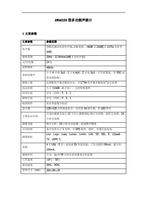
AWA6228型多功能声级计1 主要参数2 适用范围AWA6228 型多功能声级计是采用数字信号处理技术的新一代噪声测量仪器。
A、C、Z三种并行(同时)的频率计权及F、S、I 三种并行(同时)的时间计权可以同时测量多种评价指标;动态范围大于110dB;FLASH RAM 可靠保存测量结果,也可选配SD 卡存贮数据,仪器具有大容量存贮、录音、U 盘、读卡器等功能。
该仪器可广泛应用在环境保护、劳动卫生、工业企业、科研教学等领域,完成环境噪声测量、声功率级测量、机器设备噪声测量以及建筑声学测量。
3 使用方法3.1 按下“开/复位”键2秒钟以上后放开,仪器显示杭州爱华仪器有限公司图标,接着进入主菜单。
主菜单下游测量、设置、调阅、校准四个子菜单。
按下光标键可以使光标左右移动,按下确定键可以进入相应的子菜单。
按下删除键,系统参数恢复到缺省值。
3.2第一次使用仪器时应按测量要求设置测量时间、统计用频率计权等相关系统参数,系统参数设置好后,仪器会自动记录下来,下次再用时自动调入。
按下仪器的电源开/复位键,移动光标到“设置”菜单上,按确定键进入参数设置。
在测量界面下按下设置键也可直接进入参数设置。
注意:启动测量时不能进入参数设置。
3.2.1日历时钟调整进入参数设置后,将光标移到调整日历时钟处按确定键,就进入日历时钟调整界面。
3.2.2测量时间设置进入参数设置界面下,可以将光标移到测量时间的h,m,s 上。
用参数键可以任意设置测量时间,也可按确定键分档选取测量时间。
Ts=00h00m00s 表示测量时间无限制(手动)直到积分结果大到超出范围为止。
分档的测量时间有: 00h00m00s 、00h00m10s 、00h01m00s 、00h05m00s、00h10m00s、00h20m00s、00h30m00s、01h00m00s、02h00m00s、04h00m00s、08h00m00s、16h00m00s、24h00m00s.测量时间应按测量标准的要求进行设定,下次开机使用上次设置的测量时间。
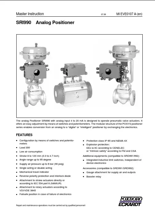
SRI990Analog PositionerThe analog Positioner SRI990with analog input4to20mA is designed to operate pneumatic valve actuators.It offers an easy adjustment by means of switches and potentiometers.The modular structure of the POSYS positioner series enables conversion from an analog to a“digital”or“intelligent”positioner by exchanging the electronics. FEATURES·Configuration by means of switches and potentio-meters·Load300·Low air consumption·Stroke8to120mm(0.3to4.7inch)·Angle range up to95degree·Supply air pressure up to6bar(90psig)·Single acting or double acting ·Mechanical travel indicator·Reverse polarity protection and interlock diode ·Attachment to stroke actuators directly or according to IEC534part6(NAMUR)·Attachment to rotary actuators according to VDI/VDE3845·Failsafe position in case of failure of electronics ·Protection class IP65and NEMA4X ·Explosion protection:EEx ia IIC according to CENELECor“Intrinsic safety”according to FM and CSA Additional equipments(compatible to SRD991/992):·Integrated inductive limit switches,independent of device electronicsAccessories(compatible to SRD991/SRD992):·Gauge attachment for supply air and outputs ·BoosterrelayMaster Instruction07.99MI EVE0107A-(en) Repair and maintenance operations must be carried out by qualified personnel!TABLE OF CONTENTSCHAP:CONTENT PAGE1METHOD OF OPERATION (3)1.1General (3)1.2Block diagram (3)1.3Operation (3)1.4Safety Requirements (4)2LABELS (5)3DESIGN (6)3.1Pneumatic accessories (7)4MOUNTING TO LINEAR ACTUATORS..8 4.1NAMUR Mounting(left hand) (8)4.2NAMUR Mounting(right hand) (10)4.3Direct Mounting (12)5MOUNTING TO ROTARY ACTUATORS.14 6PNEUMATIC CONNECTIONS (16)7ELECTRICAL CONNECTION (17)8START-UP (18)8.1General (18)Setting of-8.2-Direction of rotation of feedback shaft (19)8.3-Input Signal Range (20)Split Range (20)8.4-Gain(G) (21)8.5-Zero(ZERO)and Span(S) (21)8.6-Damping(D) (21)8.7-Travel indicator (21)8.8Air reducing throttles (22)8.9Basic adjustment of electronics (22)8.10Pneumatic test.....................22CHAP:CONTENT PAGE 9DECOMMISSIONING (22)10TROUBLE-SHOOTING GUIDE (23)11MAINTENANCE (24)11.1General (24)11.2Supply filter replacement (24)11.3Removal of the electronics unit (24)11.3.1Conversion of positioner (24)11.4Replacement of mechanical andpneumatic units (25)11.4.1Amplifier replacement (25)11.4.2Preamplifier replacement (25)11.4.3IP-module replacement (25)11.4.4Feedback unit replacement (25)12OPTION“Limit switch” (26)APPENDIX13SYSTEM CONFIGURATION (27)DIMENSIONS (28)2SRI990MI EVE0107A-(en)1METHOD OF OPERATION1.1GeneralThe intelligent positioner SRD9911and the pneumatic ac-tuator2form a control loop with the setpoint value w(from master controller or control system),the output pressure y and the position x of the actuator on valve3.The positioner can be attached to both linear actuators and rotary actuators.Actuators with spring force are controlled by a single acting positioner.Actuators without spring force are controlled by a double acting positioner.The positioner can be operated by means of switches and potentiometers.1.2Block diagram1.3OperationThe supply of the electronics unit is diverted from the cur-rent signal4to20mA at the input.The current value is measured and is suited in input circuit 9to the desired input range(control action or split range) via switches S4-S7.In circuit10the signal is provided with an adjustable time constant settable via potentiometer P5.The resulting internal signal is guided to the analog control circuit11,the gain of which is adjustable via potentiometer P4.The output of the control circuit drives the electro-mechanic converter(IP module)12,which controls the analog single acting or double acting pneumatic amplifier 14through the preampifier13.The output of the amplifier 14is the output pressure y(y1,y2)to the actuator.The pneumatic amplifiers are supplied with supply air Ps 1.4to 6bar(20to90psig).For the supply air,we recommend the FOXBORO ECKARDT FRS923filter regulator.The position x of the actuator is measured by the position sensor(conductive plastic potentiometer)15.The desired direction of rotation is set in17via switches S1and S2. The SPAN is suited to the stroke/rotation angle range via potentiometer P2,while ZERO is set in19via potentio-meter P3.With switch S3potentiometer P1provides an internal zero adjustment in18carried out by the manufac-turer(service function).The resulting feedback signal is guided to control circuit11.The IP module receives its maximum drive current via switch S8enabling checking of the funktion of the pneuma-tic unit.The position x of the actuator is independently displayed at the mechanical travel indicator16.The mechanical limit switch22(optional)enables indepen-dent alarm signals.MI EVE0107A-(en)SRI99031.4Safety requirementsAccident preventionThis device complies with regulations for the prevention of accidents Power-Driven Work Aids(VGB5)of1st October1985.In option“limit switch”do not touch control vane during operation-danger of injuries!Electrical safetyThis instrument satisfies the conditions for safety class III, overvoltage category I according to EN61010-1orIEC1010-1.Any work on electrical parts must be done by qualified per-sonnel if any supply is connected to the instrument.The instrument must be used for its designated purpose and connected in accordance with its connection diagram (see pages17and27).Locally applicable installation regulations for electrical equipment must be observed,e.g.in the Federal Republic of Germany DIN VDE0100resp.DIN VDE0800.The instrument contains no built-in fuses.The instrument must be operated with safety extra low voltage SELV or SELV-E.Safety precautions taken in the instrument may be render-ed ineffectual if the instrument is not operated in accord-ance with the Master Instructions.Limitation of power supplies for fire protection must be ob-served due to EN61010-1,appendix F or IEC1010-1.Explosion protection(Only if ordered)Technical data for explosion protection see Product Specifi-cations Sheet PSS EVE0107A-(en).For installations located in explosive atmospheres,all rele-vant national regulations and installation conditions must be observed,e.g.in the Federal Republic of Germany ElexV and DIN VDE0165.Attention:When repairing explosion-protected equipment,observe the national regulations.Repairs involving parts must be manufacturer’s original parts.The following applies to the Federal Republic of Germany: Repairs involving parts required for explosion protection must either be carried out by the manufacturer or by autho-rized personnel and confirmed by certificate.EMC and CEFor notes regarding Electromagnetic compatibility EMC and CE labels see Product Specifications Sheet PSS EVE0107 A-(en).In order to ensure EMC protection,the electronic board has to be screwed to the housing.4SRI990MI EVE0107A-(en)2LABELSC Additional label for option “Limit switches”DImprinted references regarding to settingsSRI990[Device specification,Model Code ]SER.No [Serial number ]ECEP [Number for special engineered version ]Measurement point label (Example)Directly fixed or attachedoption “Limit switches”(Example)MI EVE0107A-(en)SRI9905Nameplate A (Example)Without Ex-protectionNameplate A (Example)Classified intr.safe by CENELEC Type of protection “EEx ia ”3DESIGN6SRI990MI EVE0107A-(en)1a Adapter1/2"-14NPT(see accessories)1b Cable gland PG13.52Plug,interchangeable by Pos.13Screw terminals11+12for input(w)I–to measure input current(see also item23)4Ground connection5Female thread1/4-18NPT for output I(y1)6Female thread1/4-18NPT for air supply(s)7Female thread1/4-18NPT for output II(y2)8Direct connection hole for output I(y1)9Feedback shaft10Connection manifold for mounting to linear actuators 11Connection base for mounting to rotary actuators 12Travel indicator17Air reducing throttle*for output I18Air reducing throttle*for output II19Shaft for limit switch connection20Cover with window to1221Air vent,dust and water protected22Nameplate23Connections for current measurement,2mm dia.(integrated in side of terminals)26Arrow points to flat of feedback shaft at angle0°27Ball valve for protection class NEMA4X*Service only3.1Pneumatic AccessoriesWhen mounting,check the proper seating of the O-rings and bolt on the accessories with the two M8bolts.Unused outputs are closed by means of plastic plugs.MI EVE0107A-(en)SRI99073x1/4-18 NPT3x1/4-18 NPTL x B x H =100 x 30 x 45 mmL x B x H =83 x 20 x 25 mmL x B x H =121 x 39 x 81 mmL x B x H =110,5 x 39 x 81 mm4MOUNTING TO LINEAR ACTUTAORS4.1NAMUR Mounting -left hand -Applicable to actuators with cast yoke or pillar yoke acc.to NAMUR (DIN IEC 534-6).Mounting the positioner with pneumatic connections on theleft side and electrical connections on the lower right side.Attachment of the positioner to the actuator is made to the left using the mounting bracket and feedback lever for a NAMUR mount.Use:attachment kit EBZG -H for a cast yoke,or attachment kit EBZG -K for a pillar yoke.·The side outputs I (orI and II,see page 6)are used.The rear output I is closed bymeans of a lock screw 522588013.Pneumatic connections:Do not use Teflon tape for seal-ant.The fine fibres could disturb the function of the e only Loctite ®#243for sealant 1).Screw-type glands for electrical connections are positioned on the lower or right side.Any unused threaded holes are closed by plugs.When putting on the housing cover note that the air vent should face-down (see photo above).4.1.1Preparation of the positionerRotate the shaft stub of shaft 9so that the flat on the shaft stub is perpendicular to the arrow 26on the housing (detail see page 13).Fasten the feedback lever A to the shaft by means of spring washer and nut M8.1)Apply only to male thread4.1.2Preparation of the actuatorScrew the and lock it A carrier screw on It consists of a stud S ,which is screwed into the coupling piece K (with 3mm Allen key)and locked with a lock nut M6.The threaded sleeve H is screwed onto it and locked with a lock nut M6.Make sure that the bolt is adjusted to the right length!Fasten the mounting bracket to the left side of the yoke.For a cast yoke use a screw M8x 30,for a pillar yoke use two U-bolts and two nuts.4.1.3Mounting of the positionerFasten the positioner to the mounting bracket using two spring washers and two screws M8x 80.Note,the carrier bolt B is in the slot of the feedback lever A and the compensating spring F touches the carrier bolt.Fig.:Feedback leverFor optimum utilization of the positioner operating range,it is recommended that the arrangement is adjusted accor-ding to the following procedure before fixing.At an actuator position in the middle of travel range,the feedback lever po-sition should be perpendicular to the actuator stem and the angle range should be between 10°...+10°and 30°...+30°.Procedure:Set the actuator to the middle of its travel range by supply-ing it with an independent pressure.Fasten the mounting bracket so that carrier bolt and the mark on mounting bracket are about the same distance from the valve body.Fasten the positioner to the mounting bracket so that a suitable angle range is selected.It is recommended that the pneumatic and electrical con-nections are made after adjusting the position.8SRI990MI EVE0107A-(en)MI EVE0107A-(en)SRI99094.2NAMUR Mounting -right hand -Right-hand mounting is done if for instance left-hand moun-ting is not possible for structural reasons.Applicable to actuators with cast yoke or pillar yoke acc.to NAMUR (DIN IEC 534-6).Mounting the positioner with pneumatic connections on theright side and electrical connections on the left side.Attachment of the positioner to the actuator is made to the right using the mounting bracket and feedback lever for a NAMUR e:attachment kit EBZG -H for a cast yoke,or attachment kit EBZG -K for a pillar yoke.·The side outputs I (or I and II,see page6)are used.The rear output I is closed by means of a lock screw 522588013.Pneumatic connections:Do not use Teflon tape for seal-ant.The fine fibres coulddisturb the function of the e only Loctite ®#243for sealant 1).Screw-type glands for electrical connections are positioned on the left side.Any unused threaded holes are closed by plugs.When putting on the housing cover note that the air vent should face-down (see photo above).4.2.1Preparation of the positionerRotate the shaft stub of shaft 9so that the flat on the shaft stub is perpendicular to the arrow 26on the housing (detail see page 13).Fasten the feedback lever A to the shaft by means of spring washer and nut M8.1)Apply only to male thread4.2.2Preparation of the actuatorScrew the and lock it coupling It consists of a stud S ,which is screwed into the coupling piece K (with 3mm Allen key)and locked with a lock nut M6.The threaded sleeve H is screwed onto it and locked with a lock nut M6.Make sure that the bolt is adjusted to the right length!Fasten the mounting bracket to the left side of the yoke.For a cast yoke use a screw M8x 30,for a pillar yoke use two U-bolts and two nuts.4.1.3Mounting of the positionerFasten the positioner to the mounting bracket using two spring washers and two screws M8x 80.Note,the carrier bolt B is in the slot of the feedback lever A and the compensating spring F touches the carrier bolt.Fig.:Feedback leverFor optimum utilization of the positioner operating range,it is recommended that the arrangement is adjusted accor-ding to the following procedure before fixing.At an actuator position in the middle of travel range,the feedback lever position should be perpendicular to the actuator stem and the angle range should be between 10°...+10°and 30°...+30°.Procedure:Set the actuator to the middle of its travel range by supply-ing it with an independent pressure.Fasten the mounting bracket so that carrier bolt and the mark on mounting bracket are about the same distance from the valve body.Fasten the positioner to the mounting bracket so that a suitable angle range is selected.It is recommended that the pneumatic and electrical con-nections are made after adjusting the position.10SRI990MI EVE0107A-(en)A B4.3Direct MountingActuators with appropriately prepared yoke (PA200,PA350)enable mounting of the SRD991direcly to the actuator yoke.The attachment of the positioner is accomplished by bolting it directly to the actuator yoke using the feedback lever for a direct mount (with attachment kit EBZG -D).The rear output I and the side outputs I and II are used as follows (see page 6):·Actuator single acting,spring force closes:The rear output I is used (remove lock screw in hole D ).The side output I is closed by means of a lock screw 522588013.·Actuator single acting,spring force opens:The side output I is used.The rear output I is closed by means of a lock screw.·Actuator double acting:The rear output I and the side output II is used.The side output I is closed by means of a lock screw.Pneumatic connections:Do not use Teflon tape for sealant.The fine fibres could disturb the function of the e only Loctite ®#243for sealant 1).Screw-type glands for electrical connections are positioned on the side.Any idle female threads are closed by means of plugs.When putting on the housing cover note that the air vent should face-down (see photo above).1)Apply only to male thread.4.3.1Preparation of the positionerRotate the shaft stub of shaft 9so that the flat on the shaft stub is perpendicular to the arrow 26on the housing (detail see page 13).Fasten the feedback lever A to the shaft by means of spring washer and nut M8.4.3.2Preparation of the actuatorScrew in the carrier bolt B on the coupling piece K on the drive spindle S at the lower left and lock it by means of a nut M6.R4.3.3Mounting of the positionerFasten the positioner to the upper part of the yoke using 2spring washers and 2screws M8x 80,as shown above.The rear output I of positioner has contact to the air duct R in the yoke.Attention:Note the correct position of the O-ring on the yoke for the rear connection I!Note,the carrier bolt B is in the slot of the feedback lever A and the compensating spring F touches the carrier bolt.Fig.:Feedback leverA BFM6BKS4.3.4Mounting dimensions–direct mounting–5MOUNTING TO ROTARY ACTUATORS5.1Type of mountApplicable to rotary actuators that meet the VDI/VDE3845 standard for mounting.Installation position of positioner: Mount the positioner so that the pneumatic connections are in the same direction as the longitudinal drive axis of the actuator as shown in the photograph below.Attention:The feedback shaft9of the SRD has no me-chanical stop,therefore may spin round.The permissible rotation angle range is between+50and–50degrees around the arrow at the housing concerning the flat area of the feedback shaft(also see detail page13bottom).Since a rotary actuator has a rotary angle of about90degrees the mounting as described in the following must be carried out very precise.Attachment of the positioner to the actuator is made by using the rotary adaptor kit EBZG-R.·Either the side outputs I(or I and II)are used and the rear output I is closed by means of the lock screw522588013.Pneumatic connections:Do not use Teflon tape for seal-ant.The fine fibres could disturb the function of the SRD. Use only Loctite®#243for sealant1).Screw-type glands for electrical connections are used as needed.Any unused threaded holes are closed by plugs. Caution!Prevent accumulation of water in the instrument in this mounting position by sealing cable entry against water.Provide a continuous supply of dry instrument air.1)Apply only to male thread.2)Failsafe position:Defined position in case of failure of input signal 5.1.1Preparation of positionerValve must be in failsafe position2)and the direction of rota-tion of the actuator drive shaft must be known.These items are extremely important for proper functioning.These items can be checked as follows in case they are not clear: In the single-acting actuator the force of the installedsprings closes.The pressure-less actuator is in failsafe position.Through manually feeding compressed air itcan be seen whether the actuator drive shaft rotates to the left or to the right.In the powerless SRD is y1pressureless.In the double-acting actuator without spring reset both air chambers are basically equal.Failsafe position can be either“open”or“close”.Therefore,indication of the fail-safe position has to be determined by engineering.Then the direction of rotation may be determined bymanual feeding of compressed air.In the powerlessSRD is y1pressureless and y2under pressure.Bolt2is screwed into actuator drive shaft1for subsequent centering of the rotary adaptor3.The attachment console is mounted to the stroke actuator(see photo). Attachment diagram for bracket5.1.2Preparation of the actuatorFirst the rotary adaptor is being prepared:For attachment to a counter-clockwise or left turning ac-tuator secure the stud screw 4in the threaded hole “L ”of the rotary adaptor;hole “R ”remains open.See Fig.27.For attachment to a clockwise or right turning actuator secure the stud screw 4in the threaded hole “R ”of the rotary adaptor;hole “L ”remains open.See Fig.28.Now place the rotary adaptor 3with two washers 5on the feedback shaft 9of the positioner against the stop.Note :When the product temperature rises,the drive shaft 1be-comes longer.Therefore,the rotary adaptor 3must be mounted so that approx.1mm (0.04in.)of clearance re-sults between the drive shaft 1and the rotary adaptor 3.This is achieved by placing an appropriate number of washers 5on the feedback shaft stub 9before attaching the rotary adaptor.Two washers should result in a clearan-ce of 1mm.SRIFigure 27:Mounting if actuator is rotating to the leftNow screw and tighten the bolt in the coupling against the flat part of the feedback shaft(do not screw against thread!).Finally turn the feedback shaft in such a way that the arrow of the coupling points to the arrow of the SRI housing.Beginning and end positions of the actuator drive shaft 1and feedback shaft 9are marked in figure 27(left-rotating actuator)and in figure 28(right-rotating actuator)by arrows for the respective direction of rotation.The feedback shaft is now in the normal positioncorresponding to the failsafe position of the actuator.No shifting of feedback shaft anymore!5.1.3Mounting of positionerSRI and actuator are in failsafe position.Attach the SRI on the console in such a way that the catch of coupling 3is guided into the groove of shaft e bolt 2to center and align the positioner to the actuator.Be careful not to shift shafts 1and 9and that both shafts are exactly flush.Fasten the positioner to the bracket by means of 4lock wa-shers and 4screws M6x 12SRIFigure 28:Mounting if actuator is rotating to the rightFollowing alignment and mounting of the positioner to the valve,pneumatic tubing has to be provided.The connection illustrations depend on the respective ver-sion.Explanation of abbreviatons:sSupply airy1-d Output 1for direct mounting,depressurized atcurrentless electronics.When using this output y1has to be closed by means of hex.screw.y1Output 1,depressurized at currentless electronics.When using this output,y1-d has to be closed by means of sealing screw and O-ring.y2Output 2for double-acting actuator.Full pressure at currentless electronics.Closed at single-acting actuator.n1Hex.screw with NPT thread n2Sealing screw with O-ringsy1sy1s y2The safety requirements on page4must be observed! Unused cable glands should be closed off.Guide cable through gland1.The gland is suitable for cable diameters of6to12mm(0.24to0.47in).Observe the tightness of the cable entry.Provide electrical connection of input line at screw terminals 3marked11+and12.The terminals are suitable for wire cross-sections of0.3to2.5mm2(22-14AWG).Note:When connecting shielded cable connect the cable shield only to the system!Do not connect the cable shield to the SRI!40)Connection to terminals(pos.3+,3–):11+Input w+12–Input w–The input current can be measured at tip jacks23+and23-(integrated in terminals,underneath the screws).The tipjacks fit plugs with a diameter of2mm(0.08in)In order to improve EMV protection by integration into localgrounding the internal and external grounding conductconnection4is available.GW Binary output ext.supplied8START-UP 8.1GeneralFirst of all,the nameplate should be checked,especially with respect to references to Ex/non-Ex,input signal, single/double acting.Before starting the positioner the SRI has to be mounted to the actuator;an input signal4to20mA or split range have to be available.The supply air connection must have suf-ficient capacity and pressure of1.4to6bar(20to90psig) and should not exceed the maximum operating pressure of the actuator.The SRI990can be adjusted by means of switches and potentiometers when the housing cover is opened.At initial start-up various adjustments have to be set.The following procedure is recommended:·Setting of direction of rotation of feedback lever(chap-ter8.2)·Setting of input signal rangee.g.4to20mA or split range(chapter8.3)·Setting of gain(chapter8.4)·Setting of zero and span(chapter8.5)·Setting of damping(time constant,chapter8.6)·The position indicator12is attached to the desired posi-tion after selection of the transmission at indicator shaft (chapter8.7)·The air capacity throttles at the pneumatic output (screws17and18underneath of the SERVICE ope-nings)are factory-set to the operating value and are nor-mally not reset(exception see chapter8.8).·When attaching the housing cover make sure that the venting opening points to the bottom.1)Adjustment of electronic board(in workshop,see page23)Settings via switches and potentiometersFor the setting of the SRI990and the adjustment of various parameters8dip switches and5potentiometers are avail-able.See electronics imprint as follows:·Zero point(ZERO):P3·Span(S):P2·Gain(G):P4·Damping(D):P5·Electronics alignment:P11)Single-threaded potentiometers with limited rotation angle to set gain(G)and damping(D)are available,where the actual position is indicated by an arrow.To set zero point(ZERO),span(S)and the electronics alignment1)multiple-threaded potentiometers(approx.30rotations)without ro-tation limitation are used.The switches are for the setting of:·Direction of rotation of feedback lever(switches1,2)·Electronics adjustment(switch3)1)·Signal range(switches4,5,6and7)·Pneumatic test(switch8)The switchnumbers(1through8)are imprinted on the electronics.The possible switch position(“I”and“II”)are imprinted below switch8.The switch positions are defined as follows:“I”:“II”:8.2Setting of direction of rotationof feedback shaftIf the actuator moves from starting to end position,the di-rection of rotation of the feedback shaft is to the right or lefthand,depending on the mounting method of the positioner selected and on the configuration of the actuator(spring closes/opens/double-acting).For proper functioning this direction of rotation must be set at positioner(via switches1+2).The direction of rotation is defined as direction of rotation of the feedback shaft from the starting to the end position look-ing at the positioner from the front.See following illustration (shown is:left hand mounting,spring closes,direction ofDirection of rotation of feedback shaft of a single-actingDirection of rotation of feedback shaft of the double-actingactuator is a.o.determined by the mounting side and thetubing of the pneumatic outputs to the actuator.It has to beconsidered that in a powerless SRI990the output y1willbecome pressureless and y2contains air supply pressure.The direction of rotation of the feedback shaft is set viaswitches1+2;see the following illustration.L:left-hand rotating feedback shaft switch1+2on“I”R:right-hand rotating feedback shaftt:switch1+2on“II”Remarks:If the direction of rotation is not in the right man-ner,the actuator moves to the end position with full force,and the positioner cannot be controlled.DefinitionsStroke,stroke range of the membrane actuator is defined for rotary actuator as angle,angle rang e..0%position is the mechanical impact at actually closed valve(caution if using handwheel and mechanically adjustable stroke limitation!)100%position is the mechanical impact at actually open valve.8.3Setting of Input Signal RangeThe following input signal ranges can be set for the SRI990The switch positions for the setting of various signal ranges are imprinted on the electronics.See illustration.For 4to 20mA the switches 4to 7are set to position “I ”(as shown).This concludes the setting of the input signal range!Split RangeIf several positioners are operated at one current loop in se-quence with the standard signal 4to 20mA,individual valve positions may be allocated to each device,which also may overlap if necessary.This function is useful if an additional control range is de-manded which cannot be covered by one valve only.A valve of smaller nominal size can be applied overtaking the smallest quantities;a parallel mounted valve of bigger no-minal size takes on the larger quantities.Example:Setting the signal range to 12to 20mAIt is recommended to shut off current of the positioner prior to resetting of the input signal range (turn-off input signal).The switches 4and 5are set to position “I ”and switches 6and 7to position “II ”.The individual switch positions are shown in the following illustration.Split range,subdivision of input signal rangeExample:At low current,only the smaller valve positions;from approx.50%the large valve is added420mAm A12mA。
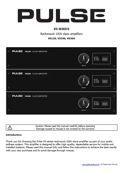
| VS Series User ManualVS SERIESRackmount 100V slave amplifiersVS120, VS240, VS360Caution: Please read this manual carefully before operatingDamage caused by misuse is not covered by the warrantyIntroductionThank you for choosing the Pulse VS-series rackmount 100V slave amplifier as part of your public address system. This amplifier is designed to offer high quality, dependable service for mobile and installed systems. Please read this manual fully and follow the instructions to achieve the best results with your new purchase and to avoid damage through misuse.To prevent the risk of fire or electric shock, do not expose any components to rain or moisture.If liquids are spilled on the casing, stop using immediately, allow unit to dry out and have checked by qualified personnel before further use. Avoid impact, extreme pressure or heavy vibration to the case No user serviceable parts inside – Do not open the case – refer all servicing to qualified service personnel.Safety• Check for correct mains voltage and condition of IEC lead before connecting to power outlet • Use double insulated speaker wire with adequate current rating for 100V speaker connections • Do not use 8Ω and 100V terminals at the same time•Do not allow any foreign objects to enter the case or through the ventilation grillesPlacement• Keep out of direct sunlight and away from heat sources • Keep away from damp or dusty environments• For rack-mounting, ensure adequate support for the weight of the amplifier• Ensure adequate air-flow and do not cover cooling vents at the front and rear of the amplifier • Ensure adequate access to controls and connectionsCleaning• Use a soft cloth with a neutral detergent to clean the casing as required•Use a vacuum cleaner to clear ventilation grilles of any dust or debris build-ups • Do not use strong solvents for cleaning the unitFront panel1. MASTER volume control2. POWER, SIGNAL, PEAK LED indicators3.Power switchConnection and setupConnect the rear IEC inlet (6) to the mains using the supplied mains lead (or an equivalent approved type). Ensure that the voltage is correct as indicated on the voltage selector (5) and that the mains outlet is switched on.Alternatively, the VS120 and VS240 can be powered by a 24V battery, such as a lorry or boat battery, by connecting the “+” and “-” of the battery to the 24Vdc INPUT (7) on the rear panel. Ensure that DC cables are capable of handling the current (10A min. recommended)The VS series amplifiers are intended to be fed from a mixer or mixer-amplifier signal output, providing additional power amplification for 100V speaker systems. The signal input should be connected to the SLAVE IN dual RCA connectors (12) on the rear panel. The VS series slave amplifiers are mono, so any stereo input signals will be summed together to provide a monaural output. Further slave amplifiers can be connected from the rear SLAVE OUT RCA sockets (11), allowing banks of amplifiers to operate together in large public address systems.Speaker outputsThe VS series slave amplifiers can be used either as 100V line amplifiers or standard low impedance power amplifiers. These 2 configurations cannot be used together, so it is important to decide which method will be used at the start.4. Ventilation grille - do not cover5. Mains voltage selector switch6. IEC mains inlet & fuse holder7. 24Vdc power connection (not VS360) 8. COM speaker terminal 9. 8Ω speaker terminal 10. 100V speaker terminal11. SLAVE OUT connectors (RCA) 12.SLAVE IN connectors (RCA)100V line systemsFor 100V line systems, connect the amplifier to the first speaker in the system using double-insulated speaker wire, which has adequate current rating to handle the total output of the amplifier.Connect the “100V” (10) output terminal to the positive (+) connection of the speaker and “COM” output (8) to the negative (-) connection of the speaker. Connect further speakers in parallel to the first speaker with all positive terminals and connected together and all negative terminals connected together as shown below.A 100V line speaker system can comprise of many speakers connected together. The determining factor for how many speakers can be used on a single amplifier is the power rating. For most purposes, it is advised to connect as many speakers as needed with a combined wattage of no more than 90% of the amplifier’s output power rating.The terminals of a 100V speaker are connected to a transformer and in some cases, this transformer may be “tapped” for different power ratings. These tappings can be used to adjust the wattage (and output volume) of each speaker in the system to help achieve the ideal total power of the system for the amplifier.Low impedance systemsThe VS series slave amplifiers can provide an output for a single 8Ω speaker by connecting the “8Ω” output (9) to the positive (+) speaker connection and “COM” output (8) to the negative (-) speaker connection. It is important to ensure that the speaker load is no less than 8Ω and that the power handling of the speaker is equal to or greater than the output power of the amplifier.OperationWhen all connections to the amplifier are made, turn the MASTER volume control (1) fully down and switch on the power (3) and the power LED will illuminate. Ensuring that the signal is active on the SLAVE IN inputs, turn up the MASTER gradually to the maximum required volume level.The output of the amplifier is represented on the SIGNAL LED and when the amplifier is running at its peak output, a PEAK LED will illuminate. Care should be taken that the Red PEAK LED is only lit momentarily during use. Anything longer than a short flash of this LED may be indicating distortion or clipping of the output signal and the MASTER volume should be turned down.SpecificationsVS120 VS240 VS360 Power supply 110/230Vac, 50/60Hz (IEC) DC power24Vdc screw terminals 24Vdc screw terminals N/AOutput power: RMS 120Wrms 240Wrms 360WrmsOutput: Line RCA slave out Input RCA slave in Controls Master volume THD<1.0%Dimensions 433 x 363 x 89mm 433 x 363 x 89mm 433 x 403 x 89mm Weight8.88kg 10.06kg11.60kgTroubleshootingEnsure IEC lead is in good condition and connected properlyIf 24Vdc power input is being used, check battery is chargedNo power LED on control panel Ensure POWER switch is on and check mains inlet fuseCheck input signals and condition of input connection leads Power LED is on but no other LEDs and no output Check MASTER volume control is turned upCheck speaker output terminals are connected correctly POWER and SIGNAL LEDs lighting but no output Check speakers are working (test on another amp if available)Check level of input signal is not too highOutput is very loud or distortedReduce MASTER volume levelCheck SLAVE IN signal level is not too lowIncrease MASTER volume level Check for quiet recording of media files on USBOutput is working but at very low level Check VOX override is not unintentionally suppressing audio playback Ensure cooling vents are clear from debris and dustCheck that 4Ω or 8Ω speakers are not connected to 100V terminalsEnsure total 100V speaker wattage is lower than amplifier ratingEnsure that 100V and 8Ω speakers are not both connectedAmplifier overheating Ensure that total load connected to 8Ω output is not less than 8ΩDisposal: The “Crossed Wheelie Bin” symbol on the product means that the product is classed as Electrical orElectronic equipment and should not be disposed with other household or commercial waste at the end of its useful life.The goods must be disposed of according to your local council guidelines.Errors and omissions excepted.Copyright© 2014. Pulse。
Cordless Vacuum | AR1201Important Safety InstructionsPlease do not use device near any form of heat sources.Please use accessories specified and provided by the manufacturer.Please refer all servicing to qualified personnel should there be any form of damage to the device. Keep this user manual for future reference/ troubleshooting.Please heed ALL safety cautions.1.2.3.4.5.SAFETY CAUTIONSUnboxingKeep device AWAY from fire and heat sources at all times.Do NOT attempt to disassemble or alter the device.Do NOT expose the device to excessive heat. (Direct sunlight e.g.).Do NOT immerse/ expose device to any form of fluids. Product label is located at the bottom of the product.Keep hair, loose clothing or any body parts away from any openings / moving parts.Turn off all controls before unplugging the device.Unplug from power outlet when not in use and before servicing.Do not use without dust bag and/or filter in place.Do not attempt to suck up anything that is burning. (Cigarettes, hot ashes etc. )1.2.3.4.5.6.7.8.9.10.Handle - motor assembly Main tube Floor brush/ NozzleAdapterDevice OverviewDevice Assembly* Please refrain from using any damaged components. Contact your local authorisedaiwa distributor/customer service. *Attach floor brush to main tube.Attach main tube to motor-handle assembly.Handle Power buttonSpeed variation switchTube release buttonMain tubeBattery compartment Dust cupDust cup release buttonDust cup filter Dust cupSuction - Floor brushDevice AssemblyORWall mount charger assemblyDust cup installationAttach floor brush to motor - handle assembly.Insert power cord into opening of the power cord holder as shown.Install power cord holder on the main mount.Install complete wall mount on wall.Click!Device Walkthrough - Power ON / OFFDevice Walkthrough - Suction mode variationDevice Walkthrough - Battery & Charging* LED lights will illuminate upon device being turned on. *Press to variate between 2 available suction modes(High speed / Quiet Mode).Press to start up.Connect charging cable to any power source and the AR1201 as shown.(Connect directly/ via wall mount)Charging time - Approx. 4 - 5 Hours Run time - Approx. 40 Minutes*Charging indicator light lights up red (0%-50% Charge)**Charging indicator light lights up orange (50%-90% Charge)**Charging indicator light lights up green (90%-100%% Charge)**Battery discharge - Low discharge (Green), High discharge (Orange)*Cleaning & maintenance - Waste RemovalCleaning & maintenance - Washing the dust cup & filterTroubleshootingRemove filter fromdust cup.Wash dust cup with a soft sponge/ brush and warm water.Wash filter withwarm water.Remove dust cup via dust cup release button.Release waste via waste releasemechanism as shown.*For optimal performance always empty dust cup container after each use.**Air dry dust cup filter before reinstallation.*The vacuum could not be turned on.Ensure device is charged.The vacuum is weaker.1. Ensure filter is cleaned and there is no obstructions present near the intake & throughout the vacuum suction pipe.2. Ensure device is charged.TroubleshootingCustomer serviceDevice specificationsThere is a leakage of waste.1. Ensure dust cup is empty.2. The dust cup might not be installed properly. Re-install dust cup filter.It is recommended to replace the dust cup filter every three (3) months (subjected to usage frequency) to ensure peak performance of the unit.For more product information please visit .Contact your local authorised dealer/ customer service. Refer to the warranty label provided in the box.Limited WarrantyPlease refer to the warranty label provided in the box.Note: Disassembling device voids warranty. Note: Liquid submersion voids warranty.Model - AR1201Rated total power consumption - 120W Rated current/ voltage - 500mA/ 26.5V Battery - Li-on 2200mAh Charging time - 4-5 Hours Pressure - ≥ 9.0kpa or 5.0kpaNoise level - 68 dB Size - 425*100*150mm Dust cup capacity - 300ml Weight ≈ net: 2.3kg, Gross: 3.7kg無線吸塵器使用說明書Instruction Manual在使用本產品之前,請務必先仔細閱讀說明書。
专业音响效果处理器YAMAHA SPX990 的使用与操作YAMAHA SPX990专业综合效果处理器是继YAMAHA 公司在SPX900、SPX100之后推出的,尽管推出至今已有四五年光景,同时也在众多的专业音响系统(包括一些剧场、夜总会、歌舞厅)中使用,该效果器共提供了280种效果程序,其中预置程序为1-80个,用户使用程序为1-99个,00是第100个程序,扩展记忆程序为-99,00是第100个程序,此处还包括了对混响和前期反射声的真实模拟,延迟和回声效果,调制效果,处理声效果,复合效果,门混响,音调效果,以及可循环的采样程序等。
SPX990在功能上比SPX900又上了一个档次,采用了20bitA/D和D/A转换器,增加了多种前后级效果,以及带有记忆的扩展卡槽,简捷的功能键,数据轮等,虽简化了操作步骤,但由于液晶显示屏所显示的数据有林林种种,又全都是英文缩写,使不少操作者感到使用起来极为不便,难以正确调整其中的各种参数,为此下面就具体介绍它的功能与操作,供使用者参考:一、控制与连接1、电源开关按此键可打开/关闭SPX990电源,当电源打开后,显示屏将调出上次关机时的程序和参数。
2、输入电平控制内/外部旋钮分别控制左/右声道的模拟信号输入电平。
3、输入电平表立体声输入电平表将左右声道分成八段,分别对应-42,-36,-30,-24,-18,-12,-6和削波灯指示。
4、记忆指示显示选择记忆的类型:预置,用户或记忆卡。
5、输入选择指示显示输入状态:立体声或单声道。
6、MIDI指示当接收到MIDI信号时,此显示器将被点亮。
7、程序号显示显示当前的程序号,在选择过程中程序号将闪亮,调出或存储后将常亮。
8、LCD液晶显示器液晶显示器将显示程序名,参数等信息。
9、功能键(上/下)用来直接调出或按照普通方法调出效果程序,还可用来存储操作,编辑液晶屏上选择的参数值。
10、数据调节轮用来调节程序号或参数值。