ABB综保REF615培训教材PPT幻灯片
- 格式:ppt
- 大小:5.54 MB
- 文档页数:35
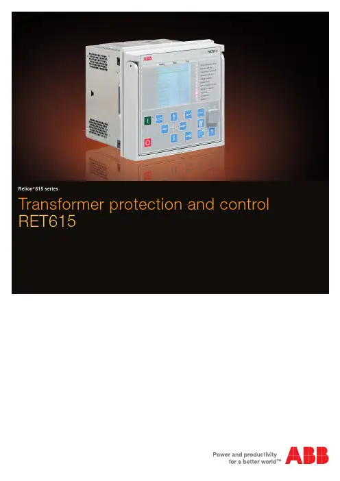
Transformer protection and control RET615Relion ®615 seriesCompact and versatile solution for utility and industrial power distribution systemsRET615 is a dedicated transformer protection and control IED for power transformers, unit and step-up transformers including power generator-transformer blocks in utility and industry power distribution systems.RET615 is a member of ABB’s Relion® protection and control product family and its 615 series. The 615series IEDs are characterized by their compactness and withdrawable-unit design. Re-engineered from the ground up, the 615 series has been designed to unleash the full potential of the IEC 61850 standard for communication and interoperability between substation automation devices.ApplicationRET615 is an advanced protection and control IED for two-winding power transformers and power generator-transformer blocks. RET615 is available in eight standard configurationsto match the most commonly employed power transformer vector groups and to coordinate the applied transformer neutral earthing principles with the relevant earth-fault protection schemes.Protection and controlRET615 features, three-phase, multi-slope stabilized (biased) stage transformer differential protection and an instantaneous stage to provide fast and selective phase-to-phase short-circuit, winding interturn fault and bushing flash-over protection. Besides second harmonic restraint an advanced waveform-based blocking algorithm ensures stability at transformer energization and a fifth harmonic restraint function ensures good protection stability at moderate overexcitation of a power transformer. Sensitive restricted earth-fault protection (REF) completes the overall differential protection providing detection of even single phase-to-earth faults close to the earthed neutral point of the transformer. Either the conventional high-impedance scheme or a numerical low-impedance scheme can be selected for protection of the transformer windings. When low-impedance REF protectionis used, neither stabilizing resistors nor varistors are needed. As a further benefit the transforming ratio of the neutral earthing CT may differ from that of the phase current transformers. Due to its unit protection character and absolute selectivity the REF protection does not need to be time graded with other protection schemes, and therefore high-speed fault clearance can be achieved.RET615 also incorporates a thermal overload protection function, which supervises the thermal stress of the transformer windings to prevent premature aging of the insulation of the windings. Multiple stages of short-circuit, phase-overcurrent, negative-phase-sequence and earth-fault back-up protection are provided for both the high voltage and the low voltage side of the transformer. Depending on the standard configuration the IED also includes three-phase overvoltage protection, three-phase undervoltage protection and earth fault protection based on a measured or calculated residual voltage. Furthermore, RET615 also offers circuit-breaker failure protection. Enhanced with an optional communication card, RET615 offers a fast three-channel arc-fault protection system for arc flash supervision of the circuit-breaker, busbar and cable compartment of metal-enclosed air-insulated switchgears.The optional RTD/mA module offered for the standard configurations A – D allow up to six temperature signals tobe measured via the RTD inputs and two transducer derived analog signals via the mA inputs. The RTD and mA inputs can be used for measuring the oil temperature at the bottom and top of the transformer. Furthermore, the RTD/mA inputs can be used for measuring the ambient air temperature. The RTD inputs also offer thermal protection of dry-type power transformers fitted with Pt-100 temperature sensors. Temperature measurement over the RTD /mA inputs extends the function of the three-phase thermal overload protectionof the IED. An RTD input can also be used as a direct resistance measuring input for position tracking of an on-load tap changer. Alternatively, tap changer position can be obtained via a mA-transducer. The analog temperature or tap changer position values can, if required, be sent using analog horizontal GOOSE messaging to other IEDs.RET615 also integrates functionality for the control of theHV-side circuit breaker via the front panel HMI or by meansof remote controls. RET615 also features two control blocks which are intended for motor-operated control of disconnectors or circuit-breaker trucks and their position indications. Further, RET615 offers a control block which is intended for motor-operated control of one earthing switch control and it’s position indication. The number of controllable primary devices depends on the number of available inputs and outputs in the selected configuration.The signal configuration of the IED can be adjusted using the signal matrix functionality (SMT) or the graphical application configuration functionality (ACT) of the Protection and Control IED Manager PCM600. The ACT supports creation of multi-layer logic by combining various logic functions blocks also including timers and flip-flops. By combining protection functions with logic functions the IED configuration can be modified to fit the special requirements of the application.2 Transformer protection and control | RET615RET615 | Transformer protection and control 3I 2>463I >51P-1 ARC50L3I >>>50P/51PIo > BF51NBFARC 50NL3I >>>50P/51PMAPMAP3I >51P-13I >>51P-2Io3I >>51P-23θ>T49TI 2>463I >BF51BF3I >T87TIo >51N-1Io1) Optional1)1)1)IoLo >87NLIo >>51N-2Protection function overview of the A configuration of RET615.Standardized communicationRET615 features genuine support for the new IEC 61850standard for communication in substationsand also for Parallel Redundancy Protocol (PRP) and High-availability Seamless Redundancy (HSR) protocols. The IED also supports DNP3, IEC 60870-5-103 and Modbus® protocols.For a redundant Ethernet solution the IED offers an optional fibre-optic communication module providing two optical and one galvanic Ethernet network interfaces. Alternatively, the IED features an optional galvanic communication module with two galvanic and one optical Ethernet network interfaces or three galvanic interfaces. The third Ethernet interface provides connectivity of any other Ethernet devices to an IEC 61850 station bus inside of a switchgear bay. The redundant Ether-net solution can be built on the Ethernet based IEC 61850, Modbus ® and DNP3 protocols.The implementation of the IEC 61850 substationcommunication standard in RET615 covers both vertical and horizontal communication, including GOOSE messaging with both binary and analog signals and parameter setting according to IEC 61850-8-1. The substation configuration language enables the use of engineering tools for efficient configuration and commissioning of substation devices. For accurate time stamping RET615 supports synchronization over Ethernet using SNTP or over a separate bus using IRIG-B.Preventive condition monitoringFor continuous control of its operational availabilityRET615 features a comprehensive set of monitoring functions to supervise the IED itself, the CB trip circuit and the circuit breaker. The IED monitors the wear and tear of the circuit breaker, the spring charging time of the CB operatingmechanism and the gas pressure of the breaker chambers. The IED also supervises the breaker travel time and the num-ber of CB operations to provide basic information for schedul-ing CB maintenance to support asset management.Single line diagramThe 615 series IEDs with large graphical display offer customizable visual single line mimic diagrams (SLD) with position indication for the relevant circuit breaker,disconnectors and the earthing switch. Apart from the default single line diagram, the IED may display related measured values, as provided by the chosen standard configuration. The SLD view can also be accessed through the web-browser based user interface. The default SLD can be modified according to user requirements using the graphical display editor of PCM600.Standard configurationsDescriptionThree-phase transformer differential protection for two-winding transformers, numerical restricted earth-fault protectionfor the high-voltage (HV) side, CB control (HV side) and optional RTD/mA inputsThree-phase transformer differential protection for two-winding transformers, numerical restricted earth-fault protectionfor the low-voltage (LV) side, CB control (HV side), optional RTD/mA inputsThree-phase transformer differential protection for two-winding transformers, high-impedance based restricted earth-fault protection for the high-voltage (HV) side, CB control (HV side) and optional RTD/mA inputsThree-phase transformer differential protection for two-winding transformers, high-impedance based restricted earth-fault protection for the low-voltage (LV) side, CB control (HV side) and optional RTD/mA inputsThree-phase transformer differential protection for two-winding transformers, numerical restricted earth-fault protectionfor the high-voltage (HV) side, phase-voltage based protection and measurement functions and CB control (HV side)Three-phase transformer differential protection for two-winding transformers, numerical restricted earth-fault protectionfor the low-voltage (LV) side, phase-voltage based protection and measurement functions and CB control (HV side)Three-phase transformer differential protection for two-winding transformers, high-impedance based restricted earth-fault protection for the high-voltage (HV) side, phase-voltage based protection and measurement functions and CB control (HV side) Three-phase transformer differential protection for two-winding transformers, high-impedance based restricted earth-fault protection for the low-voltage (LV) side, phase-voltage based protection and measurement functions and CB control (HV side)Standard configurationABCDEFGHStandard configurationsSupported functions, codes and symbolsFunctionalityProtectionStabilized and instantaneous differential protection for two-winding transformers Multi-purpose protection9)Master tripHV-side protectionNumerical stabilized low impedance restricted earth-fault protectionHigh impedance based restricted earth-fault protectionThree-phase non-directional overcurrent protection, low stageThree-phase non-directional overcurrent protection, high stageThree-phase non-directional overcurrent protection, instantaneous stageNon-directional earth-fault protection, low stageNon-directional earth-fault protection, high stageNegative-sequence overcurrent protectionResidual overvoltage protection5)Three-phase undervoltage protectionThree-phase overvoltage protectionThree-phase thermal overload protection for power transformers, two time constants Circuit-breaker failure protection2)LV-side protectionNumerical stabilized low impedance restricted earth-fault protectionHigh impedance based restricted earth-fault protectionThree-phase non-directional overcurrent protection, low stageThree-phase non-directional overcurrent protection, high stageThree-phase non-directional overcurrent protection, instantaneous stageNon-directional earth-fault protection, low stageNon-directional earth-fault protection, high stageNegative-sequence overcurrent protectionArc protection4)4 Transformer protection and control | RET615RET615 | Transformer protection and control 5H 1-2--111--122211-16)11113)13)1(3)A 1(6)21-11111)11)1---11--111--1(3)IEC-ANSI 87T MAP 94/86 87NL 87NH 51P-151P-2 50P/51P 51N-1 51N-24659G 275949T51BF/51NBF 87NL 87NH 51P-151P-2 50P/51P 51N-1 51N-2 4650L/50NLF 1-2--111--12221117)-11118)18)1(3)G 1-2-111112)12)122211--111--1(3)E 1-21-11111)11)122211--111--1(3)IEC 606173dI >T MAP Master Trip dIoLo >dIoHi >3I > 3I >> 3I >>> Io > Io >>I2> Uo > 3U < 3U > 3Ith >T 3I >/Io >BF dIoLo >dIoHi >3I > 3I >> 3I >>> Io > Io >> I2> ARCIEC 61850TR2PTDF MAPGAPC TRPPTRC LREFPNDF HREFPDIF PHLPTOC PHHPTOC PHIPTOC EFLPTOC EFHPTOC NSPTOC ROVPTOV PHPTUV PHPTOV T2PTTR CCBRBRF LREFPNDF HREFPDIF PHLPTOC PHHPTOC PHIPTOC EFLPTOC EFHPTOC NSPTOC ARCSARCD 1(6)2--111--1---11-16)11113)13)1(3)C 1(6)2-111112)12)1---11--111--1(3)B 1(6)2--111--1---1117)-11118)18)1(3)1, 2,... = number of included instances / I/Os( ) = optionalStandard configurationsSupported functions, codes and symbolsFunctionalityControlDisconnector controlEarthing switch controlDisconnector position indicationEarthing switch indicationTap changer position indicationCircuit-breaker control (HV-side)Condition MonitoringCircuit-breaker condition monitoringTrip circuit supervisionFuse failure supervisionRuntime counter for machines and devicesMeasurementDisturbance recorderRTD/mA measurementHV-side measurementThree-phase current measurementSequence current measurementResidual current measurementThree-phase voltage measurementResidual voltage measurementSequence voltage measurementThree-phase power, energy measurement, including power factorLV-side measurementThree-phase current measurementResidual current measurementInputs/OutputsAnalog inputsCTVTRTD inputs13)mA inputs13)Binary outputs/inputsBI13)BO13)6 Transformer protection and control | RET615RET615 | Transformer protection and control 7H 21321112111-11-1111117510)-.1210A 21321112-11(1)111----1-7-(6)11) (2)11)8 (14)12)10 (13)12)IEC-ANSI I ↔ O DCC I ↔ O ESC I ↔ O DC I ↔ O ES 84MI ↔ O CB CBCM TCM 60OPTM -X130 (RTD)3I I1, I2, I0In 3U Vn U1, U2, U0P , E 3I(B)In (B)F 21321112111-11-1111117510)--1210G 21321112111-11111111-7510)--1210E 21321112111-11111111-7510)--1210IEC 60617I ↔ O DCC I ↔ O ESC I ↔ O DC I ↔ O ES TPOSM I ↔ O CB CBCM TCS FUSEF OPTS -X130 (RTD)3I I1, I2, I0Io 3U Uo U1, U2, U0P , E 3I(B)Io (B)IEC 61850DCXSWI ESXSWI DCSXSWI ESSXSWI TPOSSLTC CBXCBR SSCBR TCSSCBR SEQRFUF MDSOPT RDRE XRGGIO130CMMXU CSMSQI RESCMMXU VMMXU RESVMMXU VSMSQI PEMMXU CMMXU RESCMMXUD 21321112-11(1)11-----117-(6)11) (2)11)8 (14)12)10 (13)12)C 21321112-11(1)111----1-7-(6)11) (2)11)8 (14)12)10 (13)12)B 21321112-11(1)11-----117-(6)11) (2)11)8 (14)12)10 (13)12)1, 2,... = number of included instances / I/Os( ) = optional1) Io selectable by parameter and the default value is Io measured 2)Io calculated is always used 3)IoB calculated is always used 4)IoB calculated and 3IB are always used 5)Uo selectable by parameter, Uo measured as default 6)IoB measured is always used 7)IoB measured and 3IB are always used 8)IoB selectable by parameter, IoB measured as default 9)Multi-purpose protection is used for, for example, RTD/mA based protection 10)One of the five inputs is reserved for future applications 11)With optional RTD/mA module 12)With optional binary I/O module ()13)The optional I/O module and the optional RTD/mA modules are mutually exlusiveNote that all directional protection functions can also be used in non-directional mode.The instances of a protection function represent the number of identical function blocks available in a standard configuration. By setting the application specific parameters of an instance, a protection function stage can be established.Contact us1M R S 756898 E , 4.0 F P 1 © C o p y r i g h t 2013 A B B . A l l r i g h t s r e s e r v e d .For more information see RET615 Product Guide or contact us:ABB Oy, Distribution Automation P .O. Box 699FI-65101 VAASA, Finland Phone: +358 10 22 11Fax: +358 10 22 41094ABB Limited, Distribution Automation Maneja, Vadodara – 390013, India Phone: +91 265 260 4386Fax: +91 265 263 8922/substationautomation。


ABB综保REF615培训教材一、ABB 综保 REF615 概述ABB 综保 REF615 是一款先进的综合保护继电器,广泛应用于电力系统中,为电力设备的安全稳定运行提供可靠的保护。
它具备强大的功能和灵活的配置,能够满足不同用户的需求。
REF615 采用了先进的数字技术和微处理器,具有高精度的测量、快速的故障判断和可靠的保护动作特性。
它可以对电力系统中的各种电气参数进行实时监测和分析,如电流、电压、功率、频率等,并根据预设的保护逻辑和定值,及时准确地判断故障类型和位置,迅速采取相应的保护措施,如跳闸、报警等,以避免故障的扩大和设备的损坏。
二、REF615 的主要功能1、过流保护REF615 能够监测线路中的电流,并在电流超过设定值时迅速动作。
过流保护可分为定时限过流保护和反时限过流保护两种方式。
定时限过流保护按照固定的时间延迟动作,适用于对动作时间要求较严格的场合;反时限过流保护则根据电流的大小自动调整动作时间,电流越大,动作时间越短,能够更好地保护设备免受过载的损害。
2、接地保护对于中性点不接地或经消弧线圈接地的系统,REF615 提供了零序电流保护和零序电压保护功能,能够及时检测到接地故障并采取相应的保护措施。
对于中性点直接接地的系统,REF615 则提供了零序过流保护和接地距离保护功能,确保接地故障得到快速可靠的处理。
3、过压保护和欠压保护REF615 可以实时监测系统电压,当电压超过过压设定值或低于欠压设定值时,及时发出跳闸指令,保护电力设备免受过高或过低电压的影响。
4、频率保护REF615 具备频率保护功能,能够监测系统频率的变化。
当频率超出正常范围时,如过高或过低,它会采取相应的保护动作,以保障电力系统的稳定运行。
5、重合闸功能在电力系统发生瞬时性故障时,REF615 支持重合闸功能,能够自动重合断路器,恢复供电,提高供电的可靠性。
6、测控功能除了保护功能外,REF615 还具备强大的测控功能。

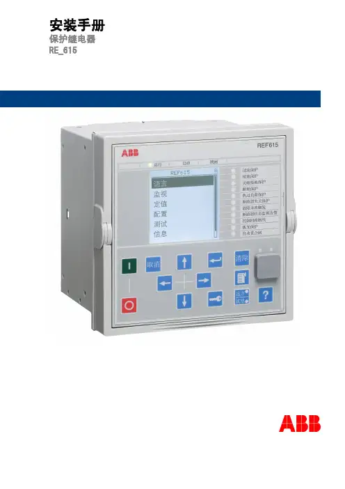
馈线保护测控装置REF615产品指南目 录1概述...............................................................12标准配置........................................................13保护功能........................................................34应用...............................................................75控制功能......................................................106测量.............................................................107故障录波......................................................108事件记录......................................................109故障数据记录...............................................1010断路器监视..................................................1011跳闸回路监视...............................................1112自检功能......................................................1113VT熔丝断线监视..........................................1114电流回路监视.. (1115)访问控制 (11)16输入和输出装置...........................................1217通信.............................................................1318技术数据......................................................1419显示选项......................................................3620安装方法......................................................3721外壳和插件单元...........................................3722选机及订货号...............................................3823配件及其订货号...........................................4224工具.............................................................4225ABB采用的解决方案....................................4426接线图..........................................................4527认证.............................................................4828参考资料 (4829)功能、代码和符号 (49)免责声明本文信息可能会更改,恕不另行通知。

Feeder Protection Relay REF615 Protection and ControlABB2Area of applicationREF615 is a dedicated feeder protection relay perfectly aligned for the protection, measurement and supervision of utility substations and industrial power systems. Re-engineered from the ground up, the new feeder protec-tion relay has been designed to unleash the full potential of the IEC 61850 standard for communication and inter-operability of substation automation devices.The relay provides main protection for overhead lines, cable feeders and busbar systems of distribution substa-tions. The feeder protection relay fi ts any radial distri-bution network regardless of earthing principle.Protection and controlThe feeder protection relay offers short-circuit, time overcurrent and thermal overload protection. The relay also features directional and non-directional earth-fault protection, sensitive earth-fault protection (SEF) and tran-sient-measuring earth-fault protection including detection of intermittent earth-faults in cable networks. Finally, the relay incorporates a fl exible multi-shot auto-reclose func-tion for clearing arc faults on open-wire overhead lines.Enhanced with an optional plug-in card, the relay offers a three-channel arc-fault protection system for supervision of the switchgear CB, cable and busbar compartment.REF615 also integrates basic control functionality, which facilitates the control of one circuit breaker via the relay’s HMI or a remote control system. To protect the relayfrom unauthorized access and to maintain the integrity of information, the relay incorporates a four-level, role-based user-authentication system with individual passwords for the viewer, operator, engineer and administrator level. The access control applies to the front panel HMI, the web browser based HMI and the PCM600 relay setting and confi guration tool.Standardized communicationREF615 supports the new IEC 61850 standard for inter-device communication in substations. The relay also sup-ports the industry standard Modbus ® protocol.The implementation of the IEC 61850 substation commu-nication standard in REF615 encompasses both verticaland horizontal communication, including relay-to-relaycommunication (GOOSE) and parameter setting services according to IEC 61850-8-1.Busbar protection à la GOOSEThe IEC 61850 implementation in REF615 also includes fast horizontal relay-to-relay communication over the station bus. Using GOOSE communication the REF615 relays of the incoming and outgoing feeders of a sub-station co-operate to form a stable, reliable and high-speed busbar protection system. The cost-effective GOOSE-based busbar protection is obtained just by confi guring the relays and the operational availability of the protection is assured by continuous supervision of the protection relays and their GOOSE messaging over the station bus. No separate hard-wiring is needed for the horizontal communication between the switchgearcubicles.IEC 61850 compliant Connectivity and Interoperability for Distribution SubstationsABB3Pre-emptive condition monitoringTo secure the operational availability of the protection, the REF615 relay incorporates a comprehensive range of monitoring functions to supervise the relay hardware and software, the relay communication, the CB trip circuit and the circuit breaker. Depending on the device con-fi guration chosen, the relay monitors the wear and tear of the circuit breaker, the spring charging time of the CB operating mechanism and the gas pressure of the breaker chambers. The relay also measures the breaker travel-time and counts the number of CB operations, thus collecting basic information for scheduling timely CB maintenance.Rapid set-up and commissioningDue to the ready-made adaptation of REF615 for theprotection of feeders, the relay can be rapidly set up and commissioned, once it has been given the application-specifi c relay settings. If the relay needs to be adapted to the special requirements of the intended application, the fl exibility of the relay allows the relay’s standard signal confi guration to be altered by means of the signal ma-trix tool (SMT) included in the PCM600 relay setting and confi guration tool.By means of Connectivity Packages containing detailed descriptions of ABB’s protection relays, with data signals, parameters and addresses, the relays can be automatically confi gured via the MicroSCADA Pro system, the COM600 Station Automation series devices or the PCM600 relay setting and confi guration tool.Unique plug-in design relayThe plug-in type relay design speeds up installation and testing of the protection. The factory-tested relay units can be withdrawn from the relay cases during factory and commissioning tests. The relay case provides automatic short-circuiting of the CT secondary circuits to prevent hazardous voltages from arising in the CT secondary cir-cuits when a relay plug-in unit is withdrawn from its case. The handle locking the relay unit into its case can be provided with a seal to prevent unintentional withdrawal of the relay unit.REF615 highlights⏹ Directional & non-directional earth-fault protection, sensitive earth-fault protection, and transient-measuring earth-fault protection also covering intermittent earth-faults on cable feeders ⏹ Device connectivity and systeminteroperability according to the IEC 61850 standard for next generation substation communication ⏹ High-speed busbar protection usinghorizontal GOOSE messaging over the station bus. No hard-wired copper cabling needed between switchgear cubicles. ⏹ Super-fast, three-channel arc-faultprotection for increased personal safety, reduced material damage and minimized system down-time ⏹ Enhanced disturbance recorderfunctionality including high sampling frequency, extended length of records, 12 analog and 64 binary channels and fl exible triggering ⏹ Plug-in type relay unit and a unique relay case design for a variety ofmounting methods and fast installation, routine testing and maintenance ⏹ One single tool for relay setting, signalconfi guration and disturbance record handlingABB OyDistribution Automation P . O. Box 699FI-65101 VAASA, Finland Phone: +358 10 22 11Fax: +358 10 41 094/substationautomationP r i n t e d i n F i n l a n d 5/2008 1M R S 756381C● = included, ❍ = optionalREF615 Technology SummaryTechnical details are available in the REF615 Product Guide 1MRS756379©C o p y r i g h t 2008 A B B . A l l r i g h t s r e s e r v e d . T h e i n f o r m a t i o n i n t h i s d o c u m e n t i s s u b j e c t t o c h a n g e w i t h o u t n o t i c e .Energizing inputsThree phase currents: 1/5 AOne residual current: 1/5 A or 0.2/1 A One residual voltage: 100/110/115/120 V Rated frequency: 50/60 Hz Binary inputs and outputsThree binary inputs with common groundOne additional binary input if no U 0 measurement Two NO double-pole outputs including TCS Two NO single-pole outputsOne change-over signal outputs One NO signal outputOne change-over IRF signal outputSeven binary inputs plus three binary outputs with one optional extension card and another six binary inputs and three binary outputs with a second optional exten-sion card, applies to standard configurations B and DCommunicationIEC 61850-8-1 with GOOSE messaging MODBUS TCP and RTU (optional)Time synchronization over Ethernet station bus using SNTP or over separate wiring using IRIG-B signal Auxiliary power supplyVariant 1: 48-250 V dc, 100-240 V ac; Variant 2: 24-60 V dcDimensions177 mm (4U) height, 177 mm (4U) width, 140 mm depth, weight 3.5 kg ToolsPCM600 ver. 2.0 SP1 for setting, signal configuration and disturbance record handling Web browser based user interface (IE 7.0 or later)COM600 Station Automation series products Ver. 3.2。
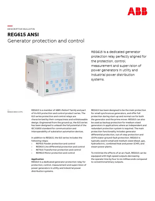
—DE SCR I P TI V E B U LLE TI NREG615 ANSIGenerator protection and controlREG615 is a dedicated generatorprotection relay perfectly aligned forthe protection, control,measurement and supervision ofpower generators in utility andindustrial power distributionsystems.REG615 is a member of ABB’s Relion® family and part of its 615 protection and control product series. The 615 series protection and control relays are characterized by their compactness and withdrawable design. Engineered from the ground up, the 615 series has been designed to unleash the full potential of the IEC 61850 standard for communication and interoperability of substation automation devices.In addition to REG615, the 615 series includes the following relays:• REF615 Feeder protection and control• RED615 Line differential protection and control • RET615 Transformer protection and control• REM615 Motor protection and control ApplicationREG615 is a dedicated generator protection relay for protection, control, measurement and supervision of power generators in utility and industrial power distribution systems. REG615 has been designed to be the main protection for small synchronous generators, and offer full protection during start-up and normal run for both the generator and the prime mover. REG615 can also be used as backup protection for medium-sized generators in applications where an independent and redundant protection system is required. The main protection functionality includes generator differential protection, out-of-step protection and 100% stator ground-fault protection. REG615 is typically used in small and medium-sized diesel, gas, hydroelectric, combined heat and power (CHP), and steam power plants.To minimize the effects of an arc fault, REG615 can be equipped with high-speed outputs decreasingthe operate time by four to six milliseconds compared to conventional binary outputs.—REG615 ANSI 5.0 FP1R EG615 A N S I D E S CR IP TI V E B U L L E TIN 2Human-machine interface (HMI)As a member of the Relion® product family, REG615 shares the same Human Machine Interface (HMI) look and feel as the other Relion protection and control relays. The same look and feel includes the location of a push button with a certain function and the menu structure.REG615 is equipped with a large graphical display which can show customizable single-line diagrams (SLD) with position indication for the circuit breaker, disconnectors and the grounding switch. Also measured values provided by the chosen standard configuration can be displayed. The SLDs are customized using PCM600 and can have multiple pages for easy access to selected information. The SLDs can be accessed not only locally but also via the web browser-based HMI.Standardized communication and redundancyREG615 fully supports the IEC 61850 standard for communication and interoperability of substation automation devices, including fast GOOSE messaging, IEC 61850-9-2 LE and Edition 2, offering substantial benefits in terms of extended interoperability. The generator and interconnection relay further supports both the parallel redundancy protocol (PRP) and the high-availability seamless redundancy (HSR) protocol, together with the DNP3, IEC 60870-5-103 and Modbus® protocols. REG615 is able to use two communication protocols simultaneously. For redundant Ethernet communication, REG615 offers either two optical or two galvanic Ethernet network interfaces. A third port with a galvanic Ethernet network interface provides connectivity of bus inside a switchgear bay. The redundant Ethernet solution can be built on the Ethernet-based IEC 61850, Modbus® and DNP3 protocols.The implementation of the IEC 61850 standard in REG615 covers both vertical and horizontal communication, including GOOSE messaging with both binary and analog signals as well as parameter setting according to IEC 61850-8-1. Also IEC 61850-9-2 LE process bus with sending sampled values of both analog voltages and currents, in addition to receiving sampled values of voltages, is supported. The sampled values can be used for synchro-check as well to ensure safe interconnection of two networks. For process bus applications, which require high-accuracy time synchronization, IEEE 1588 V2 is used, with a time stamp resolution of not more than four microseconds. IEEE 1588 V2 is supported in all variants with a redundant Ethernet communication module. In addition, REG615 supports synchronization over Ethernet using SNTP or over a separate bus using IRIG-B.01Main benefits • Withdrawable plug-in unit design for swift instal-lation and testing • Extensive range of protection functionality forboth synchronous generators and interconnec-tion points of distributed generation units • Ready-made standard configurations for fast andeasy setup with tailoring capabilities • Extensive generator protection with 100% statorground- fault, generator differential and out-of-step protection • Advanced interconnection protection fulfillingthe latest grid codes for higher grid stability and reliability • IEC 61850 Edition 2 and Edition 1 support, includ-ing HSR and PRP, GOOSE messaging and IEC61850-9-2 LE for less wiring and supervised com-munication • IEEE 1588 V2 for high-accuracy time synchroniza-tion and maximum benefit of substation-level • Ethernet communication • Large graphical display for showing customizableSLDs, accessible either locally or through a web browser-based HMI • Ring type terminals in the back1.Protection function overview of REG615standard configuration C2. Protection function overview of REG615standard configuration DLife cycle servicesABB offers full support for all protection and control relays throughout their entire lifecycle. Our extensive life cycle services include training, customer support, maintenance and modernization.02—Standard configurations—Supported functionsR EG615 A N S I D E S CR IP TI V E B U L L E TIN5—Supported functionsstandard configuration.() = optionTR = The function block is to be used on the terminal side in the application—1) "Io measured" is always used.2) "Io calculated" is always used.3) Master trip is included and connected to the corresponding HSO in the configuration only when the BIO0007 module is used. If additionally the ARC option is selected, ARCSARC is connected in the configuration to the corresponding master trip input.4) Power quality option includes current total demand distortion, voltage total harmonic distortion, voltage variation and voltage unbalance.5) Available only with IEC 61850-9-26) Available only with COM0031 (0037)1M A C 808933-D B R E V A J A N 2018—We reserve the right to make technicalchanges or modify the contents of this doc-ument without prior notice. With regard to purchase orders, the agreed particulars shall prevail. ABB Inc. does not accept anyr esponsibility whatsoever for potential er-rors or possible lack of information in this document.We reserve all rights in this document and in the subject matter and illustrations con-tained therein. Any reproduction, disclosure to third parties or utilization of its contents – in whole or in parts – is forbidden without prior written consent of ABB Inc.C opyright© 2017 ABB All rights reserved—ABB Inc.4300 Coral Ridge DriveCoral Springs, Florida 33065Phone:+1 954 752 6700/mediumvoltage/substationautomation。

馈线保护继电器REF615用户指南目 录1概述...................................42标准配置...............................43保护功能...............................54应用...................................75控制功能...............................96测量功能...............................97故障录波...............................98事件记录...............................99故障数据记录...........................910断路器监视.............................911跳闸回路监视..........................1012自检功能 (1013)访问控制 (10)14输入和输出............................1015通信..................................1116技术数据..............................1217显示选项..............................2818安装方法..............................2919继电器外壳和继电器插件单元............2920整机订货号............................3021配件订货号............................3322工具..................................3323端子图................................3524认证..................................3725参考资料 (3726)功能、代码和符号 (38)免责声明本文件中的信息可能会更改,恕不另行通知。
馈线保护测控装置REF615产品指南目 录1概述...............................................................12标准配置........................................................13保护功能........................................................34应用...............................................................75控制功能......................................................106测量.............................................................107故障录波......................................................108事件记录......................................................109故障数据记录...............................................1010断路器监视..................................................1011跳闸回路监视...............................................1112自检功能......................................................1113VT熔丝断线监视..........................................1114电流回路监视.. (1115)访问控制 (11)16输入和输出装置...........................................1217通信.............................................................1318技术数据......................................................1419显示选项......................................................3620安装方法......................................................3721外壳和插件单元...........................................3722选机及订货号...............................................3823配件及其订货号...........................................4224工具.............................................................4225ABB采用的解决方案....................................4426接线图..........................................................4527认证.............................................................4828参考资料 (4829)功能、代码和符号 (49)免责声明本文信息可能会更改,恕不另行通知。
ABB馈线保护测控装置REF615集保护、控制、测量、通信、监视和弧光保护功能于一体,完全根据国际标准IEC 61850平台研发和设计,从而使产品从根本上支持站内智能设备的互操作与水平通信等特性。
馈线保护测控装置REF615全新615系列配置灵活 应用广泛REF615可作为配电网中架空线和馈线的主保护,也可作为变压器等设备的后备保护。
主要用于电力变电站、电厂等电力行业以及水泥、冶金、石化、汽车、半导体、造纸、烟草等工业用户,也可用于市政、机场、港口、房地产等行业。
为满足用户需要,REF615可以提供7种标准配置的应用。
保护逻辑和相关功能均针对中国市场需求进行了特别优化。
保护控制功能齐全 集成弧光保护REF615提供带方向或无方向过流和接地故障保护,同时也支持过压、低电压、零序电压保护、热过负荷保护、灵敏接地保护及速断接地保护(包括间歇性接地保护)。
此外,该装置还集成了灵活配置的多轮次重合闸功能,可实现重合闸前、后加速和手合加速功能。
REF615加装可选配件,还可直接集成三个弧光保护通道。
用户无需另外购置和安装弧光保护装置即可实现对开关柜断路器、电缆和母线室的弧光检测和快速保护。
REF615支持当地和远方控制功能。
用户通过装置面板上的控制按钮或者后台监控系统(SCADA)即可实现对断路器的分、合闸操作。
为防止未授权用户误操作并保证用户按照相应权限操作,该装置定义了四个级别的操作权限:浏览者、操作员、工程师和管理员。
不同级别用户使用不同的账号和密码登陆。
这些权限设置适用于各种访问方式,包括装置面板操作,web访问及使用PCM600装置配置工具。
基于IEC 61850设计 支持水平通信REF615支持IEC 61850规约从而真正实现站内智能设备间的相互5-103。
REF615按照IEC 61850 规约设计,包括与后台监控系统的通信和保护装置之间的GOOSE水平通信并符合IEC 61850-8-1的各项规范。
Motor protection and control REM615Relion ®615 seriesCompact and versatile solution for industrial power distribution systemsREM615 is a dedicated motor protection and controlIED perfectly aligned for the protection, control, measurement and supervision of asynchronous motorsin manufacturing and process industry.REM615 is a member of ABB’s Relion® protection and control product family and its 615 series. The 615 series IEDs are characterized by their compactness and withdrawable-unit design. Re-engineered from the ground up, the new 615 series has been designed to unleash the full potential of the IEC 61850 standard for communication and interoperability between substation automation devices.ApplicationREM615 constitutes main protection for asynchronous motors and their drives in manufacturing and process industry. REM615 is available in three standard configura-tions. Typically, the motor IED is used with circuit-breaker or contactor controlled HV motors, and contactor controlled medium sized and large LV motors in a variety of drives, including both continuously and intermittently operated asynchronous motors with varying load.Protection and controlREM615 offers all the functionality needed to managemotor starts and normal operation also including protection and fault clearance in drive and network disturbance situations. The main features of the motor IED include thermal overload protection, motor start-up time supervision, locked rotor protection and protection against too frequent motor starts. The IED also incorporates non-directional earth-fault protection, negative phase sequence current unbalance protection and backup overcurrent protection. Furthermore, the IED offers motor running stall protection, loss-of-load supervision and phase-reversal protection.Standard configurations B and C additionally offer directional earth-fault protection, three phase undervoltage protection, negative phase sequence overvoltage and positive sequence undervoltage protection. In addition, the B and C configurations offer frequency protection including over-frequency, underfrequency and rate-of-change frequency protection modes.The motor IED has been thoroughly adapted for earth-fault protection. Using cable current transformer sensitive and reliable earth-fault protection can be achieved. Phase current transformers in Holmgreen (summation) connection can also be used the residual current measurement. In this case possible unwanted operations of the earth-fault protection due to CT saturation at motor start-up can be prevented using the IED’s internal interlocking features or a suitable stabilizing resistor in the neutral return path.The optional RTD/mA module offered for standard configurations A and B facilitates the measurement of up to eight analog signals via the six RTD inputs or the two transducer derived analog signals via the mA inputs. The RTD and mA inputs can be used for temperature measurement of motor bearings and windings, thus extending the functionality of the thermal overload protection and preventing premature aging of the motor winding. Furthermore, the RTD and mA inputs can be used for measuring the ambient air temperature. The RTD/mA module enables the use of the optional multipurpose protection functions, which can be applied for tripping and alarm purposes based on RTD and mA measuring data or analog values communicated via GOOSE messaging.Enhanced with optional hardware, the IED also features three light detection channels for arc fault protection of the circuit breaker, busbar and cable compartment of metal-enclosed indoor switchgear. Fast tripping increases personnel safety and limits switchgear damage, should an arc fault occur.A standard configuration can be adjusted using the signal matrix functionality (SMT) or the optional graphical application configuration functionality (ACT) of the Protection and Control IED Manager PCM600. The ACT supports creation of multi-layer logic by combining function blocks along with timers and flip-flops. By combining protection and logic functions the IED can be modified to fit the requirements of the application.REM615 also integrates functionality for the control of one switching device via the front panel HMI or by remote control.Standardized communicationREM615 features genuine support for the new IEC 61850 standard for inter-device substation communication. It also supports the DNP3, the IEC 60870-5-103 protocol and the industry standard Modbus® protocol. For increased communication availability and reliability the IED offers an optional second and third Ethernet network interface.2 Motor protection and control | REM615The self-healing Ethernet solution constitutes a cost efficient communication loop controlled by a managed switch.The managed switch controls the consistency of the loop, routes the data and corrects the flow of data in communication disturbance situations. The self-healing Ethernet ring canbe built on the Ethernet based IEC 61850, Modbus® and DNP3 protocols.The implementation of the IEC 61850 standard in REM615 covers both vertical and horizontal communication, including GOOSE messaging with binary and analog signals and parameter setting according to IEC 61850-8-1. For accurate time stamping REM615 supports synchronization over Ethernet using SNTP or over a separate bus using IRIG-B.3θ>M49M49, 66, 48, 51LRI s t, n<2 3I>BF51BF I2> M46M 3I<37Io>>51N-1 ARC50L Io>67N-1 ARC50NL U1<47U+ 3U<27 U2>47O-I3I>>>50I2>>46R I st>51LRESTART ESTARTLockoutrelay86MAP MAP1)f>/f<df/dt81 FUSEF60 MCS3I MCS3IIo> B F51NBF51P-13I>1) Optionalo1)1)Protection function overview of the B configuration of REM615.Pre-emptive condition monitoringFor continuous control of its operational availability REM615features a comprehensive set of monitoring functions includingsupervise the IED itself, the CB trip circuit, the current circuit,fuses, circuit breaker and motor runtime counting.Single line diagramThe 615 series IEDs with large graphical display offercustomizable single line mimic diagrams (SLD) with positionindication for the switching devices. The IED can alsodisplay measured values provided by the chosen standardconfiguration. The SLD is also available via the web-browserbased HMI. The default SLD can be modified according touser needs using the graphical display editor of PCM600.REM615 | Motor protection and control 3Supported functions, codes and symbolsFunctionalityProtectionThree-phase non-directional overcurrent protection,low stage, instance 1Three-phase non-directional overcurrent protection, instantaneous stage, instance 1Non-directional earth-fault protection, low stage, instance 1 Non-directional earth-fault protection, high stage, instance 1 Directional earth-fault protection, low stage, instance 1Three-phase undervoltage protection, instance 1Positive-sequence undervoltage protection, instance 1 Negative-sequence overvoltage protection, instance 1 Frequency protection, instance 1Frequency protection, instance 2Negative-sequence overcurrent protection for motors, instance 1 Negative-sequence overcurrent protection for motors, instance 2 Loss of load supervisionMotor load jam protectionMotor start-up supervisionPhase reversal protectionThermal overload protection for motorsCircuit breaker failure protectionMaster trip, instance 1Master trip, instance 2Arc protection, instance 1Arc protection, instance 2Arc protection, instance 3Multi-purpose protection, instance 1 1)Multi-purpose protection, instance 2 1)Multi-purpose protection, instance 3 1)A•••2)•2)------••••••••••ooooooIEC-ANSI51P-1 (1)50P/51P (1)51N-1 (1)51N-2 (1)67N-1 (1)27 (1)47U+ (1)47O- (1)81 (1)81 (2)46M (1)46M (2)3751LR49,66,48,51LR46R49M51BF/51NBF94/86 (1)94/86 (2)50L/50NL (1)50L/50NL (2)50L/50NL (3)MAP (1)MAP (2)MAP (3)C••-•3)•2)4)•••••••••••••••ooo---IEC 606173I> (1)3I>>> (1)Io> (1)Io>> (1)Io> → (1)3U< (1)U1< (1)U2> (1)f>/f<, df/dt (1)f>/f<, df/dt (2)I2>M (1)I2>M (2)3I<Ist>Is2t n<I2>>3Ith>M3I>/Io>BFMaster Trip (1)Master Trip (2)ARC (1)ARC (2)ARC (3)MAP (1)MAP (2)MAP (3)IEC 61850PHLPTOC1PHIPTOC1EFLPTOC1EFHPTOC1DEFLPDEF1PHPTUV1PSPTUV1NSPTOV1FRPFRQ1FRPFRQ2MNSPTOC1MNSPTOC2LOFLPTUC1JAMPTOC1STTPMSU1PREVPTOC1MPTTR1CCBRBRF1TRPPTRC1TRPPTRC2ARCSARC1ARCSARC2ARCSARC3MAPGAPC1MAPGAPC2MAPGAPC3Standard configurationsDescriptionMotor protection, optional RTD/mA inputsMotor protection with current, voltage and frequency based protection and measurement functions, optional RTD/mA inputs Motor protection with current, voltage and frequency based protection and measurement functionsStandard configurationABC• = included o= optionalB••-•3)•2)5)•••••••••••••••ooooooStandard configurations4 Motor protection and control | REM615Supported functions, codes and symbolsFunctionalityControlCircuit-breaker controlDisconnector position indication, instance 1Disconnector position indication, instance 2Disconnector position indication, instance 3Earthing switch indicationEmergency start-upCondition MonitoringCircuit-breaker condition monitoringTrip circuit supervision, instance 1Trip circuit supervision, instance 2Current circuit supervisionFuse failure supervisionRuntime counter for machines and devicesMeasurementDisturbance recorderThree-phase current measurement, instance 1Sequence current measurementResidual current measurement, instance 1Three-phase voltage measurementResidual voltage measurementSequence voltage measurementThree-phase power and energy measurement, including power factor RTD/mA measurementFrequency measurement IEC 61850CBXCBR1DCSXSWI1DCSXSWI2DCSXSWI3ESSXSWI1ESMGAPC1SSCBR1TCSSCBR1TCSSCBR2CCRDIF1SEQRFUF1MDSOPT1RDRE1CMMXU1CSMSQI1RESCMMXU1VMMXU1RESVMMXU1VSMSQI1PEMMXU1XRGGIO130FMMXU1IEC-ANSII ↔ O CBI ↔ O DC (1)I ↔ O DC (2)I ↔ O DC (3)I ↔ O ESESTARTCBCMTCM (1)TCM (2)MCS 3I60OPTM-3II1, I2, I0In3UVnU1, U2, U0P, EX130 (RTD)fIEC 60617I ↔ O CBI ↔ O DC (1)I ↔ O DC (2)I ↔ O DC (3)I ↔ O ESESTARTCBCMTCS (1)TCS (2)MCS 3IFUSEFOPTS-3II1, I2, I0Io3UUoU1, U2, U0P, EX130 (RTD)fC••••••••••••••••••••-•B•••••••••••••••••-••o•A••••••••••-•••••----o-1) Multi-purpose protection is used for, for example, RTD/mA based protection2) Io selectable by parameter, Io measured as default3) Io selectable by parameter, Io calculated as default4) Uo selectable by parameter, Uo measured as default5) Uo calculated and negative sequence voltage selectable by parameter, Uo calculated as defaultNote that all directional protection functions can also be used in non-directional mode.The instances of a protection function represent the number of identical function blocks available in a standard configuration.By setting the application specific parameters of an instance, a protection function stage can be established.REM615 | Motor protection and control 5Contact us1M R S 756902 C , 3.0 © C o p y r i g h t 2010 A B B . A l l r i g h t s r e s e r v e d .For more information see REM615 Product Guide or contact us:ABB Oy, Distribution Automation P .O. Box 699FI-65101 VAASA, Finland Phone: +358 10 22 11Fax: +358 10 22 41094ABB Limited, Distribution Automation Maneja, Vadodara – 390013, India Phone: +91 265 260 4386Fax: +91 265 263 8922ABB Industrial ParkTorch Hi-tech Industrial Development Zone Xiamen, Fujian, 361006, P .R.China Phone: +86 592 570 2288Fax: +86 592 571 8598/substationautomation。