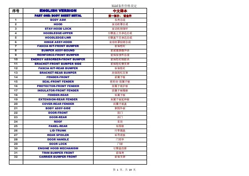
汽车英语维修手册翻译
- 格式:docx
- 大小:110.24 KB
- 文档页数:3
最全汽车常用中英文手册!这些故障保养零部件用语你必须知道!在汽车口笔译过程中,经常会遇到一些专业的知识和常用英语表达,比如汽车内饰外观、性能配置,数据法规等等,今天推荐一些故障保养零部件常用语给大家。
汽车常见的故障1. 油耗大有可能因为汽车故障问题,或发动机磨损老旧,或是胎压不足。
当然,一些不好的驾车习惯也会导致汽车吃油速度猛增。
如果你的车不是很旧,或你是一个非常优秀的司机,胎压又丝毫没有问题,你就可以去检查一下故障问题了...相关英文:Oil change with oil filter replacement 换机油和油滤Air filter replacement 发动机空气滤芯更换Tune the engine 发动机调整Fuel system cleaning 油路清理Fuel filter replacement 燃油滤清器更换2. 空调不凉、有异味不凉的原因制冷剂不足或过多,制冷剂与冷冻机油含杂质过多造成堵塞,或压缩机风扇问题。
有异味简单的讲就是冷凝器表面发霉了,有细菌...长时间下去会对车里人的健康有影响,请注意定时更换空调滤芯、清理空气道。
相关英文:Air conditioning repair/ adding Freon 空调修理或添加氟利昂Cabin filter replacement 换空调滤芯3. 行车过程中发动机温度超过正常标准原因:也许是冷却系统有严重的漏水情况,或是风扇传送带松脱,也可能是水泵轴与叶轮松脱,总之...送修吧...相关英文:Radiator repair 散热器修理Anti-freeze change 防冻液更换4. 刹车问题有时候刹车片薄了需要换,有时候刹车有尖锐的声音,等等刹车问题都需要认真对待哟。
相关英文:Break pads replacement 换刹车片Break fluid change 换刹车油Brake rotor resurfacing 刹车盘翻新Brake calipers adjustment 刹车卡钳调整Check level and refill brake fluid 检查添加刹车油5. 车打不着火如果你上车之后发现车子打不着火,那么很大的可能是你的电瓶坏掉了或是没电了...相关英文:Battery replacement 电瓶更换Alternator repair 交流发电机修理6. 轮胎异常磨损轮胎异常磨损虽然轮胎磨损是我们一定会面对的问题,但是不正常的轮胎磨损可能预示着你的爱车生病了。
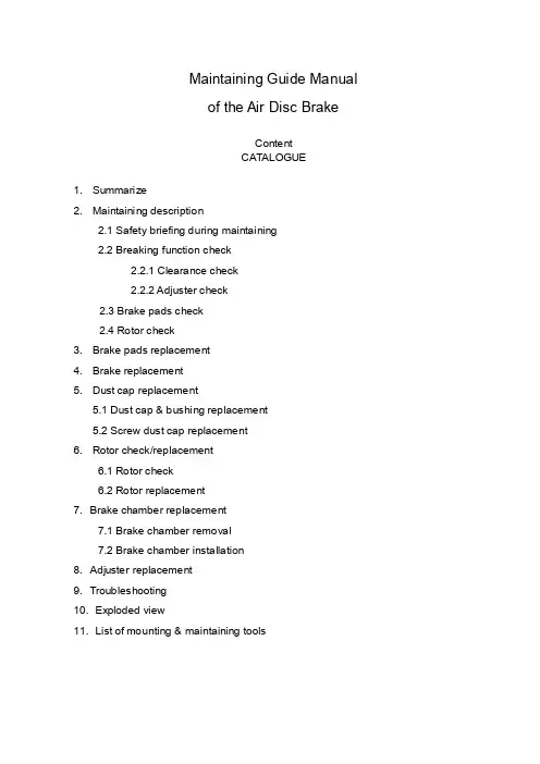
Maintaining Guide Manualof the Air Disc BrakeContentCATALOGUE1. Summarize2. Maintaining description2.1 Safety briefing during maintaining2.2 Breaking function check2.2.1 Clearance check2.2.2 Adjuster check2.3 Brake pads check2.4 Rotor check3. Brake pads replacement4. Brake replacement5. Dust cap replacement5.1 Dust cap & bushing replacement5.2 Screw dust cap replacement6. Rotor check/replacement6.1 Rotor check6.2 Rotor replacement7. Brake chamber replacement7.1 Brake chamber removal7.2 Brake chamber installation8. Adjuster replacement9. Troubleshooting10. Exploded view11. List of mounting & maintaining toolsBrief introduction of YOUFINYOUFIN was established on May 20th, 1998. It is a Sino-Foreign joint-venture enterprise registered in Wuhan Economic and T echnological Development Zone with multi-investors among which private investors dominate. It is a professional company engaged in manufacturing disc brakes and serving the principal automobile manufacturers by providing modularized supply. The main prod ucts cover hydraulic disc brakes and air disk brakes in close to thirty sizes.YOUFIN developed the air disc brake autonomously and patented the product. So far we are the only manufacturer in China that can mass produce air discs to be used in long distance coaches and inner city buses. It is evaluated that the quality of our products is close to the advanced international level in field use. The product development is part of the National T orch Plan and is also sponsored by the Small and Medium-sized Enterprise T echnical Innovation Foundation of Chinese Ministry of S&T.Our Air Disc Brake products are on an absolute leading position in China and the same international level as far as the key technology is concerned.1. SummarizeYOUFIN Air Disc Brake has four sizes (16’’, 17.5’’19.5’’, 22.5’’). It can satisfy different vehicles. The brakes have compact structure; automatically wear compensation and can easily changing the brake pad.2. Maintaining descriptionSafety briefing during maintainingIt’s most important to ensure safety driving and breaking by goodcharacteristics of the brake.Observe brake pad and rotor wear limits. When they warned already to assigned smallest thickness, it need replace immediately, otherwise, it may cause the accident. The pads scorches, grinds or greases must replace immediately.Every pad on each bridge must replace at the same time.When services the brake, the vehicle must park in smooth gound and the wheel withstand with the block/ stone prevent rolls.Note:●Must guarantee it does not occur with careless brake. When replace brakepad don’t make the brake, otherwise, it will hurts the body!●Do not use the compressed air or other cleaning up equipment clean thebrake, in order to avoid injures the body.●Be sure your hands and fingers place outside the caliper, in order to avoidinjures the body.●When moves and installs the brake should have some assistance, avoids ittoo heavy to hurts the body.●When take off the brake to make maintenance, it must fix on the clamp withhigh strength bolt, in order to avoid hurts the body.●Only allowed genuine YOUFIN kits and pads permitted by YOUFIN. Duringthe first 50 miles driving after new pad replacement, should avoid promptlybrake and brake at a long distance, Prevent overhigh temperature.●Allowed genuine YOUFIN kits and brake pads permitted by YOUFIN.●Only can use the recommendation kits in service. Screws the bolt/nutaccording to the request moment of force.Brake Function checkClearance checkProcess:●T ake off the hexagon bolt (39), loosen the pad retainer (38).●Remove pad retainer (38) from caliper.●Remove 3pcs of pad clip (37).●Move the cable (40) to the side.●Push the caliper towards the wheel and check the clearance with tune-upgauge.0.5mm ≤ clearance ≤ 1.2mmNote: Insert tune-up gauge between the caliper (1) and the brake pad (35). Should check the adjuster while the clearance is out of standard.Adjuster checkProcess:●Remove the rubber cap (12).●Turn hexagon head (22) clockwise by wrench to ensure clearance larger than3mm. (Or remove the brake pad and the push board)Note:a. Need enough room (3mm<clearance) for turn adjuster preventing un-fit.b. Never force to adjust the hexagon head (22) and/or the adjuster!Push the pressure arm 5 times in small increments and observe the hexagon head (22). While the adjuster is in good condition, hexagon head (22) must rotate clockwise.c. As the regulated quantity increase, rotation angle decreases.If the adjuster hexagon head (22):a) Not running at allb) Only running at first pushc) Running, but stopped in the middleWhile considers adjuster failed. Y ou should replace the brake on the basis of section 4 or change the adjuster in accordance with section 8.●Keep the clearances at 1mm (section 3) after adjuster check is finished.●Reinstall the rubber cap (12).Brake pads wearing check●Scorches, grinds and greased brake pad must replaces immediately.●Brake pads at the same bridge must replace at the same time.●Brake pad and pad clip must replace at the same time.Rotor checkProcess:●Remove the brake pad according to section 3.●T est thickness of the rotor.Note: Observe the brake pads and the rotor attrition situation. Excessive attrition of the rotor and the brake pads will reduce their potency and causes the brake fail!CAUTION: Rotors on the same bridge must replace at the same time. Single side rotor replacement is unacceptable. Recommend installs new brake pads whilereplace the new rotors.Rotor Dimension limitsRotor jumpiness (↗) check:2.4.1 Process:●Installs division indicator on the bracket (dial guage).●Measure jumpiness (↗) through turns the wheel. Jumpiness (↗) should lessthan 0.15.●Replaces the rotor to satisfy the request of section 6.●Modified brake pad should fulfil the specific requirements in section 3.2.4.2 Rotor test:At each change of Pads check the Rotor for grooves and cracks.The diagram at the right shows possible conditions of the surface.A = Small cracks spread over the surface are allowedB = Cracks less than 0.02in. (0.5mm) wide, running in a Radial direction, are allowedC = Grooves (circumferential) less than 0.06in. (1.5mm) wide are allowedD = Cracks in the vanes are not allowed and the Rotor MUST BE REPLACED.a = Pad contact area3. Brake Pad replacementNote: Do not use the pipe spanner/ board die! Keep your hands and fingers outside the caliper avoid the hurts of body!Brake Pad dismantle process:●T ake off hexagon bolt (39) from the Pad Retainer with spanner.●Remove the pad retainer from caliper (1).●T ake off the pad clip (37), which is above the pads (35,36) and push board (19).●Remove the sensor on brake pad.●T ake off the push board (19) & the brake pads (35,36).●Adjust hexagon head to make tappet back to the initial position.●Clean the pad groove & push board and anchor surface with brush.Note: Don’t hurt the dust cap (5 & 10). Be sure of no grease on installation surface!●Check the adjuster on the basis of section 2.2.2.Note: Fix the key while checking & turning the adjuster cap to avoid screw rotate.●Check the rotor according to section 2.4.3.2 Brake pad installing process:●Need enough room between the caliper & the rotor to insert brake pad.●Insert push board (19) at the place the caliper combine with the adjust screw.Note: Push board must on the bracket supporting surface. Adjust screw pin must in groove. Otherwise it will do harm to Adjuster mechanism. Ensure the dust cap untwisted by rotate the adjust screw.●Insert the cable sensor to pad groove. Fix cable on bearing (40).Note: The sensor contactor must face the brake disc and installs at the correctposition. Attention the wire trend to prevents the friction.●Insert new pad (36) at side of the push board.●Push caliper toward the wheel until the pad touch the rotor.Insert the brake padat wheel side.Note: Don’t adjust hexagon head violently.Note: Turn the adjuster counter-clockwise to decrease the clearance between pads.Don’t install the retainer before adjustment.Note: Check the rubber cap (12), be sure it is correctly seated.4. Brake replacementNote: Don’t use pipe wrench. Ensure your hands and fingers outside the caliperavoid hurt your body!Note: The Brake will supplies in assembly.CAUTION: The left brake and the right brake cannot exchange. Arrow direction on the brake is same as the forward direction of the wheel.4.1 Brake removal process:●Remove brake pad (see Section 3).●Release nut on the caliper, take of brake chamber.●Remove brake assessment from the bridge.●Check brake pad on the basis of section 2.3.●Check rotor on the basis of section 2.4.4.2 Brake installing process:●Install the new brake over rotor on the bridge. Screwed bolt with the spanner.Note: The right install order of the bolt is screwed both side symmetry.●T ake down the flange protection cap on the brake chamber.Note:Air chamber installment position. Open the scupper faces the ground, and stops other mouths.●Install brake pad and push board on the basis of section 3.●Install the air chamber and tighten with spanner.●Adjust the clearance.5. Guide Pin dust cap replacementNote: Do not use the pipe spanner/ board die! Keep your hand & finger outside the caliper, in order to avoid injuries.Note: When replaces all dust cap of guide bushing, section 5.1 & 5.2 should unify to avoids repetitive work. Single bushing replacement according to 5.1 and 5.2 corresponding work orders.5.1. Dust cap & bushing replacement●T ake off the brake pad according to section 3.●Loosen the chamber bolt and remove the brake chamber from caliper.●Remove the caliper assessment from bridge.●T ake off the steel cap (11) from guide bushing (8 & 9) by suitable tools.Dismantle caliper (1) from the bracket (2).Note: Don’t hurt the hole, the lid while open the steel cap with tools.●Loosen the bolt (6 & 7); separate the caliper (1) from the bracket (2).Note: When caliper moves, it may hurt body.●Cleaning up the bracket bonding plane●Take off the guide pin (8&9) on caliper (1). Then remove the dust cap (5).●Presses out bushing 4 with mandril from caliper1.●Cleans up the guide pin hole of caliper.Installing process:●Long guide pin hole must press in two new bushings. Short guide pin holepress in one.●Guarantee the size in drawing.●Greases between them and the bushing●Install new dust cap in the guide pin hole.Note: Cleans up the guide pin hole and grease the edge of dust cap before install for easy installation. Ensure the dust cap installs steadily, without crease and inside the ring groove of the caliper.●Install long/short guide pin to each hole and dust cap upside set in guide pinring groove.●Put the caliper (1) on the bracket (2) and plug guide pin (8&9) in guide hole.●Plug new bolt (6&7) (long one for pin 8, short one for pin 9) and screwed onbracket (2) with spanner.Note: Assembly must be careful, don’t damage the dust cap (5). First, screws bolt on long pin (8), and then screws bolt on short pin (9).When service maintenance, remove the guide pin (8&9) and replace by new bolt (6&7)!●Move the caliper on guide pin (8,9) forward and backward to check whether thecaliper can move freely.●Put on new copper cap on caliper (1) hole and push it in with correct kits. Note: Avoids the hurts of surface.●Raising the guide pin dust cap (5) carefully for cancel the air pressure.●Install brake across the rotor on bridge. Screwed bolt with the spanner.Note: Correct install process of the hexagon bolt.●Install brake pads and adjust clearance. Implemented section 3, notice theexplanation.●Cleaning the install flange on caliper and grease inside the pressure arm ballsocket before reinstall the brake chamber.●Install the brake chamber and screwed with spanner.Note: After the installation of brake chamber, the lowest chamber hole face theground must open, other mouths stop up.5.2. Screw dust cap replacementNote: If only replace the screw dust cap, does not need to remove the caliper andthe air chamber.Process:●Remove brake pad and push board according to section 3.●Push the caliper towards to brake chamber.●T ake off screw dust cap (10) from the ring groove on adjust screw (21).●T ake down from dust cap base with screwdriver.●Check screw thread.●Turning the adjust bolt for 30mm clockwise with the spanner.●Inspection thread corrosion and whether is damaged.●Turning it clockwise, feeling its lubrication and check the adjust screw thread.●Clean the base of caliper dust cap (10). (Arrow pointed)●Push new dust cap (10) on adjust screw. Install it on the base with kits. Observes itinstalls whether arrived.●Grease on the edge of dust cap (10) and install it on the base of adjust screw (21).Note: Guarantees the dust cap steadily in place and does not have the corrugation in the adjust screw ring groove.Installation process:●Install the brake pad and adjust the clearance (see Section 3).6. Rotor check/replacement6.1 Rotor check Check the rotor (Section 2.4) If the rotor reached the minimumthickness, it must be replaced.6.2 Rotor replacementNote: Generally recommend use new brake pad while install new/machined rotor.6.2.1 Uninstall the rotor:●R emove the brake pad. (see section 3)●T ake off the brake chamber. (see section 7)●T ake down brake from bridge. (see section 4)●T ake off the wheel and the rotor.(Refer to V ehicle Manufacture’srecommendations)6.2.2 Rotor installation:●I nstall the wheel and rotor. (refer to V ehicle Manufacture’s recommendations)●D egrease the rotor.●T urn the wheel and check the installed rotor (Section 2.4).●A djust ABS sensor refer to V ehicle Manufacture’s recommendations.●I nstall the brake (see Section 4).●I nsert pad (see Section 3).●I nstall brake chamber (see Section 7).7. Brake chamber replacementNote: Don’t use pipe wrench! Ensure your hands and fingers outside the caliperavoid hurts body!Note: Can only use the chamber assigned by the Vehicle Manufacture.7.1. Brake chamber removal:●Bleeds off the compressed air.●Remove the upper air pipe of brake chamber.●Remove the chamber from caliper.7.2. Brake chamber installation:Note: According to the brake installment position, only can open the scupperunderneath.●Cleans the sealing plane of the pressure are ball socket (arrow) and caliper beforethe brake chamber installation.●Screwed the chamber mounting nut alternately with spanner in torque ratingrequired by the air chamber supplier.●Connection the air pipe.Note: Never twist the braking line, place it originally avoid fiction with other sets.While exist air leak, finds the leakage and check the connection.●Function and performance examination.8. A djuster replacement8.1 A djuster removal●Remove brake pad (see Section 3).●Remove brake chamber (see Section 7).●T ake off brake (see Section 4).●T ake off upper bolt by hexagon wrench.●Remove adjuster and other parts in the caliper.Note: Don’t hurt the screw dust cap.8.2 A djuster installation●Grease inside the caliper.●Put the return spring (18) at each side.●Install the needle assembly and the adjuster.●Puts the washer and top head, screwed the bolt with spanner according to theopposite angle principle.Note: Guarantee the bolt tighted the moment of force.9. Troubleshooting11. List of mounting & maintaining toolsYOUFIN is in the process of logo replacement, new logo will put into practice gradually. It with the original logo is still the YOUFIN’s product. Final interpret right for the logo belongs to YOUFIN.。
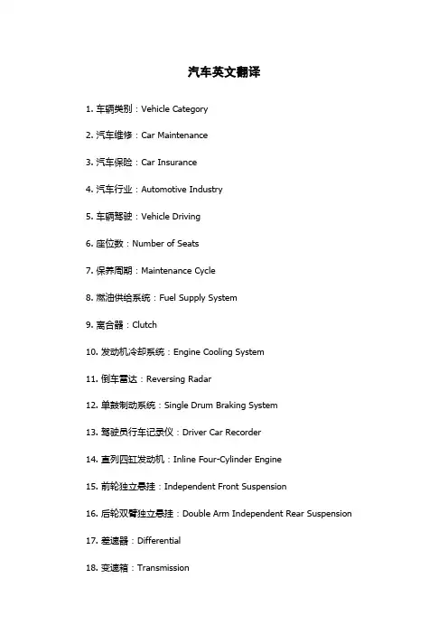
汽车英文翻译1. 车辆类别:Vehicle Category2. 汽车维修:Car Maintenance3. 汽车保险:Car Insurance4. 汽车行业:Automotive Industry5. 车辆驾驶:Vehicle Driving6. 座位数:Number of Seats7. 保养周期:Maintenance Cycle8. 燃油供给系统:Fuel Supply System9. 离合器:Clutch10. 发动机冷却系统:Engine Cooling System11. 倒车雷达:Reversing Radar12. 单鼓制动系统:Single Drum Braking System13. 驾驶员行车记录仪:Driver Car Recorder14. 直列四缸发动机:Inline Four-Cylinder Engine15. 前轮独立悬挂:Independent Front Suspension16. 后轮双臂独立悬挂:Double Arm Independent Rear Suspension17. 差速器:Differential18. 变速箱:Transmission19. 前轮驱动:Front-Wheel Drive20. 后轮驱动:Rear-Wheel Drive21. 前置发动机后驱:Front Engine Rear Drive22. 变速器智能控制系统:Intelligent Transmission Control System23. 发动机启停系统:Engine Stop-Start System24. 空气滤清器:Air Filter25. 过滤器:Filter26. 轮胎轮辋:Tire Rim27. 电池:Battery28. 玻璃:Glass29. 后视镜:Rearview Mirror30. 加油口:Fuel Filler Cap31. 后备箱:Trunk32. 灯光系统:Lighting System33. 倒车摄像头:Reversing Camera34. 后雨刷:Rear Wiper35. 左右倾角机:Lateral Inclination Machine36. 发动机排量:Engine Displacement37. 刹车制动系统:Braking System38. 自动泊车辅助系统:Automatic Parking Assistance System39. 动力转向系统:Power Steering System40. 防抱死刹车系统:Anti-Lock Braking System41. 门窗系统:Door and Window System42. 安全气囊:Safety Airbag43. 导航系统:Navigation System44. 声音系统:Sound System45. 车辆管制系统:Vehicle Control System46. 车代表键:Car Delegate Key47. 車輪充气壓力指示器:Tire Pressure Indicator48. 卫星导航:Satellite Navigation49. 视野系统:Viewing System50. 舒适设施:Comfort Facilities51. 蓄电池:Storage Battery52. 后视摄像头:Rearview camera53. RPM-table:A tachometer54. 排量:Displacement55. 排气量:Displacement56. 发动机:Engine; Motor57. 发动机室:Engine Room58. 燃料泵:Fuel Pump59. 灯泡:Light Bulb60. 行车记录仪:Driving Recorder61. 路况:Road Conditions62. 防爆窗:Bulletproof Glass63. 拨号系统:Dialing System64. 前光驱:Front Wheel Drive65. 合成油:Synthetic Oil66. 后刹车阻力:Rear Braking Resistance67. 后桥承载力:Rear Axle Load Capacity68. 发动机输油管:Engine Fuel Pipe69. 杜邦漆面抛光净化剂:DuPont Paint Polishing Purifier70. 视线范围:Line of Sight Range71. 充电器:Charger72. 卡车内饰:Truck Interior73. 步行者防护装置:Pedestrian Protection Device74. 侧向碰撞保护装置:Lateral Impact Protection Device75. 行李箱开启方式:Trunk Opening Method76. ABSS、ABS、ABS系统:Anti-lock Braking System(防抱死制动系统)77. 自动气控制系统:Automatic Air Control System78. 感应臂:Induction Arm79. 机油泵:Oil Pump80. 车身吸音棉:Body Sound-Absorbing Cotton81. 车身轻量化:Body Lightweight82. 车身扭转角:Body Torsion Angle83. 变速箱换档动力提升器:Transmission Shift Power Booster84. 氘气大灯:Deuterium Headlights85. 地图更新:Map Update86. 后置门边防撞杆:Rear Door Side Bump Strip87. 居住车:Residential Vehicle88. 车辆道路噪声测试系统:Vehicle Road Noise Testing System89. 操作手册:Operation Manual90. 刹车鼓:Brake Drum91. 发动机机油泵:Engine Oil Pump92. 减震器:Shock Absorber93. 转速表:Tachometer94. 自然通风系统:Natural Ventilation System95. 吸管:Straw96. 烟灰缸:Ashtray97. 倒闭式方向盘:Folding Steering Wheel98. 节能标书:Energy Saving Proposal99. 车辆电子电工程:Vehicle Electronics and Electrical Engineering 100. 车辆能耗:Vehicle Energy Consumption。
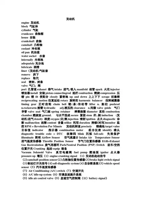
发动机engine 发动机block 气缸体cylinder 气缸crankcase 曲轴箱house 安装crankshaft 曲轴camshaft 凸轮轴coolant 冷却液oil pan 机油盘water socket 水套internally 内部地adequately充分地lubricate 润滑liner(发动机)气缸套remove 拆下replace 取代seal 密封,封条valve 气门;阀port 孔管道exhaust 排气intake 进气,吸入manifold 歧管spark 火花injector 喷油器install 安装piston connectingrod 连杆combustion 燃烧compression 压缩pin 销fit 使配合closely 紧密地up and down 上上下下scrape 活塞销reciprocating motion往复运动rotary 旋转的harmonic balancer 扭转减震器timing gear 正时齿轮chain belt链(条)传动带lifter n. 挺柱pushrod n.rockerarm摇臂hydraulic adj.液压的clearance n.间隙valve guide 气门导管valve seat 气门座spring retainer 弹簧座圈diameter 直径combustion chamber燃烧室ground. 与水平面成secure 紧固stem 杆,柄induction (发动机)进气density 浓度oxygen [化]氧injection 喷射ignition 点火diagnostic 诊断malfunction 故障content 含量utilize 利用duration 持续(时间)monitor 监控RPM = Revolution Per Minute 发动机转速precisely 精确地target value 目标值indicator 指示器combination meter 组合仪表identify 确认diagnostic trouble code = DTC 故障码blink 闪烁fail-safe 失效保护illuminate 照明Airflow Sensor 空气流量计Intake Air Temperature Sensor 进气温度传感器Throttle Position Sensor 节气门位置传感器EGR=Exhaust Gas Recirculation 废气再循环Park/Neutral Position (PNP) Switch 驻车/空挡位置开关Cranking 起动equip 装备Vacuum Solenoid Valve 真空电磁阀fuel pump 燃油泵igniter 点火器pressure up 增压(1)engine cranking signal (1)发动机起动信号(2)camshaft position sensor(2)凸轮轴位置传感器(3)brake light switch signal (3)制动灯开关信号(4)self-diagnostic system(4)自诊断系统(5)vehicle speed sensor(5)汽车速度传感器(7)Air Conditioning (A/C) switch(7)空调开关(8)A/C idle-up system(8)空调怠速提升系统(9)idle air control valve(9)怠速空气控制阀(11)battery signal)蓄电池信号(12)1)Airflow Sensor(1)空气流量计(3)Engine Coolant Temperature Sensor(3)发动机冷却液温度传感器(4)Crankshaft Position Sensor(4)曲轴位置传感器(5)Knock Sensor(5)爆震传感器(7)Atmospheric Pressure Sensor(7)大气压力传感器(8)Intake Air Temperature Sensor(8)进气温度传感器10)Air Condition Compressor10)空调压缩机Bolt 螺栓water jacket 水套radiator 散热器,水箱water pump 水泵thermostat 节温器fan风扇9-nut(螺母)12-O ring(O型圈)15- seal(密封圈) 16– drain screw(排水螺栓)assist 帮助relief valve 泄压阀vacuum valve 真空阀negative pressure 负压timing belt正时皮带load 负荷lubrication润滑supply 供给oil pan 油底盘drain 排放draw 抽吸1-gasket(密封垫片)2-cap(加油口盖)3-dipstick(机油标尺)4–guide(机油标尺导管口)6-oil pressure switch(机油压力开关)8-oil cooler(机油冷却器)9-oil filter(机油滤清器)10-cap(密封盖)12-gears(齿轮)15-oil drain plug(放油螺栓)16-seal(密封圈20- Oring(O形圈contaminant 污染物trap 大功率gasoline汽油diesel 柴油sense 感觉dashboard (汽车等的)仪表板gauge 仪表dipstick 油尺(1)oil cooler(1)机油冷却器(2)gasoline engine (2)汽油机(3)fan ring(3)风扇罩壳(4)locking bolt(4)紧固螺栓(6)suction line(6)进油管(7)oil filter bracket(7)机油滤清器支架(8)2-pin connector (8)双头插式插头(9)radiator fan thermo switch(9)散热器风扇热敏开关(10)diesel engine10)柴油机(1)水套(1)Water jacket(2)水泵(3)Radiator cap(4)真空阀4)Vacuum valve(5)机油泵5)Oil pump(6)机油滤清器(6)Oil filter voltage 电压,伏特数electrical current电流automobile 汽车alter 变化semiconductor半导体Transistor晶体管1-battery (蓄电池)2-ignition switch (点火开关) 3-ignition coil (点火线圈) 4-distributor (分电器) 5-spark plug(火花塞) 8- ECM (电子控制模块)ground 接地.搭铁monitor 监控deliver 传递2-dustproof cover(防尘罩) 4-rotor (转子) solenoid电磁开关field 磁场pole 电极brush 电刷1- battery (蓄电池) 2- starter (起动机) relay 继电器) 4- ignition switch (点火开关)switch 转换circuit 电路charge 充电alternator发电机adjust 调节instrument panel仪表板cable电缆harness线束resonator进气谐振腔high–tension cord高压线cutout 切口coupling连接器burning out烧毁perform 执行(4)cranking motor(4)起动机(6)TDC(6)上止点(7)high–tension cord(7)高压线(4)Firing order(4)点火顺序(7)Charge indicator7)充电指示灯Engine Control Module发动机控制模块procedure 程序service manual维修手册reference参考symptom症状misdiagnosis 误诊simulation 模拟reproduce复制chart图表matrix chart检查表instruct 指示wire harness 线束adjustment调节neutral空挡tachometer转速表BDC下止点flash闪烁road test路试(2)warm up(2)暖机(3)switch off (3)断电;熄火(5) combination meter (5) 组合仪表(6)malfunction code(6)故障码1)engine operating temperature(1)发动机工作温度(3)battery negative terminal(3)蓄电池负极(5)road test(5)路试clutch离合器transmission 变速器lessen减少1- flywheel(飞轮)5- transaxle(驱动桥)constant mesh常啮合direct drive直接挡synchro adj.同步circumference 环境power flow 动力传动路线deceleration减速overdrive超速挡manufacturer生产厂7- oil pan(油底壳45- oil pump(油泵)46- oil pump gasket(油泵衬垫58- brake plate(制动盘)59- brake disc(制动片special tool专用工具immerse浸入sealant密封胶adhesive粘合剂vinyl乙烯树脂nylon尼龙(2)pressure plate(2)压盘(5)power flow(5)动力传动路(8)torque converter(8)液力变矩器suspension悬挂stability稳定characteristics性能turning corners转弯severity 强度oscillation震动differential差速器tubular-steel钢管universal joints万向节) torsion扭转traction牵引力1- pinion gear(行星齿轮) vise虎钳backlash.侧隙run out摆振race座圈Mating marks装配记号diagonal对角线multi- purpose grease 润滑脂adhesive粘合剂adhered to粘着,粘附threaded holes螺纹孔(1)universal joint(1)万向节(2)suspension system(2)悬架系统(4)gear backlash (4)齿轮侧隙6 non independent suspension(6)非独立悬架2- brake pedal(制动踏板4- brake tubing(制动管路)pad块shoe蹄片lock-up抱死release释放stoplight停车灯booster助力器1- ABS sensor(ABS传感器)3- sensor传感器)8- ABS warning light(ABS警告灯)9- brake warning light(制动警告灯)10- data link connector(数据通讯连接器)11- ECU(电子控制单元)modulator调节器momentarily即刻Incipient初期的2- guide pin(导向销)3- caliper support(制动钳支架)4- boot(橡胶衬套)5- bushing(套管)6- piston boot(活塞防尘罩)7- piston(活塞)8- piston seal(活塞密封圈)9- caliper body(制动钳体)10- pad and wear indicator assembly(制动块和磨损指示总成)11- pad assembly(制动块总成)手锤protrude 螺丝起子uneven不稳Limit value极限值(1)盘式制动器(1)disc brake(2)主缸(2)master cylinder (4)轮缸(4)wheel cylinder(5)滑动摩擦(5)sliding friction(6)驻车制动器6)parking brake(7)制动防抱死系统(7)ABS(8)制动钳(8)caliper body (2)brake booster(2)制动助力器(5)brake fluid(5)制动液(8)drum brake(8)鼓实制动器steering knuckle转向节1- frame (车架)7- pitman arm (转向摇臂)15- worm gear(蜗轮)16- housing(壳体)17- shim (垫片)integral整体的actuate 驱动fatigue疲劳slipper滑块1- oil outlet (出油口) 2- oil inlet (进油口) 11- cylinder head (缸盖) 12- worm shaft (蜗杆轴) 13- pitman arm (摇臂) rack齿条tap敲击Stopper 限位块brass bar 铜棒needle roller bearing 滚针轴承1)steering linkage(1)转向传动机构(3)steering knuckle(3)转向节(4)tie-rod(4)横拉杆(1)power steering(1)动力转向(2)steering knuckle(2)转向盘(3)steering column(3)转向柱(8)steering gear(8)转向器range区域abnormality反常item项目solenoid valve电磁阀power train 动力传动系initially 初始occurrence 发生scan tool 扫描仪start up起动start-up screen 起动屏MITSUBISHI三菱data list数据流logic 逻辑(2)power-train control module(2)动力系控制模块(3)battery terminal(3)蓄电池接柱(4)ignition switch(4)点火开关5)start-up screen(5)起动屏幕(4)erase DTC(4)删除故障码damage损伤reminder提示worn损坏的brake pads 制动蹄片dealer特约维修店buzzer蜂鸣器beeper喇叭boot行李箱burned out熄灭hazard危险illuminate照明RESUME复位airbag气囊alert警示tachometer转速表(1)洗涤液(1)wash fluid(4)几秒钟(4)a few seconds (5)行驶(5)in motion(6)系紧安全带(6)fasten seat belt(7)防抱死系统(7)anti-lock brake system(8)制动液面(8)brake fluid level(9)巡航控制(9)cruise control system(10)按下设置和复位按钮(10)press SET andRESUME button1)tail light(1)尾灯fuel gauge(3)燃油表(5)headlamp (5)前照灯(6)hazard warning indicator(6)危险警告指示灯(7)speedometer and odometer (7)车速里程表(8)low oil pressure(8)低油压指示灯(9)turn signal light(9)转向信号灯(10)self-diagnosis(10)自诊系统compressor 压缩机condenser冷凝器receiver贮液干燥器evaporator蒸发器expansion valve 膨胀阀amplifier放大器refrigerant制冷剂deplete消耗ozone layer臭氧层ultraviolet紫外线suck吸气dissipate消散1- compressor (压缩机)2- low-pressure side (低压侧)3- high-pressure side (高压侧)4- expansion valve (膨胀阀)11- electric fan (电风扇)evaporate蒸发power transistor功率晶体管blower motor风扇电机amplifier放大器precaution小心handle处理enclosed封闭的Apply涂,抹petroleum jelly凡士林physician医生drop扔掉moisture 潮气wrench 扳手burnout 烧坏rupture 破坏(5)poisonous gas(5)毒气(7)ambient temperature sensor(7)环境温度传感器(1)air conditioning system(1)空调系统(2)input signal(2)输入信号(3)output signal(3)输出信号(4)blower motor(4)鼓风机马达(5)air flow volume(5)气流量(8)power transistor8)功率晶体管(9)compressor magnetic9)压缩机电磁离合器(10)wiper雨刮器washer洗涤器supply提供operate工作windshield风挡玻璃intermittent间歇BCM车身控制模块feature性能via经,由data-line数据线trim装饰物unlocked打开automatic自动的all the way一直knob按钮integrated集成的initiate 触发disabled失效的(2)door courtesy light (2)门控灯(4)remote control mirror(4)遥控镜(5)rear window defogger (5)后窗除雾器(6)fog and back-up light6)雾灯和倒车灯(7)luggage compartment light(7)行李箱室内灯(8)intermittent operation(8)间歇操作(9)sub/main switch(9)主/副开关(1)wiper relay1)雨刮继电器(2)rear combination light(2)后组合灯(3)speed sensor(3)车速传感器(4)license plate light(4)牌照灯(5)washer motor(5)洗涤电机hood罩盖luggage compartment lid(车身)行李箱盖disarmed(防盗)解除的multi-remote controller 遥控器disconnect断开anti-theft alarm syste防盗报警系统interrupt切断tampered干扰trunk lid行李箱盖deactivate撤销procedure程序Imprint 记号priority优先权(5)完成(5)carry out(9)行李箱盖(9)luggage compartment lid(2)engine hood(2)发动机盖(3)luggage compartment lid(3)行李箱盖(5)turn off(5)关闭(6)anti-theft alarm system6)防盗报警系统(7)security indicator(7)安全指示灯(8)unlock door(8)打开门锁(9)multi-remote(9)识别码interpret翻译1- terminal box No.1(1号接线盒)2- ignition switch(点火开关)4- cruise control switch(巡航控制开关)5- parking brake switch(驻车制动开关)6- parking light switch(停车灯开关)7- clutch switch(离合器开关)9- brake fluid level warning light switch(制动液液位警告灯开关)10- neutral drive switch (NDS)(空挡起动开关)over rev超速RPM每分钟转速in series串联ft. 英尺MPH=miles per hour时速canister容器ACCEL 加速COAST滑行erase清除jack 千斤顶lift 升降器Adaptive 自适应的enhancement 提高conventional 传统的appropriate合适的radar 雷达clearance间距autonomously 自动地(1)巡航控制系统1)cruise control system (2)设定速度(2)set speed(3)数字信号(3)digital signal(6)车速传感器(6)vehicle speed sensor(7)加速踏板(7)accelerator pedal(8)变速杆(8)shift level(9)本词汇为汽车中常用的常用词汇,作者第一次编写,难免有错误或者不当之处,希望大家提些宝贵意见,多多的交流,谢谢本文由汽车车位锁网整理。
汽车维修中英文对照表 Document serial number【KKGB-LBS98YT-BS8CB-BSUT-BST108】汽车维修专业术语的英语对照表1汽车维修养护专业英语对照表,学汽车维修的英语都不太好,搞来个对照表可参考一下.汽车维修管理AdministrationofVehicleMaintenance汽车维护方法Methodofvehiclemaintenance汽车维护流水作业法Flowmethodofvehiclemaintenance汽车维护定位作业法Methodofvehiclemaintenanceonuniversalpost汽车修理方法Methodofvehiclerepair汽车修理流水作业法Flowmethodofvehiclerepair汽车修理定位作业法Methodofvehiclerepaironuniversalpost总成互换修理法Unitexchangerepairingmethod周转总成Reversible?unit混装修理法Depersonalizedrepairmethod就车修理法Personalizedrepairmethod汽车维修指标Indicesofvehiclemaintenanceandrepair汽车维护生产纲领Productionprogramofvehiclemaintenance汽车修理生产纲要Productionprogramofvehiclerepair汽车维修周期Periodofvehiclemaintenance汽车诊断周期Periodofvehiclediagnosis汽车维修竣工辆次Numberofvehiclebeingreceivedfrommaintenanceorrepair汽车大修平均在厂车日Averagedaysinplantduringmajorofvehicles汽车大修平均在修车日Averagedaysduringmajorrepairofvehicles汽车大修平均工时Averageman-hoursofvehiclemaintenanceandrepair汽车维修平均费用Averagecostsofvehiclemaintenanceandrepair汽车大修返修率Returningrateofmajorrepairofvehicle汽车小修频率Frequencyofcurrentrepairofvehicles汽车大修间隔里程Averageintervalmileageofmajorrepairofvehicles汽车修理工人实物劳动生产率Labourproductivityofrepair-man汽车维护企业Enterpriseofvehiclemaintenanceandrepair汽车维护场(站)Maintenancedepot(station)ofvehicles汽车停车场(库)Park汽车修理厂Vehiclerepairplant汽车总成修理厂Unitrepairplantforvehicle汽车诊断站Vehiclediagnosisstation汽车检测站Detectingteststationofvehicle汽车维修网点Networkofvehiclemaintenanceandrepair汽车维修工具和设备InstrumentandDeviceforVehicleMaintenanceandRepair螺丝刀Screwdriver花扳手Ring?spanner锉刀File双头扳手Double-ended?spanner鲤鱼钳Combination?pilers轮胎螺栓扳手Wheel?wrench厚度规Feeler?gauge杆式气缸量规Bar-typecylindergauge气缸压力表Cylindercompressorgauge活塞台钳Piston?vice活塞加热器Piston?heater活塞环工具Pistonringtool活塞环钳(活塞环拆装钳)Pistonringpliers(pistonringtongs)压环器Pistonringcompressor活塞环锉Pistonringfile活塞销拉器Piston-pin?extractor连杆校正器Connectingrodalignmentfixture气门座刀具Valveseatcutter气门弹簧压缩器Valvespringcompressor气门研磨工具Valvegrindingtool(valvelapper)调整气门间隙扳手Tappet?wrench浮子室液面仪Floatlevelgauge歧管压力表Manifoldpressuregaugeset点火正时灯(正时观测灯)Ignitiontiminglight(stroboscope) 燃烧分析仪Combustion?tester断电器触点闭合角Dwell?meter火花塞间隙量规Pluggapgauge火花塞套筒扳手Sparkplugbox(socket)spanner蓄电池液体比重计Battery?hydrometer汽车架Carstand(jackstand)轮轴架Axle?stand前束量尺Toe-in?gauge外倾测量器Camber?gauge制动踏板压下器Brake?depressor制动器放气软管Hoseforbrakebleeding车架量规Frame?gauge轮毂拆卸器Hub?puller车轮拆卸器Wheel?wrench拆装轮胎用撬杠Tire-lever打气筒Tire?pump螺旋千斤顶Screw?jack轮胎压力计Pressure?gauge油壶Oil?can手油泵Manualfuelpump黄油枪Grease?gun起动摇把Starting?crank工具袋Tool?bag车身修整工具Bodybumpingtool发动机测功机Engine?dynamometer发动机综合试验机Engine?analyzer发动机示波器Enginescope(oscillograph)电子诊断式发动机试验仪Electronic-diagnosticenginetester 滚筒式测功试验台Rollertypedynamometer(testbed)发动机加速测功仪Freeaccelerationenginetester容积式油耗计Volumetricfuelmeter红外线废气分析仪Infraredraysexhaustgasanalyzer异响诊断仪Abnormalenginenoisediagnosisequipment气缸漏气率检验仪Cylinderleaktester发动机分析仪Engineanalysisapparatus进气歧管真空度表Intakemanifoldvacuummeter气缸压力表Cylinderpressuregauge调整用的试验检测仪Tune-up?tester底盘测功机Chassis?dynamometer底盘润滑机Chassis?lubricator曲轴箱窜气量测定仪Blow-by?meter反作用力制动试验台Reactiontypebraketester惯性式制动试验台Inertiatypebraketester转向盘间隙测量仪Steeringwheelfreeplaygauge测滑试验台Side-slipcheckingstand前照灯检验仪Headlightcheckingequipment气缸孔垂直检验仪Cylinderperpendicularitygauge主轴承座孔同轴度检验仪Mainbearingaligninggauge移动式车轮平衡机Portablewheelbalancer固定式车轮平衡机Wheel?balancer车轮动平衡机Dynamicwheelbalancer镗缸机Cylinderboringmachine气缸珩磨机Cylinderhoningmachine直线镗削机Line?borer气门修整机Valve?reseater(活塞)销孔珩磨机Pinhole?honer曲轴磨床Crankshaftgrindingmachine气门研磨机Valvegrindingmachine气门面磨光机Valve?refacer气门座磨光机Valveseatgrinder气门座偏心磨光机Eccentricvalveseatgrinder研磨机Lapping?machine电子点火试验器Electronicignitiontester点火线圈试验器Ignitioncoiltester氖管火花试验器Neonsparktester电容器试验器Condenser?tester电枢试验器Armature?tester制动盘专用车床Disc?lathe制动蹄片磨削装置Brakeshoegrinder制动鼓车床Brakedrumlathe制动液自动更换装置Brake?flusher(液压)制动系空气排除器Brake?bleeder汽车维护Vehicle?maintenance汽车修理Vehicle?repair汽车维修制度Systemofvehiclemaintenanceandrepair汽车维修性Maintainabilityofvehicle汽车技术状况TechnicalConditionofVehicle汽车完好技术状况Goodconditionofvehicle汽车不良状况Badconditionofvehicle汽车工作能力Workingabilityofvehicle汽车技术状况参数Parametersfortechnicalconditionofvehicle汽车极限技术状况Limitingconditionofvehicle汽车技术状况变化规律Regularityforchangeoftechnicalconditionofvehicle 运行缺陷Operational?defect制造缺陷Manufacturing?defect设计缺陷Design?defect事故性缺陷Accidental?defect汽车耗损Vehicle?wear-out汽车零件磨损Wearofvehiclepart磨损过程Wear?process正常磨损Normal?wear极限磨损Limiting?wear允许磨损Permissible?wear磨损率Wear?rate机械磨损Mechanical?wear化学损耗Chemical?wear热磨损Thermic?wear疲劳磨损Fatigue?wear腐蚀性磨损Corrosion?wear故障磨损Failure?wear故障Malfunctioning断裂Breakdown损坏Damage汽车维修专业术语的英文对照表2更换(零件)Replacing擦伤Scratching刮伤Scoring点蚀Pitting粘附Adhesion咬粘Seizure烧伤Burning穴蚀Cavitation老化Aging疲劳Fatigue变形Deformation缺陷Defect汽车故障Vehicle?failure完全故障Complete?failure局部故障Partial?failure致命故障Critical?failure严重故障Major?failure一般故障Minor?failure汽车故障现象Symptomofvehiclefailure抢气Mixture?robbery呛油Fuel?fouling盘车Turning飞车Run?way工作粗暴Rough?running早燃Preignition回火Back?fire自燃现象Dieseling(afterrun)爆震(爆燃)Detonation火花(点火)爆燃Spark?knock燃料爆燃Fuelknock(gasknock)不发火(不点火)Misfiring调速不匀Hunting过度停顿Flat?spot调速器工作不匀Governor?hunting回流Backflow窜气Blow-by稀释Dilution滤清器阻塞Clogged?filter润滑超量Overlubrication(气缸)上油Oil?pumping(柴油喷射系)渗漏滴油After?dripping (燃料系)气阻Vapor?lock结胶Gum?deposit敲缸Knock拉缸Cylinder?score咬缸Cylinder?sticking轴颈擦伤Journal?score刮伤Scuff拉瓦Bearing?score(化油器)汽湿现象Percolation化油器结冰Carburetor?icing活塞敲缸Pistonknock(pistonslap)活塞裙部挤扁Collapseofpistonskirt气门挺杆发响Tappetnoise(valveknock)气门弹簧颤动Valvespringsurge(蓄电池)硫化Sulphation(蓄电池)过度放电Over?discharge(火花塞)铅沉积Lead?fouling(火花塞)积碳Carbon?fouling真空提前失效Defectivevacuumadvance高压线跳火错乱Secondarywirecrossfiring 转向反冲Steering?kickback离合器炸裂Clutch?explosion制动踏板发软Spongybrakepedal制动踏板费力Hard?pedal制动器发响Noisy?brake制动踏板过低Lowbrakepedal制动盘摆动Disc?runout制动失效Brake?fade减振器失效Defectiveshockabsorber轮胎烧耗Burn?rubber轮胎急速磨耗Peel?rubber漂滑效应Hydro-planning(aqua-planning)(由于紧急制动)紧急滑行Impending?skid充气不足Under-inflation异响Abnormal?knocking泄漏Leakage过热Overheat失控Outofcontrol乏力Lackofpower污染超限Illegalexhaustandnoise费油Excessiveconsumptionoffuelandoil振抖Fluttering故障率Failure?rate平均故障率的观察值Observedmeanfailurerate故障树型分析法Faulttreeanalysis汽车维护类别Classofvehiclemaintenance定期维护Periodic?maintenance季节性维护Seasonal?maintenance技术保养Technical?service清洗Washing技术检查Check-up保养周期Service?cycle保养里程Mileagebetweenservices每日保养Daily?service防护Preserving冬季保养Winter?check-up夏季保养Summer?check-up走合维护Running-in?maintenance汽车修理类别Classofvehiclerepair汽车大修Majorrepairofvehicle汽车中修Mediumrepairofvehicle汽车小修Currentrepairofvehicle总成修理Unit?repair零件修理Parts?repair计划修理Scheduled?repair定期修理Regulating?repair视情修理Repairontechnicalcondition非计划修理Unscheduled?repair修复Reconditioning修理里程Mileagebetweenrepair拆开Separating拆下Withdrawing拆卸Disassembling校正Aligning装配Fitting重新装配Reassembling调整Adjusting单独修理Individual?repair汽车报废Motorvehicleliquidation报废Scrapping汽车维护工艺TechnologyofVehicleMaintenance汽车维护作业Operationofvehiclemaintenance汽车维护工艺过程Technologicalprocessofvehiclemaintenance 汽车修理工艺Technologyofvehiclerepair汽车修理工艺过程Technologicalprocessofvehiclerepair技术检验Technical?checking检视Inspection?零件检验分类Inspectionandclassificationofparts走合,磨合Running-in冷磨合Cold?running-in热磨合Hot?running-in修理尺寸Repair?size走(磨)合期Running-in?period走(磨)合过程Running-in?process走(磨)合工况Running-in?conditions加速磨损期Periodofacceleratedwear极限间隙Limiting?clearance允许间隙Permissible?clearance装配间隙Assembling?clearance汽车维修工艺设备Technologicalequipmentofvehiclemaintenanceandrepair 汽车修理技术标准Technicalstandardofvehiclerepair汽车诊断Vehiclediagnosis汽车检测Detectingtestofvehicle诊断参数Diagnostic?parameters诊断规范Diagnostic?norms汽车维修专业词汇中英文对照表3散热器芯radiator?core之字形管散热器芯film?core管-片式散热器芯finandtubecore散热器加水口盖radiatorfiltercap压力式水箱盖radiator-pressure?cap蒸气-空气泄放阀vapor-airreleasevalve散热器护罩radiator?cowl散热器百叶窗radiator?shutter散热器保温帘radiatorrollerblind散热片cooling?fin缸盖散热片cylinderheadfin缸体散热片cylinderblockfin控温装置temperatureregulatingdevice恒温器thermostatthermostatmainvalve恒温器旁通阀thermostatby-passvalve恒温器挠性波纹筒thermostatflexiblebellows 液体冷却设备liquidcoolingequipment水泵water?pump水泵体pumpcasing水泵叶轮waterpumpimpeller旁通进水口waterby-passinletneck循环泵circulating?pump主进水口watermaininletport出水口wateroutletport自调式水封self-adjustingsealunit溢流管overflow?pipe导流板deflector风扇fan(blower)轴流式风扇axialflowfan离心式风扇centrifugal?fan风扇壳体blower?casing风扇导流罩fan?cowl风扇毂fanhub风扇叶片fan?blade风扇叶轮blower?impellerblower?stator风扇皮带轮fan?pulley三角皮带v-belt风扇护罩fan?shroud风扇叶轮叶片impeller?vane冷却用空气cooling?air风扇导流叶片stator?vane强制风冷forced-air?cooling自然风冷naturalaircooling风道air?ducting润滑系lubrication?system润滑lubrication气缸上部润滑uppercylinderlubrication 压力润滑pressure-feedlubrication 压力润滑法forcedlubrication自动润滑automaticlubrication飞溅润滑splashlubrication润滑周期lubricationinterval边界润滑borderlinelubrication曲轴箱机油油盘crankcaseoilpan油底壳oil?pan机油盘放油塞sump?plug集油器oil?collector机油泵oil?pump计量式机油泵meteringoilpump齿轮式机油泵geartypeoilpump转子式机油泵rotor-typeoilpump机油泵出油管oilpumpoutletpipe放油口oildrainhole油道oil?duct断油开关cut-off?cock机油散热器oil?cooler机油滤清器oil?filter机油粗滤器primaryoilfilter机油精滤器secondaryoilfilter全流式机油滤清器full-flowoilfilter分流式机油滤清器by-passoilfilter离心式机油滤清器centrifugaloilfilter整体式滤芯integralfilteringelement 细滤器滤芯filter?element滤清器壳filter?box滤片filtering?disc机油减压器oilpressurereliefvalve 旁通阀by-passoilfilteroil?strainer加机油孔oilfiltercap滤芯轴filter?shaft刮片组件cleaning?edge机油量尺dipstick机油滤网oil?strainer增压器supercharger增压和扫气装置pressure-chargingandscavengingunit 增压装置supercharging?device汽车维修专业词汇中英文对照表4加机油孔tank-mountedeletricfuelpump机械式燃油泵mechanicalfuelpump膜片式燃油泵diaphragmfuelsupplypump叶片式供油泵vanefuelsupplypump活塞式输油泵pistontypefuelsupplypump齿轮式输油泵gearfuelsupplypump电动燃油泵eletricfuelpump带真空泵的汽油泵vacuumpumpwithfuelpump起动加油器primer起动给油杆primer?lever燃油泵上体fuelpumpbody燃油泵下体fuelpumpbase燃油泵盖进油口接头fuelinletneck出油口接头fueldischargeport输出阀delivery?valve泵油元件pump?element回油阀部件fuelreturnvalveassembly化油器carburetor化油器系统carburetor?circuit简单化油器elementary?carburetor单腔化油器single-barrel?carburetor双腔并动化油器two-barreldualcarburetor双腔分动化油器two-barrelduplexcarburetor四腔化油器four-barrel?carburetor上吸式化油器updaught?carburetor下吸式化油器downdraught?carburetor平吸式化油器horizontal?carburetor侧吸式化油器side-draft-carburetor高海拔补偿式化油器altitudecompensatingcarburetor 化油器附加器adaptor?carburetor双腔式化油器twin-choke?carburetor固定喉管式化油器fixedventuricarburetor可变喉管化油器variableventuricarburetor化油器接头carburetor?adaptor阻风门choke?valve阻风活塞choke?piston阻风板choke?plate自动阻风门automatic?choke阻风门拉钮choke?button电控自动阻风门electric-assisted?choke 阻风管choke?tube喉管venturi双重或三重喉管double&tripleventuri阻风门拉线choke?cable化油器小喉管booster?venturi浮子系float?system浮子float环形浮子annularfloat同心式浮子concentric?float浮子支销floathingepin浮子针阀floatneedlevalve阀针valve?needle浮子油面float?level浮子臂float?arm侧置浮子室式sidefloattype怠速阀怠速针阀idle?needle省油器economizer省油器阀economizer?valve辅助空气阀auxiliary?air-valve加速油井accelerating?well加速泵accelerating?pump加速泵喷嘴acceleratingpumpnozzle 油门throttle手油门hand?throttle节气门操纵手柄throttlecontrollever 真空加浓器vacuum?booster加浓器excessfueldevice量孔体jet?block怠速量孔idlemeteringjet主量孔mainmeteringjet剂量阀活塞dosagevalvepiston空气量孔air?jet燃油滤清器fuel?filter沉淀杯sediment?bowl串联过滤器in-line?filter燃油箱内装过滤器in-tank?filter调速器飞球式调速器flyball?governor调速器governor飞球式调速器flyball?governor液压调速器hydraulic?governor真空转速调速器vacuumspeedgovernor惯性调速器inertia?governor离心调速器centrifugal?governor调速器重锤governor?weight空气滤清器及进排气系统aircleanerandintakeandexhaustsytem 空气滤清器air?filter冲压式空气滤清器ramairclearner恒温控制式空气滤清器thermostaticcontrolledaircleaner 油浴式空气滤清器oilbathaircleaner纸质空气滤?清器paperairclearner旋流管式空气滤清器swirltubeairfilter滤清器滤芯filter?element空气滤清器壳体airfilterhousing空气滤清器盖airfiltercover滤清器密封圈filtersealring滤网sieve滤纸盘或膜filterpaperdiscormembrane进气和排气系统intakeandexhaustsystem排气管exhaust?pipe排气抽气管exhaustextractionduct扫气泵scavenging?pump进气预热装置intake?preheater进气歧管intake?manifold进气歧管真空度intakemanifoldvacuum冷式进气歧管cold?manifold冲压式进气歧管ramintakemanifold排气歧管exhaust?manifold脉冲式排气歧管pulseexhaustmanifold等压排气歧管constantpressrueexhaustmanifold 排气歧管热量控制阀exhaustmanifoldheatcontrolvalve 超高度歧管high-rise?manifold升温横跨管道heat?crossover排气横跨管道exhaust?crossover预热点hot?spot阻风门加热器choke?heater热空气导流管hotairduct隔热板heat?shield排气再循环阀exhaust-gas-recirculation消声器silencer进气消声器intake?silencer排气消声器exhaust?silencer金属垫片式消声器steelpackmuffler玻璃丝消声器glasspackmuffler空洞消声器gutted?muffler前排气管frontexhaustpipe尾管tail?pipe消声器联接管intermediate?pipe热空气管hotairpipe曲轴箱通风管crankcasebleedpipe隔声罩acoustic?hood进气消声器元件silencer?element真空泵vacuum?pump指示功率indicated?power指示热效率indicatedthermalefficiency指示油耗率indicatedspecificenergyconsumption 示功图indicator?diagram冷却系cooling?system风冷air?cooling水冷water-cooling循环流冷却系coolingrecoverysystem自然循环液冷却系统naturalcirculationtypecoolingsystem 热流循环液冷却系统thermo-siphoncirculationtypecoolingsystem 温差循环液冷却系统gravitycirculationwatercoolingsystem压力式水冷却系统positivecirculationcoolingsystem加压式冷却法pressuretypecooling水泵循环冷却系统pumpcirculationcoolingsystem强制循环式化冷系统forced-feedwatercirculationsystem封闭式液冷系统sealedcoolingsystem散热器radiator片式散热器finned?radiator管式散热器tubular?radiator蜂窝式散热器cellular?radiator哈里逊式散热器Harrisontyperadiator带板式散热器ribbontyperadiator上水箱upper?tank下水箱lower?tank涨溢箱expansion?tank。

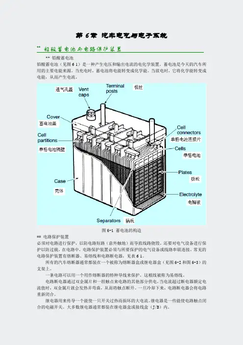
第6章汽车电气与电子系统** 铅酸蓄电池与电路保护装置** 铅酸蓄电池铅酸蓄电池(见图6-1)是一种产生电压和输出电流的电化学装置。
蓄电池是今天的汽车所用的主要电能来源。
当充电时,蓄电池将电能转变成化学能。
当放电时,它将化学能转变成电能,从而产生电流。
图6-1 蓄电池的构造** 电路保护装置必须对电路进行保护,以防电路短路(意外触地)而导致线路烧毁。
还要对电气设备进行保护以防过载。
在电路中,电路保护装置必须与所要保护的电气设备或线路串联连接。
常见的电路保护装置有熔断器、易熔线和电路断电器,见表6-1。
所有的汽车熔断器通常都装在一个被称为熔断器盒或继电器盒(见图6-2和图6-3)的支架上。
一条电路可以用一个用作熔断器的特种导线来保护。
这根线被称为易熔线。
电路断电器通过双金属片和一组触点来电路的其他部分供电。
当电流超过断电器额定电流值时,双金属片就会发热并弯曲,从而将触点断开。
一旦冷却下来,电路断电器会将电路重新闭合。
继电器用来传导一个能使一只开关过热而损坏的大电流。
继电器是一些能使电路触点闭合的电磁开关。
大多数继电器通常都装在继电器盒或接线盒(J/B)内。
表6-1 丰田汽车电路图所用的电路保护装置Illustration 图Symbol 符号Name 名称Abbraviation缩写Fuse熔断器FuseMedium current fuseM-Fuse中电流熔断器High current fuseH-Fuse大电流熔断器Fusible linkFL易熔线Circuit breakerCB电路断电器Array图6-2 熔断器盒、继电器盒和接线盒在乘用车上的位置图6-3 一辆厢式车的熔断器盒、继电器盒和接线盒的位置** 充电系统充电系统利用发动机的转动来发电,以便给蓄电池充电和提供操作各种汽车电气系统所需的电能。
现代汽车充电系统的组成包括发电机和电压调节器(见图6-4和图6-5)。
图6-4 典型的交流发电机图6-5 一台典型的交流发电机(带电压调节器)零件分解图** 起动系统现代内燃机都利用电起动机来起动。
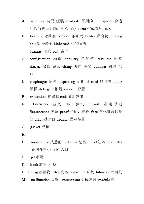
A assembly 装配组装available可用的appropriate 合适的恰当的axis轴,中心alignment排成直线assyB bending弯曲度barcode条形码binder黏合物bindingbolt紧固螺栓biohazard 生物危害bearing 轴承belt 带子C configuration构造capillary毛细管calculate 计算chassis底盘底架clamp 夹住夹紧cylinder 圆筒汽缸D diaphragm隔膜dispensing分配discard废弃物dilute稀释defergent推迟diode二极管E expansion 扩张物emit放出发出F fluctuation波动float飘动formula准则原则fluorescence荧光proof论证,校样fuse溶化融合保险丝filter过滤器fixture 固定装置G gasket 垫圈HI immature未成熟的inductive感应inject注入internally在内在中心inlet入口J jet喷嘴K knob旋钮小块L leakag渗漏物latex乳胶logarithm对数lubricant润滑剂M malfunction故障mechanism机械装置module单元N nozzel管嘴, 喷嘴O obstacles障碍妨碍optical 光学的P pinch夹piercer钻孔器perform执行partical零件的pneumatic风动的peak顶photodiode 光电二极管plate 盘子镀pulley滑轮prism棱柱棱镜piston 活塞Q quantity数量R replenish 补充rotation旋动remote微小的relief解除减轻resistant有抵抗力的S stability稳定性稳固shield护罩防护物syringe注射器semiconductor半导体spot点scatter散开separate隔离的solenoid螺线管shoe金属箍snap (使某物)发出尖厉声音地突然断裂[打开, 关闭] spout管口喷口screw螺丝shrink 收缩silicone 硅spacer 逆电流器T thermal热的,热量transducer传感器thermister电热调节器shape 外形样子seal 密封封条shaft 杆轴solder 焊接焊锡sponge海绵U uniformity无差异无变化的utilize利用使用V via经由W wiring线路XYZ。
The 1.4l TSI* engine is the world’s first petrol engine with direct petrol injection and dual-charging. Volkswagen is thus laying another milestone in engine development.* The term “TSI” is a protected abbreviation of Volkswagen.S359_002On the following pages, we will introduce you to the design and function of the new 1.4l TSI engine with dual-charging.Introduction . . . . . . . . . . . . . . . . . . . . . . . . . . . . . . . . . . . . . . . . . . . . . . . . . . 4Engine mechanics . . . . . . . . . . . . . . . . . . . . . . . . . . . . . . . . . . . . . . . . . . . . . . 6Poly-V-belt drive . . . . . . . . . . . . . . . . . . . . . . . . . . . . . . . . . . . . . . . . . . . . . . . . . 6Timing chain . . . . . . . . . . . . . . . . . . . . . . . . . . . . . . . . . . . . . . . . . . . . . . . . . . . . 7Cylinder block . . . . . . . . . . . . . . . . . . . . . . . . . . . . . . . . . . . . . . . . . . . . . . . . . . . 8Cylinder head and valve train . . . . . . . . . . . . . . . . . . . . . . . . . . . . . . . . . . . . 10Dual-charging with supercharger and turbocharger . . . . . . . . . . . . . . . . . 11 Crankcase breather and ventilation . . . . . . . . . . . . . . . . . . . . . . . . . . . . . . . 21 Oil system . . . . . . . . . . . . . . . . . . . . . . . . . . . . . . . . . . . . . . . . . . . . . . . . . . . . .22Dual-circuit cooling system . . . . . . . . . . . . . . . . . . . . . . . . . . . . . . . . . . . . . . 24Demand-regulated fuel system . . . . . . . . . . . . . . . . . . . . . . . . . . . . . . . . . . . 26Exhaust system . . . . . . . . . . . . . . . . . . . . . . . . . . . . . . . . . . . . . . . . . . . . . . . . . 27 Engine Management . . . . . . . . . . . . . . . . . . . . . . . . . . . . . . . . . . . . . . . . . . 28System Overview . . . . . . . . . . . . . . . . . . . . . . . . . . . . . . . . . . . . . . . . . . . . . . 28CAN networking . . . . . . . . . . . . . . . . . . . . . . . . . . . . . . . . . . . . . . . . . . . . . . 30Engine Control Unit . . . . . . . . . . . . . . . . . . . . . . . . . . . . . . . . . . . . . . . . . . . . . 31 Sensors . . . . . . . . . . . . . . . . . . . . . . . . . . . . . . . . . . . . . . . . . . . . . . . . . . . . . . . 32Actuators . . . . . . . . . . . . . . . . . . . . . . . . . . . . . . . . . . . . . . . . . . . . . . . . . . . . . . 46Functional Diagram . . . . . . . . . . . . . . . . . . . . . . . . . . . . . . . . . . . . . . . . . . . . . 58Service . . . . . . . . . . . . . . . . . . . . . . . . . . . . . . . . . . . . . . . . . . . . . . . . . . . . . . 60Test Y ourself. . . . . . . . . . . . . . . . . . . . . . . . . . . . . . . . . . . . . . . . . . . . . . . . . . 62ContentsIntroductionThe special concept behind this engine is, above all,the combination of direct petrol injection, dual-charging and downsizing.-Volkswagen used direct petrol injection for the first time in the Lupo FSI model year 2001.-In dual-charging, the engine is charged by amechanical compressor and/or a turbocharger.-Downsizing is replacing a large-capacity engine with a powerplant with smaller displacement and/or fewer cylinders. This reduces the internal frictionand this the fuel consumption without the power ortorque being reduced.Special Technical FeaturesTechnical features●Two output versions delivering 103kW and 125kW ●Bosch Motronic MED 9.5.10●Homogenous mode (Lambda 1)●Double injection catalytic converter heating●Turbocharger with waste gate●Additional mechanical supercharger●Intercooler●Maintenance-free timing chain●Engine cover with vacuum tank for the intakemanifold flap control ●Plastic intake manifold●Continuous inlet camshaft timing adjustment●Grey cast iron cylinder block●Steel crankshaft●Duo-centric oil pump●Dual-circuit cooling system●Fuel system regulated according to requirements ●High-pressure fuel pump with a delivery pressureof up to 150 barS359_003Thanks to this concept, it has greater performance than engines with the same output and also consumes less fuel. It therefore meets customer demands for economic FSI engines with a high level of dynamism.Technical data1.4l/125kW TSI enginerpmNmkWS359_093Torque [Nm]Power [kW]rpmNmkWS359_094Power [kW]Torque [Nm]Torque and power diagramThe different output and torque levels are achieved using software. The engine mechanics are the same in both engines.1.4l/103kW TSI engineTechnical dataEngine code BMYBLGType 4-cylinder in-line engine 4-cylinder in-line engine Displacement 13901390Bore 76.576.5Stroke75.675.6Valves per cylinder 44Compression ratio 10:110:1Maximum output 103 kW at 6,000 rpm 125 kW at 6,000 rpm Maximum torque 220 Nm at 1,500 – 4,000 rpm 240 Nm at 1,750 – 4,500 rpm Engine management Bosch Motronic MED 9.5.10Bosch Motronic MED 9.5.10FuelSuper unleaded RON 95Super Plus at RON 98(Super unleaded at RON 95 with slightly higher consumption and torque reduction in the low rev ranges)Exhaust gas treatment Main catalytic converter,Lambda control Main catalytic converter,Lambda control Emissions standardEU 4EU 4Engine mechanicsAlternator belt pulleyBelt tensionerAir-conditioning compressor belt pulleyAncillary components drive beltCompressor beltpulleyCamshaft beltpulleyCoolant pump pulleyPulley for supercharger magnetic clutch N421Tensioning pulleySuperchargerdrive belt TensioningpulleyPoly-V-belt driveS359_004The 1.4l TSI engine has two poly-V-belts.-The ancillary component drive belt is a six-groove poly-V-belt. It drives the coolant pump, the alternator and the air-conditioning compressor from the camshaft pulley.-The supercharger drive belt is a five-groove poly-V-belt. It drives the compressor via the magnetic clutch pulley when the magnetic clutch is engaged.A tensioning pulley ensures that the ancillary component and supercharger belts are correctly tensioned. The tensioning pulley after the crankshaft pulley also ensures that the poly-V-belt runs correctly around the crankshaft pulley and coolant pump pulley.Hydraulic chain tensioner Tensioning railSprocket for camshaft driveSprocket for driving camshafts and oil pump Oil pump drive toothed chainOil pump sprocketSlide railSpring-loaded chain tensioner Sprocket forinlet camshaft with vaneadjusterOutlet camshaftsprocketS359_005Chain driveBoth the camshafts and also the oil pump are driven by the crankshaft via a maintenance-free timing chain.Camshaft timing adjustmentA load- and engine speed-dependent vane adjuster is used for the continuous inlet camshaft adjustment. The adjustment range is a maximum 40° crank angle.The camshaft adjustment allows:-Very good internal exhaust gas recirculation and -improved torqueband.Oil pump driveThe oil pump is driven by a toothed chain with 8 mm pitch for improved sound.It is tensioned by a spring-loaded chain tensioner.Camshaft driveThe toothed chain drive has been optimised due to the greater loading. The toothed chain has hardened pins and heavy-duty link plates that have been adapted to the chain forces.The toothed chain is tensioned by a hydraulic chain tensioner.S359_006Cylinder liningOuter wallEngine MechanicsCylinder blockAs with the 1.4l/66kW and 1.6l/85kW FSI engines, the cylinder block has a so-called open-deck design. This means that there are no webs between the outer wall and the cylinder lining.This has two advantages:-No air bubbles can form in this area which would lead to ventilation and cooling problems particularly with the dual-circuit cooling system,-When the cylinder head is bolted to the cylinder block, the cylinder liner deformation caused by the decoupling of the cylinder liner and cylinder block is less and more even than with a closed-deck design with webs. This results in lower oil consumption as the piston rings compensate this deformation better.The cylinder block on the 1.4l TSI engine is made from grey cast iron with lamellar graphite. This guaranteessufficient operating safety at the high combustion pressures of the TSI engine. Due to the high strength of a cylinder block made from grey cast iron with lamellar graphite compared with one made from diecast aluminium,the camshaft may be removed.Y ou will find further information on the 1.4l/66kW and 1.6l/85kW FSI engines in self-study programmes 296 “The 1.4l and 1.6l. FSI engine with timing chain” and 334 “The fuel system in FSI engines”.Crankshaft driveCamshaftPiston pinConnecting rodPistonCoated piston skirtS359_007The crankshaft drive consists of the crankshaft, the connecting, the bearing shell, the piston and the piston pin. Several modifications have been made to the crankshaft drive as the forces occurring on the 1.4l TSI engine are considerably higher than with the previous FSI engines.PistonThe pistons are made from diecast aluminium.A combustion chamber recess with a deflector has been worked into the piston base. This leads to a strong swirling of the intake air and thus to a very good mixture formation.The outlet side of the piston is cooled with a piston cooling system. The jets open at 2.0 bar.The friction of the piston package has been reduced by a graphite coating on the piston skirt and a greater skirt-to-wall clearance of 55 µm.The piston pin diameter has been increased from 17 to 19 mm due to the high ignition pressure.CamshaftThe forged crankshaft is made from steel and is stiffer than the cast crankshaft on the 1.4l/66kW FSI engine.Above all, this reduces the noises from the engine.Connecting rodThe connecting rods are fracture-split. Therefore only the same two components fit together, they are cheap to produce and good positive engagement is formed.Engine MechanicsS359_097High-pressure fuel pumpRoller tappetPump camCamshaft caseInlet camshaftThe cylinder head is the same as on the 1.4l/66kW FSI engine except for a few modifications.Several changes have been made to the valve train due to the greater loads and exhaust gas temperatures.●Due to the higher loads, the outlet valves arereinforced on the valve seats and the valve springs are heat-treated.●Due to the higher exhaust gas temperatures, the outlet valves are filled with sodium for better heat transfer. This reduces the temperature at the outlet valves by approx. 100°C.Camshaft caseThe camshafts, which are mounted on three bearings, are inserted into the camshaft case. Their axial play is limited by the cover and the camshaft case.The high-pressure fuel pump is bolted to the camshaft case. It is driven by a double cam on the inletcamshaft. Due to the higher injection pressures and the fuel quantities to be delivered compared with previous FSI engines, the pump stroke has beenincreased from 5 to 5.7 mm. The friction is reduced by a roller tappet between the high-pressure fuel pump and camshaft and halves the drive moment of the high-pressure fuel pump.The seal between the camshaft case and cylinder head is formed with a liquidgasket. Please note the repair instructions in ELSA.S359_008Inlet valve Outlet valveCylinder headCylinder head and valve train11Dual-charging with supercharger and turbochargerMechanical superchargerS359_009S359_092TurbochargerSuperchargerThe supercharger is a mechanical charger that is activated by a magnetic clutch.Advantages:-Faster build up of boost pressure-High torque at low revs-Only activated when required-No external lubrication and cooling necessaryDisadvantages:-Requires drive power from engine-Boost pressure is produced at any engine speed and is then regulated with part of the generated power being lost againTurbochargerThe turbocharger is constantly powered by the exhaust gas.Advantages:-Very good efficiency due to use of exhaust gas energy Disadvantages:-In a small engine, the boost pressure produced in the low rev ranges is not sufficient to generate high torque-High thermal loadingCurrent charged engines mostly use turbochargers. The 1.4l TSI engine is the first to use a combination of supercharger and turbocharger. That means the engine is charged by a supercharger in addition to the turbocharger depending on the torque requirements.12Engine MechanicsS359_010Mechanical supercharger Superchargerdrive beltCatalytic converter IntercoolerExhaust manifoldMagnetic clutchAncillarycomponents drivebeltRegulating flap control unit J808ExhaustgasThrottle valve module J338Fresh airIntake manifoldIntake manifold pressure sender (supercharger) G583with intake air temperature senderG520Air filterCharge air pressure sender G31 with intake airtemperature sender G299Intake manifold pressure sender G71 with intake air temperature sender G42Charge pressurecontrol solenoid valve N75Pressure canisterTurbochargerWaste gate flapSchematic diagram of all supercharging componentsThe schematic diagram shows the basic set-up of the “dual-supercharging” system and the path of the fresh intake air.Air is drawn in through the air filter.The position of the regulating flap is defined in the regulating flap control unit determining whether the air flows via the supercharger and/or straight to the turbocharger.The air flows from the turbocharger via the intercooler and the throttle valve module into the intake manifold.Turbocharger air recirculation valve N24913The diagram shows the working ranges of the mechanical supercharger and the turbocharger. Depending on the torque requirements, the engine control unit determines whether the required boost pressure is generated and, if yes, how. The turbocharger works during the all of the coloured areas. The exhaust gas power is not sufficient in the lower rev ranges to produce the required boost pressure on its own, however.Working ranges of the supercharging componentsT o r q u e [N m ]Engine speed [rpm]S359_011Requirement-dependent boost range of superchargerUp to a maximum engine speed of 3,500 rpm, the supercharger is activated when necessary. This is, for example, necessary when the car is driven at a constant speed in this range and then accelerates quickly. Due to the slow response of the turbocharger, acceleration would be delayed (turbo lag). Therefore the supercharger is activated and the required boost pressure is reached as quickly as possible.Constant boost range of superchargerFrom a minimum torque requirement and up to an engine speed of 2,400 rpm, the supercharger is constantly activated. The supercharger boost pressure is controlled via the regulating flap control unit.Exclusive turbocharger boost rangeIn the green area, the turbocharger manages to produce the necessary boost pressure on its own. Theboost pressure is controlled by the charge pressure control solenoid valve.Engine MechanicsImplementation of working rangesNaturally aspirated mode at low loadThe regulating flap is fully open in naturally aspirated mode. The intake air flows via the regulating flap control unit to the turbocharger. The turbocharger is already driven by the exhaust gas, but the exhaust gas energy is so low that it only produces a small boost pressure.The throttle valve is opened depending how far the driver presses the accelerator and there is a vacuumin the intake manifold.Supercharger and turbocharger operation at higher loads and engine speeds up to 2,400 rpmIn this range, the regulating flap is closed or partly opened to regulate the boost pressure. The supercharger is activated via a magnetic clutch and is driven by the supercharger drive belt. The supercharger draws in air and compresses it. The compressed fresh air is pumped by the supercharger to the turbocharger. There the compressed air is compressed even more.The boost pressure of the supercharger is measured by the intake manifold pressure sender G583 and regulated by the regulating flap control unit. The overall boost pressure is measured by the charge air pressure sender G31.The throttle valve is completely open. A pressure of up to 2.5 bar (absolute) is built up in the intake manifold.Depending on the load and rev range, the engine control unit calculates how the required quantity of fresh air should reach the cylinder to create the required torque. It determines whether the turbocharger can produce the boost pressure on its own or whether the compressor needs to be activated.S359_0161415Turbocharger and supercharger operation at high loads and revs between 2,400 and 3,500 rpm In this range, the boost pressure is produced at, for example, constant speed, by the turbocharger alone. If the car now accelerates quickly, the turbocharger would be too slow to generate the boost pressure fast enough. There would be turbo lag. To avoid this, the engine control unit activates the supercharger briefly and adjusts the regulating flap control unit according to the required boost pressure. It helps theturbocharger produce the necessary boost pressure.Turbocharger operationFrom an engine speed of approx. 3,500 rpm, the turbocharger can produce the required boost pressure on its own at any load point.The regulating flap is fully open and the intake air flows straight to the turbocharger. The exhaust gas energy is now sufficient in all conditions to produce the boost pressure with the turbocharger.The throttle valve is completely open. A pressure of up to 2.0 bar (absolute) is built up in the intake manifold. The boost pressure of the turbocharger is measured with the charge air pressure sender G31 and regulated by the charge pressure control valve.S359_017SuperchargerRegulating flap SuperchargerRegulating flap16Engine MechanicsSupercharger driveThe supercharger is activated as required and is driven by the coolant pump via an auxiliary drive.The auxiliary drive is activated with a maintenance-free magnetic clutch on the coolant pump module.Due to the ratio of the crankshaft belt pulley to the supercharger belt pulley as well as a internalsupercharger gear ratio, the supercharger turns at five times the crankshaft speed. The maximum speed of the supercharger is 17,500 rpm.Supercharger drive beltPulley for magnetic clutch for superchargerCoolant pumppulleyCompressor beltpulleyTensioning pulleyCamshaft beltpulleyMechanical superchargerThe mechanical supercharger is bolted to the cylinder block on the intake manifold side after the air filter. Due to the shape of its two compressor rotors, it is also called a twin-screw supercharger.The boost pressure is controlled via a regulating flap control unit. The maximum boost pressure that the supercharger produces is about 1.75 bar (absolute).Pressure side Suction side S359_023RotorsThe supercharger may not be opened. The chamber containing the speed step gear and the synchronous gear is filled with oil. It is filled for life.Synchronous gear S359_037Rotors Speed step gearSuperchargerS359_014Supercharger17How it works:Supercharger functionThe two supercharger rotors have been designed so that, when they rotate, the space on the intake side becomes larger. The fresh air is drawn in andtransferred to the pressure side of the supercharger by the rotors.On the pressure side, the chamber between the two supercharger rotors becomes smaller again. The air is pushed towards the turbocharger.Supercharger boost pressure regulationThe boost pressure is regulated by the position of the regulating flap. When the regulating flap is closed, the supercharger produces the maximum boostpressure at this engine speed. The compressed fresh air is pumped to the turbocharger. If the boost pressure is too high, the regulating flap is opened slightly. Now part of the intake air is sent to the turbocharger and the rest via the partly openedregulating flap to the intake side of the supercharger. The boost pressure is reduced. On the intake side, the air is drawn in again and compressed. This relieves supercharger and the required drive power for the supercharger is reduced. The boost pressure is measured by the intake manifold pressure sender(supercharger) G583.18Insulating foamHousingSound-proofing on discharge sideSupercharger drive beltSound-proofing on fillsideInsulating foamHousing SuperchargerEngine MechanicsNoise insulation of superchargerTo keep the mechanical noise from the supercharger low ...-the gearing has been modified, e.g. meshing angle and twisting play,-the supercharger shafts have been stiffened and -the supercharger case has been reinforced with special ribs.To reduce the noises upon intake and compression ...-both sides (fill and discharge side) of the supercharger have been sound-proofed,-the supercharger has been encapsulated and the housing parts also lined with insulating foam.SuperchargerDuring fast acceleration, the supercharger can “whine” at rev ranges between 2,000 – 3,000 rpm. This is the normal turbine-like operating noise of a supercharger.Magnetic clutchWhen the magnetic clutch is switched off, three leaf springs pull the friction plate back to the starting position.Due to the high forces, a normal “clicking” of the magnetic clutch can occur. This can occur up to an engine speed of 3,400 rpm.Due to the arrangement of the supercharger in the direction of the passenger cell, the remaining noises can beheard by the occupants. Several measures have been taken to reduce the noise level.S359_10419Coolant connectionTurbocharger system componentsTurbocharger moduleThe turbocharger forms a module with the exhaust manifold.Both are made from highly heat-resistant cast steel due to the exhaust gas temperatures.The turbocharger has been incorporated in thecooling system to protect the shaft bearings from high temperatures. A circulating pump ensures that the turbocharger does not overheat for up to 15 minutes after the engine has been turned off. This prevents steam bubbles forming in the cooling system.The shaft bearings are connected to the oil system for lubrication.Furthermore the electrical recirculation valve for the turbocharger and a pressure canister for boostpressure limitation with the waste gate are part of the turbocharger module.Exhaust manifoldUp to now in petrol engines, the mixture was enriched early due to the high exhaust gas temperatures.The exhaust manifold on the 1.4l TSI engine is designed for exhaust gas temperatures up to1,050 °C. As a result, the engine can be run with a high boost pressure and with Lambda 1 in almost all map ranges.S359_020S359_021Pressure canister for boostpressure limitationWaste gateTurbocharger Exhaust manifoldTurbocharger airrecirculation valveTurbocharger moduleOil connectionEngine MechanicsIntercoolerThe TSI engine uses an intercooler. This means that the charge air flows through a cooler and releases its heat via the aluminium fins. These are cooled by the surrounding air.S359_024Turbocharger IntercoolerFrom turbochargerRegulating flapcontrol unit J808Throttle valvemodule J338From superchargeror from theregulating flapcontrol unitTo throttle valvemoduleOnce the intake air has passed the turbocharger, it is very hot. It is heated to up to 200°C mainly by thecompression process, but also by the high temperature of the turbocharger.As a result, the air has a lower density and less oxygen will reach the cylinder. Cooling the air to just above theambient temperature, will increase the density and more oxygen is fed to the cylinders.Furthermore the knocking tendency and the production of nitrogen oxide are reduced.2021Crankcase breather and ventilationS359_025S359_086Crankcase breatherThe crankcase breather allows the crankcase to be rinsed out and thus reduces the formation of water in the oil. The breather is in the form of a hose from the air filter to the camshaft housing.Crankcase ventilationUnlike conventional naturally-aspirated engines, the crankcase ventilation system for a charged engine is more complex. While there is a constant vacuum in the intake manifold of a naturally aspirated engine, it is up to 2.5 bar (absolute) in the TSI engine. Oil separationThe gases are drawn out of the crankcase by the vacuum.In the labyrinth and in the cyclone oil separator, the oil is separated from the gases and drips back into the oil sump.Gases are sent to the intake air as followsThe gases flow from the timing chain case to the check valve for the crankcase ventilation.Depending on whether the pressure is lower in the intake manifold or in front of the regulating flap control unit, the return valve will open and allow the gases to pass through. In the intake manifold or in front of the regulating flap control unit, the gases mix with the intake air andare fed to the combustion chamber.A throttle in the connecting hose to the intake manifold limits the throughput when the vacuum pressure becomes too high in the intake manifold. A pressure regulating valve is therefore no longer necessary.Oil separatorOil return To the check valve for the crankcase breatherTo intake manifold with throttleTo intake manifoldFrom valve bodyCheck valve for crankcase breatherGases22Engine MechanicsOil supplyOil circuitThe oil circuit differs from the one used in the1.6l/85kW FSI engine because of the turbochargerand the piston cooling system.Colour legendOil pickupOil sendOil returnOil pump driveThe duo-centric oil pump is bolted to the bottom of thecylinder block and is driven by the crankshaft via amaintenance-free toothed chain.Due to the exhaust gas turbocharger and the pistoncooling system, a greater oil delivery volume isrequired. This has been achieved with a greatertransmission ratio from the crankshaft sprocket to theoil pump sprocket.The chain is tensioned by a steel spring on the chaintensioner.S359_026Oil returnRegulatedduo-centric oil pumpTurbochargerOil pickupOil filterToothed chainS359_027Oil pump sprocketCrankshaft sprocket Steel spring forchain tensionerPiston coolingnozzles23Oil pressure above 3.5 barThe oil pressure (yellow arrows) presses the control ring against the control spring. The outer rotor is also rotated in the direction of the arrows and the space between the inner and outer rotor becomes smaller. As a result, less oil is transported from the fill to the discharge side and pushed into the oilcircuit. The oil pressure also decreases with the oil quantity.Oil pressure below 3.5 barThe control spring presses the control ring against the oil pressure (yellow arrows). The outer rotor also turns with the control ring and thus enlarges the space between the inner and outer rotor. As a result, more oil is transported from the fill to the discharge side and pushed into the oil circuit. The oil pressure also increases with the oil quantity.Regulated duo-centric oil pumpThe regulated duo-centric oil pump has been taken from the current FSI engines. The oil pressure of 3.5 bar is regulated with the oil delivery quantity over almost the whole rev range.This has the following advantages:-the drive power of the oil pump is reduced by up to 30%,-the oil quality is not affected so much as less oil is circulated,-the oil foaming in the oil pump is minimised because the oil pressure is the same across the whole rev range.Discharge side Fill side Outer rotorS359_029Control ringTo the oil circuitInner rotorControl springFrom the oil sumpS359_028Discharge side Control ringControl springFrom the oil sumpFill side Outer rotorTo the oil circuitInner rotor。
第9章维修手册阅读** Diagnostic Procedure of Engine Computer Systems发动机计算机控制系统故障诊断程序所有的汽车维修技师都知道如何诊断和排除发动机计算机系统故障时很重要的。
诊断的过程是排除已知完好的部件或系统从而找出发动机电子控制系统故障的根本原因的过程。
所有的汽车制造厂家都提出一种诊断程序,而这里所提出的诊断策略将这样的一些诊断程序的大部分特征加以综合,并增加了多年来实际故障排除中所采用的一些步骤。
第1步:确认故障(怀疑)诊断前,花一点时间,查明故障是否存在。
如果故障不能得到确认,此故障便不可能得到排除和检测,也就无法证明已经修好。
车辆的驾驶员对车辆状况以及车辆的驾驶方式了如指掌。
诊断前,应总是向驾驶员提问下列问题:·故障指示灯(CHECK ENGINE)点亮过吗?·出现故障时,车外温度多高?·出现故障时,发动机是热车还是冷车?·故障发生在起动、加速、巡航期间,还是其他什么条件下?·汽车已经行驶多少公里?·仪表板上有警告灯点亮吗?是哪个(或那些)灯点亮?·最近维护或修理过汽车吗?第2步:进行彻底的目视检查和基本检查目视检查是故障诊断的最重要内容之一。
多数专家认为,发动机电子控制系统故障中有10%~30%仅仅经过彻底的目视检查便可发现。
目视检查应包括下列内容:·检查是否存在显而易见的故障,如燃油泄漏、真空管断裂或连接脱落,接头腐蚀等。
·检查应该工作和不应该工作的每个东西,观察是否工作不良。
·查看有无以前修理的痕迹。
只要动过车辆,总是存在装错、未装或忘记连接的可能。
·检查机油油位和机油状况。
·检查冷却液液位和冷却液状况。
·完成纸片试验。
发动机怠速运转,将一张纸保持在离排气管尾管1英寸之内的距离上。
如果有时纸片被吸向排气管,表明一只或几只气缸的气门可能被烧蚀。
汽车维修手册英文Vehicle Maintenance ManualPart 1: Vehicle Maintenance Overview1.1 PurposeThis Vehicle Maintenance Manual is intended to provide vehicle owners, operators, and vehicle maintenance personnel with useful information about the proper maintenance of their vehicles. The Vehicle Maintenance Manual provides information about the various components of a vehicle, as well as the necessary tools and procedures required for maintaining a vehicle in a safe and reliable condition.1.2 ScopeThis Vehicle Maintenance Manual provides information for all types of vehicles, including cars, light trucks, medium and heavy-duty trucks, and recreational vehicles.1.3 General InformationThis Vehicle Maintenance Manual covers the following topics:Regular Vehicle MaintenancePre-Trip InspectionsTire MaintenanceFluids and FiltersBattery MaintenanceEngine MaintenanceTransmission MaintenanceBrakes and SteeringSuspension and AlignmentElectrical System MaintenanceLighting SystemsExhaust SystemsBody and Glass MaintenanceSpecialty Vehicle MaintenancePart 2: Regular Vehicle Maintenance2.1 Regular Maintenance ScheduleTo ensure the safe and reliable operation of any vehicle, it should be maintained according to the manufacturer’s specifications and schedule. Most modern vehicles have maintenance schedules that are based on mileage or time. Consult the manufacturer’s manual for exact specifications and schedule.2.2 Manufacturer’s ManualA vehicle owner should always refer to the manufacturer’s manual for proper maintenance instructions. The manual is necessary to ensure that all maintenance procedures areperformed correctly and that all parts are of the correct type and size.2.3 Vehicle Record KeepingIt is important to keep records of all maintenance work that has been performed on a vehicle. This can help to identify potential problems before they become more serious, as well as providing a record of expenses and repairs for resale or trade-in value.Part 3: Pre-Trip Inspections3.1 PurposeA pre-trip inspection is a routine inspection that is performed before any vehicle is operated. The purpose of a pre-trip inspection is to ensure that the vehicle is safe to operate.3.2 ChecklistA pre-trip inspection should include a visual inspection of the following components of the vehicle:Tires and WheelsBrakesLights and ReflectorsWindshield and WindowsMirrorsDoors and LocksExhaust SystemSteering and SuspensionFuel SystemEngines and Components3.3 ProcedureA pre-trip inspection should include checking the following items:Check the exterior of the vehicle for damage or leaks. Check the tire pressure and tread depth.Check the brakes for excessive wear or noise.Check the lights and reflectors for proper functioning. Check the windshield and windows for chips or cracks. Check the mirrors for proper adjustment.Check the doors and locks for proper functioning.Check the exhaust system for leaks or damage.Check the steering and suspension for excessive play or wear.Check the fuel system for leaks or damage.Check the engine and components for excessive wear or damage.Part 4: Tire Maintenance4.1 Tire ReplacementTire replacements should be done according to the manufacturer’s specifications. It is important to use tires of the correct type, size, and speed rating.4.2 Tire RotationTire rotation is a process of moving the tires from one position on the vehicle to another. This should be done according to the manufacturer’s specifications, typically every 5,000 to 10,000 miles.4.3 Tire StorageTires should be stored in a cool, dark, and dry place. Tires should never be stored in direct sunlight or near sources of extreme heat.Part 5: Fluids and Filters5.1 Oil and Filter ChangeOil and filter changes should be done according to the manufacturer’s specifications. It is important to use the correct type and weight of oil and filter.5.2 Brake FluidBrake fluid should be inspected regularly and changed when necessary. Brake fluid should be changed according to the manufacturer’s specifications.5.3 CoolantCoolant should be checked and changed according to the manufacturer’s specifications. Coolant should be of the correct type and strength.Part 6: Battery Maintenance6.1 Battery ReplacementBatteries should be replaced when they are no longer able to hold a charge. Batteries should be replaced with one of the correct type and size.6.2 Battery Cable MaintenanceBattery cables should be inspected regularly and cleaned if necessary. Battery cables should be free of corrosion or damage.6.3 Battery ChargingBatteries should be charged regularly to ensure proper performance. Batteries should not be overcharged or allowed to become deeply discharged.Part 7: Engine Maintenance7.1 Engine OilEngine oil should be changed regularly according to the manufacturer’s specifications. It is important to use the correct type and weight of oil.7.2 Engine Air FilterEngine air filters should be replaced regularly according to the manufacturer’s specifications. It is important to use the correct type of filter.7.3 Engine Cooling SystemThe engine cooling system should be inspected regularly and flushed when necessary. Coolant should be replaced with one of the correct type and strength.Part 8: Transmission Maintenance8.1 Transmission FluidTransmission fluid should be changed regularly according to the manufacturer’s specifications. It is important to use the correct type and weight of fluid.8.2 Transmission FilterTransmission filters should be replaced regularly according to the manufacturer’s specifications. It is important to use the correct type of filter.8.3 Gear ShiftersGear shifters should be inspected regularly for proper operation. Gear shifters should be free of damage or excess wear.Part 9: Brakes and Steering9.1 Brake FluidBrake fluid should be changed regularly according to the manufacturer’s specifications. It is important to use the correct type and weight of fluid.9.2 Brake PadsBrake pads should be inspected regularly and replaced when necessary. Brake pads should be of the correct type and size.9.3 Steering SystemThe steering system should be inspected regularly for proper operation. Steering components should be free of damage or excess wear.Part 10: Suspension and Alignment10.1 Suspension ComponentsSuspension components should be inspected regularly for proper operation. Suspension components should be free of damage or excess wear.10.2 AlignmentAlignment should be checked regularly to ensure that the vehicle is operating correctly. Alignment should be adjusted when necessary.Part 11: Electrical System Maintenance11.1 AlternatorThe alternator should be inspected regularly and replaced when necessary. The alternator should be of the correct type and size.11.2 BatteryThe battery should be checked regularly for proper operation. The battery should be kept clean and free of corrosion.11.3 FusesFuses should be inspected regularly and replaced when necessary. Fuses should be of the correct type and size.Part 12: Lighting Systems12.1 HeadlightsHeadlights should be inspected regularly for proper operation. Headlights should be free of damage or excess wear.12.2 TaillightsTaillights should be inspected regularly for proper operation. Taillights should be free of damage or excess wear.12.3 SignalsSignals should be inspected regularly for proper operation. Signals should be free of damage or excess wear.Part 13: Exhaust Systems13.1 Exhaust ManifoldThe exhaust manifold should be inspected regularly for leaks or damage. The exhaust manifold should be of the correct type and size.13.2 MufflerThe muffler should be inspected regularly for leaks or damage. The muffler should be of the correct type and size.13.3 Catalytic ConverterThe catalytic converter should be inspected regularly for damage or blockages. The catalytic converter should be of the correct type and size.Part 14: Body and Glass Maintenance14.1 PaintThe paint should be inspected regularly for damage or fading. Paint should be of the correct type and color.14.2 GlassGlass should be inspected regularly for chips or cracks. Glass should be of the correct type and size.14.3 Weather StrippingWeather stripping should be inspected regularly for damage or excess wear. Weather stripping should be of the correct type and size.Part 15: Specialty Vehicle Maintenance15.1 Recreational VehiclesRecreational vehicles should be maintained according to the manufacturer’s specifications. It is important to use the correct parts and fluids for these vehicles.15.2 Off-road VehiclesOff-road vehicles should be maintained according to the manufacturer’s specifications. It is important to use the correct parts and fluids for these vehicles.15.3 Boat Trailers。
汽车维修养护专业英语汽车维护Vehicle maintenance汽车修理Vehicle repair汽车维修制度System of vehicle maintenance and repair汽车维修性Maintainability of vehicle汽车技术状况Technical Condition of Vehicle汽车完好技术状况Good condition of vehicle汽车不良状况Bad condition of vehicle汽车工作能力Working ability of vehicle汽车技术状况参数Parameters for technical condition of vehicle 汽车极限技术状况Limiting condition of vehicle汽车技术状况变化规律Regularity for change of technical condition of vehicle运行缺陷Operational defect制造缺陷Manufacturing defect设计缺陷Design defect事故性缺陷Accidental defect汽车耗损Vehicle wear-out汽车零件磨损Wear of vehicle part磨损过程Wear process正常磨损Normal wear极限磨损Limiting wear允许磨损Permissible wear 磨损率Wear rate机械磨损Mechanical wear 化学损耗Chemical wear热磨损Thermic wear疲劳磨损Fatigue wear腐蚀性磨损Corrosion wear 故障磨损Failure wear故障Malfunctioning断裂Breakdown损坏Damage更换(零件)Replacing擦伤Scratching刮伤Scoring点蚀Pitting粘附Adhesion咬粘Seizure烧伤Burning穴蚀Cavitation老化Aging疲劳 Fatigue变形Deformation调速器工作不匀Governor hunting回流Backflow窜气Blow-by稀释Dilution滤清器阻塞Clogged filter润滑超量Overlubrication(气缸)上油Oil pumping(柴油喷射系)渗漏滴油After dripping (燃料系)气阻Vapor lock结胶Gum deposit敲缸Knock拉缸Cylinder score咬缸Cylinder sticking轴颈擦伤Journal score刮伤Scuff拉瓦Bearing score(化油器)汽湿现象Percolation化油器结冰Carburetor icing活塞敲缸Piston knock (piston slap)活塞裙部挤扁Collapse of piston skirt 气门挺杆发响Tappet noise (valve knock) 气门弹簧颤动Valve spring surge(蓄电池)硫化Sulphation(蓄电池)过度放电Over discharge(火花塞)铅沉积Lead fouling(火花塞)积碳Carbon fouling真空提前失效Defective vacuum advance高压线跳火错乱Secondary wire crossfiring 转向反冲Steering kickback离合器炸裂Clutch explosion制动踏板发软Spongy brake pedal制动踏板费力Hard pedal制动器发响Noisy brake制动踏板过低Low brake pedal制动盘摆动Disc runout制动失效Brake fade减振器失效Defective shock absorber轮胎烧耗Burn rubber轮胎急速磨耗Peel rubber漂滑效应Hydro-planning (aqua-planning) (由于紧急制动)紧急滑行Impending skid 充气不足Under-inflation异响Abnormal knocking泄漏Leakage过热Overheat失控Out of control乏力Lack of power污染超限Illegal exhaust and noise费油Excessive consumption of fuel and oil振抖Fluttering故障率Failure rate平均故障率的观察值Observed mean failure rate 故障树型分析法Fault tree analysis汽车维护类别Class of vehicle maintenance定期维护Periodic maintenance季节性维护Seasonal maintenance技术保养Technical service清洗Washing技术检查Check-up保养周期Service cycle保养里程Mileage between services每日保养Daily service防护Preserving冬季保养Winter check-up夏季保养Summer check-up走合维护Running-in maintenance汽车修理类别Class of vehicle repair 汽车大修Major repair of vehicle汽车中修Medium repair of vehicle汽车小修Current repair of vehicle总成修理Unit repair零件修理Parts repair计划修理Scheduled repair定期修理Regulating repair视情修理Repair on technical condition 非计划修理Unscheduled repair修复Reconditioning修理里程Mileage between repair拆开Separating拆下Withdrawing拆卸Disassembling校正Aligning装配Fitting重新装配Reassembling调整Adjusting单独修理Individual repair汽车报废Motor vehicle liquidation报废Scrapping汽车维护工艺Technology of Vehicle Maintenance汽车维护作业Operation of vehicle maintenance汽车维护工艺过程Technological process of vehicle maintenance 汽车修理工艺Technology of vehicle repair汽车修理工艺过程Technological process of vehicle repair技术检验Technical checking检视Inspection零件检验分类Inspection and classification of parts走合,磨合Running-in冷磨合Cold running-in热磨合Hot running-in修理尺寸Repair size走(磨)合期Running-in period走(磨)合过程Running-in process走(磨)合工况Running-in conditions加速磨损期Period of accelerated wear极限间隙Limiting clearance允许间隙Permissible clearance装配间隙Assembling clearance汽车维修工艺设备Technological equipment of vehicle maintenance and repair汽车修理技术标准Technical standard of vehicle repair汽车诊断 Vehicle diagnosis汽车检测Detecting test of vehicle诊断参数Diagnostic parameters诊断规范Diagnostic norms汽车维修管理Administration of Vehicle Maintenance汽车维护方法Method of vehicle maintenance汽车维护流水作业法Flow method of vehicle maintenance汽车维护定位作业法Method of vehicle maintenance on universal post汽车修理方法Method of vehicle repair汽车修理流水作业法Flow method of vehicle repair汽车修理定位作业法Method of vehicle repair on universal post 总成互换修理法Unit exchange repairing method周转总成Reversible unit混装修理法Depersonalized repair method就车修理法Personalized repair method汽车维修指标Indices of vehicle maintenance and repair汽车维护生产纲领Production program of vehicle maintenance 汽车修理生产纲要Production program of vehicle repair汽车维修周期Period of vehicle maintenance汽车诊断周期Period of vehicle diagnosis汽车维修竣工辆次Number of vehicle being received frommaintenance or repair汽车大修平均在厂车日Average days in plant during major of vehicles汽车大修平均在修车日Average days during major repair of vehicles汽车大修平均工时Average man-hours of vehicle maintenance and repair汽车维修平均费用Average costs of vehicle maintenance and repair汽车大修返修率Returning rate of major repair of vehicle汽车小修频率Frequency of current repair of vehicles汽车大修间隔里程Average interval mileage of major repair of vehicles汽车修理工人实物劳动生产率Labour productivity of repair-man 汽车维护企业Enterprise of vehicle maintenance and repair汽车维护场(站)Maintenance depot (station) of vehicles汽车停车场(库)Park汽车修理厂Vehicle repair plant汽车总成修理厂Unit repair plant for vehicle汽车诊断站Vehicle diagnosis station汽车检测站Detecting test station of vehicle汽车维修网点Network of vehicle maintenance and repair汽车维修工具和设备Instrument and Device for Vehicle Maintenance and Repair螺丝刀Screwdriver花扳手Ring spanner锉刀File双头扳手Double-ended spanner鲤鱼钳Combination pilers轮胎螺栓扳手Wheel wrench厚度规Feeler gauge杆式气缸量规Bar-type cylinder gauge气缸压力表Cylinder compressor gauge活塞台钳Piston vice活塞加热器Piston heater活塞环工具Piston ring tool活塞环钳(活塞环拆装钳)Piston ring pliers (piston ring tongs) 压环器Piston ring compressor活塞环锉Piston ring file活塞销拉器Piston-pin extractor连杆校正器Connecting rod alignment fixture气门座刀具Valve seat cutter气门弹簧压缩器Valve spring compressor气门研磨工具Valve grinding tool (valve lapper)调整气门间隙扳手Tappet wrench浮子室液面仪Float level gauge歧管压力表Manifold pressure gauge set点火正时灯(正时观测灯)Ignition timing light (stroboscope) 燃烧分析仪Combustion tester断电器触点闭合角Dwell meter火花塞间隙量规Plug gap gauge火花塞套筒扳手Spark plug box (socket) spanner蓄电池液体比重计Battery hydrometer汽车架Car stand (jack stand)轮轴架Axle stand前束量尺Toe-in gauge外倾测量器Camber gauge制动踏板压下器Brake depressor制动器放气软管Hose for brake bleeding车架量规Frame gauge轮毂拆卸器Hub puller车轮拆卸器Wheel wrench拆装轮胎用撬杠Tire-lever打气筒Tire pump螺旋千斤顶Screw jack轮胎压力计Pressure gauge油壶Oil can手油泵Manual fuel pump黄油枪Grease gun起动摇把Starting crank工具袋Tool bag车身修整工具Body bumping tool发动机测功机Engine dynamometer发动机综合试验机Engine analyzer发动机示波器Engine scope (oscillograph)电子诊断式发动机试验仪Electronic-diagnostic engine tester 滚筒式测功试验台Roller type dynamometer (test bed)发动机加速测功仪Free acceleration engine tester容积式油耗计Volumetric fuel meter红外线废气分析仪Infrared rays exhaust gas analyzer异响诊断仪Abnormal engine noise diagnosis equipment气缸漏气率检验仪Cylinder leak tester发动机分析仪Engine analysis apparatus进气歧管真空度表Intake manifold vacuum meter气缸压力表Cylinder pressure gauge调整用的试验检测仪Tune-up tester底盘测功机Chassis dynamometer底盘润滑机Chassis lubricator曲轴箱窜气量测定仪Blow-by meter反作用力制动试验台Reaction type brake tester惯性式制动试验台Inertia type brake tester转向盘间隙测量仪Steering wheel freeplay gauge测滑试验台Side-slip checking stand前照灯检验仪Head light checking equipment气缸孔垂直检验仪Cylinder perpendicularity gauge 主轴承座孔同轴度检验仪Main bearing aligning gauge 移动式车轮平衡机Portable wheel balancer固定式车轮平衡机Wheel balancer车轮动平衡机Dynamic wheel balancer镗缸机Cylinder boring machine气缸珩磨机Cylinder honing machine直线镗削机Line borer气门修整机Valve reseater(活塞)销孔珩磨机Pinhole honer曲轴磨床Crankshaft grinding machine气门研磨机Valve grinding machine气门面磨光机Valve refacer气门座磨光机Valve seat grinder气门座偏心磨光机Eccentric valve seat grinder研磨机Lapping machine电子点火试验器Electronic ignition tester 点火线圈试验器Ignition coil tester氖管火花试验器Neon spark tester电容器试验器Condenser tester电枢试验器Armature tester制动盘专用车床Disc lathe制动蹄片磨削装置Brake shoe grinder制动鼓车床Brake drum lathe制动液自动更换装置Brake flusher(液压)制动系空气排除器Brake bleeder。
汽车维修中英文对照表汽车维修养护专业英语参照表,学汽车维修的英语都不太好,搞来个参照表可参考一下.汽车维修管理Administration of Vehicle Maintenance汽车保护方法Method of vehicle maintenance汽车保护流水作业法Flow method of vehicle maintenance汽车保护定位作业法Method of vehicle maintenance on universal post汽车修理方法Method of vehicle repair汽车修理流水作业法Flow method of vehicle repair汽车修理定位作业法Method of vehicle repair on universal post总成互换修理法Unit exchange repairing method周转总成Reversible unit混装修理法Depersonalized repair method就车修理法Personalized repair method汽车维修指标Indices of vehicle maintenance and repair汽车保护生产纲领Production program of vehicle maintenance汽车修理生产纲要Production program of vehicle repair汽车维修周期Period of vehicle maintenance汽车诊断周期Period of vehicle diagnosis汽车维修竣工辆次Number of vehicle being received from maintenance or repair 汽车大修平均在厂车日Average days in plant during major of vehicles汽车大修平均在修车日Average days during major repair of vehicles汽车大修平均工时Average man-hours of vehicle maintenance and repair汽车维修平均费用Average costs of vehicle maintenance and repair汽车大修返修率Returning rate of major repair of vehicle汽车小修频率Frequency of current repair of vehicles汽车大修间隔里程Average interval mileage of major repair of vehicles汽车修理工人实物劳动生产率Labour productivity of repair-man汽车保护企业Enterprise of vehicle maintenance and repair汽车保护场(站)Maintenance depot (station) of vehicles汽车停车场(库)Park汽车修理厂Vehicle repair plant汽车总成修理厂Unit repair plant for vehicle汽车诊断站Vehicle diagnosis station汽车检测站Detecting test station of vehicle汽车维修网点Network of vehicle maintenance and repair汽车维修工具与设备Instrument and Device for Vehicle Maintenance and Repair 螺丝刀Screwdriver花扳手Ring spanner锉刀File双头扳手Double-ended spanner鲤鱼钳Combination pilers轮胎螺栓扳手Wheel wrench厚度规Feeler gauge杆式气缸量规Bar-type cylinder gauge气缸压力表Cylinder compressor gauge活塞台钳Piston vice活塞加热器Piston heater活塞环工具Piston ring tool活塞环钳(活塞环拆装钳)Piston ring pliers (piston ring tongs) 压环器Piston ring compressor活塞环锉Piston ring file活塞销拉器Piston-pin extractor连杆校正器Connecting rod alignment fixture气门座刀具Valve seat cutter气门弹簧压缩器Valve spring compressor气门研磨工具Valve grinding tool (valve lapper)调整气门间隙扳手Tappet wrench浮子室液面仪Float level gauge歧管压力表Manifold pressure gauge set点火正时灯(正时观测灯)Ignition timing light (stroboscope)燃烧分析仪Combustion tester断电器触点闭合角Dwell meter火花塞间隙量规Plug gap gauge火花塞套筒扳手Spark plug box (socket) spanner蓄电池液体比重计Battery hydrometer汽车架Car stand (jack stand)轮轴架Axle stand前束量尺Toe-in gauge外倾测量器Camber gauge制动踏板压下器Brake depressor制动器放气软管Hose for brake bleeding车架量规Frame gauge轮毂拆卸器Hub puller车轮拆卸器Wheel wrench拆装轮胎用撬杠Tire-lever打气筒Tire pump螺旋千斤顶Screw jack轮胎压力计Pressure gauge油壶Oil can手油泵Manual fuel pump黄油枪Grease gun起动摇把Starting crank工具袋Tool bag车身修整工具Body bumping tool发动机测功机Engine dynamometer发动机综合试验机Engine analyzer发动机示波器Engine scope (oscillograph)电子诊断式发动机试验仪Electronic-diagnostic engine tester 滚筒式测功试验台Roller type dynamometer (test bed)发动机加速测功仪Free acceleration engine tester容积式油耗计Volumetric fuel meter红外线废气分析仪Infrared rays exhaust gas analyzer异响诊断仪Abnormal engine noise diagnosis equipment气缸漏气率检验仪Cylinder leak tester发动机分析仪Engine analysis apparatus进气歧管真空度表Intake manifold vacuum meter气缸压力表Cylinder pressure gauge调整用的试验检测仪Tune-up tester底盘测功机Chassis dynamometer底盘润滑机Chassis lubricator曲轴箱窜气量测定仪Blow-by meter反作用力制动试验台Reaction type brake tester惯性式制动试验台Inertia type brake tester转向盘间隙测量仪Steering wheel freeplay gauge测滑试验台Side-slip checking stand前照灯检验仪Head light checking equipment气缸孔垂直检验仪Cylinder perpendicularity gauge主轴承座孔同轴度检验仪Main bearing aligning gauge移动式车轮平衡机Portable wheel balancer固定式车轮平衡机Wheel balancer车轮动平衡机Dynamic wheel balancer镗缸机Cylinder boring machine气缸珩磨机Cylinder honing machine直线镗削机Line borer气门修整机Valve reseater(活塞)销孔珩磨机Pinhole honer曲轴磨床Crankshaft grinding machine气门研磨机Valve grinding machine气门面磨光机Valve refacer气门座磨光机Valve seat grinder气门座偏心磨光机Eccentric valve seat grinder研磨机Lapping machine电子点火试验器Electronic ignition tester点火线圈试验器Ignition coil tester氖管火花试验器Neon spark tester电容器试验器Condenser tester电枢试验器Armature tester制动盘专用车床Disc lathe制动蹄片磨削装置Brake shoe grinder制动鼓车床Brake drum lathe制动液自动更换装置Brake flusher(液压)制动系空气排除器Brake bleeder汽车保护Vehicle maintenance汽车修理Vehicle repair汽车维修制度System of vehicle maintenance and repair汽车维修性Maintainability of vehicle汽车技术状况Technical Condition of Vehicle汽车完好技术状况Good condition of vehicle汽车不良状况Bad condition of vehicle汽车工作能力Working ability of vehicle汽车技术状况参数Parameters for technical condition of vehicle汽车极限技术状况Limiting condition of vehicle汽车技术状况变化规律Regularity for change of technical condition of vehicle 运行缺陷Operational defect制造缺陷Manufacturing defect设计缺陷Design defect事故性缺陷Accidental defect汽车耗损Vehicle wear-out汽车零件磨损Wear of vehicle part磨损过程Wear process正常磨损Normal wear极限磨损Limiting wear同意磨损Permissible wear磨损率Wear rate机械磨损Mechanical wear化学损耗Chemical wear热磨损Thermic wear疲劳磨损Fatigue wear腐蚀性磨损Corrosion wear故障磨损Failure wear故障Malfunctioning断裂Breakdown损坏Damage汽车维修专业术语的英文参照表2更换(零件)Replacing擦伤Scratching刮伤Scoring点蚀Pitting粘附Adhesion咬粘Seizure烧伤Burning穴蚀Cavitation老化Aging疲劳Fatigue变形Deformation缺陷Defect汽车故障Vehicle failure完全故障Complete failure局部故障Partial failure致命故障Critical failure严重故障Major failure通常故障Minor failure汽车故障现象Symptom of vehicle failure 抢气Mixture robbery呛油Fuel fouling盘车Turning飞车Run way工作粗暴Rough running早燃Preignition回火Back fire自燃现象Dieseling (after run)爆震(爆燃)Detonation火花(点火)爆燃Spark knock燃料爆燃Fuel knock (gas knock)不发火(不点火)Misfiring调速不匀Hunting过度停顿Flat spot调速器工作不匀Governor hunting回流Backflow窜气Blow-by稀释Dilution滤清器堵塞Clogged filter润滑超量Overlubrication(气缸)上油Oil pumping(柴油喷射系)渗漏滴油After dripping (燃料系)气阻Vapor lock结胶Gum deposit敲缸Knock拉缸Cylinder score咬缸Cylinder sticking轴颈擦伤Journal score刮伤Scuff拉瓦Bearing score(化油器)汽湿现象Percolation化油器结冰Carburetor icing活塞敲缸Piston knock (piston slap)活塞裙部挤扁Collapse of piston skirt气门挺杆发响Tappet noise (valve knock)气门弹簧颤动Valve spring surge(蓄电池)硫化Sulphation(蓄电池)过度放电Over discharge(火花塞)铅沉积Lead fouling(火花塞)积碳Carbon fouling真空提早失效Defective vacuum advance高压线跳火错乱Secondary wire crossfiring转向反冲Steering kickback离合器炸裂Clutch explosion制动踏板发软Spongy brake pedal制动踏板费力Hard pedal制动器发响Noisy brake制动踏板过低Low brake pedal制动盘摆动Disc runout制动失效Brake fade减振器失效Defective shock absorber轮胎烧耗Burn rubber轮胎急速磨耗Peel rubber漂滑效应Hydro-planning (aqua-planning)(由于紧急制动)紧急滑行Impending skid充气不足Under-inflation异响Abnormal knocking泄漏Leakage过热Overheat失控Out of control乏力Lack of power污染超限Illegal exhaust and noise费油Excessive consumption of fuel and oil 振抖Fluttering故障率Failure rate平均故障率的观察值Observed mean failure rate 故障树型分析法Fault tree analysis汽车保护类别Class of vehicle maintenance定期保护Periodic maintenance季节性保护Seasonal maintenance技术保养Technical service清洗Washing技术检查Check-up保养周期Service cycle保养里程Mileage between services每日保养Daily service防护Preserving冬季保养Winter check-up夏季保养Summer check-up走合保护Running-in maintenance汽车修理类别Class of vehicle repair汽车大修Major repair of vehicle汽车中修Medium repair of vehicle汽车小修Current repair of vehicle总成修理Unit repair零件修理Parts repair计划修理Scheduled repair定期修理Regulating repair视情修理Repair on technical condition非计划修理Unscheduled repair修复Reconditioning修理里程Mileage between repair拆开Separating拆下Withdrawing拆卸Disassembling校正Aligning装配Fitting重新装配Reassembling调整Adjusting单独修理Individual repair汽车报废Motor vehicle liquidation报废Scrapping汽车保护工艺Technology of Vehicle Maintenance汽车保护作业Operation of vehicle maintenance汽车保护工艺过程Technological process of vehicle maintenance 汽车修理工艺Technology of vehicle repair汽车修理工艺过程Technological process of vehicle repair技术检验Technical checking检视Inspection零件检验分类Inspection and classification of parts走合,磨合Running-in冷磨合Cold running-in热磨合Hot running-in修理尺寸Repair size走(磨)合期Running-in period走(磨)合过程Running-in process走(磨)合工况Running-in conditions加速磨损期Period of accelerated wear极限间隙Limiting clearance同意间隙Permissible clearance装配间隙Assembling clearance汽车维修工艺设备Technological equipment of vehicle maintenance and repair 汽车修理技术标准Technical standard of vehicle repair汽车诊断Vehicle diagnosis汽车检测Detecting test of vehicle诊断参数Diagnostic parameters诊断规范Diagnostic norms汽车维修专业词汇中英文参照表3散热器芯radiator core之字形管散热器芯film core管-片式散热器芯fin and tube core散热器加水口盖radiator filter cap压力式水箱盖radiator-pressure cap蒸气-空气泄放阀vapor-air release valve散热器护罩radiator cowl散热器百叶窗radiator shutter散热器保温帘radiator roller blind散热片cooling fin缸盖散热片cylinder head fin缸体散热片cylinder block fin控温装置temperature regulating device恒温器thermostat恒温器主阀thermostat main valve恒温器旁通阀thermostat by-pass valve恒温器挠性波纹筒thermostat flexible bellows液体冷却设备liquid cooling equipment水泵water pump水泵体pump casing水泵叶轮water pump impeller旁通进水口water by-pass inlet neck 循环泵circulating pump主进水口water main inlet port出水口water outlet port自调式水封self-adjusting seal unit 溢流管overflow pipe导流板deflector风扇fan(blower)轴流式风扇axial flow fan离心式风扇centrifugal fan风扇壳体blower casing风扇导流罩fan cowl风扇毂fan hub风扇叶片fan blade风扇叶轮blower impeller风扇导流定子blower stator风扇皮带轮fan pulley三角皮带v-belt风扇护罩fan shroud风扇叶轮叶片impeller vane冷却用空气cooling air风扇导流叶片stator vane强制风冷forced-air cooling自然风冷natural air cooling风道air ducting润滑系lubrication system润滑lubrication气缸上部润滑upper cylinder lubrication 压力润滑pressure-feed lubrication 压力润滑法forced lubrication自动润滑automatic lubrication飞溅润滑splash lubrication润滑周期lubrication interval边界润滑borderline lubrication曲轴箱机油油盘crankcase oil pan油底壳oil pan机油盘放油塞sump plug集油器oil collector机油泵oil pump计量式机油泵metering oil pump齿轮式机油泵gear type oil pump转子式机油泵rotor-type oil pump机油泵出油管oil pump outlet pipe放油口oil drain hole油道oil duct断油开关cut-off cock机油散热器oil cooler机油滤清器oil filter机油粗滤器primary oil filter机油精滤器secondary oil filter全流式机油滤清器full-flow oil filter分流式机油滤清器by-pass oil filter离心式机油滤清器centrifugal oil filter整体式滤芯integral filtering element 细滤器滤芯filter element滤清器壳filter box滤片filtering disc机油减压器oil pressure relief valve 旁通阀by-pass oil filter机油滤网oil strainer加机油孔oil filter cap滤芯轴filter shaft刮片组件cleaning edgedipstick机油滤网oil strainer增压器supercharger增压与扫气装置pressure-charging and scavenging unit 增压装置supercharging device汽车维修专业词汇中英文参照表4 加机油孔tank-mounted eletric fuel pump机械式燃油泵mechanical fuel pump膜片式燃油泵diaphragm fuel supply pump叶片式供油泵vane fuel supply pump活塞式输油泵piston type fuel supply pump齿轮式输油泵gear fuel supply pump电动燃油泵eletric fuel pump带真空泵的汽油泵vacuum pump with fuel pump起动加油器primer起动给油杆primer lever燃油泵上体fuel pump body燃油泵下体fuel pump base燃油泵盖bowl cover进油口接头fuel inlet neck出油口接头fuel discharge port输出阀delivery valvepump element回油阀部件fuel return valve assembly化油器carburetor化油器系统carburetor circuit简单化油器elementary carburetor单腔化油器single-barrel carburetor双腔并动化油器two-barrel dual carburetor双腔分动化油器two-barrel duplex carburetor四腔化油器four-barrel carburetor上吸式化油器updaught carburetor下吸式化油器downdraught carburetor平吸式化油器horizontal carburetor侧吸式化油器side-draft-carburetor高海拔补偿式化油器altitude compensating carburetor 化油器附加器adaptor carburetor双腔式化油器twin-choke carburetor固定喉管式化油器fixed venturi carburetor可变喉管化油器variable venturi carburetor化油器接头carburetor adaptor阻风门choke valve阻风活塞choke piston阻风板choke plateautomatic choke阻风门拉钮choke button电控自动阻风门electric-assisted choke 阻风管choke tube喉管venturi双重或者三重喉管double & triple venturi 阻风门拉线choke cable化油器小喉管booster venturi浮子系float system浮子float环形浮子annular float同心式浮子concentric float浮子支销float hinge pin浮子针阀float needle valve阀针valve needle浮子油面float level浮子臂float arm侧置浮子室式side float type怠速阀idle valve怠速针阀idle needle省油器economizer省油器阀economizer valveauxiliary air-valve加速油井accelerating well加速泵accelerating pump加速泵喷嘴accelerating pump nozzle 油门throttle手油门hand throttle节气门操纵手柄throttle control lever真空加浓器vacuum booster加浓器excess fuel device量孔体jet block怠速量孔idle metering jet主量孔main metering jet剂量阀活塞dosage valve piston空气量孔air jet燃油滤清器fuel filter沉淀杯sediment bowl串联过滤器in-line filter燃油箱内装过滤器in-tank filter调速器governor飞球式调速器flyball governor调速器governor飞球式调速器flyball governorhydraulic governor真空转速调速器vacuum speed governor惯性调速器inertia governor离心调速器centrifugal governor调速重视锤governor weight空气滤清器及进排气系统air cleaner and intake and exhaust sytem 空气滤清器air filter冲压式空气滤清器ram air clearner恒温操纵式空气滤清器thermostatic controlled air cleaner油浴式空气滤清器oil bath air cleaner纸质空气滤清器paper air clearner旋流管式空气滤清器swirl tube air filter滤清器滤芯filter element空气滤清器壳体air filter housing空气滤清器盖air filter cover滤清器密封圈filter seal ring滤网sieve滤纸盘或者膜filter paper disc or membrane进气与排气系统intake and exhaust system排气管exhaust pipe排气抽气管exhaust extraction duct扫气泵scavenging pumpintake preheater进气歧管intake manifold进气歧管真空度intake manifold vacuum冷式进气歧管cold manifold冲压式进气歧管ram intake manifold排气歧管exhaust manifold脉冲式排气歧管pulse exhaust manifold等压排气歧管constant pressrue exhaust manifold 排气歧管热量操纵阀exhaust manifold heat control valve 超高度歧管high-rise manifold升温横跨管道heat crossover排气横跨管道exhaust crossover预热点hot spot阻风门加热器choke heater热空气导流管hot air duct隔热板heat shield排气再循环阀exhaust -gas-recirculation消声器silencer进气消声器intake silencer排气消声器exhaust silencer金属垫片式消声器steel pack muffler玻璃丝消声器glass pack mufflergutted muffler前排气管front exhaust pipe尾管tail pipe消声器联接管intermediate pipe热空气管hot air pipe曲轴箱通风管crankcase bleed pipe隔声罩acoustic hood进气消声器元件silencer element真空泵vacuum pump指示功率indicated power指示热效率indicated thermal efficiency指示油耗率indicated specific energy consumption示功图indicator diagram冷却系cooling system风冷air cooling水冷water-cooling循环流冷却系cooling recovery system自然循环液冷却系统natural circulation type cooling system热流循环液冷却系统thermo-siphon circulation type cooling system 温差循环液冷却系统gravity circulation water cooling system压力式水冷却系统positive circulation cooling system加压式冷却法pressure type cooling水泵循环冷却系统pump circulation cooling system强制循环式化冷系统forced-feed water circulation system 封闭式液冷系统sealed cooling system散热器radiator片式散热器finned radiator管式散热器tubular radiator蜂窝式散热器cellular radiator哈里逊式散热器Harrison type radiator带板式散热器ribbon type radiator上水箱upper tank下水箱lower tank涨溢箱expansion tank。
键词:英汉翻译原则技巧
论文摘要:翻译作为沟通两种语言的桥梁,在先进科学技术发展的时代起着至关重要的作用。
正如中国汽车业的发展,需要借鉴很多国外的先进技术和理念。
因此大量英文资料的翻译工作是必不可少的。
本文主要探讨汽车专业英语常见的英译汉
翻译技巧。
1汽车专业英语翻译的特点
汽车专业英语是科技英语的一个分支。
作为一门特殊英语,汽车专业英语在词汇构成、遣词造句等方面具有独特之处。
表面上看,它只是英语知识与专业知识的结合体,但从深层次看,它讲究的是专业逻辑思维严谨、条理清晰,不添加任何文学色彩,从客观真实的角度对汽车专业知识进行英文表述。
因此,汽车专业英语翻译对语言准确性的要求很高。
我国翻译名家严复先生曾提出“信、达、雅”的翻译标准,汽车专业英语翻译同样应遵循这一准则,但还应附加良好的汉语功底、较强的英语语言能力及较广的知识面这三条原则。
2汽车专业英语翻译的原则
2.1汉语功底好
在翻译汽车专业英语的过程中,我们往往遇到反复修改后仍不理想的结果。
特别是对比较正规的术语和原理表述的文本,常常出现表意不准的状况。
因此,汉语表达能力和理解能力直接影响到翻译的质量。
2.2英语语言能力强
汽车专业英语最大的特点就是术语多,词汇量是构成这一门类的基石。
除此之外,全面的英语语法知识也是必不可少的。
二者缺一,就会阻碍翻译的顺利进行,导致译文质量的下降,同时也大大降低了翻译的速度。
2.3知识面广
要做好汽车专业英语翻译,对汽车专业知识的要求是较高的。
无论是对原文的理解,还是译文的表达,译者必须了解汽车专业理论知识及维修常识,否则会无从下手。
这也是与普通翻译的本质区别。
3汽车专业英语翻译的技巧
3.1一词多义法专业术语是构成汽车专业英语的基石,反映这一学科领域的内容。
往往译者会依据汽车专业知识及专业英语词典来弄清楚这些术语的含义。
绝大部分术语有其特定的英文词汇与之对应,如:crankshaft(曲轴),engine(发
动机),thermostat(节温器)。
但还有一部分术语的表意容易与普通英语词汇相混淆。
如:revolution一般会译为“革命”,但汽车英语中它是指“旋
转”;generator一般译为“生产者”,汽车英语中被译为“发电机”;passage
通常被译为“一段文章”,而汽车英语中它是“水路、油路”的意思。
再者,地域的不同,也会导致术语使用的差异。
为了推广市场,德、美、日等汽车工业大国都把本国汽车的领先技术译成英文手册,以供他国之用,但在术语表达上,德系车手册表达“变速箱”和“传感器”通常使用gearbox和sender,不同于其他国家的惯用词transmission和sensor。
故此,科技的发展,大量的英语词汇会不断演变成科学术语,只有通过不断地积累才能掌握这些术语的含义及区别。
3.2抽象译法
机械式翻译是翻译汽车专业英语的大忌,同时也违背了翻译的标准。
因此,为达到忠实通顺的要求,抽象译法是我们经常用到的一种翻译方法。
如:
(1)Inordertogetacleaneremission,electronicfuelinjectionsystemisapplie
d.
译文:为了降低排放,应用了电子燃油喷射系统。
cleaneremission不能机械地翻译成“较清洁的排放”,这会令读者费解。
因此,译作“降低排放”符合专业表达。
(2)The engine neverstarvesforfuel. 译文:发动机不会缺油。
starvefor 在这里不能被译为“渴望”,因为主语是发动机,所以结合汽车专业的表达法,它是“缺油、断油”的意思。
3.3词类转换法
词类转换法又称转性译法,也是常用的翻译方法。
它是根据译文语言的习惯进行词性转换的。
例如:
EFIsystemhasthejobofsupplyingacombustiblemixtureofairandfueltotheengi ne.
译文:EFI系统的功用是给发动机供给可燃混合气。
hasthejobof的本意为“有一份工作”,但这里应译为“??的功用”。
词性也由原来的动词转换为名词。
3.4被动变主动的译法汽车专业英语是对汽车使用、原理、维修等客观事物的陈述。
针对汽车专业英语中的被动语态,我们往往要按照汉语表达客观事物的习惯译成主动句式。
(1)astheoilisfedtothevariousmovingpartsoftheengine,itabsorbsandcarrie s
theheatawayfromtheengineparts.译文:机油供向发动机的各运动部件时,它能吸收并带走发动机部件发出的热量。
isfedto被转换成主动语态。
(2)KarlBenzfromGermanybuiltthefirstcardrivenbyaninternalcombustioneng ine1886.
译文:德国的卡尔·本茨于1886年制造出第一辆用内燃发动机驱动的汽车。
driven做了thefirstcar的动词性修饰语。
3.5增补译法
汽车专业英语的表达法往往很简练,因此在译文时需要添加一些必要的词汇,从而使译文在语法及语言表达上能与原文在内容和形式达到对等。
如:Afuelinjectorisnothingbutanelectronicallycontrolledvalve.译文:喷油器是通过电磁阀控制的。
译文中增加了谓语动词,从而不会误解为喷油器就是个电磁阀。
/汽车专业英语翻译会随着中国汽车业的发展而变得热门,对翻译的要求也会越来越高。
不像文学翻译那样要注重文学修辞的美感,汽车专业英语翻译更多的要把握忠实和顺达的准则。
当然,掌握并运用好翻译技巧是一名译者进行实战的必备条件,只有扎实的语言功底和丰富的汽车知识,并在实践中不断地总结经验,才能真正
地做好汽车专业英语翻译。