Q·CNBD08-IQC-015(A1) 水位传感器检验指导书
- 格式:doc
- 大小:63.50 KB
- 文档页数:3

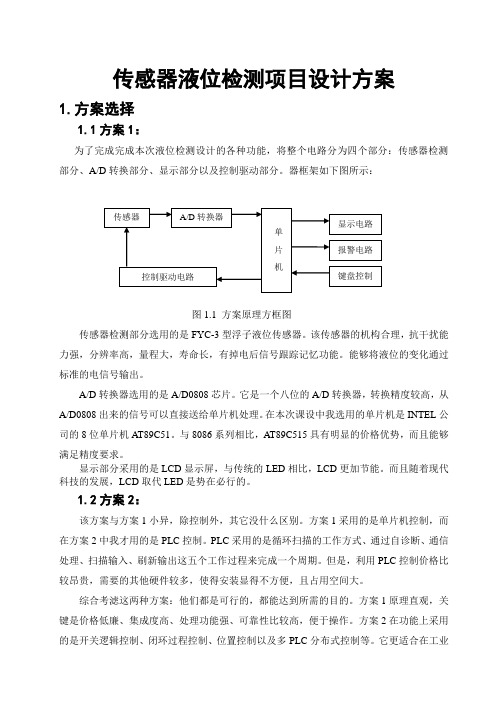
User’s GuideSubmersible Level TransmitterTABLE OF CONTENTS1. Introduction1.1 Product overview1.2 Using this Guide2. Features3. Installation and Maintenance3.1 Wiring3.2 Anchoring3.3 Submersion3.4 Water Intrusion3.5 Cable Care3.6 Position Sensitivity3.7 Sensing Diaphragm4. Troubleshooting & Return Information5. Warranty1. Introduction1.1 Product OverviewThe following User’s Guide is for use with Blue Ribbon Birdcage BC001 along with models 313L, 313S,1103 and any of the other submersible transmitters available.1.2 Using this GuideThis manual is intended to help the end user install, maintain, and provide general service of all Blue Ribbon Submersible Level Transducers.The user should have a general understanding of current loops & general instrument control. All Blue Ribbon Submersible Level Transducers are precision instruments and should be given the same care as any other precision instrument duringinstallation and operation.2. FeaturesAvailable ranges of 0-20” WC thru 300 PSI316L Stainless Steel housing rated to 900 FTWCUp to +-0.10% FSO accuracyChemical resistant Hytrel cableVented cable with Hydrophobic filterLightning surge suppression4-20mA, 0-5Vdc, and 0-10Vdc output3. Installation and Maintenance3.1 WiringConsult wiring listed under Electrical Connections on the Calibration Recordprovided with each serialized individual unit. Do not run wires next to power lines, electrical systems, motors, generators, or any other equipment which may generatea significant amount of electrical noise or magnetic fields.A 4-20mA transmitter requires a DC power supply (typically 9-32 VDC)and mA meter wired in a current loop. Connect the red wire of thetransducer to the + terminal of the power supply and the black wire of the transducer to the + input terminal of the meter. Connect the – input terminal of the meter to the – terminal of the power supply.A VDC transducer requires a DC power supply (9-32 VDC) and voltmeter.Connect the Red wire from the transducer to + on the power supply, the green wire to the +signal of the VDC meter and the Black wire from the transducer to both the –Power on the power supply and –signal on the VDC meter.A mV/V transducer requires a regulated 5-15 VDC power supply andvoltmeter.Connect the Red wire from the transducer to + on the power supply, the green wire to the +signal of the VDC meter the Black wire from thetransducer to the –Power on the power supply and white wire to –signal on the VDC meter.See the wiring guide below3.2 AnchoringIt is recommended that submersible transmitters be installed in a stilling well or attached to rigid conduit using the integrated conduit fitting to prevent possible damage to the transmitter from impact with immovable objects.Some applications require the transmitter to be suspended without a protective stilling well or conduit attachment. In all installations, care should be taken to prevent damage to the submersible cable. Do not secure transmitter tosubmerged objects such as a pump that will caused difficulty with transmitter removal.3.3S ubmersionBlue Ribbon submersible transmitters come standard with Hytrel jacketed cable to minimize the risk of damage from cuts or abrasions.Use care when lowering the transmitter into the well making sure the cable does not drag over sharp edges. Avoid dropping the transmitter from the surface.Damage to submersible cable can lead to failure of the transmitter.3.4 Water IntrusionAlthough Blue Ribbon employs an integrated hydrophobic filter to minimizewater intrusion to the vent tube, care should be taken when terminating the device in a dry, safe location to avoid possible water damage.3.5 Cable CareThe Hytrel cable can support the full weight of the transmitter. Do not bend the cable more than the suggested bend radius of 2” to ensure the vent tube does not crimp. This can obstruct the vent tube to atmospheric pressure causingimproper functionality.If using a junction box care must be taken that the fitting is not over tightened causing damage to the cable and or crimping to the vent tube.3.6 Position SensitivityThe transmitter should be installed in a vertical position otherwise it may read an offset. If the transmitter must be installed in a position other than vertical,measure the output with no pressure applied prior to connection to your display, PLC, or controller Using the value for your zero reading.3.7 Sensing DiaphragmRefrain from pushing, indenting, or probing the pressure port or diaphragm seal.This will likely cause permanent damage to the unit and will not be coveredunder warranty.3. Troubleshooting and Return informationVerify power supply voltage meets transducer requirementsCheck wiring connections and inspect cable for possible damageEnsure the pressure port/diaphragm is not obstructedVerify output load is not shortedIf the problem persists, please call the factory or email Contact:************************** for assistance. Please have the following informationready:Serial numberModel numberRepairs should only be done by Blue Ribbon Corp. Repairs done by customer will void any warranties and may cause permanent damage to unit. Repairs done by customer on Intrinsically Safe units will void the approvals and are a potential explosion hazard.Returned products that have been exposed to hazardous substances should becleaned prior to return and should include the Material Safety Data Sheet for allsubstances.4. WarrantyBlue Ribbon Corp warranties its products to the original customer/purchaser against defects inmaterial and workmanship for a period of one (1) year from the date of delivery by Blue RibbonCorp, as shown in its shipping documents, subject to the following terms and conditions:Without charge Blue Ribbon Corp will repair or replace products found to be defective in materials or workmanship within the warranty period provided that:1. The product has not been subjected to abuse, neglect, accident, incorrect wiring (notprovided by Blue Ribbon Corp), improper installation or servicing, or use in violation ofinstructions furnished by Blue Ribbon Corp.2. As to any prior defect in materials or workmanship covered by this warranty, the product hasnot been repaired or altered by anyone except Blue Ribbon Corp or its authorized serviceagencies.3. The serial number has not been removed, defaced or otherwise changed.4. Examination discloses, in the judgment of Blue Ribbon Corp, a defect in materials orworkmanship which developed under normal installation, use and service.5. Blue Ribbon Corp is notified in advance of, and approves, the return by issuing a ReturnMaterial Authorization Number; and the products are returned to Blue Ribbon Corptransportation prepaid. Products returned without an RMA number will not be accepted andbe returned to sender at sender’s expense.THIS WARRANTY IS THE ONLY WARRANTY AND IS IN LIEU OF ANY OTHER WARRANTY EXPRESSED OR IMPLIED, INCLUDING ANY WARRANTY OR MERCHANTABILITY OR FITNESS. NO REPRESENTATIVE OR PERSONS ARE AUTHORIZED TO GIVE ANY OTHER WARRANTY OR TO ASSUME FOR BLUE RIBBON CORP ANY OTHER LIABILITY IN CONNECTION WITH THE SALE OF ITS PRODUCTS. BLUE RIBBON CORP DOES NOT ASSUME THE COSTS OF REMOVAL AND/OR INSTALLATION OF THE PRODUCT OR ANY OTHER WORKMANSHIP, OR WILL BLUE RIBBON CORP BE LIABLE FOR ANY CONSEQUENTIAL DAMAGES RESULTING FROM THE USE OR INSALLATION OF ITS PRODUCT.Contact our website https:// for a copy of our repair policy or call our repair dept.Copyright© 2008 Blue Ribbon Corp。


《水工艺仪表与控制》课程实验指导书实验准备液位传感器的校准一、实验目的1.了解实验装置的结构和组成。
2.了解信号的传输方式和路径。
3.掌握实验装置的基本操作。
4.掌握液位传感器的校准方法。
二、实验设备1. THBDC-1型控制理论·计算机控制技术实验台平台(含交/直流数字电压表)2. THBXD数据采集卡一块(含37芯通信线、16芯排线和USB电缆线各1根)3. PC机1台(含软件“THBDC-1”)4. THBDY-1单容水箱液位控制系统三、实验原理水箱液位定值控制系统一般有由电流传感器构成大电流反馈环。
在高精度液位控制系统中,电流反馈是必不可少的重要环节。
这里为了方便测量与观察反馈信号,通常把电流反馈信号转化为电压信号:反馈端输出端串接一个250Ω的高精度电阻。
本实验电压与液位的关系为:H液位=(V反馈-1)×12.5 单位:mm水箱液位传感器测量范围:0~10Kp上;24VDC电源供电,4~20mA电流输出,两线制接法。
四、实验步骤1、实验接线1.1 将水箱面板上的“LT –”与实验台的“GND”相连接;水箱面板上的“LT +”与实验台的“AD1”相连接。
1.2将水箱面板上的“输入–”与实验台的“GND”相连接;水箱面板上的“输入+”与实验台的“DA1”相连接。
1.3将水箱面板上的“输出–”与“水泵电源–”连接;水箱面板上的“输出+”与“水泵电源+”连接。
1.4熟悉实验台,按上述步骤连接好实验电路,待检查电路接线无误后,启动实验平台左侧的空气开关和实验台上的电源总开关。
并将+24V、±5V、±15V直流稳压电源的钮子开关拔到“开”的位置。
2、压力变送器调零本实验在开始实验前必须对压力变送器调零操作。
具体方法为:2.1检查储水箱水位是否达到总高度的50%以上,如不够,灌水;2.2打开至水箱的阀门,打开出水阀排空水箱中的水后,关闭出水阀。
2.3零位(零点)校准:旋开压力变送器的后盖,用小一字螺丝刀调节压力变送器中电路板上有“Z”标识的调零电位器,让压力变送器的输出电压为1.00V(对应水箱液位0mm),用交/直流数字电压表“直流”、“20V”电压档测量水箱面板上的水箱液位的电压值;2.4增益(量程)校准:向水箱中打水,并观察水箱液位与压力变送器输出电压的对应情况,其对应关系为:H液位=(V反馈-1)×12.5(当液位为10cm时,输出电压应为1.80V左右),如不对应,再重复步骤2.1、2.2直到对应为止;2.4 如果步骤1)、2)、3)还不能调好水箱液位与压力变送器输出电压的对应情况,那么可适度调节压力变送器中电路板上有“S”标识的增益电位器,再重复步骤2.1、2.2、2.3直到对应为至。


XX有限责任公司【基坑地下水位监测】作业指导书文件版号:副本控制:(不)受控类编写人:编号:审核人:分发号:批准人:持有人:修改记录利用水位监测系统(水位计、水位孔)定期量测水位监测孔的水位埋深,掌握各水位孔地下水位随时间变化的量值及变化速度,从而达到以下目的:1)检验坑内降水施工的实际效果;2)检验坑内降水对坑外地下水位的影响范围和程度;3)检验基坑止水帷幕的止水、隔水效果,避免施工对周围环境造成影响。
2.编制依据(1) 《工程测量规范》GB50026-2007(2) 《建筑变形测量规范》JGJ8-2007(3) 《岩土工程勘察规范》DGJ08-37-2002(4) 《建筑基坑支护技术规程》JGJ120-1999(5) 《国家一、二等水准测量规范》GB12897-2006(6) 《建筑基坑工程监测技术规范》GB50497-20093.适用范围坑内地下水位(疏干降水和降低承压水头)监测、坑外地下水位(潜水、微承水和承压水)监测。
4.基坑地下水位监测4.1仪器设备4.1.1水位管:水位管一般由PVC 工程塑料制成,包括实管、滤水管和束节及封盖。
1)实管管径50mm~70mm,滤水管尺寸与实管相同;2)滤水管管身打有6 列~8 列直径为6mm 左右的滤水孔,纵向孔距50m~100mm。
相邻两列的孔交错排列,呈梅花状布置,便于土中水流入管内;3)滤水管埋设时应在滤孔外包上土工布,起到滤层的作用;4)束节套于两节主管的接头处,起着连接、固定作用;5)承压水水位管也可采用铁质管材,接口采用焊接方式,滤水管外包网布。
4.1.2水位计:公司使用水位计(分辨率:2mm)。
水位计1)测头:由金属车制而成,内部安装了水阻接触点,当触点接触到水面时,便会接通接受系统,当触点离开水面时,就会自动关闭接受系统;2)电缆:由钢尺和导线采用塑胶工艺合二为一,水位计电缆刻度及数值由激光标注,标注数值单位为厘米,每个数字同时代表2mm 刻度;3)接收系统:由音响器和LED 指示灯组成,音响器由蜂鸣器发出连续不断的蜂鸣声响或LED 指示灯发光,两者可通过拨动开关来选用,不管用何种接受系统,测度精度是一致的;4)绕线盘部分:由绕线圆盘和支架组成,绕线圆盘由铁皮冲压制成,支架由钢管制成。

BPRESSURE TRANSDUCERSSubmerSible PreSSure TranSducerSfor level, dePTh or Ground waTer meaSuremenTSe c o n o m i c a l P r i c e h i gh P e r f o r m a n c e PXM709GW availablewith optional lightning protection shownsmaller than actual size.Desiccant, shown smallerB-3BPRESSURE TRANSDUCERSSubmerSible PreSSure TranSmiTTerPXm709Gw SerieS wiTh 4 To 20 ma ouTPuT4 to 20 mA SPECIFICATIONSOutput: 4 to 20 mASupply Voltage: 10 to 30 Vdc [10 to 20 Vdc above 105°C (229°F)] maximum loop res Ω = (Vs-10) x 50Lightning Protection: See application note/manualSee Common Specifications for other parameters.OPTIONS FOR SUBMERSIBLE TRANSDUCERSPX709-BOX1Terminal enclosure without surge protection - for use with all modelsPX709-BOX2Terminal enclosure with surge protection - for use with 4 to 20 mA without Shunt Cal (one surgeprotection module)PX709-BOX3Terminal enclosure with surge protection - for use with voltage output sensors and 4 to 20 mA withShunt Cal option (two surge protection modules)A019385Replacement desiccant to keep moisture out ofvent tubeTo Order4 to 20 m OUTPUT, 0.2% ACCURACY 1 WITH 3 m (10') CABLE (MAX CABLE LENGTH 91 m (300')]GAGE PRESSURE RANGES (INTERMEDIATE RANGES AVAILABLE, CONSULT PRESSURE ENGINEERING)RANGE BAREQUIVALENT DEPTH mH 2OSTANDARD CABLE LENGTHSTANDARD PART NUMBER 2 STANDARD 0.20% ACCURACYLIGHTNING 3 PROTECTED MODELS STANDARD 0.20% ACCURACY0 to 25 mbar 0.25 3 m (10')PXM709GW-025HGI-[**]PXM709LGW-025HGI-[**]0 to 70 mbar 0.7 3 m (10')PXM709GW-070HGI-[**]PXM709LGW-070HGI-[**]0 to 170 mbar 1.7 3 m (10')PXM709GW-170HGI-[**]PXM709LGW-170HGI-[**]0 to 350 mbar 3.6 3 m (10')PXM709GW-350HGI-[**]PXM709LGW-350HGI-[**]0 to 700 mbar7.1 3 m (10')PXM709GW-700HGI-[**]PXM709LGW-700HGI-[**]0 to 110 3 m (10')PXM709GW-001BGI-[**]PXM709LGW-001BGI-[**]0 to 220 3 m (10')PXM709GW-002BGI-[**]PXM709LGW-002BGI-[**]0 to 3.535 3 m (10')PXM709GW-3.5BGI-[**]PXM709LGW-3.5BGI-[**]0 to 771 3 m (10')PXM709GW-007BGI-[**]PXM709LGW-007BGI-[**]0 to 10102 3 m (10')PXM709GW-010BGI-[**]PXM709LGW-010BGI-[**]0 to 17.5178 3 m (10')PXM709GW-17.5BGI-[**]PXM709LGW-17.5BGI-[**]0 to 35357 3 m (10')PXM709GW-035BGI-[**]PXM709LGW-035BGI-[**]0 to 50510 3 m (10')PXM709GW-050BGI-[**]PXM709LGW-050BGI-[**]0 to 707143 m (10')PXM709GW-070BGI-[**]PXM709LGW-070BGI-[**] SEALED GAGE PRESSURE0 to 771 3 m (10')PXM709GW-007BSGI-[**]PXM709LGW-007BSGI-[**]0 to 101023 m (10')PXM709GW-010BSGI-[**]PXM709LGW-010BSGI-[**]0 to 17.5178 3 m (10')PXM709GW-17.5BSGI-[**]PXM709LGW-17.5BSGI-[**]0 to 35357 3 m (10')PXM709GW-035BSGI-[**]PXM709LGW-035BSGI-[**]0 to 50510 3 m (10')PXM709GW-050BSGI-[**]PXM709LGW-050BSGI-[**]0 to 70714 3 m (10')PXM709GW-070BSGI-[**]PXM709LGW-070BSGI-[**] ABSOLUTE PRESSURE 0 to 350 mbar 3.6 3 m (10')PXM709GW-350HAI-[**]PXM709LGW-350HAI-[**]0 to 700 mbar7.1 3 m (10')PXM709GW-700HAI-[**]PXM709LGW-700HAI-[**]0 to 110 3 m (10')PXM709GW-001BAI-[**]PXM709LGW-001BAI-[**]0 to 220 3 m (10')PXM709GW-002BAI-[**]PXM709LGW-002BAI-[**]0 to 3.535 3 m (10')PXM709GW-3.5BAI-[**]PXM709LGW-3.5BAI-[**]0 to 771 3 m (10')PXM709GW-007BAI-[**]PXM709LGW-007BAI-[**]0 to 10102 3 m (10')PXM709GW-010BAI-[**]PXM709LGW-010BAI-[**]0 to 17.5178 3 m (10')PXM709GW-17.5BAI-[**]PXM709LGW-17.5BAI-[**]0 to 35357 3 m (10')PXM709GW-035BAI-[**]PXM709LGW-035BAI-[**]0 to 50510 3 m (10')PXM709GW-050BAI-[**]PXM709LGW-050BAI-[**]0 to 707143 m (10')PXM709GW-070BAI-[**]PXM709LGW-070BAI-[**]Submersible Level TransducerComes complete with 5-point NIST traceable calibration certificate.[**] To order with addition cable length, specify total length in meters, PXM709GW-001BGI-12M , additional cost for length over 3 meters.Consult sales for stock cable length to assure fast delivery.1.) To order with optional high accuracy for extra cost, insert code “-HH” after “I” for 0.08% accuracy, PXM709-010BGI-HH-[**].2.) To order with ½ NPT Conduit fitting for extra cost, specifiy Model PXM709C , PXM709CGW-170HGI.3.) To order with optional Lightning/Surge protection for extra cost, specify Model PXM709LGW, i.e. PXM709LGW-001BGI.4.) To order with optional Lightning/Surge protection and conduit fitting for extra cost, specify Model PXM709CLGW, i.e. PXM709CLGW-001BGI.Ordering Examples: PXM709GW-350HGI, 350 mbar gage submersible transducer with 4 to 20 mA output, 3 m (10') of cable and standard 0.2% accuracy.PXM709LGW-001BAI-HH-7.5M, 1 bar absolute pressure, lightning protected submersible transducer with 4 to 20 mA output, 7.5 m (25') of cable and high 0.08% accuracy.PXM709CGW-700HGI-6M , 700 mbar gage submersible transducer with 4 to 20 mA output, a ½ NPT conduit fitting and 6 m (20') of cable with 0.2% accuracy.B-4f a s t d e l i v er y –h ig h l i g h t ed T y p i c a ll yS t o c k t o 2w e e k s !Optional Higher Accuracy: Add suffix “-HH” after the “V” or “I” in the model number.Optional Conduit Fitting Cable Exit: Specify model PXM709CGW.Optional Lightning Protection: Specify model PXM709LGW.Optional Lightning protection and conduit fitting: Specify model PXM709CLGW.OMEGA ® has designed the PX709 Series to be highly modular so we can configure and ship most models in 1 week. We stock the modules and can quicklyassemble and do precision calibrations for any of our several thousand possible combinations. The cable molded onto the transducer using a high pressure, temperature molding process to assure completesealing. We stock a series of molded cable assemblies in standard lengths to suit most common applications which we can build onto your transducer and deliver in 1 week (see the list below). We also can provide custom lengths with slightly longer lead times to allow for the molding process.STandard cable lenGThS for faST deliverYwaTerProof Terminal boXSTANDARD LENGTHS4.5 m (15')7.5 m (25')12 m (40')15 m (50')18 m (60')20 m (65')22.5 m (74')30 m (100')45 m (150')PX709C with ½ NPT conduit fitting.PX709 with standard cable fitting.PX709-BOX1 waterproof terminal box for PX709 provides awaterproof environment for electrical terminations and housing the desiccant. Also available with optional lightning protection for downstream instruments.。


传感器验指导书-CAL-FENGHAI.-(YICAI)-Company One1传感器与检测技术实验指导书张秀峰大连民族学院机电信息工程学院2014年10月20日实验基本要求1. 每位学生必须按规定完成实验课,因故不能参加实验者,应课前向指导教师请假(必须经有关领导批准)。
对所缺实验要在期末考试规定时间内补齐,缺实验者不得参加期末考试。
2.每次实验课前,必须作到预习,弄清实验题目、目的、内容、步骤和操作过程,及需记录的参数等,认真做好预习报告。
在实验前,指导教师要检查预习结果并接受进行提问。
对不写预习报告,又回答不出问题者,不准做实验。
3.每次实验课前,学生须提前5分钟进入实验室,找好坐位,检查所需实验设备,做好实验前的准备工作。
4.做实验前,了解设备的原理和正确使用方法。
在没有弄懂仪器设备的使用方法前,不得贸然使用,否则因使用不当造成仪器设备损坏的,根据大连民族学院《仪器设备损坏丢失处理暂行办法》规定进行处理。
5.实验室内设备在实验过程中不准任意搬动和调换,非本次实验所用仪器设备,未经指导教师允许不得动用。
6.要求每位学生在实验过程中,要具有严谨的学习态度、认真、踏实、一丝不苟的科学作风。
坚持每次实验都要亲自动手,不可“坐车”,实验小组内要轮流接线、操作和记录等工作,无特殊原因,中途不得退出实验,否则本次实验无效。
7.实验中若接线、改接、拆线都必须在切断电源的情况下进行(包括安全电压),线路连接完毕再送电。
实验中,特别是设备刚投入运行时,要随时注意仪器设备的运行情况,如发现有超量程、过热、异味、冒烟、火花等,应立即断电,并请指导老师检查、处理。
8.实验过程中,如出现事故,就马上拉开电源开关,然后找指导教师和实验技术人员,如实反映事故情况,并分析原因和处理事故。
如有损坏仪表和设备时,应马上提出,按有关规定处理。
9.每次实验结束,指导教师要对实验数据和结果进行,要经检查并签字,在教师确认正确无误后,学生方可拆线。


***公司测量专业作业指导书地下水位监测实施细则文件编号:版本号:分发号:编制:批准:生效日期:地下水位监测实施细则1.目的为使测试人员在做检测时有章可循,并使其操作合乎规范。
2.适用范围适用于地下水位监测。
3.检测内容通过在受力面埋设钢尺水位计,对基坑地下水位变化进行量测。
4.检测依据《建筑基坑工程监测技术规范》(GB50497—2009)。
5.主要仪器设备5.1 频率读数仪;5.2钢尺水位计:地下水位量测精度不宜低于10mm。
6. 检测条件6.1 气温应在-10℃~+40℃;6.2 相对湿度≤80%。
7. 检测前的准备7.1 检测仪器和计量器具必须满足精度、等级要求,并应有计量部门定期检验的合格证书;7.2测试工作前应通过搜集资料和现场踏勘后编制测试纲要;7.3搜集资料应包括有关的工程设计施工场地周围环境和地质资料并应根据测试任务书要求认真进行分析研究;7.4现场踏勘应着重调查了解场地环境和埋设作业条件;7.5测试纲要内容应包括目的与要求工程概况工作量布置及依据仪器类型选定和精度要求埋设和测试方法监测工程要求的控制标准当日阶段和最终提交的成果;7.6监测传感器埋设前应进行性能检验和编号;7.7监测传感器宜在基坑开挖前至少1 周埋设,并取开挖前连续2d 获得的稳定测试数据的平均值作为初始值。
8.钢尺水位计埋设8.1潜水水位管应在基坑施工前埋设,滤管长度应满足量测要求;承压水位监测时被测含水层与其他含水层之间应采取有效的隔水措施。
9.试验步骤9.1测量时,拧松绕线盘后面的止紧螺丝,让绕线盘自由转动后,按下电源按钮(电源指示灯亮),把测头放入水位管内,手拿钢尺电缆,让测头缓慢地向下移动,当测头的触点接触到水面时,接收系统的音响器便会发出连续不断的蜂鸣声,此时读写出钢尺电缆在管口处的深处的深度尺寸,即为地下水位离管口的距离。
9.2若是在噪声比较大的环境中测量时,蜂鸣声听不见,可改用峰值指示,只要把仪器面板上的选择开关拨至电压挡即可,测量方法同上,此时的测时精度与音响测得的精度相同。

超声波液位计检修作业指导书编制:审核:批准:XX年XX月XX日发布目录一、设备描述 (3)1. 设备概述 (3)2. 设备基本工作原理、现场条件和安装原理 (3)二、检修准备 (4)1.作业人员资格及类别 (4)2.工器具及测量用具 (4)3.备品备件 (4)4.检修所需参考图纸资料 (5)三、作业风险危害识别及安全措施: (5)四、检修过程及步骤: (5)五、验收标准 (7)1.日常维护验收标准 (7)2.检修验收标准 (7)六、维护保养事项 (8)七、常见故障处理 (8)一、设备描述1.设备概述超声波液位计是由微处理器控制的数字液位仪表,由超声波换能器、处理单元、输出单元三部分组成。
在测量中超声波脉冲由传感器(换能器)发出,声波经液体表面反射后被同一传感器接收或超声波接收器,通过压电晶体或磁致伸缩器件转换成电信号,并由声波的发射和接收之间的时间来计算传感器到被测液体表面的距离。
由于采用非接触的测量,被测介质几乎不受限制,可广泛用于各种液体和固体物料高度的测量。
2.设备基本工作原理、现场条件和安装原理2.1、超声波液位计的工作原理超声波物位计工作原理是由超声波换能器(探头)发出高频脉冲声波遇到被测物位(物料)表面被反射折回反射回波被换能器接收转换成电信号.声波的传播时间与声波的发出到物体表面的距离成正比.声波传输距离S与声速C和声传输时间T的关系可用公式表示:S=C×T/2.由于发射的超声波脉冲有一定的宽度,使得距离换能器较近的小段区域内的反射波与发射波重迭,无法识别,不能测量其距离值。
这个区域称为测量盲区。
盲区的大小与超声波物位计的型号有关。
探头部分发射出超声波,然后被液面反射,探头部分再接收,探头到液(物)面的距离和超声波经过的时间成比例:距离 [m] = 时间×声速/2 [m]声速的温度补偿公式:环境声速= 331.5 + 0.6×温度2.2超声波液位计的现场条件:在下面的任何一种情况,要注意:2.2.1有泡沫的液体/固体2.2.2周围有强电压,强电流,强电磁干扰,尽量避免高电压,高电流及强电磁干扰2.2.3大风和太阳直晒2.2.4强震动超声波液位计是由微处理器控制的数字物位仪表。

LEVEL SENSORS & SWITCHESLevel Sensors are used in a wide variety of industries and applications. usually, the aim is to avoid overfill that would cause potentially hazardous situations, so accuracy and reliability are of paramount importance. Our level sensors are designed, tested and manufactured to the highest standards and trusted by our customers to measure and mitigate risk in applications as diverse as blood dialysis treatment, storage and transport of volatile fuel and food-safe vending machines.A float switch is a type of level sensor, a device most commonly used to detect the level of liquid within a tank or other receptacle. A float switch is one of the most simple, reliable and well proven technologies for liquid level sensing and is available in many different types and configurations, each suited to different applications. For example, a float switch may beused as an alarm, as an indicator, to control a pump or to provide a signal to another device. Like other switch types, float switches can be electrically either Normally Open (NO) or Normally Closed (NC). They can also be configured to have either single or multiple switching points. For applications requiring a repeatable signal indicating that fluid has reached a predetermined level, the float switch is often an excellent solution. Take for example a tank containing a fluid that must be maintained between a minimum and maximum level. When the fluid level reaches the minimum level, a float switch can be used to signal a pump to operate and replenish the tank. When the fluid reaches the maximum level, a float switch can be used to signal the pump to stop working. In this way, the fluid in the tank remains within the required level range.This is a very simple example and it should be noted that float switches can be specified to provide significantly more complex level control options. However, if the sensor is required to do more than simply initiate an action at a specific level (or levels), then a float switch (or any point level technology) may no longer be the best solution and then an hydrostatic sensor level is preferred since cansupply the value of the level at any position through an analog output signal.Our wide range oftechnologies and materials allow us to offer solutions for the most demanding applications|APPLICATIONS| CONSIDERATIONS FOR PRODUCT SELECTIONApplications for level switches and sensors are basically divided in 2 types: as a single or dual point level (maximum or minimum or both) and as a continuous level control to monitor and control the system based on the actual level value at any time. In the first case in which switches have to be used, there are relatively; those are relatively cost effective solutions that prevent dangerous situations like pump , like a pump running dry, loss of dangerous or valuable fluids, overspill, loss of service and downtime. In a case where continuous levels need to be controlled, level sensors like the hydrostatic can be used. Both situations can be found in the most typical applications for these products, which are endless. Below is a list of the most common markets and application examples. When considering what type of float switch to employ, it is vital to understand the application in which the switch is to be introduced. Important factors are:• Medical (Dialysis, bedpan washer)• Ink jet printers (Ink/solvent reservoir, colour reservoir)• Vending (hot water level, cold water level)• Transportation (Auto coach toilets)• Professional kitchen equipment (refrigerators, nebulisers)• Industrial dishwasher (water level)• Food and beverage •Water storage tanks• The fluid level state (or states) that require a signal from the float switch• Electrical load to be switched: voltage, current, power, resistive, capacitive or inductive• The fluid type (to ensure chemical compatibility). Sensata | Cynergy3 float switches and associated gaskets and seals are available in many materials to give a broad range of suitability • Working temperature and pressure• Mounting type: horizontal or vertical, external or internal. Space available within the tank • Cable and connection: flying lead or connector, cable length and type • Approvals required: WRAS, ATEX, UL, NSF, etc • Likelihood of deposit build up• Level sensor and float switch solutions for all types of liquid including foaming liquids and those containing particles or solids • Customizable solutions designed to meet the size, shape, material and industry regulations your application requires • Manufactured and 100% tested to meet the highest quality standards• Made to last with some bespoke products still in service after over 20 years • Wireless Level and Flow Switches availableVertical float switches have a magnet mounted within the float and a reed switch mounted within the body of the unit. The float fits around the stem and it rises and falls with the level ofthe liquid. When the float nears the reed switch, the magneticforce causes the switch to open or close. These switches can bemounted on the top or at the bottom of a container, making them| FLOAT SWITCHESVERTICAL SeriesSwitch Material Mount ActionThe horizontal / side mounting type switches normally has a fixed housing, passing through the sidewall of the tank and includes a hinged float attached to the housing. As with a vertical switch, the float rises and falls with the levels of the liquid. When the float nears the reed switch, it moves a magnet close to the switchand opens or closes the circuit. Horizontal Liquid Level Switches are side-mounted through a hermetically sealed hole on the sideof a tank.FloatReed Switch Offered in a wide range of materials, PPS, Polypropylene, Nylon, PVDF and stainless steel to suit almost all fluids and temperatures within food, chemical processing, oil & gas, marine and nuclear facilities. A float switch needs to be constructed from the right materials, ones which are compatible with the liquids and temperatures of the particular application. Component damage as a result of incorrect materials selection can ultimately cause failure of a float switch, which may have severe consequences. Typical float switch materials include:• Nylon: suitable for many oils, diesel, organic chemicals and MEK-based printing inks.• P olypropylene (P P ): suitable for many acids and alkali, detergents, inorganic and organic chemicals, oils and water.• P olyphenylene sulphide (P P S): suitable for many of the more aggressive chemicals and higher process temperatures, up to 120°C.• Buna: suitable for many oils, diesel, petrol and water (non-potable applications).• Stainless steel: suitable for most medical and food applications, chemicals, hydraulic fluids, fuel oils andapplications with process temperatures up to 135°C. Selection of the most suitable materials for both float switch and gasket can be made by referring to a ‘Chemical Compatibility’ table. For some process liquids, it may be necessary to obtain a sample float switch to test the compatibility.FLOW SWITCH MATERIALS| FLOAT SWITCHESHORIZONTAL| OPTICAL LEVEL SENSORSThese submersible float switches, used mainly for sewer and industrial waste systems, are cable mounted and can have a normally open or normally closed configuration. These self-weighted cable end float switches are designed for use in turbulent industrial fluids and fluids with suspended agglomerates, such as sewer water. Version with Polyurethane cable are for use in fuel oils. The switch are water resistant up to a depth of 100m, and is insensitive to humidity and condensation, due to the particular design of the switch element. This makes it suitable for applications where there may be wide or rapid fluctuations in ambient or fluid temperatures. Switching capacity of these design is 10A or 20A.An optical liquid level sensor uses an infra-red LED and phototran-sistor accurately positioned at the base of the sensor’s tip. When the tip is air, infra-red light reflects internally round the tip to the phototransistor providing good optical coupling between the two. When the sensor’s tip, is immersed in liquid, the infra-red light escapes from the tip causing a change in the amount of light atthe photo-transistor, which makes the output change state.| CABLE END LEVEL SWITCHESSensor tipSensor tipHydrostatic level sensors are robust packages for sensing in various liquid including water, oil and non-aggressive chemicals. Sensata’s portfolio features both external mount and submersible and is suited for a range of applications from measuring liquid level in small tanks to large tanks, rivers and reservoirs. Depending on the application pressure and accuracy requirements, piezo-resistive media-isolated silicon sensing with stainless steel diaphragm or ceramic sense elements are used. Sensata’s hydrostatic level pressure sensors incorporate a ceramic or MEMs sensing element with the latest state of the art electronics in an IP68 stainless steel housing. Accurate and highly reliable Sensata’s hydrostatic level pressure sensors are ideal formeasuring a broad range of liquids and most hydrocarbon based| HYDROSTATIC LEVEL SENSORS| CONTROL MODULES & ACCESSORIESThe operating environment is critical to the choice of float switch. A water tank for an industrial process may only require a simple plastic float switch. However, if the application is in a hazardous area - a petrochemical storage tank where flammable gases, va-pours or dust are present, for example - a stainless steel, explo-sion-proof float switch will be required.Over the years, Sensata has custom engineered many variants of its float switches to match particular customer requirements in a wide range of industry sectors, including oil, gas and petro-chemicals: food and beverage: chemicals and pharmaceuticals; water and wastewater; and process manufacturing. These solu-tions have been for all types of environment, including industrial process control, safe areas, intrinsically safe and hazardous areas (ATEX-certified), as well as WRAS-approved switches for drinking water applications.|CUSTOM ENGINEERED SOLUTIONSSensor SensorCONTACT US+44 (0)1202 897969*********************Cynergy3 Components Ltd.7 Cobham Road,Ferndown Industrial Estate,Wimborne, Dorset,BH21 7PE, United KingdomABOUT USSensata Technologies is one of the world’s leading suppliers of sensing, electrical protection, control and power management solutions with operations and business centers in twelve countries. Sensata’s products improve safety, efficiency and comfort for millions of people every day in automotive, appliance, aircraft, industrial, military, heavy vehicle, heating, air-conditioning and ventilation, data, telecommunications, recreational vehicles and marine applications. F or more information please visit Sensata’s websiteCopyright © 2021 Sensata Technologies, Inc.09/2021。