无线工程师操作手册--华为--FDD、NB网络优化概述
- 格式:pptx
- 大小:5.75 MB
- 文档页数:14
通信网络优化技术手册第1章通信网络优化基础 (3)1.1 网络优化概念与目标 (3)1.2 网络优化方法与分类 (4)1.3 网络优化流程与实施 (4)第2章网络功能评估指标 (4)2.1 传输功能指标 (4)2.2 覆盖功能指标 (5)2.3 容量功能指标 (5)2.4 网络质量指标 (5)第3章无线网络优化 (6)3.1 无线信号传播模型 (6)3.2 无线覆盖优化 (6)3.3 无线接入优化 (6)3.4 无线网络干扰优化 (7)第4章传输网络优化 (7)4.1 传输网络架构与规划 (7)4.1.1 传输网络架构 (7)4.1.2 传输网络规划 (8)4.2 传输链路优化 (8)4.2.1 链路冗余设计 (8)4.2.2 链路负载均衡 (8)4.2.3 链路故障检测与修复 (8)4.3 传输设备功能优化 (8)4.3.1 设备选型与升级 (8)4.3.2 设备配置优化 (8)4.3.3 设备散热与节能 (9)4.4 传输网络保护与恢复 (9)4.4.1 网络保护技术 (9)4.4.2 网络恢复技术 (9)4.4.3 网络保护与恢复的协同 (9)第5章网络规划与设计优化 (9)5.1 网络规划方法与工具 (9)5.1.1 网络规划概述 (9)5.1.2 网络规划方法 (9)5.1.3 网络规划工具 (9)5.2 网络设计原则与优化策略 (10)5.2.1 网络设计原则 (10)5.2.2 网络优化策略 (10)5.3 网络规划中的容量与覆盖优化 (10)5.3.1 容量优化 (10)5.3.2 覆盖优化 (10)5.4 网络规划中的投资与成本控制 (10)5.4.1 投资估算 (10)5.4.2 成本控制策略 (11)第6章网络设备优化 (11)6.1 设备选型与配置优化 (11)6.1.1 设备选型原则 (11)6.1.2 设备配置优化 (11)6.2 设备功能监控与优化 (11)6.2.1 功能监控方法 (11)6.2.2 功能优化策略 (11)6.3 设备能耗优化 (11)6.3.1 能耗分析与评估 (11)6.3.2 能耗优化措施 (11)6.4 设备维护与升级策略 (12)6.4.1 设备维护策略 (12)6.4.2 设备升级策略 (12)6.4.3 设备生命周期管理 (12)第7章网络协议优化 (12)7.1 网络协议功能分析 (12)7.1.1 网络协议功能指标 (12)7.1.2 功能分析方法 (12)7.1.3 功能优化策略 (12)7.2 TCP/IP协议优化 (12)7.2.1 TCP协议优化 (12)7.2.2 IP协议优化 (12)7.2.3 应用层协议优化 (12)7.3 移动通信网络协议优化 (13)7.3.1 移动通信网络协议功能分析 (13)7.3.2 无线接入网络协议优化 (13)7.3.3 移动性管理协议优化 (13)7.4 网络安全协议优化 (13)7.4.1 安全协议功能分析 (13)7.4.2 加密算法优化 (13)7.4.3 认证与密钥管理优化 (13)第8章网络管理优化 (13)8.1 网络管理策略与体系结构 (13)8.1.1 网络管理策略 (14)8.1.2 网络管理体系结构 (14)8.2 功能管理优化 (14)8.2.1 网络功能监测 (14)8.2.2 功能优化策略 (14)8.3 故障管理优化 (15)8.3.1 故障预防 (15)8.3.2 故障检测与定位 (15)8.3.3 故障恢复 (15)8.4 安全管理优化 (15)8.4.1 安全策略制定 (15)8.4.2 安全防护技术 (15)8.4.3 安全事件处理 (15)第9章网络优化案例分析与实践 (15)9.1 3G网络优化案例分析 (15)9.1.1 案例背景 (15)9.1.2 优化方案 (16)9.1.3 实施效果 (16)9.2 4G网络优化案例分析 (16)9.2.1 案例背景 (16)9.2.2 优化方案 (16)9.2.3 实施效果 (16)9.3 5G网络优化案例分析 (16)9.3.1 案例背景 (16)9.3.2 优化方案 (16)9.3.3 实施效果 (17)9.4 综合网络优化实践 (17)9.4.1 融合不同网络技术 (17)9.4.2 跨区域协同优化 (17)9.4.3 智能化网络优化 (17)9.4.4 持续优化与维护 (17)第10章网络优化技术的发展趋势 (17)10.1 新技术对网络优化的影响 (17)10.2 大数据与网络优化 (17)10.3 云计算与网络优化 (18)10.4 未来网络优化技术的发展方向 (18)第1章通信网络优化基础1.1 网络优化概念与目标通信网络优化是指通过对现有通信网络进行功能分析、问题诊断和参数调整,以提高网络的整体功能和用户体验。
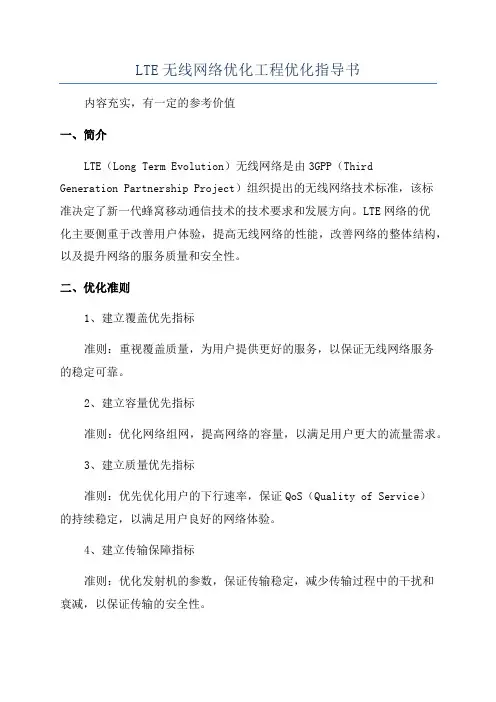
LTE无线网络优化工程优化指导书
内容充实,有一定的参考价值
一、简介
LTE(Long Term Evolution)无线网络是由3GPP(Third
Generation Partnership Project)组织提出的无线网络技术标准,该标
准决定了新一代蜂窝移动通信技术的技术要求和发展方向。
LTE网络的优
化主要侧重于改善用户体验,提高无线网络的性能,改善网络的整体结构,以及提升网络的服务质量和安全性。
二、优化准则
1、建立覆盖优先指标
准则:重视覆盖质量,为用户提供更好的服务,以保证无线网络服务
的稳定可靠。
2、建立容量优先指标
准则:优化网络组网,提高网络的容量,以满足用户更大的流量需求。
3、建立质量优先指标
准则:优先优化用户的下行速率,保证QoS(Quality of Service)
的持续稳定,以满足用户良好的网络体验。
4、建立传输保障指标
准则:优化发射机的参数,保证传输稳定,减少传输过程中的干扰和
衰减,以保证传输的安全性。
三、优化监测工具
1、室外覆盖优先监测工具
主要用于检测室外覆盖,优先监测覆盖质量,包括检测RSSI (Received Signal Strength Indication)、RxLev(Received Level)、IPER(Interference Power)、CINR(Carrier to Interference Noise Ratio)。
2、室内覆盖优先监测工具。
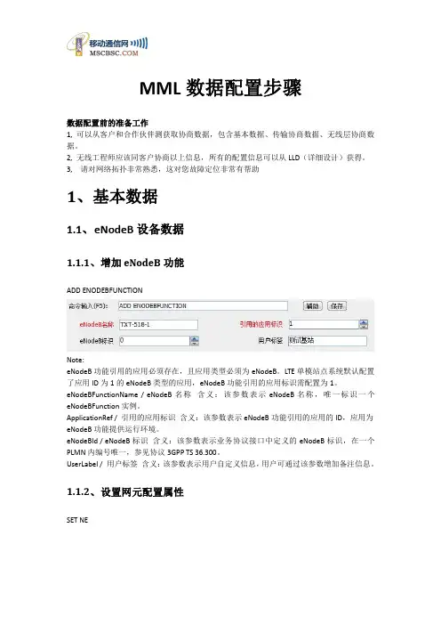
本文部分内容来自网络整理,本司不为其真实性负责,如有异议或侵权请及时联系,本司将立即删除!== 本文为word格式,下载后可方便编辑和修改! ==华为操作指导书篇一:LTE华为后台操作指导书RNC机房操作指导总结一. TD-LTE组网简介整个TD-LTE系统由3部分组成,核心网(EPC),接入网(eNodeB),用户设备(UE).EPC又分为三部分:MME 负责信令处理部分,S-GW 负责本地网络用户数据处理部分 P-GW 负责用户数据包与其他网络的处理。
接入网也称E-UTRAN,由eNodeB构成。
eNodeB与EPC之间的接口称为S1接口,eNodeB之间的接口称为X2接口,eNodeB与UE之间的接口称为Uu接口。
二. LTE网管客户端安装1、 LTE网管系统目前有两套,一套为M201X系统,另一套为新版OMC920系统,两套系统主要功能基本相同,但后者将TDS系统统一整合进来;2、 LTE网管的安装:系统的安装:M201X网管系统的安装,首先在IE地址栏中,输入IP地址http://10.211.176.80/cau/,然后下载安装,OMC920网管系统,则要输入IP地址http://10.212.96.45/cau/,然后下载安装;3、 OMC920系统网管安装成功后,需要将附件hosts文件复制到C:\WINDOWS\system32\drivers\etc目录下,替换系统自带的hosts文件,否则登录时会出现异常,M201X系统没有此类问题;后面操作因M201X与OMC920类似,故仅以OMC920网管系统为例说明;三. LTE网管客户端登录登陆网管OMC920客户端。
打开客户端后,显示的是“用户登陆”,需要填写,用户名,密码,当多个OMC920客户端登陆时,需点击服务器下拉菜单,增加网元信息。
成功登录后进入OMC920网管系统首页,内容包括各类维护操作的菜单栏、工具栏和一些快捷工具图示等;OMC维护系统包括MML命令、结果查询、监控和维护等主要功能,后面对这些具体功能进行详细介绍;四. LTE常用的操作4.1 eNodeB MML常用命令在网络规划和优化工作中,对单个eNodeB进行远端操作维护的情况较少,一般都可以在M201X下对eNodeB进行相关的操作。
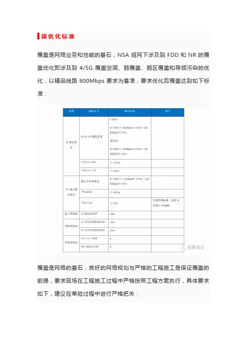
▋簇优化标准覆盖是网络业务和性能的基石,NSA组网下涉及到FDD和NR的覆盖优化即涉及到4/5G覆盖空洞、弱覆盖、越区覆盖和导频污染的优化,以精品线路800Mbps要求为基准,要求优化后覆盖达到如下标准:覆盖是网络的基石,良好的网络规划与严格的工程施工是保证覆盖的前提,要求现场在工程施工过程中严格按照工程方案执行,具体要求如下,建议在单验过程中进行严格把关:1、天馈实施方案:单验过程中,核查天馈实施方案即天线位置、天线挂高、方位角和下倾角与设计院规划是否相符,不符需通知相关人员处理;2、天馈安装位置无阻挡可调整:为保证后续优化的灵活性,要求安装后天馈无阻挡、可自由调整。
▋邻区梳理1、4/5G邻区规划通过4/5G邻区规划与优化,需要保证道路测试场景下SN添加成功率100%,对于切换失败点或者不切换区域需要及时分析,具体4/5G 邻区规划原则如下:1)距离原则(通过站点分布的距离原则需完成90%邻区的规划)步骤1:梳理并核实5G建设区域内的锚点小区工程参数,包含经纬度、方位角、站高等关键数据;步骤2:添加5G站点周边锚点小区(包含4/5G共站邻区)两圈,如果锚点与5G站点1比1建设,则可以直接继承共扇区邻区,即某锚点小区的所有同频4G邻区,均需添加与该锚点小区同扇区的5G小区为4-5G邻区。
基于站点分布的4/5邻区规划可通过“mongoose工具即LTE到NR 的邻区规划工具”进行4/5G邻区规划,相关工具可通过“”网页进行下载(具体操作方法见对应下载链接中的工具说明)。
2)基于现场测试情况进行4/5G邻区添加。
通过现场测试情况,针对漏配邻区进行增补,NR邻区增补后,需要核查对应锚点LTE的邻区关系以及NR对应的锚点关系需要重新梳理,避免NR小区间配置邻区后,对应的锚点无邻区。
3)4/5G邻区漏配判定方法。
上报SN添加请求的MR后网络侧无响应或携带SN切换失败:信令体现为终端不停上报5G测量结果的MR或锚点切换过程中终端上报了5G测量结果,但网络侧无响应,具体如下例(锚点enbid:885119-202未添加5G PCI:463为邻区导致的SN添加失败)。

5G 基站概述及基本操作 Copyright © Huawei Technologies Co., Ltd. All rights reserved.培训目标●学完本课程后,您应该能:☐了解华为5G基站的方案及产品☐了解BTS5900序列基站的功能及模块☐了解LampSite功能及模块☐了解5G基站的基本操作,包括设备及链路管理,基本无线参数管理1.5G基站概述2.5G基站基本操作1.5G基站概述1.1 系统概述1.2 系统结构1.3 机柜及其部件1.4 室内方案概述2. 5G基站基本操作SA(Standalone)组网采用Option 2组网架构,即采用端到端的5G网络架构,从终端、无线新空口到核心网都采用5G相关标准,支持5G各类接口和实现5G各项功能来提供5G各类服务。
●NSA主要聚焦5G初期部署的eMBB业务。
●LTE 是锚点,可以重用当前的EPC,可以快速引入5G。
华为gNodeB基站描述5G当前支持多种站型,包括DBS3900、DBS5900等多种,基站硬件主要由机柜、BBU和射频模块组成。
基带单元BBU3910/BBU5900射频单元RRU/AAU 机柜CPRI/eCPRI容量规格项目规格NR(TDD)-Sub6G(18个小区, 100MHz,2T2R/4T4R/32T32R/64T64R)2块UMPTg+6块UBBPg2d NR(TDD)-Sub6G(36个小区, 100MHz, 2T2R/4T4R/8T8R)2块UMPTe+6块UBBPg3e部署场景AAU RRU站点供电方案BBU 机柜BBU 时钟目录1.5G基站概述1.1 系统概述1.2 系统结构1.3 机柜及其部件1.4 室内方案概述2. 5G基站基本操作BBU5900和BBU3910物理结构●BBU5900●尺寸:86mm x 442mm x 310mm(高x 宽x 深) ●重量:满配置≤18kg ●BBU3910●尺寸:86mm x 442mm x 310mm(高x 宽x 深) ●重量:15kg(满配置)BBU逻辑结构BBU采用模块化设计,由基带子系统、整机子系统、传输子系统、互联子系统、主控子系统、监控子系统和时钟子系统组成BBU5900上有11个槽位,各类型单板在BBU槽位中的分布如下图所示。
Smart Device Simple WorldThank you for choosing HUAWEI Mobile WiFiSupported functions and actual appearance depend on the specific models you purchased. The illustrations are provided for your reference only. For details about the model you selected, consult your service provider.This guide briefly describes the functions of the Mobile WiFi. For details about how to set management parameters, see help on the web management page.Copyright © Huawei Technologies Co., Ltd. 2012. All rights reserved.THIS DOCUMENT IS FOR INFORMATION PURPOSE ONLY, AND DOES NOT CONSTITUTE ANY KIND OF WARRANTIES.12Getting to Know HUAWEI Mobile WiFiConnection ScenariosA Wi-Fi device or computer can be connected to the Internet through the Mobile WiFi. The actual connection procedure depends on the operating system of the Wi-Fi device or computer. The connection scenarios illustrated here are for your reference.Scenario 1: Multi-device access via Wi-Fi Scenario 2: One-device access via USBScenario3: Multi-device access via Wi-Fi and USB at the same timeSmart phoneGame machineDigital cameraLaptop34AppearanceNo. Item 1 Screen2 WPS button3 Power button4 USB port5 microSD card slot6 Battery button7 Strap holeScreenNo. Item1 Signal strength2 Network3 z Wi-Fi enabledz Number of devices connected 4 Internet connection status5 z New messagesz Number of new messages6 Battery level7 International roaming state8 z Traffic dataz Connection duration5Note:z Wi-Fi: Wireless fidelityz WPS: Wi-Fi protected setupz Traffic statistics are for your reference only. To obtain the actual traffic data, contact your service provider.67Before You StartInstalling the SIM Card and the BatteryCaution: Do not use any SIM card that is not standard or is incompatible with the Mobile WiFi. Otherwise, the Mobile WiFi may be damaged.Insert the SIM card in the card slot. Be sure that the SIM card is facing in the right direction,8Installing the microSD Card1. Remove the rubber cap from the microSDcard slot. Then insert the microSD card into the slot.2. After inserting the microSD card completely, attach the rubber cap. Note: z The microSD card is an optional accessory. If a microSD card did not come with yourMobile WiFi, you may purchase one yourself. z To remove the microSD card, press in the card gently. The microSD card will pop outfor removal. z Do not remove the microSD card when it is in use. Doing so may damage the cardand the Mobile WiFi, and data stored on the card may be lost.Charging the BatteryNote: If the battery has not been used for a long time, it must be charged first.9Method 1: Using the charge rCaution:z Only use chargers compatible with the MobileWiFi and provided by a designatedmanufacturer. Use of an incompatiblecharger or one from an unknownmanufacturer may cause the Mobile WiFi tomalfunction, fail, or could even cause a fire. Such use voids all warranties, whether expressed or implied, on the product.z The charger is an optional accessory. If the charger is not provided in the package, you can contact your local dealer to buy one yourself.Method 2: Connecting to a PC for chargingConnect the Mobile WiFi to a PC using acompatible data cable.10Accessing the Internet via Wi-Fi ConnectionNote: By default, management parameters are preset on the Mobile WiFi according to the requirements of the service provider. Follow the steps below to quickly access the Internet. For the details about how to set management parameters, see help on the web management page.Step1: Power on the Mobile WiFiPress and hold POWER until the screen lights up. The Mobile WiFi is powered on.Note: Press and hold POWER to power off the Mobile WiFi.Step2: Establish a Wi-Fi Connection (Take a computer with Windows ® XP operating system as an example)1. Make sure that the Wi-Fi is enabled.112. Select Start > Control Panel > Network Connections > Wireless Network Connection . Note: To set up a Wi-Fi connection, the PC must have a wireless network adapter installed. If Wireless Network Connection is displayed, a wireless network adapter is available. Otherwise, check to make sure you have a wireless network adapter installed.3. Click View available wireless networks to display a list of wireless networks available.4. Select a network indicated by the SSID of the Mobile WiFi, and then click Connect . Note:z If the encryption parameter is already set for the Mobile WiFi, the Wireless NetworkConnection z WiFi.5. Wait until the wireless connection icon is displayed inthe status area in the lower right corner of the PCscreen.Step3: Access the InternetAfter you establish a Wi-Fi connection successfully, you can access the Internet using the following modes.Caution: Please select a proper Internet connection mode based on your service expense. For example, if you are subscribed to the time-based network service, you are recommended to select Manual mode. For details about the service expense, consult your service provider.Mode OperationsAuto After the Mobile WiFi is powered on, it will connect to the Internetautomatically if data transmission is required. If there is no datatransmission over a period of time, the Mobile WiFi automaticallyterminates the Internet connection.Manual Launch the web management page and follow the prompts toconnect to or disconnect from the network.12Note:z Launch the web management page to select the mode for accessing the Internet.z You can choose whether to enable the Mobile WiFi to connect to the Internet automatically even while you are roaming. If this function is disabled, the Mobile WiFi automatically disconnects from the Internet while you are roaming. To access theInternet, set up a connection manually.Accessing the Web Management Page1. Make sure that the connection between the Mobile WiFi and the client is a properone.2. Start the Internet browser and enter http://192.168.1.1 in the address bar.3. Enter the password and log in to the web management page.Note:The default password is admin.13Daily UsePower Saving ModeIf no operation is performed on the Mobile WiFi within a preset period, the screen turns off. Press any key to light up the screen.If the Mobile WiFi is powered by the battery only, choose whether to enable the Mobile WiFi to turn off Wi-Fi automatically. If this function is enabled and no Wi-Fi devices access the Mobile WiFi for a preset period, the Mobile WiFi turns off Wi-Fi automatically. You can press any key to turn on Wi-Fi again.Validating the PIN CodeIf PIN code protection is enabled, log in to the web management page and follow the prompts to enter the correct PIN code. Both PIN and PUK are delivered with the SIM card. For details, consult your service provider.1415Establishing a WPS ConnectionIf a Wi-Fi client connected to the Mobile WiFi supports the WPS function, a network key will be automatically generated without manual input. To establish a WPS connection, perform the following steps:1. Power on the Mobile WiFi.2. Start the client.3. Enable the WPS function of the Mobile WiFi.Note: After Wi-Fi is enabled, press and hold WPSto enable the WPS function of the Mobile WiFi.4. Enable the WPS function of the client.Note: For WPS operations on the client, see the user guide of the client.16Restoring Factory DefaultsIf you forget the changes you have made to someparameters, you may restore factory defaults andreconfigure the Mobile WiFi. To restore the factorydefaults, press and hold the RESET button until thescreen turns off. All factory default settings aresuccessfully restored.Note: Restoring factory defaults deletes all personal configuration settings and restores all web-based management settings and parameters to their default values.17Example 1: Wi-Fi Connection to Game Machine (Sony PSP)1. Turn on the PSP WLAN switch.2. Select Settings > Network Settings.3. Select Infrastructure Mode to connect toyour local Wi-Fi access point.4. Select New Connection to specify aneasy to remember connection name.5. Select Scan to detect all networks withinrange. The access point list is displayed.6. Select a network indicated by the SSID ofthe Mobile WiFi. First press the ► buttonof your game machine to confirm theSSID and then press it again to input theWi-Fi key.z SSID: The Wi-Fi name of the Mobile WiFi.18zWEP : The Wi-Fi key of the Mobile WiFi. z The default SSID and key label are affixedto the Mobile WiFi.7. Press the ► button of your gamemachine to continue, and then press theX button to save the settings.8. Select Test Connection to check theconnection.9. Go to Internet Browser .19Example 2: Wi-Fi Connection to a Smart Phone (iPhone) 1. Select Settings > Wi-Fi, and then turn onWi-Fi.2. Automatically detect the networks in rangeand display the access point list.3. Select a network indicated by the SSID of theMobile WiFi.4. If necessary, enter a password and tap Join.(Networks requiring a password appear witha lock icon.)Note: Some Wi-Fi clients such as iTouch, PS3 andNDSi can also access the Internet via the MobileWiFi. For details, see the user guides of the Wi-Ficlients.TipsIf the Mobile WiFi is placed in an environment with poor ventilation, it may overheat after extended use. When the Mobile WiFi overheats, it will switch off and disconnect from the network automatically to protect itself. If this happens, place the Mobile WiFi in awell-ventilated location, then restart the Mobile WiFi.If you are experiencing difficulties using the Mobile WiFi, try the following:z See help on the web management page.z Restart the Mobile WiFi.z Restore the factory defaults.z Contact your service provider.Version: V100R001_01 Part Number: 31010HVX20。
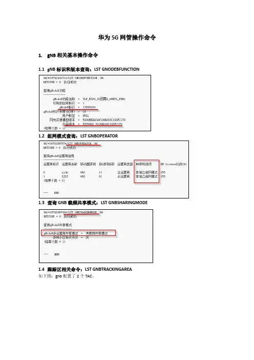
华为5G网管操作命令1.gNB相关基本操作命令1.1gNB标识和版本查询:LST GNODEBFUNCTION1.2组网模式查询:LST GNBOPERATOR1.3查询GNB载频共享模式:LST GNBSHARINGMODE1.4跟踪区相关命令:LST GNBTRACKINGAREA如下图:gnb配置了2个TAC。
如下图,NRDUCELL小区使用TAC=3配置如下图不同运营商配置TAC(当使用默认配置时,NRDUCELL中配置TAC生效)1.5NSA组网S1配置:lst gnbcux1如下图,gNB配置2条S1链路其中两条S1链路配置给不同的运营商1.6NSA组网X2配置:lst gnbcux21.7gNB配置相关算法参数如下:+++ TLF_TLF4_32团南D_GHBTL_PRB2 2020-09-27 16:53:30 O&M #2685406376%%/*1879199173*/LST GNODEBPARAM:;%%RETCODE = 0 执行成功查询gNodeB参数--------------帧偏置(Ts) = 0AOA测量SNR门限(0.01分贝) = -800帧偏置自动修正开关= 关X2-U传输类型= 通过内部网络传输NSA DC资源协同应用场景= 同步NSA DC零毫秒相对帧偏置时钟失步检测开关= 时钟检测开关:关= 时钟失步后处理开关:关时钟失步干扰上报门限(毫瓦分贝) = -95静默检测干扰差门限(分贝) = 6NSA DC优化开关= NSA DC SRB3功能开关:关= NSA DC 快速重传开关:关= 非CA场景NSA DC组合选择开关:关基站深度休眠节能开关= 基带关断节能开关:关GPS时钟源不可用后低频保持时长= 保持工作24小时同步偏差检测开关= 基于GAP的同步偏差检测开关:关前传最大支持光纤长度自适应开关= 关X2传输最大速率(100Mbps) = 1业务接口告警配置开关= 承载X2的底层链路告警屏蔽开关:开= 承载Xn的底层链路告警屏蔽开关:开= 承载NG的底层链路告警屏蔽开关:开CHR功能开关= S-TMSI禁止记录开关:关自动小区绑定基带设备开关= 关稀疏业务差异化处理开关= 稀疏业务差异化处理开关:关(结果个数= 1)--- END2.gNB相关协议参数配置2.1PDCP参数组:LST GNBPDCPPARAMGROUP2.2RLC参数组:LST GNBRLCPARAMGROUP2.3MAC参数组:LST GNBDUMACPARAMGROUP3.DRX功能开启与配置3.1DRX功能开启:LST NRDUCELLUEPWRSAVING3.2DRX相关参数配置3.3DRX周期3.4不同QCI对应不同DRX参数组4.信道管理相关操作4.1信道基本概念下行信道与信号:PDCCH、PDSCH、PBCH、DM-RS、PTRS、上行信道与信号:PUCCH、PRACH、PUSCH其中SSB中包含MIB、SIB和PBCH,因此PBCH配置由SSB配置管理4.2SSB相关配置如下为SSB相关配置,其中SSB扫描周期为20ms,调度周期为80ms;其中频域位置描述方法可配置为GSCN或者NARFCN针对频域位置配置,按照如下要求:4.4PUCCH配置:LST NRDUCELLPDCCH4.6CSI-RS参考信号配置4.7SRS配置5.功率控制相关操作5.1基本概念➢功率控制分为下行功率控制和上行功率控制➢功率控制分为静态功率控制和动态功率控制➢下行功率控制中PBCH、SS、PDCCH和PT-RS支持静态功率控制,PDCCH和PDSCH支持动态功率控制➢上行功率控制包括:PRACH、PUCCH、PUSCH和SRS功率控制5.2小区基准功率设置:LST NRDUCELLTRP注:最大发射功率指的是基带口输出的功率,而小区基准功率还要考虑天线增益和发射填写的数量,具体的计算公式如下:小区基准功率指的是每个RE上额功率,计算公式如下:上面命令中设置的功率实际上设置的是EIRP功率,通过调整EIRP功率,能够设置RRU发射功率,影响整个小区的覆盖范围。
中国移动TD-LTE无线参数设置指导优化手册-华为分册(征求意见稿)目录TABLE OF CONTENTS1 前言1.1 关于本书1.1.1目的本文主要介绍了华为TD-LTE系统版本的各个专题的相关参数,对参数进行介绍和分析,旨在帮助读者理解和使用系统中的参数,提高系统性能。
1.1.2读者对象本手册适用于TD-LTE系统的基本概念有一定认识的华为公司内部工程师。
1.1.3内容组织本手册是基于TD-LTE产品版本的参数介绍,其内容组织如下:第一章:对本手册的目的,读者对象,内容组织进行介绍。
第二章上行资源分配:介绍Sounding RS资源分配和上行调度的参数配置及调整影响。
第三章上行ICIC:介绍上行ICIC相关参数配置及其调整影响。
第四章下行资源分配:介绍PUCCH资源分配、下行CQI调整、下行调度和下行物理控制信道的参数配置及调整影响。
第五章下行ICIC:介绍下行ICIC相关参数的配置及其调整影响。
第六章下行MIMO:介绍下行MIMO(含Beamforming)与CQI模式的参数配置方法及其调整的影响。
第七章移动性管理:介绍切换、重选的参数配置及其调整影响。
第八章LC(过载控制):介绍负载控制算法、随机接入控制算法、系统消息SIB映射、移动性负载平衡算法、准入控制算法的参数配置及其调整影响。
第九章功控算法:介绍影响上行功率控制算法、下行功率控制算法的相关参数及其调整影响。
第十章信道配置&链路控制:介绍影响DRX控制算法、上行定时控制算法、上行无线链路检测算法的相关参数及其调整影响。
第十一章数传算法:介绍影响AQM算法、TCP Agent算法的相关参数及其调整影响。
第十二章传输TRM算法: 介绍影响LMPT接口板下行流控算法、TRM算法的相关参数及其调整影响。
第十三章SON:介绍影响ANR算法、ICIC自组织模式选择算法、MRO算法的相关参数及其调整影响。
1.1.4撰写和评审记录1.1.5参考文献1)< LTE eRAN2 2 性能参数分册>2)<V100R005C00B009 离线MML>3)<LTE TDD eRAN 参数配置规则>4)< -DBS3900 LTE TDD 产品文档-(V100R005C00_01).chm>1.1.6本文的约定和说明本文重点关注和性能相关的参数:(基于M2000平台,以R版本为基础,缺省配置带宽为20MHz,)本文对应的产品版本请参看修订记录,未作特别说明的参数均是该版本的参数。
LTE FDD技术十问十答这篇精要我将会正对LTE的关键技术和网络结构上的演进,以Q&A的形式精简。
至于层1-层3的协议细节大家还是自己看一下指导书中的讲解,记住关键功能即可。
1.什么是LTE?LTE是Long Term Evolution的缩写,可以通俗的把它称之为4G,它初始为3GPP定义的3G技术向后的演进,后续由于CDMA2000向后演进UMB的消亡,LTE成为目前几种主流3G制式WCDMA,CDMA2000,TD—SCDMA向后的演进方向。
LTE分为LTE FDD和LTE TDD两种,系统设备也是不一样的,前者是Frequency Division Duplex CDMA2000和GSM/UMTS的演进,要求1对对称频段,后者是Time Division Duplex,仅要求一段连续频段(请注意TDD 的这个特点)。
中国移动是LTE TDD制式的主推运营商(应该也是唯一的吧)。
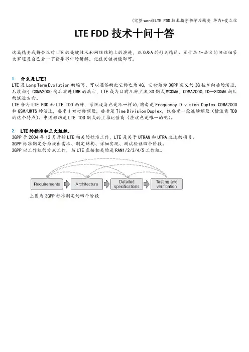
2.LTE的标准和三大组织.3GPP于2004年12月开始LTE相关的标准工作,LTE是关于UTRAN和UTRA改进的项目。
3GPP标准制定分为提出需求、制定结构、详细实现、测试验证四个阶段。
3GPP以工作组的方式工作,与LTE直接相关的是RAN1/2/3/4/5工作组。
上图为3GPP标准制定的四个阶段上图为3GPP标准组织构成目前我们所有提到的LTE实验局等建设都是基于3gpp R8标准,R8是09年3月冻结的。
R9也包含LTE的内容,主要是对于SON功能,ICIC,EMBMS等高级功能的补充和完善,R10通常意义可以认为是LTE-A;LTE中的三个重要组织(这个大家在胶片中经常遇到):1)3GPP——LTE标准的制定者。
2)NGMN—-Next Generation Mobile Network :由众多主流super operator组成,其目的是集合移动运营商的运营经验和市场洞察力,研究和制定下一代移动网络需求(简要说:NGMN目标就是以市场推动标准,引导标准),NGMN组织对三种候选技术(LTE,UMB,WiMAX)进行了评估,最终首选LTE作为下一代移动宽带技术。
华为5G网管操作指导-图文详细介绍2020 5G修改波束(场景覆盖模式)MODNRDUCELLTRPBEAM:NRDUCELLTRPID=0,COVERAGESCENARIO=SCEN ARIO_13;MODNRDUCELLTRPBEAM:NRDUCELLTRPID=1,COVERAGESCENARIO=DEFA ULT;(默认场景)MODNRDUCELLTRPBEAM:NRDUCELLTRPID=1,COVERAGESCENARIO=EXPA ND_SCENARIO_1;(扩展场景)4/5G信令跟踪提取(UU、S1、X2标口,Cell DT日志)一键式日志提取DSP BRD:;(柜号框号槽号查询)批量指令执行(集中任务管理)实时干扰查询:监控->信令跟踪->信令跟踪管理->RSSI 统计监控(查询输入RSSI 自动搜索)->创建->填写跟踪站点名批量小区状态导出:1、配置->报表->网元报表(站点状态)2、配置->报表->RAN报表(基站小区状态)XML文件导出(点击)维护->备份管理->(点击)网元备份->全选网元->(点击)执行(备份)->(点击)刷新->(点击)选择自己备份时间文件->(点击)下载已经选中文件小区偏移量与小区偏置的作用于区别小区偏移量(分贝)该参数表示DU小区与邻区之间的小区偏移量,用于控制测量事件发生的难易程度。
小区偏置(分贝)5G分流参数设置LST GNBPDCPPARAMGROUPSCG ONLY不分流(上下行不分流)MODGNBPDCPPARAMGROUP:PDCPPARAMGROUPID=5,DLDATAPDCPSPLIT MODE=SCG_ONLY,ULDATASPLITPRIMARYPATH=SCG,ULDATASPLITTH RESHOLD=INFINITY;SCG_AND_MCG分流(上下行动态分流)MODGNBPDCPPARAMGROUP:PDCPPARAMGROUPID=5,DLDATAPDCPSPLIT MODE=SCG_AND_MCG,ULDATASPLITPRIMARYPATH=MCG,ULDATASPL ITTHRESHOLD=BIT100;ANR功能开启小区级ANR功能开启LST CELLALGOSWITCH (ANR自动邻区添加功能查询)MODCELLALGOSWITCH:LOCALCELLID=161,ANRFUNCTIONSWITCH=INTRA_ RAT_ANR_SW-1;基站级ANR 功能开启LST ENODEBALGOSWITCH (基站级ANR 开关查询)MOD ENODEBALGOSWITCH:ANRSWITCH=IntraRatEventAnrSwitch-1; (修改)4G\5G 虚用户信令跟踪Trace id460300000000015:37154(CPE ) 460300000000011:8096(CPE ) 460300000000031:49117 (TUE)5G核心网跟踪Trace id5G 设备信息批量导出(RRU和AAU型号导致)测量事件门限,如A1\A2\A3\B1查询NR小区关系LST NRCELLRELATION:;(查询NR小区关系)输出项名称输出结果解释NR小区标识该参数表示小区的标识,在本基站范围内唯一标识一个小区。
2018软考网络工程师《华为基础实验》指导手册目录前言 --------------------------------------------------------------------------------------------------------------- 3实验一 VRP基础操作与Telnet配置 ------------------------------------------------------------------------- 4实验二交换机的基本配置 -------------------------------------------------------------------------------------- 11 实验三配置和实施VLAN ----------------------------------------------------------------------------------------- 16 实验四配置交换机的hybrid接口 --------------------------------------------------------------------------- 27 实验五基于MAC地址划分VLAN ------------------------------------------------------------------------------- 30 实验六配置GVRP协议 ------------------------------------------------------------------------------------------- 33 实验七生成树协议的配置 -------------------------------------------------------------------------------------- 36 实验八配置通过Telnet登录系统 --------------------------------------------------------------------------- 40 实验九 Auto-Config自动配置--------------------------------------------------------------------------------- 44 实验十配置静态路由 --------------------------------------------------------------------------------------------- 50 实验十一配置默认路由------------------------------------------------------------------------------------------ 57 实验十二实施和配置RIPv2 ------------------------------------------------------------------------------------ 65 实验十三 RIP与BFD联动 --------------------------------------------------------------------------------------- 75 实验十四配置多区域的 OSPF协议 -------------------------------------------------------------------------- 79 实验十五 IS-IS协议基本配置 ------------------------------------------------------------------------------- 92 实验十六 BGP协议基本配置 ---------------------------------------------------------------------------------- 96 实验十七 VLAN间的三层通信------------------------------------------------------------------------------- 102 实验十八配置和实施Eth-Trunk---------------------------------------------------------------------------- 111 实验十九配置路由器为DHCP Server --------------------------------------------------------------------- 115 实验二十配置路由器为DHCP中继代理------------------------------------------------------------------- 120 实验二十一配置NAT-------------------------------------------------------------------------------------------- 126 实验二十二配置访问控制列表 ACL------------------------------------------------------------------------ 130 实验二十三基于时间的ACL配置及策略 ----------------------------------------------------------------- 140 实验二十四策略路由配置 ------------------------------------------------------------------------------------ 145 实验二十五 VRRP配置 ------------------------------------------------------------------------------------------ 148 实验二十六 GRE VPN配置 ------------------------------------------------------------------------------------- 151 实验二十七 IPSec VPN配置 ---------------------------------------------------------------------------------- 154 实验二十八 IPv6-overIPv4 GRE隧道配置--------------------------------------------------------------- 161 实验二十九 ISATAP隧道配置 -------------------------------------------------------------------------------- 165 实验三十 NAT-PT配置 ------------------------------------------------------------------------------------------ 167前言1.软考网络工程师在2018年2月1日出版教程《网络工程师教程第5版》,其中网络设备从原来的思科改为华为。
无线网络优化工程师无线网络优化工程师是网络通信领域中的专业人士,主要职责是负责无线网络的规划、设计、优化和维护工作,以确保无线网络的高效运作和最优性能。
随着移动通讯技术的不断进步,越来越多的企业和组织需要招聘无线网络优化工程师来协助他们建立和优化无线网络,满足不断增长的通讯需求。
本文将介绍无线网络优化工程师的职责、技能要求和培训路径,以及行业未来发展趋势等方面的内容。
一、无线网络优化工程师职责1.规划无线网络:从网络结构、硬件设备、软件系统等多个方面进行规划和设计工作,以保证网络安全、顺畅运行。
需要考虑网络传输速度、信号覆盖范围、网络容量、负载均衡、故障恢复等方面问题。
2.优化无线网络:根据实际运行情况,进行网络调优、频率规划、设备升级等工作,保障网络稳定性、运转效率和速度。
3.维护无线网络:及时发现和解决无线网络故障和问题,确保网络系统的正常运行和安全性。
4.提供技术支持:解答用户在无线网络使用过程中的问题,为用户提供技术支持并提出相应改进措施。
5.更新和研究无线网络技术,跟进和应用新技术。
二、无线网络优化工程师技能要求1.具备深入的计算机网络知识,包括网络体系结构、数据传输协议、网络安全和网络管理等方面。
2.熟练掌握无线通讯相关知识,如GSM、CDMA、LTE、WiFi等。
3.熟练掌握相关技术工具和软件,例如网络优化软件、无线网监控设备等。
4.较强的统计分析能力和逻辑思维能力,能够科学有效地分析数据和问题,提出解决方案。
5.良好的沟通能力和团队协作能力。
三、无线网络优化工程师培训路径无线网络优化工程师是一个高级技术职位,需要在相关领域具有深入的知识和经验。
以下是无线网络优化工程师的培训路径:1.本科/硕士学位:通过相关本科或硕士学位获得无线网络相关知识和技能,例如计算机科学、电子工程、通信工程等。
此外,还可以通过网络、课程和研讨会等途径进行补充学习和培训。
2.实习和工作经验:在相关企业或组织中找到实习和工作机会,积累无线网络相关知识和经验,特别是在无线网络优化领域方面积累经验。
一、界面介绍:监控:当前告警、历史告警、信令跟踪维护:MML命令入口、集中任务管理器入口拓扑:主拓扑入口,可直接针对单个站点进行操作、设备面板、告警等性能:指标查询应用启动器:CME入口二、告警查询1、需要查询单个基站故障,在主拓扑查找到基站,右键站点选择查询告警,当前告警或告警日志;2、当前告警中点击告警名称可以获取告警详细信息,根据定位信息和产生原因可以准确看出具体的告警定位和产生原因。
3、查询批量告警需要在主页面-监控-当前告警,能显示本地全部网元的告警,再通过过滤选项,可以过滤选择自己需要的告警,可以通过网元名称、告警名称、告警级别、发生时间等进行筛选。
三、命令执行和批量处理1、在主页面-维护-MML命令可进入MML命令窗口,在窗口内根据需要选择网元,再在命令侧输出相应命令查询对应的结果,命令可以通过中文来搜索;2、输入命令时参数面板会提示需要填写的关键信息,红色字体为必须填写才能执行,黑色字体为根据需要可选择填写;3、在页面输入窗右上角有个重定向,选择后可以保留本次运行的所有结果,关闭窗口再次打开则自动取消重定向;在命令帮助窗口中可以查看本条命令中对应各参数的范围和功能;4、批量加载脚本时在维护-集中任务管理器打开,选择MML脚本-创建;---基本信息需要输入任务名称,不能与现存的相同;---时间设置非定时脚本选择立即执行,定时脚本选择需要执行的时间,自动删除选项可选可不选;---扩展参数内容需要选择对应的脚本和站点,并保存执行结果,点完成后脚本开始执行。
5、批量执行脚本制作,以添加异频邻区为例,将单个小区完整的添加命令在MML命令窗口输出后,复制脚本到excel表中,在表中填入需要的参数,用公式匹配到脚本的对应位置,制作完成后把所有公式所在列复制到TXT文件中,执行时选择该TXT文件;批量脚本分为单站的和多站点的,多站点的需要在命令后方加上:{基站名},所有命令都加上后在执行中的扩展参数页面则无需选择操作的站点。
华为5G网管性能问题分析手册-SA概述目前全省各地市已完成SA商用测试,除了从日常测试与投诉中发现网络存在“点、线”的问题,还需要从性能上发现面上的问题,从而使得NSA网络正常运行,保障5G网络的用户体验感知。
与传统LTE网络一样,需要从“接入性”、“移动性”、“保持性”以及“小区数传能力”几个维度进行性能问题分析定位。
接入性:无线接通率移动性:保持性:无线掉线率一、小区接入性能问题SA组网小区,终端接入5G网络的,主要涉及流程如下:涉及指标:无线接通率计算公式:无线接通率(NR)=(RRC连接建立成功次数/RRC连接建立请求次数)*(Flow 建立成功数/Flow建立请求数)*(NG接口UE相关逻辑信令连接建立成功次数/NG接口UE相关逻辑信令连接建立请求次数)1.1接入问题规定动作1.1.1操作日志&告警故障基站的操作,告警和故障日志可以在U2020和一键式日志内获取,使用FMA 可以直接打开,对于操作日志主要排查是否存在影响接入的操作,主要判断问题时间点与操作时间点是否存在相关性;对于告警及故障主要查看问题时间点,是否存在相关未恢复的告警,如小区不可用、X2接口故障等。
1.1.2参数核查1、通过优化最小接收电平、小区选择参数、小区重选参数、5-4重选参数、邻区核查等手段提升;1.1.3射频通道(发功&上行干扰)排查上行干扰会影响SRS和PUSCH解调性能,严重影响吞吐率性能。
正常情况下底噪在-116dbm左右,干扰跟踪位于M2000 Tracing Monitor->NR->Cell Performance Monitoring.1.2接入问题定位思路NR接入问题涉及问题,可见如下思维导图1.2.1空口未发起RRC_CONN_REQ基站侧没有收到RRCSetupReq,需要在终端侧观察,终端侧是否有发起RRC接入可能原因:➢小区不可用,核查小区状态和故障告警;➢小区状态为BLOCK状态;➢NG-C链路故障或者未配置;➢AAU通道校正失败➢终端不支持NR频段;1.2.2NR随机接入失败当前导致随机接入失败的可能原因有:➢弱覆盖或干扰导致随机接入失败,核查问题小区覆盖和干扰情况;➢超小区半径接入:核查问题小区半径设置是否存在异常。